1
Back to top
Service manual
for the
MCDU 11/1 and MCDU 11/2
LAE microprocessor digital
temperature controllers
UK trade spare parts and servicing
Menu
Service manual
MCDU 11/1 and MCDU 11/2 LAE microprocessor digital temperature controllers
Copyright
Copyright Foster Refrigerator (UK) Limited, November 2000
All rights reserved. No part of this publication may be reproduced, stored in a retrieval system, or
transmitted in any form or by any means, electronic, mechanical, photocopying, recording or
otherwise, without the prior permission of Foster Refrigerator (UK) Limited.
Foster Refrigerator (UK) Limited
Oldmedow Road
KING'S LYNN
PE30 4JU
United Kingdom
Tel: +44 (0) 1553 691122
Fax: +44 (0) 1553 691447
Web: www.fosterrefrigerator.co.uk
November 2000
Page ii
Menu
Service manual
MCDU 11/1 and MCDU 11/2 LAE microprocessor digital temperature controllers
Safety of personnel
Liability
Foster Refrigerator (UK) Limited decline responsibility when an attempt is made to use the
refrigerator for any purpose other than that for which it was designed.
WARNING!
THOSE WHO MAINTAIN THE REFRIGERATOR MUST BE TRAINED
IN STANDARD REPAIR AND MAINTENANCE PRACTICES AND
MUST
HAVE
READ
AND
UNDERSTOOD
THE
SAFETY
INSTRUCTIONS CONTAINED IN THIS MANUAL BEFORE
CARRYING OUT ANY MAINTENANCE.
Operating environment
Temperature
The Refrigerator must be used in a clean, well-lit environment with a stable temperature of
approximately 5°C to 35°C.
Relative humidity
The Refrigerator must be used in an environment with a relative humidity between 20% to 80%
(non-condensing).
Symbols and decals
Personnel must be familiar with all the warning symbols and decals fitted to the Refrigerator.
Failure to recognise a warning and read the associated safety instructions may result in injury or
death.
THIS DECAL IS USED TO INDICATE AN ELECTRICAL HAZARD.
THE REFRIGERATOR MUST BE DISCONNECTED FROM THE
MAINS ELECTRICAL POWER SUPPLY WHEN THIS DECAL IS
ENCOUNTERED DURING INSTALLATION AND MAINTENANCE.
Electrical hazard
WARNING!
THE REFRIGERATOR MUST BE DISCONNECTED FROM THE
MAINS ELECTRICAL POWER SUPPLY WHEN THIS DECAL IS
ENCOUNTERED DURING INSTALLATION, MAINTENANCE OR
SETTING-UP.
November 2000
Page iii
Menu
Service manual
MCDU 11/1 and MCDU 11/2 LAE microprocessor digital temperature controllers
Electro-static discharge (ESD)
CAUTION! Precautions against ESD must be taken to prevent damage to the Refrigerator
control circuits:
(1) Ensure that the operating environment is protected against ESD.
(2) Do not touch electronic circuits or wafers.
(3) Always use a grounded wrist strap while handling electronic circuits.
November 2000
Page iv
Menu
Service manual
MCDU 11/1 and MCDU 11/2 LAE microprocessor digital temperature controllers
1.
General
The LAE WDU is an adjustable microprocessor digital temperature controller complete
with integral function indicator neons and temperature sensing probes.
The following functions are incorporated:
•
Thermostat
•
Defrost control
•
Automatic and manual defrost
•
Fan control (MCDU 11/2 only)
The instrument is supplied to Foster in two versions identified by a label attached to
the top of the instrument casing.
Single probe 3.5m long
•
Colour black attached to probe position 'A'
•
Relays 2 & 3 not connected.
2 probes 3.5m long
November 2000
•
Colour black attached to probe position 'A' (Air Temperature).
•
Colour grey attached to probe position 'B' (Defrost)/Fan Delay
•
3 off relays fitted as standard
Page 1
Menu
Service manual
MCDU 11/1 and MCDU 11/2 LAE microprocessor digital temperature controllers
Dimensions
Range
Accuracy
Resolution
Sensors
Operating
temperature
Sensitivity to
EMI
Elect supply
November 2000
75 x 35.x 70mm
-50 to +150°C
1°K
1°C
PTC 1000; 2 wires
and shield
-10 to +60°C
Relays Power rating
Connections
Power supply
Consumption
Panel Mounting
Front protection
IEC 801
Casing (black)
7amp/240Vac, 210W
screw terminal 4 sq mm
12Vac/dc;10%
2VA
by means of plastic
brackets
IP54
fire retardant
12v 50/60hz
Page 2
Menu
Service manual
MCDU 11/1 and MCDU 11/2 LAE microprocessor digital temperature controllers
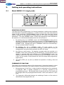
2.
Setting and operating instructions
2.1
Model MCDU 11/1 single probe
FUNCTION OF KEYS
The facia keys allow programming of all control parameters, starting manual defrosts
and checking the evaporator temperature. It allows access to two of the three different
modes of the Instrument: PROGRAMMING mode, in which Set Point and interval
between Defrosts can be displayed or changed and SET-UP mode for configuring the
parameters. The third, NORMAL mode, in which the programmed control sequences
are carried out, is selected automatically when the unit is turned on.
1.
By pressing key [1] in NORMAL mode, the PROGRAMMING of Set point is
activated. By pressing this key when the controller is in PROGRAMMING mode
the programmed value is stored immediately and the controller switches back to
NORMAL mode. Storage and return to NORMAL mode occur automatically if
no key is pressed within 5 seconds.
2.
By pressing key [2] in NORMAL mode you have access to the
PROGRAMMING of the interval between Defrosts. (These values can only be
changed within the preset limits entered in the SET-UP mode).
3.
Key [4] has a dual function. By keeping it pressed while the controller is in
NORMAL mode and by pushing key [2] simultaneously, a manual defrost will be
started. If pressed when the controller is in PROGRAMMING mode, the
displayed value will be decreased; if pressed briefly it will change in one unit at
a time, on the contrary if kept pressed the value will change with progressively
higher speed.
4.
The status LED's (5), (6) and (7) indicate the operation of cooling, fans and
defrost.
THERMOSTAT FUNCTION
The probe is the measuring element of the thermostat; it should be located in a spot
where temperature variations of the cabinet may be correctly and quickly measured.
November 2000
1.
By pressing key [1], Set Point, in other words the temperature to be maintained,
is displayed; "SEt" is digitally displayed for 2 seconds, followed by the
pre-programmed value. By pressing keys [3] and [4], the Set Point value can
be changed within the pre-programmed minimum <vSP> and maximum <^SP>
limits.
2.
The Hysteresis, (differential) between the switching off and on of the cooler is
obtained with the programmed <dt>.
Page 3
Menu
Service manual
MCDU 11/1 and MCDU 11/2 LAE microprocessor digital temperature controllers
3.
Another parameter for cooler control is <PF> - Probe Failure - By setting <ON>
or <OFF>, it is possible to select the relays status in case of a probe failure. If
OFF is programmed, in case of a probe failure the contacts of RL1 will open.
With ON, the cooler (RL1) and the fan will work continuously. The selfdiagnostics of the MCDU 11/1 will display the nature of the defect found by
means of the symbols "PFA".
DEFROST CYCLE
Defrost Cycle comprises all the functions regarding defrost which are carried out by the
MCDU 11/1 from the start of any defrost period to the start of the next one:
•
DEFROST START CONTROL
•
DEFROST EXECUTION
•
DEFROST TERMINATION
•
DRIPPING TIME
1.
By pressing the key [2] when the controller is in NORMAL mode, "dEF" is
displayed for 2 seconds, followed by the Interval between Defrosts previously
programmed. This time represents the hours which should elapse between a
defrost start and the start of the next one. By pressing keys [3] or [4], the
displayed value can be changed within the minimum <vdS> and maximum
<^dS> pre-programmed limits.
2.
The time to start defrost is calculated by the Programmable Timer built into the
MCDU 11/1. The CONTINUOUS TIME mode provides regular defrost starts,
conditioned only by the programmed time and no other variables.
3.
If the evaporator is covered with a thick layer of ice, a Manual Start of defrost is
possible by pressing and holding key [4] and then pressing key [2]
simultaneously. In addition, this action results in timer reset: from that moment
the timer will start calculating the time for the next defrost start.
4.
The defrost execution method should be selected as <ELE>. Because the
MCDU 11/1 has no defrost control relay this will result in the cooling unit being
switched off for the preset timed period.
5.
Defrost will be terminated after the Maximum Time, <ˆdd> has elapsed. At this
point the Dipping Time starts, the duration of which is programmable with the
parameter <dr>. The Dripping Time (the cooler does not work), allows the
water formed from the melting ice to drip from the coil thus preventing its
sudden cooling.
When the Dripping Time has finished, the cooler relay is enabled, but will be
switched on only if ambient temperature has risen over the threshold formed by
SET POINT + Dt.
6.
Another function offered by the MCDU 11/1 is Display Control during defrost
<Cd>. If <dEF> is selected "dEF" will be displayed during defrost in place of
the temperature measured by the probe. To continuously display the
temperature of the probe, choose option <tA>.
7.
During temperature control and defrost the fan works continuously.
MCDU 11/1 PROGRAMMING PARAMETER MODE
1.
November 2000
The MCDU 11/1 can carry out all the functions requested for a specific
application, after the parameters have been programmed in SET-UP mode.
Access to this mode is possible through a sequence of operations preventing
accidental activation.
Page 4
Menu
Service manual
MCDU 11/1 and MCDU 11/2 LAE microprocessor digital temperature controllers
2.
Turn off the unit, press key [1] and [2] and, by keeping them pressed, turn on
the unit. If this operation has been correctly made, 'tHS" will appear on display.
Access to all parameters and to their own pre-programmed values is obtained
by pressing the key [1] repeatedly. The specific value of the parameter can be
changed with keys [3] and [4] within the limits shown in Table 1 . Quick skip
through the menu is achieved with keys [3] and [4] used as shown in the table.
After programming, switch back to the main menu ('tHS", "dEF", "AdJ') and turn
off the unit. When the MCDU 11/1 is switched on, it will enter NORMAL mode
and will work with the new configuration.
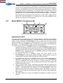
2.2
Model MCDU 11/2 double probe
FUNCTION OF KEYS
The facia keys allow programming of all control parameters, starting manual defrosts
and checking the evaporator temperature. It allows access to two of the three different
modes of the Instrument: PROGRAMMING mode, in which Set Point and interval
between Defrosts can be displayed or changed and SET-UP mode for configuring the
parameters. The third, NORMAL mode, in which the programmed control sequences
are carried out, is selected automatically when the unit is turned on.
November 2000
1.
By pressing key [1] in NORMAL mode, the PROGRAMMING of Set Point is
activated. By pressing this key when the controller is in PROGRAMMING mode
the programmed value is stored immediately and the controller switches back to
NORMAL mode. Storage and return to NORMAL mode occur automatically if
no key is pressed within 5 seconds.
2.
By pressing key [2] in NORMAL mode you have access to the
PROGRAMMING of the interval between Defrosts. (These values can only be
changed within the preset limits entered in the SET-UP mode).
3.
By pressing the key [3] in NORMAL mode, the B probe temperature is
displayed. By pressing this key when the controller is in PROGRAMMING
mode, the displayed value will be increased. If pressed briefly the value will
change in one unit at a time and if kept pressed the value will change with
progressively higher speed.
4.
The key [4] has a dual function. By keeping it pressed while the controller is in
NORMAL mode and by pushing key [2] simultaneously, a manual defrost will be
started. If pressed when the controller is in PROGRAMMING mode, the
displayed value will be decreased; if pressed briefly it will change one unit at a
time, on the contrary if kept pressed the value will change with progressively
higher speed.
5.
The status LED's (5), (6) and (7) indicate the operation of cooling, fans and
defrost.
Page 5
Menu
Service manual
MCDU 11/1 and MCDU 11/2 LAE microprocessor digital temperature controllers
THERMOSTAT FUNCTION
The A probe is the measuring element of the thermostat; it should be located in a spot
where temperature variations of the cabinet may be correctly and quickly measured.
1.
By pressing key [1], Set Point, in other words the temperature to be maintained,
is displayed; "SEt' is digitally displayed for 2 seconds, followed by the
pre-programmed value. By pressing keys [3] and [4], the Set Point value can
be changed within the pre-programmed minimum <vSP> and maximum <ˆSP>
limits.
2.
The Hysteresis (differential) between the switching off and on of the cooler is
obtained with the programmed <dt>.
3.
Another parameter for cooler control is <PF> - Probe Failure - By setting <ON>
or <OFF>, it is possible to select the relays status in case of a probe failure. If
OFF is programmed, in case of a probe failure the contacts of RL1, RL2 and
RL3 will open. With ON, the cooler (RL1) and the fan (RL2) will work
continuously, while defrost (RL3) will be excluded. The self-diagnostics of the
MCDU 11/2 will display the nature of the defect found by means of the symbols
"PFA" or "PFB" (A or B probe failure).
DEFROST CYCLE
Defrost Cycle comprises all the functions regarding defrost which are carried out by the
MCDU 11/2 from the start of any defrost period to the start of the next one:
November 2000
•
DEFROST START CONTROL
•
DEFROST EXECUTION
•
DEFROST TERMINATION
•
AUXILIARY CONTROLS (fan lock out, dripping etc.)
1.
The B probe measures the evaporator temperature and controls all various
defrost control stages such as: defrost termination and fan delay.
2.
By pressing the key [2] when the controller is in NORMAL mode, "dEF" is
displayed for 2 seconds, followed by the Interval between Defrosts previously
programmed. This time represents the hours which should elapse between a
defrost start and the start of the next one. By pressing keys [3] or [4], the
displayed value can be changed within the minimum <vdS> and maximum
<^dS> pre-programmed limits.
3.
The time to start defrost - i.e. the heating up of the evaporator – is calculated by
the Programmable Timer built into the MCDU 11/2. The CONTINUOUS TIME
mode provides regular defrost starts, conditioned only by the programmed time
and no other variables.
4.
If the evaporator is covered with a thick layer of ice, a Manual Start of defrost is
possible by pressing and holding key [4] and then pressing key [2]
simultaneously. In addition, this action results in timer reset: from that moment
the timer will start calculating the time for the next defrost start.
5.
The defrost Execution method should be selected in SET-UP through the
parameter <dH>, since it depends on the system used. Possible solutions
offered by the MCDU 11/2 are: -
Page 6
Menu
Service manual
MCDU 11/1 and MCDU 11/2 LAE microprocessor digital temperature controllers
ELECTRIC HEATING <ELE> when defrost starts, the fan (RL2) and the cooler
(RL1) are turned off and, at the same time, the defrost relay (RL3) for heating
element control is switched on.- HOT GAS <GAS>: when defrost is on, the fan
(RL2) is stopped and the hot gas valve is turned on through the defrost relay
(RL3); the cooler (RL1) continues to pump hot gas to the evaporator. –AIR
<ELE>: this method can be chosen if ambient temperature is above 0°C, in this
case defrost takes place spontaneously by keeping the cooler switched off for a
preset timed period. If a fan is installed, it may be activated by means of the
defrost relay (RL3); in this way defrost duration will be shorter. The RL3 relay
status is shown by the LED (7) with the symbol of the drops of water; when lit,
the contacts No. 1 and 2 are closed.
6.
Defrost will be terminated either when the Temperature of Defrost Termination
<Et> is measured (by B probe) or after the Maximum Time <^dd> has elapsed,
whichever occurs the sooner. At this point all relays drop out and the Dripping
Time starts, the duration of which is programmable with the parameter <dr>.
The Dripping Time (the cooler does not work), allows the water formed from the
melting ice to drip from the coil thus preventing its sudden cooling.
When the Dripping Time has finished, the cooler relay is enabled, but will be
switched on only if ambient temperature has risen over the threshold formed by
SET POINT + Dt.
7.
Another function offered by the MCDU 11/2 is Display Control during defrost
<Cd>. If <dEF> is selected "dEF" will be displayed during defrost in place of
the temperature measured by the A probe. To continuously display the
temperature of the A probe, choose option <tA>.
8.
During temperature control the fan works continuously and is stopped when
defrost starts. Fan Re-start is Delayed from cooler re-start. in order to allow the
evaporator to cool down and reach the programmed ∆T <Fd>, compared to the
temperature of the A probe.
The RL2 relay status is shown by the
corresponding LED (6): when lit, the contacts No 1 and 3 are closed.
MCDU 11/2 PROGRAMMING PARAMETER MODE (SET-UP)
The MCDU 11/2 can carry out all the functions requested for a specific application,
after the parameters have been programmed in SET-UP mode. Access to this mode
is possible through a sequence of operations preventing accidental activation.
1.
Turn off the unit, press key [1] and [2] and, by keeping them pressed, turn on
the unit. If this operation has been correctly made, 'tHS" will appear on display.
Access to all parameters and to their own pre-programmed values is obtained
by pressing the key [1] repeatedly. The specific value of the parameter can be
changed with keys [3] and [4] within the limits shown in Table 1. Quick skip
through the menu is achieved with keys [3] and [4] used as shown in the table.
2.
After programming, switch back to the main menu ('tHS ", "DEF", AdJ') and turn
off the unit. When the MCDU 11/2 is switched on, it will enter NORMAL mode
and will work with the new configuration.
TECHNICAL DATA
1.
The temperature sensors are connected to the unit by means of 2 wires with
shield. The latter is used for increasing the protection of the instrument to
electro-magnetic interference and, at the same time, for protecting the sensor.
The probes are watertight with IP67 protection. To obtain this, connect the
shield to the earth of the cabinet only on the instrument side. The probe cable
should be located away from power lines.
November 2000
Page 7
Menu
Service manual
MCDU 11/1 and MCDU 11/2 LAE microprocessor digital temperature controllers
2.
When installed into the panel the unit has IP 54 front protection.
LAE MCDU 11/1 & MCDU 11.2 FITTING INSTRUCTIONS
To replace an existing Eliwell Microprocessor with an LAE model the following
procedures must be followed.
Replacement of Eliwell EWPC 960 with LAE MCDU 11/1
1.
The 'cut-out' in the cabinet console will accept the LAE controller.
2.
Remove the Eliwell EWPC 960 controller together with the Eliwell temperature
probe.
3.
Fit the LAE MCDU 11/1 and the LAE black temperature probe. It is important
that the routing of the LAE probe is segregated from any current carrying
cables. The earth screen must be connected to the earth terminal of the
control box. It will be necessary to 'extend' the earth screen of the temperature
probe to accomplish this.
4.
Position the end sensor of the temperature probe (probe 'A') as indicated in
Appendix 'A'. Connect the probe as per the label details on the controller.
5.
See the relevant new cabinet wiring diagrams for the correct electrical
connections.
6.
Read the Installation & Operating Instructions for the correct operation and
parameter settings and change if necessary.
7.
If an electrical test is carried out ensure the 12 volt supply to the controller is
disconnected.
8.
After fitting check the operation of the cabinet.
NOTE — Probe 'B' is not fitted on MCDU 11/1 controllers.
Replacement of Eliwell EWPC 971 with MCDU 11/2
November 2000
1.
The 'cut-out' in the cabinet console will accept the LAE controller.
2.
Remove the Eliwell EWPC 971 controller together with the temperature and
defrost termination (if fitted) probes.
3.
Refer to the electrical wiring diagram originally provided with the cabinet and
disconnect the fan delay klixon, if fitted, from the terminal block inside the
control box. Make safe the exposed wires. Wire a 'link' between the terminals
from which the fan delay was removed. The LAE controller does not require a
separate fan delay switch as the function is an integral operation of the
controller.
4.
Fit the LAE MCDU 11/2 controller, the black temperature probe and grey
defrost termination/fan delay probe. It is important that the routing of the
probes is segregated from any current carrying cables. The earth screens
must be connected to the earth terminal of the control box. It will be necessary
to 'extend' the earth screens of the probes to accomplish this.
5.
Position the end sensor of the air (temperature) probe (probe 'A) and the coil
(defrost termination/fan delay) probe (probe 'A') as detailed in appendices 'A'
and 'B' and connect as per details on the controller labels.
6.
See the relevant new cabinet wiring diagram for the correct electrical
connections.
Page 8
Menu
Service manual
MCDU 11/1 and MCDU 11/2 LAE microprocessor digital temperature controllers
7.
If an electrical test is carried out ensure the 12 volt supply to the controller is
disconnected.
8.
After fitting check the operation of the cabinet.
NOTES ON PARAMETER SETTINGS
1.
LAE Temperature Controllers are supplied to Foster by the manufacturer with
all parameters pre set to a 'standard' range.
2.
These standard settings for LAE MCDU 11/1 and 11/2 are shown on the
following pages (setting ref nos 1 and 2).
3.
However some Foster models require a variation to these settings on some of
the parameters (see below).
4.
The following pages list all Foster models fitted with LAE controllers. The
parameter settings required for individual models are shown as a reference
number in the column adjacent to the model number. The settings applicable
to these reference numbers are shown.
NOTE — Reference numbers 1 and 2 are the standard settings, pre set in the
instruments as supplied.
The remaining reference numbers are variations from the 'standard' settings
(see above).
The figures in these columns show those parameters which have to be
changed from standard.
The blank squares indicate that these parameters remain as standard.
NOTE — When replacing an LAE controller with another LAE controller it will be
necessary to change the parameter settings if the model it is fitted to does not have
'standard' settings.
TECHNICAL DATA
November 2000
1.
The temperature sensor is connected to the unit by means of 2 wires with
shield. The latter is used for increasing the protection of the instrument to
electro-magnetic interference and, at the same time, for protecting the sensor.
The probe is watertight with IP67 protection. To obtain this, connect the shield
to the earth of the cabinet only on the instrument side. The probe cable should
be located away from power lines.
2.
When installed into the panel the unit has IP 54 front protection.
Page 9
Menu
Service manual
MCDU 11/1 and MCDU 11/2 LAE microprocessor digital temperature controllers
November 2000
Page 10
Menu
Service manual
MCDU 11/1 and MCDU 11/2 LAE microprocessor digital temperature controllers
November 2000
Page 11
Menu
Service manual
MCDU 11/1 and MCDU 11/2 LAE microprocessor digital temperature controllers
9
10
11 12 13 14 15 116 17 18 19 20 21 22 23 24 25 26 27 28
2
2
2
2
2
2
2
2
2
2
2
2
2
2
2
2
2
2
2
2
-2
-2
-28
-5
-5
+3
3
-20
3
3
2
2
2
1
2
2
2
2
4
2
2
3
3
3
2
-2
-2
-2
8
8
ADUC ADUM
TC TM TM TC TM TC
-1 -3
-3 -1
TC
TM
-3 -1
0
+15 -5
-1 -3
CE ME
-3 -1
ADUC ADUM
TC TM TM TC TM TC
TC TM
+1 -1 -1 +1
+1 -1
-1 +1
OFF OFF OFF
15
5
-10
10 +40 +3
OFF OFF OFF
OFF ON
25
25
10
25
25
15
5
15
15
15
10
15
5
25
25
5
15
CE ME
-1 -1
OFF OFF OFF
25
10
15
0
5
0
4
5
25
3
5
+1
+1
HBS
34
T/2
12 24
ELE
ELE ELE ELE
ELE
1
AD AD AD AD
AD AD
TM TC TM TC
TC TM
-2 0
-0 2
0 -2
November 2000
+1
+1
ELE
8
ELE
ELE
1
-27
-4
-4
-21 -21 +2 +35 -4
Page 12
Menu
Service manual
MCDU 11/1 and MCDU 11/2 LAE microprocessor digital temperature controllers
November 2000
Page 13
Menu
Service manual
MCDU 11/1 and MCDU 11/2 LAE microprocessor digital temperature controllers
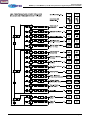
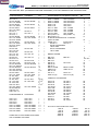
SETTING REF NOS (STANDARD AND NON-STANDARD) FOR LAE TEMPERATURE CONTROLLERS.
MODEL TYPE & NUMBER
GASTRONORM 90 CABINETS
GH 501 U
GH 601 U
GH 1131 U
GH 501 ADUM
GH 601 ADUM
GH 1131 ADUM
GH 501 ADUC
GH 601 ADUC
GH 1131 ADUC
GH 501 UWG
GH 601 UWG
GH 1131 UWG
GH 501 T
GH 601 T
GH 1131 T
GH 1351 T
GH 2101 T
GH 501 ADTM
GH 601 ADTM
GH 1131 ADTM
GH 1351 ADTM
GH 2101 ADTM
GH 501 ADTC
GH 601 ADTC
GH 1131 ADTC
GH 1351 ADTC
GH 2101 ADTC
SGH 601 T
GH 501 UG
GH 601 UG
GH 1131 UG
GH 501 TG
GH 601 TG
GH 1131 TG
GH 1351 TG
GH 2101 TG
GH 601-2-T
GH 1351-4-T
GH 2101-6-T
GH 601 FTT
GH 601-2-TG
GH 1351-4-TG
GH 2101-6-TG
GH 501 ADUCG
GH 601 ADUCG
GH 1131 ADUCG
GH 501 ADTCG
GH 601 ADTCG
GH 1351 ADTCG
GLH 291/291 ADT
GH 501 TWG
GH 601 TWG
GH 1131 TWG
GH 1351 TWG
GL 501 ADU
GL 601 ADU
GL 1131 ADU
GL 501 ADT
GL 601 ADT
GL 1131 ADT
GL 1351 ADT
GL 2101 ADT
SGL 601 ADT
GH 1351 ADUC
GH 1351 ADUM
HD 450 ADU/G
OGH 601 VT
OGH 1351 VT
GASTRONORM 90
COUNTERS
GCH 1/1 E
GCH 1/3 E
GCH 2/1 E
GCH 2/3 E
GCH 1/1 ADME
GCH 1/3 ADME
GCH 2/1 ADME
GCH 2/3 ADME
GCH 1/2 E
GCH 1/4 E
GCH 2/2 E
GCH 2/4 E
GCH 1/2 ADME
GCH 1/4 ADME
GCH 2/2 ADME
GCH 2/4 ADME
REF
NO
1
1
5
9
5
9
6
6
1
1
1
10 C
11 C
9
10
11
9
1
1
1
1
1
1
1
1
1
1
5
9
10
11
1A /7
6
A
D
D
A
A
A
E
E
C
C
A
A
A
A
3
3
3
3
1
1
4
4
4
4
BM2 (COMA - D)
BM3 (COMA - D)
BM4 (COMA - D)
SLIMLINE REFRIGERATOR 1 FREEZER
31
31
(N)LR 125 ADU
(N)HR 125 U
(N)HR 220 U
HR 381 U
HR 731 U
HR 381 ADUM/ADUC
LR 381 ADU
HR 731 ADUM/ADUC
LR 731 ADU
16
1
F
F
F
F
A
A
A
A
7
9
8
BAKERY RANGE
A
A
A
A
A
7
8
2A/12B
2A/12B
8
2A/12B
9
17
26
27
1
1
1
1
3
3
3
3
REF
NO
A
6
WHERE NOT STATED REMOTE SETTINGS
ARE AS NORMAL SETTINGS
November 2000
A
MODEL TYPE & NUMBER
GASTRONORM 90 COUNTERS (CONT'D)
GCH 1/1 ADCE
GCH 1/2 ADCE
GCH 1/3 ADCE
GCH 1/4 ADCE
GCH 2/1 ADCE
GCH 2/2 ADCE
GCH 2/3 ADCE
GCH 2/4 ADCE
GCH 2-2 E
GCH 2-4 E
GCH 2-6 E
GCH 2-8 E
GCL 1/1 ADE
GCL 1/2 ADE
GCL 1/3 ADE
GCL 1/4 ADE
GCL 2/1 ADE
GCL 2/2 ADE
GCL 2/3 ADE
GCL 2/4 ADE
BSF 20 T
DRP 20 T
BSF 34 T
DR 20 VT
DR 24 VE
DR 40 VT
BSCF 16 ADE
HBS 34 T/2
BFF 34 T/2
HW 12 T
HSK 12 T(G)
BSF 40 T
DR 16 VE
BSCF 24 ADE
CBFF 34 T/2
PATF 12 T
PATH 12 T(G)
A
2
G
23 /24H
A
2
18
18
19
4
20
20
21
22
COMPACT COLDROOMS
A
A
KP 410 H
KP 610 H
KP 750 H
KP 1000 H
KP 410 M
KP 610 M
KP 750 M
KP 1000 M
KP 410 L
KP 610 L
KP 750 L
KP 1000 L
KP 530 H
KP 650 H
KP 880 H
KP 1010 H
KP 530 M
KP 650 M
KP 880 M
KP 1010 M
KP 530 L
KP 650 L
KP 880 L
KP 1010 L
28
28
28
28
30
30
30
30
29
29
29
29
A
A
F
E
F
E
F
E
F
E
SOLO WALL/CEILING MOUNT UNITS
50H 32
75H 32
100H 32
150H 32
200H 32
50M 33
75M 33
100M 33
150M 33
200M 33
501 34
75L 34
100L 34
150L 34
200L 34
Page 14
Menu
Service manual
MCDU 11/1 and MCDU 11/2 LAE microprocessor digital temperature controllers
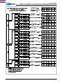
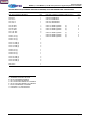
SETTING REF NOS (STANDARD AND NON-STANDARD) FOR LAE TEMPERTURE CONTROLERS.
MODEL TYPE & NUMBER
DOE TBA CONTRACT MODELS
CSH 381 U
CSH 501 T
CSH 601 T
CSH 731 U
CSH 1131 T
CSH 1351 T
REF
NO
1
1
1
1
1
1
CSL 381 ADU
CSL 501 ADT
CSL 601 ADT
CSL 731 ADU
CSL 1131 ADT
CSL 1351 ADT
7
2
2
8
2
2
CSCH 1/1 E (J)
CSCH 1/2 E (J)
CSCH 1/3 E (J)
CSCH 1/4 E (J)
1
1
1
1
CSCL 1/1 ADE (J)
CSCL 1/2 ADE (J)
CSCL 1/3 ADE (J)
CSCL 1/4 ADE (J)
4
4
4
4
CSCH 2/1 E (J)
CSCH 2/2 E (J)
CSCH 2/3 E (J)
CSCH 2/4 E (J)
1
1
1
1
CSCL 2/1 ADE (J)
CSCL 2/2 ADE (J)
CSCL 2/3 ADE (J)
CSCL 2/4 ADE (J)
4
4
4
4
NHR 125 U
NHR 220 U
1
1
MODEL TYPE & NUMBER
DOE TBA CONTRACT MODELS (MEAT/CHILL)
CSH 381 ADUM/ADUC
CSH 501 ADUM/ADTC
CSH 601 ADUM/ADTC
CSH 731 ADUM/ADUC
CSH 1131 ADUM/ADTC
CSH 1351 ADUM/ADTC
REF
NO
5
10
10
CSCH 1/1 ADME (J)/ADCE
CSCH 1/2 ADME (J)/ADCE
CSCH 1/3 ADME (J)/ADCE
CSCH 1/4 ADME (J)/ADCE
(J)
(J)
(J)
(J)
3
3
3
3
CSCH 2/1 ADME (J)/ADCE
CSCH 2/2 ADME (J)/ADCE
CSCH 2/3 ADME (J)/ADCE
CSCH 2/4 ADME (J)/ADCE
(J)
(J)
(J)
(J)
3
3
3
3
NOTES:
A - STANDARD FACTORY SETTING
B - NO.12 FOR REMOTE MODELS
C - NO.13 FOR REMOTE MODELS
D - NO.14 FOR IAN STRANGE LTD CABINETS
E - NO.15 FOR IAN STRANGE LTD CABINETS
F - NO.25 FOR REMOTE COUNTERS
G - FOR MCDU 11/1 CONTROLLER
H - FOR MCDU 11/2 CONTROLLER
November 2000
Page 15