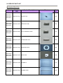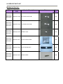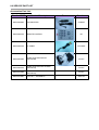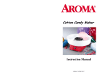
1
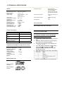
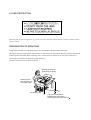
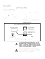
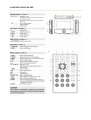
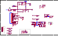
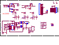
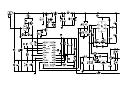
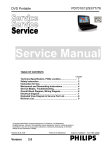
DVD Portable Player
PET722 / PET726
All version
Service Manual
TABLE OF CONTENTS
Chapter
Technical Specification & Service Tips…………..……….. 1
Safety Instructions…………………………………………….. 2
Instruction for Use……………………………………………… 3
Mechanical Instructions………………………………………. 4
Troubleshooting …………………………………………………5
Overall Block Diagram…………………………………………. 6
Electrical Diagram……………………………………………… 7
Service Part List………………………………...………………. 8
Revision List……………………………………………………. 9
©Copyright 2005 Philips Consumer Electronics B.V. Eindhoven, The Netherlands
All rights reserved. No part of this publication may by reproduced, stored in a
retrieval system or transmitted, in any form or by any means, electronics,
mechanical, photocopying, or otherwise without the prior permission of Philips
3141 785 32442
Version 1.2
1.0 TECHNICAL SPECIFICATION
General
Dimensions (W x H x D):
Bear Unit Weight:
Power supply:
Supply voltage
Supply Power
consumption (AC adaptor
100/240VAC)
Operating Temperature
Video System
Frequency response
THD 20-20kHz (%):
Dynamic range 1kHz
Signal/Noise ratio:
Channel Separation 1kHz
Channel Balance 1kHz
Playback disc type:
DVD, Picture-CD,
SVCD, Video CD, MP3CD, CD-R/CD-RW,
WMA-CD, DVD-R, DVDRW, DVD+R, DVD+RW
Video Playback Format:
DVD / VCD / SVCD / CD
/ JPEG
Audio Playback Format:
CD/MP3, MP3-DVD,
DVD
Disc Diameter
12cm
158 x 210 x 39.5 mm
0.79 kg +/- 5%
Input: 100~240V + / - 10%
50/60Hz 0.3A
Output: DC 9V 1A
9W + 10%
0 – 45degC
NTSC / PAL
20-20kHz +/-1dB
</=3%
>/=80dB
>/=80dB
>=80dB
<2dB
Pixel specification
Max. 0 bright-dot & max. 3 dark-dots
Current consumption
Factory Service Mode (FSM)
Playback time
Capacity--- Refer to battery
spec
Battery discharge cut-off
current
Max.battery charge
current(continue charge) of
DCP850 & DCP750
Charging time
≥1600mAH
40mA
400-500
2 +/- 0.5H
Headphone out (headphone output load 2x16 ohm)
Maximum output power:
Frequency response:
SNR (A-wght):
THD (0.2-20kHz):
Left-Right Channel
Separation:
Left-Right Channel
Balance:
Supported disc type
Video Playback
Formats:
Audio Playback
Formats:
1.5mW
+/-3dB
>70dB
3%
>/=50dB
To check the software version and change
region code of your DVD Portable
1. Power ON the DVD player and open the DVD
door
2. Press the “SETUP” button on remote control,
then select the “Preference MENU”
3. Press the remote button in the sequence as
9 -> 6 -> 5 -> 3
4. The LCD display showed the existing region
code. Press
(navigation up) or
(navigation down) repeatedly to select the
number from 0 to 6.
5. Refer below table for your region code setting
</=1dB
Select “0” setting = Region Free (confidential)
1.0 TECHNICAL SPECIFICATION
Procedure on how to upgrade the software of
the DVD Portable
For the best performance of your DVD Portable.
Check www.philips.com/support for latest
software upgrades available.
A) By CD-ROM
1.
2.
3.
4.
5.
Download the “PHILIPS.BIN” file from the Philips
support site
Unzip the file and then burn it into a CD-ROM to
make a disc for upgrade
CD-ROM disc name must be “PHILIPS”
(otherwise it will not be recognized as a disc for
upgrade)
Power on the Portable DVD Player with AC/DC
adaptor
Play CD-ROM for firmware upgrade
Warning: Do not unplug the AC adaptor during
firmware upgrade to prevent flash corrupt of the
set!!
6.
7.
Once upgrade is completed, the player will restart
automatically and observed PHILIPS LOGO on the
screen.
Open the DVD door to remove the disc
1.0 TECHNICAL SPECIFICATION
Service Policy on PCBA of PET722 /
PET726
Type
Main PCBA
TFT PCBA
KEY PCBA
BATTERY PCBA
MLR = module swap
/05
MLR
MLR
MLR
MLR
/12
MLR
MLR
MLR
MLR
/98
MLR
MLR
MLR
MLR
2.0 SAFTETY INSTRUCTIONS
GB
NL
ESD
WARNING
Alle IC’s en vele andere halfgeleiders zijn
gevoelig voor electrostatische ontladingen
(ESD).
Onzorgvuldig behandelen tijdens reparatie kan
de levensduur drastisch doen verminderen.
Zorg ervoor dat u tijdens reparatie via een
polsband met weerstand verbonden bent met
hetzelfde potentiaal als de massa van het
apparaat.
Houd componenten en hulpmiddelen ook op
ditzelfde potentiaal.
All ICs and many other semi-conductors are
susceptible to electrostatic discharges (ESD).
Careless handling during repair can reduce life
drastically.
When repairing, make sure that you are
connected with the same potential as the mass
of the set via a wrist wrap with resistance.
Keep components and tools also at this
potential.
F
WAARSCHUWING
ATTENTION
I
Tous les IC et beaucoup d’autres
semi-conducteurs sont sensibles aux
décharges statiques (ESD).
Leur longévité pourrait être considérablement
écourtée par le fait qu’aucune précaution n’est
prise à leur manipulation.
Lors de réparations, s’assurer de bien être relié
au même potentiel que la masse de l’appareil et
enfiler le bracelet serti d’une résistance de
sécurité.
Veiller à ce que les composants ainsi que les
outils que l’on utilise soient également à ce
potentiel.
D
AVVERTIMENTO
WARNUNG
Alle ICs und viele andere Halbleiter sind
empfindlich gegenüber elektrostatischen
Entladungen (ESD).
Unsorgfältige Behandlung im Reparaturfall kan
die Lebensdauer drastisch reduzieren.
Veranlassen Sie, dass Sie im Reparaturfall über
ein Pulsarmband mit Widerstand verbunden
sind mit dem gleichen Potential wie die Masse
des Gerätes.
Bauteile und Hilfsmittel auch auf dieses gleiche
Potential halten.
Tutti IC e parecchi semi-conduttori sono
sensibili alle scariche statiche (ESD).
La loro longevità potrebbe essere fortemente
ridatta in caso di non osservazione della più
grande cauzione alla loro manipolazione.
Durante le riparazioni occorre quindi essere
collegato allo stesso potenziale che quello della
massa dell’apparecchio tramite un braccialetto
a resistenza.
Assicurarsi che i componenti e anche gli utensili
con quali si lavora siano anche a questo
potenziale.
GB
Safety regulations require that the set be restored to its original
condition and that parts which are identical with those specified,
be used.
“Pour votre sécurité, ces documents
doivent être utilisés par des spécialistes agréés, seuls habilités à réparer
votre appareil en panne”.
NL
Veiligheidsbepalingen vereisen, dat het apparaat bij reparatie in
zijn oorspronkelijke toestand wordt teruggebracht en dat onderdelen,
identiek aan de gespecificeerde, worden toegepast.
CLASS 1
LASER PRODUCT
3122 110 03420
F
Les normes de sécurité exigent que l’appareil soit remis à l’état
d’origine et que soient utiliséés les piéces de rechange identiques
à celles spécifiées.
GB
Warning !
Invisible laser radiation when open.
Avoid direct exposure to beam.
D
Bei jeder Reparatur sind die geltenden Sicherheitsvorschriften zu
beachten. Der Original zustand des Geräts darf nicht verändert werden;
für Reparaturen sind Original-Ersatzteile zu verwenden.
S
Varning !
Osynlig laserstrålning när apparaten är öppnad och spärren
är urkopplad. Betrakta ej strålen.
SF Varoitus !
I
Le norme di sicurezza esigono che l’apparecchio venga rimesso
nelle condizioni originali e che siano utilizzati i pezzi di ricambio
identici a quelli specificati.
Avatussa laitteessa ja suojalukituksen ohitettaessa olet alttiina
näkymättömälle laserisäteilylle. Älä katso säteeseen!
DK Advarse !
"After servicing and before returning set to customer perform a
leakage current measurement test from all exposed metal parts to
earth ground to assure no shock hazard exist. The leakage current
must not exceed 0.5mA."
Usynlig laserstråling ved åbning når sikkerhedsafbrydere er
ude af funktion. Undgå udsaettelse for stråling.
2.1 ESD PROTECTION
Whenthepowersupplyisbeingturnedon,youmaynotremovethislasercautionslabel.Ifitremoves,radiationoflaser
maybereceived.
PREPARATIONOFSERVICING
PickupHeadconsistsofalaserdiodethatisverysusceptibletoexternalstaticelectrocity.
Althoughitoperatesproperlyafterreplacement,ifitwassubjecttoelectrostaticdischargeduringreplacement,
itslifemightbeshortened.Whenreplacing,useaconductivemat,solderingironwithgroundwire,etc.to
protectthelaserdiodeformdamagebystaticelectricity.
Andalso,theLSIandICaresameasabove.
Groundconductive
wriststrapforbody.
Solderingiron
withgroundwire
orceramictype
1M
Conductivemat
Thegroundresistance
betweenthegroundline
andthegroundislessthan10
SAFTY NOTICE
SAFTY PRECAUTIONS
LEAKAGE CURRENT CHECK
Plug the AC line cord directly into a 120V AC outlet (do
not use an isolation transformer for this check). Use an
AC voltmeter, having 5000 per volt or more sensitivity.
Connect a 1500 10W resistor,paralleled by a 0.15uF
150V AC capacitor between a knomn good earth ground
(water pipe, conduit, etc.) and all exposed metal parts of
cabinet (antennas, handle bracket, metal cabinet
screwheads, metal overlays, control shafts, etc.).
Measure the AC voltage across the 1500 resistor.
The test must be conducted with the AC switch on and
then repeated with the AC switch off. The AC voltage
indicated by the meter may not exceed 0.3V.A reading
exceeding 0.3V indicates that a dangerous potential
exists, the fault must be located and corrected.
Repeat the above test with the DVD VIDEO PLAYER
power plug reversed.
NEVER RETURN A DVD VIDEO PLAYER TO THE
CUSTOMER WITHOUT TAKING NECESSARY
CORRECTIVE ACTION.
READING SHOULD NOT EXCEED 0.3V
AC VOLTMETER
DVD VIDEO PLAYER
(5000 per volt
or more sensitivity)
1500
10W
AC OUTLET
Good earth ground
such as a water pipe,
conduit, etc.
0.15uF 150V AC
Test all exposed metal.
Voltmeter Hook-up for Leakage Current Check
The lightning flash with arrowhead symbol, within an
equilateral triangle, is intended to alert the user to the
presence of uninsulated "dangerous voltage" within the
product's enclosure that may be of sufficient magnitude to
constitute a risk of electric shock to persons.
The exclamation point within an equilateral triangle is
intended to alert the user to the presence of important
operating and maintenance (servicing) instructions in the
literature accompanying the appliance.
2.2 SAFETY INSTRUCTIONS
Battery Handling Guideline
Since the battery is packed in soft package, to ensure its better performance, it’s very important to carefully handle
the battery
2.2.1 Soft Aluminium foil
The soft aluminum packing foil is very easily damaged by sharp edge parts such as Ni-tabs, pins and needles.
• Don’t strike battery with any sharp edge parts
• Trim your nail or wear glove before taking battery
• Clean worktable to make sure no any sharp particle
2.2.2 Sealed edge
Sealing edge is very flimsy
• Don’t bend or fold sealing edge
2.2.3 Folding edge
The folding edge is form in battery process and passed all hermetic test.
• Don’t open or deform folding edge
2.2.4 Tabs
The battery tabs are not so stubborn especially for aluminum tab.
• Don’t bend tab
2.2.5 Mechanical shock
• Don’t Fall, hit, bend battery body
2.2.6 Short
Short terminals of battery is strictly prohibited, it may damage battery.
3.0 INSTRUCTION FOR USE
4.0 MECHANICAL INSTRUCTION
Disassembly Procedure
1. Remove 5pcs of screws on the side of
bottom cabinet (include the one behind
plastic stand).
2. Slip the TFT section, then you can open
the bottom cabinet. Be careful of the FFC
which connect with main board and TFT
board.
2. Open the bottom cabinet, up-plug all the
wire connecter from main board (include the
FFC connect with TFT board and main
board),
The wire connecter are for:
DVD loader,
Battery board.
Remove all the screws on the main board
(3pcs), and then take the main board from
bottom cabinet.
4.0 MECHANICAL INSTRUCTION
3. Up-plug the FFC from DVD driver, then
you can take out the DVD Driver.
4. Remove the flex FFC on the bottom side
behind the black flannel.
5. Remove 4pcs of screws on the battery
board.
Then take out the battery together with the
battery board.
Note: the battery was fixed by two side tape!
Remove 6pcs of screws on the DVD top
cabinet, you can separate the DVD top
cabinet and TFT back cabinet.
4.0 MECHANICAL INSTRUCTION
6. Remove 8pcs of screws on the TFT back
cabinet. Then you can open the display
frame, carefully! ( There is a catch as shown
in the pictures)
7. To remove the hinge, remove the screws
on the hinge.
8. To remove the TFT, de-soldering the wire
connected between panel and TFT board first;
After this, up-plug the FFC from TFT board
which behind the black flannel;
Then you can separate the panel.
Be aware that the panel is fixed by 4pcs two side
tape
4.0 MECHANICAL INSTRUCTION
9. up-plug the speaker line from TFT board,
and don't forget de-soldering the black
ground wire behind black flannel.
At last you can take out the driver board from
cabinet using eradicator.
10. Don’t forget to up-plug the FFC which
connect with TFT board and main board
5.0 TROUBLESHOOTING
SYMPTOM: BATTERY NO POWER
BATTERY CAN'T
Power ON
Start
Check Battery capacity?
no
Check charging
function OK?
Check adaptor
power-ON OK?
Yes
yes
SET OK?
Yes
No
Check the Power-ON
button and cable OK?
NO
Replace Button or
Cable
No
Yes
Replace Main Board
No Defect, return
set to Customer
5.0 TROUBLESHOOTING
SYMPTOM: NO IMAGE / NO SOUND
SYMPTOM: NO IMAGE OUTPUT ( THE PANEL SHOW BLUE PICTURE)
Start
Check DVD Drive work?
no
Replace DVD Drive
no
Exchange AV cable
yes
NOTE: AV Cable TYPE from outside to
Inside L-Audio, R-Audio, Video, Ground
Check the external AV
Cable TYPEnote and
connection is OK?
yes
Replace Main Board
SYMPTOM: NO SOUND COMES FROM SPEAKER
Start
Check the Connection OK?
no
Reinsertion
no
Change the speaker
yes
Check speaker OK?
yes
Replace Main Board
5.0 TROUBLESHOOTING
SYMPTOM: THE DVD DRIVE DOES NOT WORK
SYMPTOM: THE DVD DRIVE DOESN'T WORK
Start
Check DVD-Loader
connection OK?
NO
Cable Reinsertion
NO
Replace DVDLoader
Yes
Check the DVD-Loader
OK?
Yes
Replace main board
5.0 TROUBLESHOOTING
SYMPTOM: ADAPTOR CANNOT POWER ON
Adaptor can not Power ON
Start
Check Adaptor OK?
NO
Change adaptor
SET OK?
Yes
Yes
No
Check the Power-ON
button and cable OK?
YES
Return set to
Customer
Replace Main Board
NO
Replace Button or
Cable
OK
5.0 TROUBLESHOOTING
SYMPTOM: REMOTE CONTROL CANNOT WORK
SYMPTOM: THE REMOTE CONTROL CAN NOT
WORK
Start
Check CABLE form
bottom board to top board
connection OK?
NO
Cable Reinsertion
NO
Replace IR receiver
Yes
Check TOP-board OK?
NO
Replace top board
OK
Yes
OK
Replace main board
OK
Return to custormer
5.0 TROUBLESHOOTING
SYMPTOM: NO SOUND FROM HEADPHONE
5.0 TROUBLESHOOTING
SYMPTOM: LED DISPLAY FAILURE
SYMPTOM: LED Display Fail
Start
Check CABLE form Main board to top board
connection OK?
NO
Cable Reinsertion
Yes
Check TOP-board OK?
NO
Replace LED
NO
Replace top board
OK
Yes
OK
Replace main board
OK
Return to custormer
5.0 TROUBLESHOOTING
SYMPTOM: KEY & BOTTON FAILURE
SYMPTOM: Key & Botton Fail
Start
Check CABLE form board to
board connection OK?
NO
Cable Reinsertion
Yes
Check KEY board OK?
NO
OK
Yes
Replace main board
Replace KEY board
OK
Return to custormer
6.0 BLOCK DIAGRAM
7.0 ELECTRICAL DIAGRAM
The diagrams listed on the following pages:
Part 1 – Schematic diagram of MAIN BOARD (1 page)
Part 2 – Schematic diagram of TFT DRIVER BOARD (1 page)
Part 3 – Schematic diagram of BATTERY BOARD (1 page)
Part 4 – PCBA layout diagram of MAIN BOARD (2 page – top and bottom side)
Part 5 – PCBA layout diagram of TFT DRIVER BOARD (2 page – top and bottom side)
Part 6 – PCBA layout diagram of BATTERY BOARD (2 page – top and bottom side)
5
4
10K
15V
2
ON/OFF
2
5
1
6
Q3
3904
Q4
4
RED
D2
3904
R5
B-CHARG
R8
560R
+
EC3
NC
C3
0.1uF
CHARGE ON INDICATION
Low Voltage Det
R22
R23
Q8
3904
4.7K
Q9
2
3904
R24
3K6 1%
L-851
2
D6
1
C17
0.1uF
D7
Q5 2307
2
3
2
R13
SK34
100K
R14
4001
1000pF 0.1uF
100K
R17
1
3
C18
30K 1%
DC JACK(+9V~+12V)
DC_IN
DC_IN
C15
0.1uF
1
4
1
1
3
15V
2
C16
D8
L5
2A_FUSE
2
J2
2
!
10K
33K 1%
SK34
F1
R20
R21
10K
10K
D3
1
D
V33
DC_IN
1
C7
0.1u
POWER OFF
switchpower
4
3
R3
B-CHARG
DISCHARG
3
2
D1
0
910 1%
POWER ON
CHARGE
1
R2
R4
J1
CES2307
R1
22k 1%
1
BATTERY
Q2
1
battery charge
+9VDCIN
D
2
3
+
Q6
ON/OFF
2N3904
EC7
100uF/25V
Q7
3904
R19
1.2K 1%
D14
SP_R
3
GND
4
GND
5
9V
6
9V
7
5V
8
GND
9
SP_L
4
C
SP_R
4
+
L10
EC12
22uF/25V
0.1uF
L11
+
EC15
10
K3
11
K2
TRIN
12
VCOM_DC
13
K4
14
K4
15
89KP_VCOM
GND
16
STVL
17
CKV
18
K1
19
GND
20
TFT_R
21
FB600R
STVL
CKV
2
0.1uF
3
C26
0.1uF
2
U2
IN
OUT
V18
1
+ EC18
GND
V18
C27
100uF/10V
AAC1117-1.8
2SB1132
0.1uF
10K/VR
DV33
2
C114
AR63
AR59
NC
NC
9K1
L13
RFV33
FB600R
+ EC16
RFV33
C25
0.1uF
100uF/10V
TFT_B
22
TFT_B
TFT_G
23
TFT_G
GND
24
R25 0R
25
CPH1
30
C51
33pF
C131
C130
C129
C28
NC
NC
NC
NC
C87
3300P
R151 27K
3300P
R120 33K
EN2
FB2
4
SW2
6
COMP1
14
SS1
COMP2
5
SS2
12
SCP
DC_IN
+
+
Q1
3
2
2307
C21
L6
D16
3
FB2
FB1
V33
R26
2K/NC
GREEN
POWER ON
INDICATION
NC
D9
B
C30
NC
22uH
+
1uF
SK34
1uF
C101 100P
R152 68K
C42 NC
C29
1000pF
EN1
2
C43
BL_EN 2
0.01uF
1
10
+
R149 120K R150 30K
C19
13
EC11 100uF/16V
BLEN
SW1
GND
EC19 100uF/25V
FB2K2
VG
9
22uH
R154 13K
ELEN
8
L9
2
R153 30K
2
FB1
2307
C126 1uF
OEH
VIN
3
FB1
EC26 100uF/16v
29
+
11
NC
OEH
DC_IN
U11 AT1793SOP-14
7
SK34
2
22uH
D17
IR
L1
C125
28
DC_IN
C124 1uF
IR
Q10
2
EC14 100uF/25V
2
2
C53 1uF
OEV
STHL
C52 0.1uF
26
27
EC10
OEV
STHL
C13
FB2
POWER
STVL
CKV
OEV
OEH
STHL
CPH1
89KP_VCOM
4
4
2,3
2
2
2,4
2
URST#
2
L15 1.8uH
89KP_R
R27
Low Voltage Det 2
150
STVL
CKV
OEV
OEH
STHL
CPH1
89KP_VCOM
2
2
2
2
2
2
2
89KP_R
89KP_G
89KP_B
2
2
2
BL_EN
2
TFT_R
C31
C32
100pF
100pF
DV33
L16 1.8uH
89KP_G
R28
150
TFT_G
C33
C34
100pF
100pF
A
2
URST#
Low Voltage Det
VCC3
DC_IN
DV33
RFV33
V18
VCC
AVCC
R7
15K
PANEL I/F
L17 1.8uH
89KP_B
R30
150
5
R11
3.3K
Q17
R6
TFT_B
C36
C37
100pF
100pF
R10 3.3K
4.7K
4
Q11
3904
D10
NC
R29
22K
EC20
C35
URST#
1
VCC3
DC_IN
DV33
RFV33
V18
VCC
AVCC
BL_EN
C20
TFT_R
L14
A
DV33
0.1uF
AVCC
10uF/16V
NC
DV33
C23
100uF/10V
AVCC
+ EC17
C127 0.1uF
89KP_R
89KP_G
89KP_B
FB600R
AS1
AR62
150/nc
2
L8
100uF/10V
2
C128
K1
10uH
+ EC9
2
FB600R
+ EC13
L7
VCC
C24
0.1uF
100uF/10V/NC
TRIN
89KP_VCOM
30PIN/1.25MM/
V33
VCC
K2
CPH1A
DC_IN
L12
K3
B
FB600R
C22
1
AGND
2
1
1
22uF/25V
C
SP_L
3904
+
22UF/25V
1uF
Closed to
IC's pin
RESET Circuit
3
2
1
5
4
2
3
1
5V
5V
AR38
10K
AR64
NC
1uF
2
AQ8
AC22
SS214U
1
+15V
VGH
AR35
AE2
1K
5
5
4
4
10uF/16V(A)
1
1
2
2
3
3
AC15
AR30
AC14/NC
0.1uF
10K
0.1uF
10uF/16V/1206
AR29
AR61
+5V
47K
AR33
AR34
89KP_VCOM
51K
2
0
3
AU2A
1
89VOM_DC
AR60
AR32
1
10R
-6V_VOP
AC23
K4
14
0.1uF
89KP_VCOM
0
2
+
C
AC17
AR65
AL3
+5V
+
0.1uF
2.2uF/0805
AC25
18
CKV
K1
19
K1
GND
21
TFT_RA
TFT_B
22
TFT_BA
TFT_G
23
TFT_GA
GND
24
25
CPH1A
OEV
26
OEV
STHL
27
STHL
CPH1A
VGL
VGH
CKV
UND
OEV
VCOM
01
02
03
04
05
06
07
08
09
10
11
12
MOD 13
14
15
16
CPH3
17
CPH2
18
19
20
21
22
23
24
25
26
STVR
STVL
LNR
IR1
OEH
STHL
STHR
CPH1
ROUT
GOUT
BOUT
+5V
AC26
0.1uF
IR
OEH
29
OEH
ELEN
30
BL_EN
AJ1
GND
VCC
VGL
VGH
STVR
STVL
CKV
U/D
OEV
VCOM
VCOM
LR
MOD
OEH
STHL
STHR
CPH3
CPH2
CPH1
VCC
GND
VR
VG
VB
AVDD
AVSS
1
2
3
4
5
6
7
8
9
10
11
12
13
14
15
16
17
18
19
20
21
22
23
24
25
26
GND
VCC
VGL
VGH
STVR
STVL
CLK
U/D
GOE
VCOM
VCOM
L/R
MOD
SOE
STHL
STHR
CPH3
CPH2
CPH1
VCC
GND
VR
VG
VB
AVDD
AVSS
26PSMD0.5MM
Bottom Socket
IR
28
0.1uF
10uF/10V/0805
C
30PIN/1.25MM/
AMP_VDD
V_BIAS
AR57
AR54
20K
470
AC30 1uF/0805
AMP_VDD
AR40
1
AR53
470
ROUT
AQ5
2
V_BIAS
AR52
20k
1M
AC26 1uF/0805
Vdc
3
TFT_R
+
AC39
7" PANEL
D1
STVL
TFT_R
0
3
10uF/16V(A)
89KP_VCOM
20
AC29
10uF/10V/0805
30K
10uF/25V
AMP_VDD
V_BIAS
AL2
AC40
AC35
16
2
LT070W02
+ AE1
K4
15
17
1
4
K2
VCOM_DC
CKV
-12V
VGL
K3
TRIN
GND
AC24
0.1uF
10
STVL
LG&PHILIPS
+5V
VCOM_DC
0.1uF
+5V
Panel Gate Driver Power
GND
9
11
AC21
10uF/16V/1206
NC
10uF/10V/0805
AR31 470
8
13
AQ10 SS214U
1
3
7
5V
12
AC34
+
2
10uF/16V(A)/10UF10V
-6V_VOP
6
9V
D
5V
K2
VCOM DAC OP POWER
+
AE6
SP_R
+9V
TRIN
10R
SS214U
1
AC36
AC18 1uF
9V
VCOM
K3
0.1uF
3
5
CSC3414A DMP8 HWCAT
5V
AC20 1uF/0805 AQ9
2
4
GND
10uF10V
AC13/NC
2K
3
GND
89P VCOM DAC OUTPUT
+ AC38
AU3
SS6608
2
SP_R
10K
SP_L
1
AGND
4
1
0.1uF
SP_L
-6V_VOP
AC37
2
SSD03
2
100K
8
1
0.1uF
2
AC12
0.1uF
AD1
1
+
AR28
AC11
22uH
-
AC16
AL4
AR39
SMD-1
3
+5V
D
UND
LNR
10pF
1
2
3
AC19
AC31 1uF/0805
TFT_G
2N3904
AR55
AR56
AR41
7K5
75/1%
1M
AR49
AR42
AC27 1uF/0805
AR48
1M
Vdc
3
1
TFT_B
7K5
AC32
AC28 1uF/0805
1uF/0805
AR44
1M
Vdc BOUT
3
AQ7
2
2N3904
1
AR50
75/1%
AR51
470
20k
GOUT
AQ6
2
V_BIAS
AMP_VDD
2N3904
AR43
AR47
AR46
1M
7K5
75/1%
AR45
1M
BJT Amplifier for T-CON I/F
100uH
2
AU4
AE5
0.1uF
10uF/16V(A)
AR26
AD3
22K
5.6V
2
2
16
V-D
15
3
FB1
A-D
14
AU5
10R
AR1
FB2
AR10
V-D
12
11
7
TFB
RT
10
8
ATC
CT
9
SS7707
8
2
3
7
6
AD2
4
5
AC8
5.6V
AR8
1
AC1
0.1uF
100R
AQ2 3906
2.2K
2
3
820
AR13
1
3.9K 1%
TP4
LED
100R
LED
KS10
UP
KS5
RIGHT
GND
AR14
AR11
1K
10K
DOWN
TP5
AQ3
AR17
1
100R
2
BLEN
A
1
1
AR16
2N3904
10K
2
0.1uF
K4
LED
2
AC7
680R
AR77
2
2
1
1
AR19
100R 100R
AR12
4K7
AQ4
2
100R
100K
2
2N3904
2
3
AR71 AR73 AR75
KS6
2
AR6
3
10K
2
+5V
LED
LEFT
A
AR18
1
TP3
KS9
AR15
470R
0.1uF
AR20
K3
+5V
1K
2
AR25
AR24
2200P
KS2
1
AR7
2
1
10R
2
22K
AC6
TP2
2
4.7K
13
GND
STM4532
1
1
REF2
6
1
2
4k7
5
B-D
K2
1
1
2
100K NTC 1%
NC
000
STOP
2
2
4
AR21
1
1
4700P
2
22K
B
KS1
HV3
TP1
KS7
1
AC3
2
100R
AR22
1
2
1
2
AR27
1
7V5
VCC
REF1
5
K1
2.2uF/50V
1
AR4
3
3906
AD4
REF
6
3
4
!
SS214U
AC33
1
2
2
1
1
2
AQ11
1
AU1
2.2uF
2
30K
330K
AQ1
AC4
0.1uF
HV+
7
2
AC2
AR5
33K
5
AR23
1
AR2
AR9
4
0.1uF
2
1
1
AR3
470
1
1
1
AC9
7
6
TRANSFORMER DC-AC CI-8.5 (SKT)
1
AC5
2
3
AT1
1
2
2
10/0805
2
8
1
AR58
1
2
+5V
1
B
STM4532
1
2
0.1uF
100uF/25V/DIP
1
AE4
2
AC10
1
1
2
AL1
1
+9V
5
4
3
2
1
8.0 SERVICE PART LIST
Electrical Part List:
CTN
Service 12NC
Service Description
Photo
Pos.
No.
PET722/79
PET722/98
PET726/37
996510011223
MAIN PCBA
100
PET722/79
PET722/98
PET726/37
996510011210
TFT DRIVER PCBA
110
PET722/79
PET722/98
PET726/37
996510011211
BATTERY PCBA + BATTERY PACK
120
PET722/79
PET722/98
PET726/37
996510011212
KEY PCBA
130
PET722/79
PET722/98
PET726/37
996510002384
24PIN 130MM FFC
141
PET722/79
PET722/98
PET726/37
996510019998
30PIN 140MM FFC
142
8.0 SERVICE PART LIST
Mechanical Part List:
CTN
Service
12NC
Service Description
Photo
Pos.
No.
PET722/79
PET722/98
996510009852
7” LCD PANEL
PET726/37
996510002360
7” LCD PANEL LG E2
PET722/79
PET722/98
PET726/37
996510007686
DVD LOADER
210
PET722/79
PET722/98
PET726/37
996510011214
MONITOR TOP ASB + SPEAKERS
300
PET722/79
PET722/98
PET726/37
996510013820
MONITOR BOTTOM ASB
310
PET722/79
PET722/98
PET726/37
996510011216
DVD TOP ASB
320
PET722/79
PET722/98
PET726/37
996510011217
DVD BOTTOM ASB
330
PET722/79
PET722/98
PET726/37
996510011218
NAVIGATION BUTTON
340
200
8.0 SERVICE PART LIST
Mechanical Part List:
No.
Service
12NC
Service Description
Photo
Pos.
No.
PET722/79
PET722/98
PET726/37
996510011219
OK BUTTON
350
PET722/79
PET722/98
PET726/37
996510011220
MENU BUTTON
360
PET722/79
PET722/98
PET726/37
996510015422
AV OUT/DVD BUTTON
370
PET722/79
PET722/98
PET726/37
996510011222
POWER BUTTON
380
PET722/79
PET722/98
PET726/37
996510011224
MONITOR LENS
390
PET722/79
PET722/98
PET726/37
996510011225
DVD LENS
400
PET722/79
PET722/98
PET726/37
996510011226
STAND PC
410
PET722/79
PET722/98
PET726/37
996510011227
STAND STEEL
420
8.0 SERVICE PART LIST
Mechanical Part List:
CTN
Service
12NC
Service Description
Photo
Pos.
No.
PET722/79
PET722/98
PET726/37
996510011228
R STAND LOCK POM
430
PET722/79
PET722/98
PET726/37
996510011229
L STAND LOCK POM
440
PET722/79
PET722/98
PET726/37
996510011230
WHEEL POM
450
PET722/79
PET722/98
PET726/37
996510011231
PLATE SLIDE STEEL
460
PET722/79
PET722/98
PET726/37
996510011232
PLATE MICRO-NET
470
PET722/79
PET722/98
PET726/37
996510011233
HINGE STEEL
480
8.0 SERVICE PART LIST
Accessories Part List:
Service 12NC
Service Description
Photo
Pos. No.
996510006564
CAR ADAPTER
CARAPT
996510004972
REMOTE CONTROL
996510004975
AV CABLE
996510002353
AC/DC ADAPTER FOR EU
(PET722/98)
ACAPT
996510005473
AC/DC ADAPTER FOR AUS/NZ
(PET722/79)
ACAPT
996510010992
AC/DC ADAPTER FOR US
(PET726/37)
ACAPT
996510019997
PAC132 2nd SCREEN E2
PAC132
RC
AVCABLE
9.0 REVISION LIST
Version 1.0 (3141 785 32440)
• Initial release PET722/98
Version 1.1 (3141 785 32441)
• Add the part list for PET722/79
Version 1.2 (3141 785 32442)
• Add the part list for PET726/37