1
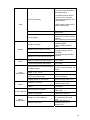
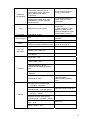
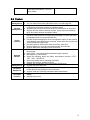
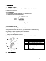
F4X5 Indoor Series Fixed Network Camera User’s Manual Table of Contents 1 2 3 General Introduction ................................................................................................................... 6 1.1 Feature ........................................................................................................................... 6 1.2 System Requirement .................................................................................................... 7 Specification................................................................................................................................. 8 2.1 Technical Specification ................................................................................................ 8 2.2 Feature ......................................................................................................................... 12 Installation .................................................................................................................................. 13 3.1 Install CS Camera ....................................................................................................... 13 3.1.1 Suitable lens ......................................................................................................... 13 3.1.2 About Auto Iris Lens ............................................................................................ 13 3.2 Lens Installation .......................................................................................................... 13 3.3 Remove Lens............................................................................................................... 14 3.4 Real Panel .................................................................................................................... 14 3.4.1 I/O Port (RS485) Pin Distribution ...................................................................... 15 3.4.2 I/O socket .............................................................................................................. 15 3.4.3 Alarm Input and Output ....................................................................................... 16 4 3.5 Profile ............................................................................................................................ 16 3.6 SD Card Installation .................................................................................................... 17 3.7 PC or Network Connection ........................................................................................ 17 Operation Flow Diagram .......................................................................................................... 19 4.1 Operation after Your First Time Installation ............................................................ 19 4.2 5 IE Security Setup ........................................................................................................ 21 Client Operation ........................................................................................................................ 24 5.1 Network Connection ................................................................................................... 24 5.2 Login and Logout ........................................................................................................ 24 5.3 Go to Real-time Monitor Mode .................................................................................. 25 5.4 Video (Right-click Mouse Menu)............................................................................... 25 5.4.1 5.4.2 5.4.3 5.4.4 5.4.5 5.4.6 5.4.7 5.4.8 5.4.9 Real-time Monitor ................................................................................................. 26 Start Dialog ........................................................................................................... 26 Playback Control Bar ........................................................................................... 26 Volume Adjustment.............................................................................................. 26 Alarm Settings ...................................................................................................... 26 Net Data Flux ........................................................................................................ 27 Full-screen ............................................................................................................ 27 Video Zoom ........................................................................................................... 27 PTZ Control ........................................................................................................... 28 5.5 Search........................................................................................................................... 30 5.6 Configure ...................................................................................................................... 31 5.6.1 5.6.2 5.6.3 5.6.4 5.6.5 5.6.6 5.6.7 5.7 Load and Save Configuration ............................................................................ 31 General .................................................................................................................. 32 Record ................................................................................................................... 33 Image ..................................................................................................................... 34 Alarm ...................................................................................................................... 35 Video Detection .................................................................................................... 37 Network.................................................................................................................. 39 Assistant ....................................................................................................................... 41 5.7.1 5.7.2 5.7.3 5.7.4 5.7.5 Change Language ............................................................................................... 42 User Manage ........................................................................................................ 42 Record Control ..................................................................................................... 45 Log Information .................................................................................................... 45 Date Time .............................................................................................................. 45 5.7.6 System Information .............................................................................................. 46 5.7.7 Alarm Prompt ........................................................................................................ 46 5.7.8 Camera Title ......................................................................................................... 47 5.7.9 Upgrade BIOS ...................................................................................................... 47 5.7.10 Mail Setting .................................................................................................... 47 5.7.11 Reboot ............................................................................................................ 49 5.7.12 Record Directory .......................................................................................... 49 5.7.13 Auto Maintenance ......................................................................................... 50 5.7.14 About ............................................................................................................... 50 5.8 6 Un-install web control ................................................................................................. 50 Pro Enterprise Surveillance System ...................................................................................... 51 6.1 Log in ............................................................................................................................ 51 6.2 Enable Monitor ............................................................................................................ 52 6.3 Add New Device .......................................................................................................... 53 7 Auto Search IP Tool ................................................................................................................. 55 8 Appendix: Factory Default Setup ............................................................................................ 57 8.1 General ......................................................................................................................... 57 8.2 Schedule....................................................................................................................... 57 8.3 Video ............................................................................................................................. 57 8.4 Alarm ............................................................................................................................. 57 8.5 Motion Detection ......................................................................................................... 58 8.6 Network......................................................................................................................... 58 8.7 Video setup .................................................................................................................. 58 8.8 Assistant setup ............................................................................................................ 58 Welcome Thank you for purchasing our network camera! This user’s manual is designed to be a reference tool for the installation and operation of your system. Here you can find information about this series Network Camera features and functions. Before installation and operation please read the following safeguards and warnings carefully! Important safeguards and warnings 1.Electrical Safety All installation and operation here should conform to your local electrical safety codes. We assume no liability or responsibility for all the fires or electrical shock caused by improper handling or installation. 2.Transportation Security No heavy stress, violent vibration or water splash are allowed during transportation, storage and installation. 3.Installation Keep upwards. Handle with care. Do not apply power to the Network Camera before completing installation. 4.Qualified Engineers Needed All the examination and repair work should be done by the qualified service engineers. We are not liable for any problems caused by unauthorized modifications or attempted repair. 5.Environment This series Network Camera should be installed in a cool, dry place away from direct sunlight, inflammable, explosive substances and etc. 6. About Camera Camera should be installed away from direct sunlight or other strong artificial lights to avoid blooming and smear. Only use mild detergent or dry cloth to clean the camera. 7. About Accessories Be sure to use all the accessories recommended by manufacturer. 1 General Introduction This series Network Camera adopts traditional camera feature and network video technology. Besides video snapshoot function of ordinary camera, this camera also allows you to monitor, backup and analyze video information, and take corresponding measures via client-end. You can use this Network Camera alone or you can use in a network and configure network client-end. Please refer to the following layout for network connection information. See Figure 1-1. Figure 1-1 1.1 Feature z IPC-F425 series:1/3 inch SONY CCD,420TVL,support day/night mode switch z IPC-F445 series:1/3 inch SONY CCD,480TVL,support day/night mode switch z z IPC-F465 series:1/3 inch SONY CCD,540TVL,support day/night mode switch z IPC-F425 series:Min illumination Color 0.1Lux/F1.2 B/W 0.01Lux/F1.2 z IPC-F445 series:Min illumination Color 0.1Lux/F1.2 B/W 0.01Lux/F1.2 z IPC-F465 series :Min illumination Color 0.1Lux/F1.2 B/W 0.01Lux/F1.2 z Standard CS interface lens: Manual aperture: 3.5mm~8mm / F1.4(For F425 series only) Manual aperture: 3.5mm~8mm / F1.2(For F445 and F465 series ) z Max D1 resolution. Support 30f/s(NTSC), 25f/s(PAL)in all resolutions. z z Support dual-stream function. Support network on-site listening, broadcast and audio talk. z z Support hot swap SD card storage(compatible with SDHC) Support 802.11b/802.11g wireless LAN (For W series only) z Support PoE(For P series only) z Enterprise professional surveillance software to monitor, record and video file management. 1.2 System Requirement This series Network Camera has the following system requirement. z Processor Pentium 4, 1.5 GHz or higher(Pentium 4, 2.4 GHz or higher recommended ) z RAM 256 MB or higher z OS Microsoft Windows 2000, Windows XP z Network Browser Internet Explorer 6.0 or higher 2 Specification 2.1 Technical Specification Specification DC 12V Index Note 12V DC Power PoE Power Consumption Working Temperature Temperature Chassis Internal Temperature (working status) PoE(48V DC) Normal value:4.5W It shall not exceed 5W 0-50℃ <20℃ Working Humidity Below 90% Network Max support 10 users to implement real-time network monitor. Video Standard Supported PAL (625 Line,50f/s) NTSC(525 Line,60f/s) Encode Capability Support max 1-ch D1 H.264 bit stream. D1 (704×576) CIF (352×288) QCIF(176×144) HD1 (352×576) There is 6-level video quality. Encode bit stream Video Recording Speed Narrow-bandwidth transmission capability The value here is chassis internal temperature minus working environment temperature. Tcp output capability: 75Mbps Udp output capability 85Mbps Real-time mode: NTSC 1f/s-30f/s for each channel (Adjustable). PAL 1f/s-25f/s for each channel (Adjustable) Video max delaying time:500ms Audio max delaying time:200ms 8 Specification Lens Control Zoom Adjustment Manual/Auto Focus Adjustment Manual/Auto Aperture Adjustment CS interface Backlight compensation control White balance adjustment Contrast ness adjustment Bright ness adjustment Electronic shutter control Manual/Auto DC External Manual On/Off Manual/Auto Manual/Auto Manual/Auto Manual/Auto Manual/Auto CCD Video Process Color/B&W(Day/Night) switch QCIF/CIF/ D1 H.264 Video compression M-JPEG Video Motion Detection Dual-stream Audio Audio Talk Audio Listening WEB Access Network Note PPPoE DHCP DDNS SMTP TR-069/SNMP IP address /MAC address filter Support IP address auto search function The color/B&W (Day/Night) switch here just an electronic switch. System removes the color elements and reserves the B&W elements. It is not a filter switch. Max support D1 resolution Standard H.264 encode/decode format Not supported right now. Take 16*19 pix as a macro unit. Support 1620 detection zones. Sensitivity value ranges from 0 to 100. 1-ch D1(20FPS) + 1-ch CIF(20FPS) Within 200ms 1-ch MIC input. Hisilicon standard H.264 decode library Dial function Auto get IP address DDNS Email function Simple network administration function Network Safety Wireless Network Interface 802.11b/g Schedule Record Support max 6 periods. After enabling manual record, no matter system is in schedule or alarm status or not, system just begins recording. System automatically enables recording function when alarm occurred. When there is change in the video, system automatically enables record operation. Manual Record Record Alarm Record Motion Detection Record 9 There are 256 layers. O is the bottom layer and 255 is the highest layer. Time Title Display OSD character type zone is within 40000 pixels. OSD Channel Title Display Privacy Mask Local SD storage Storage Based on SDK network storage Based on NAS network storage Based on IP-SAN network storage Alarm Event Management Transparent value ranges from 0 to 100. O means completely transparent and 100 is opaque. Please refer to the above information. Please use A/D chip to realize this function to lower system consumption(recommended) Support high-speed card/low-speed card(1/2/4GB capability now) Storage directory can be modified. Local HDD support DHFS protocol. Network alarm/local alarm output 1-ch output Local alarm/network alarm input 2-ch input Activate alarm via motion detection or external input Please enable pre-record function when activating the alarm Upload video file or JPEG file via email、FTP、HTTP Send out alarm notice via email, HTTP and external port. Support video short time buffer storage before or after alarm RS485 PTZ control Control RS232 Network remote upgrade On-line Upgrade Serial port upgrade Serial port control platform Device Management Network client-end Upload initiatively Support de-jitter when alarm occurs frequently. Pre-record is 2Mbytes Buffer storage video of 5s. Support semi-duplex communication way. For debug Upgrade program via web or client-end. Upgrade from network via serial port command. View PC running status or IPC parameter via serial port. Log in the client-end software in the PC to monitor IPC. 10 Parameter Configuration Log Encryption Power supply RESET Device information, video information, serial port setup, record setup, motion detection setup, alarm setup, OSD information. Search log, status, user management, email setup, data modification, program upgrade, reboot and etc. Important event log record IPC provides interface to modify system setup. IPC provides interface to check system running information. Record the following information: .system operation, setup operation, alarm event, record management, user management, clear log. Anti-pirated version PoE DC12V power supply Support hardware/software/Watchdog reset Comply to IEEE802.3af standard Watch dog max support 35 seconds for HI3510. Alarm input port Port ESD protection Analog video output port 12V adapter Alarm input(two) Alarm output(one) Interface Network interface(RJ45 10M/100M self-adaptive Ethernet port) Wireless network interface(1 antenna) SD interface(one) Support high-speed card/low-speed card(1/2/4GB capability now) Running status indication light (one light,red/green ) Others Network receive and send indication light (one light, green) Network connection indication light (one light ,yellow) Network interface seat has Wireless network receive/send indication light (one light,green) Power indication light ( one light ,red) Board has RESET button(one ) 11 Auto aperture interface(one, DC drive mode) 2.2 Feature User Management z z z Backup Management z z z Alarm Function z z z z z Network Monitor Network Management Peripheral Equipment Assistant Function z z z z z z z z z z z Different user rights for each group, one user belongs to one group only. You can freely set monitor right when there is no user logged in. Support central server backup function in accordance with your configuration and setup in alarm or schedule setting Support local record function and backup recorded video in client end. Support SD card memory backup function, support short time backup when encounter network connection failure. Real-time respond to external alarm input(200MS) as user pre-defined activation setup and exert corresponding message in screen and audio prompt(allow user to pre-record audio file) Provide central management server management option so that system can initiatively send alarm notice remotely. Alarm input can connect with various peripheral equipments. Provide prompt or alarm option when encounter video loss. Reserve 9M for you to record and backup audio and video file Support SMS(short messaging service) function IPC one-channel audio/video data transmit to network terminal and then decompress. Delay within 1 second(network bandwidth support needed) Max support 10 connections. Adopt the following audio and video transmission protocol: HTTP 、 TCP、UDP、RTP/RTCP. Send some alarm data or message via SMTP Support web access, suitable for WAN. Realize IPC configuration and management via Ethernet. Support web and client-end. Support peripheral equipment management, each peripheral equipment control protocol and interface can be set freely Support serial port (RS485) transparent data transmission. Support system resource information and running status real-time display. Support log function. 12 3 Installation 3.1 Install CS Camera This series Network Camera is compatible with CS installation lens besides the one in the accessories package. 3.1.1 Suitable lens The lens should be less than 1kg and use CS installation mode. The real standout should be less than 4mm. Figure 3-1 3.1.2 About Auto Iris Lens This series camera supports DC servo auto iris lens. When you want to connect with auto lens, you need to select a suitable lens plug (not provided) to replace the original one in the lens cable. z Dismantle the plug in the lens cable z Welding lens cable with the plug stitch. Please refer to lens user’s manual for more information about pin distribution. n o p q r s t u Lid Lens cable Finned cable(You can cut finned cable if the cable is thick enough..) Plug(Not provided) Pin 4:driver +(ground wire) Pin 2:Control+ Pin 1:Control - Pin 3:Driver + Figure 3-2 3.2 Lens Installation 13 1 Line up the lens to the installation position and turn it clockwise until it is fixed firmly. 2 Insert lens cable plug into auto lens shutter connector. (Go to step 3 directly if you are installing manual lens.) 3 You can use slot screwdriver to turn screw to adjust focus if you can not adjust properly when it is ∞. Figure 3-3 3.3 Remove Lens 1 Unplug lens cable from the auto lens shutter connector. 2 Turn lens counter clockwise and dismantle it. Figure 3-4 3.4 Real Panel The network camera real panel is shown as in Figure 3-5. 1. Audio output 2.Audio input 3.SD card port 4. I/O port 5. Status indication light 6.Wireless network indication light 7. Video output 8.Wireless antenna 9.Power port 10. RESET button 11.Brightness adjust button 12.Network port Figure 3-5 14 Working status of status indication light Power indication light 1. When connect the IP camera to power, the red light becomes on. Green light flashes and becomes on so that you can know power is O.K, you can log in now. 2. All lights turn off when system reboots via software. 3. Green light flashes when system is reading-writing SD card. Network indication light When connect the IP camera to the wireless network, network indication light becomes green. When connect the IP camera to the cable network, network indication light becomes red. Reset Operation You can click RESET button to restore factory default setup. After the power indication light became green, press this button for at least five seconds, you can see the system automatically reboot. After rebooting, the system restored factory default setup. 3.4.1 I/O Port (RS485) Pin Distribution Pin No. Pin Name A RS485_A B RS485_B 1 ALARM_IN1 2 ALARM_IN2 NO ALARM_OutA C ALARM_OutB RX RS232_RX TX G RS232_TX GND 3.4.2 I/O socket Use slotted screwdriver to press the button of cable groove (AWG SN 28 to 22). Insert the cable into the groove and then release the screwdriver. See Figure 3-6. 15 Figure 3-6 3.4.3 Alarm Input and Output Connect peripheral device with alarm output port of IP camera I/O. See Figure 2-4. In the main menu, from configuration to alarm setup, you need to set alarm type as normal open. See chapter 5.6.5 You can refer to Figure 3-7 for alarm input. Figure 3-7 Please refer to Figure 3-8 for alarm output. Figure 3-8 3.5 Profile The general whole profile is shown as in Figure 3-9 and Figure 3-10. 16 Lens connection device Figure 3-9 Figure 3-10 3.6 SD Card Installation Before installing SD card, please make sure current SD card is not in protection mode, and then you can insert the SD card in the network camera. When you want to remove the SD card from the network camera, please make sure current SD card is not in protection mode, otherwise it may result in error loss or card damage. Warning! Our SD file system is not compatible with MS Windows OS, you need to log in network camera and then download data to local PC via network. 3.7 PC or Network Connection Please use crossover cable if you want to connect Network Camera with PC Please use straight-through cable if you wan to connect Network Camera with network. z LAN 17 Please refer to Figure 3-11 for installation in LAN. When you need to install more than one camera, please refer to the following-up contents to specify an independent IP address for each camera. Figure 3-11 z Public Network Install the network camera in the LAN, and then you need a PC in the same IP section of the camera. Now you can set PPPoE or use specified IP (Public IP) .The above information you can get from your internet service provider (ISP). Please refer to Figure 3-12 for connection information. Figure 3-12 18 4 Operation Flow Diagram 4.1 Operation after Your First Time Installation Please follow the operation flows below after you first installation (For your reference only). 19 Please make sure you have properly installed Network Camera lens and connected to network (12 VDC). Set PC IP address in the same network segment of the Network Camera factory default setup. Such as PC IP Address is192.168.xxx.xxx, subnet mask and gateway is the same with factory default setup. Network Camera factory default setup: IP:192.168.1.108; Subnet mask:255.255.255.0; Gateway:192.168.1.1 Use ping xxx.xxx.xxx.xxx (Network Camera IP address) to check network connection. Open IE browser and then input Network Camera address in the address column: such as 192.168.xxx.xxx. Open system, you can see security alarm interface asking you whether install Network Camera web control webrec.cab or not. Please click OK, you can see system begins auto installation. After installation, you can enter the main interface. Please input your user name and password to login. Please refer to chapter 4.2 for IE setup modification if you can not install controls properly. Factory default account is: Username: admin Password: admin After logged in, you can modify default IP address, subnet mask and gateway. 20 4.2 IE Security Setup You need to modify your IP security setup if you can not install controls properly. Open your IE browser, Tools->Internet Options->Security, select Local Intranet. See Figure 4-1. Figure 4-1 Click custom level, the interface is shown as below. See Figure 4-2. Please set as below. z Set “initialize and script ActiveX controls not marked as safe” as enable or prompt. z Set “download unsigned ActiveX controls” as enable or prompt. Click OK to save modification, system pops up warning dialogue box asking you to confirm modification, please click Yes button. 21 Figure 4-2 Then system goes back to Figure 4-1, click “sites” button, system pops up the following dialogue box. See Figure 4-3. Figure 4-3 Click advanced button, system pops up the following dialogue box. See Figure 4-4. Click add button to add a website to the zone. 22 Figure 4-4 23 5 Client Operation 5.1 Network Connection Before web client operation, please check the following items: z Network connection is right z Network Camera and PC network setup is right. z Use order ping ***.***.***.***(* Network Camera address) to check connection is OK or not. Usually the return TTL value should be less than 255. z System is compatible with Window VISTA web controls. But you need to disable user account control and then reboot the device. 5.2 Login and Logout Open IE and input Network Camera address in the address column. For example, if your camera IP is 192.168.1.108, then please input http:// 192.168.1.108 in IE address column. System pops up warning information to ask you whether install controls or not. Please click OK button. After installation, the interface is shown as below. See Figure 5-1. Input your IP address Video window Figure 5-1 There are six function keys: login, logout, video, search, configuration and assistant. See Figure 5-2. Figure 5-2 24 Click login the following interface will pop up. See Figure 5-3. Please input your user name and password. Default factory name is admin and password is admin. Note: For security reasons, please modify your password after you first login. Figure 5-3 5.3 Go to Real-time Monitor Mode After you logged in, the menu bar is shown as below. See Figure 5-4. Click 1 to view current video. Figure 5-4 Or you can right click mouse and then click real-time monitor button. See Figure 5-5. Figure 5-5 5.4 Video (Right-click Mouse Menu) In real-time monitor mode, click video button, the interface is shown as below. See Figure 5-6. Comparing with Figure 5-5, you can see there is a newly added item “PTZ Control”. 25 Figure 5-6 5.4.1 Real-time Monitor Click real-time monitor and then select CAM1, you can go to real-time monitor mode. See Figure 5-7. Figure 5-7 5.4.2 Start Dialog Click start dialog, you can enable network audio talk function. 5.4.3 Playback Control Bar In real-time monitor mode, the playback bar is shown as Figure 5-8, you can record or capture interface besides playback function. Recorded video is automatically saved in “download” folder under installation folder. The saved file is named as “recording starting time (year/ month/ day/ minute /second) +channel number + recording end time (year /month /day /minute /second), such as 20060405084519-1-060405084523.dav. Captured interface is saved in “picture” folder under installation folder. Record Stop Snapshoot Full-screen Close Figure 5-8 5.4.4 Volume Adjustment Click set volume, the interface is shown as in Figure 5-9. You can drag the slide bar to adjust volume or draw a √ before “Mute” to turn off audio. Figure 5-9 5.4.5 Alarm Settings Click alarm settings, you can see the dialog box is shown as in Figure 5-10. You can draw a √ before the check box to select alarm input and alarm output. 26 Figure 5-10 Click alarm log, you can see the following interface. See Figure 5-11. Here you can select alarm sound. You can select AlarmSound.wav in system32 folder. Figure 5-11 5.4.6 Net Data Flux Click net data flux, you can view current data flux. See Figure 5-12. Figure 5-12 5.4.7 Full-screen Click full screen, system switch to full screen display mode. 5.4.8 Video Zoom Click video windows, the interface is shown as in Figure 5-13. You can select corresponding display mode.40/60/80/100 27 Figure 5-13 5.4.9 PTZ Control Click PTZ control, the interface is shown as in Figure 5-14. Note: If you see some items such as preset protocol or speed protocol in grey color which you can not set, please apply your local network administrator for proper rights. SIT is 3D positioning button. Around SIT are eight PTZ directions keys. Left key: zoom out. Right key: zoom in. Left key: zoom in. Right key: zoom out Left key: turn dark. Right key: turn bright. Figure 5-14 Click parameter button in Figure 5-14. The interface is shown as below. See Figure 5-15. Figure 5-15 Here is for you to control direction operation. There are eight levels ranging from 1 to 8. Level 8 is the fastest speed. 28 In Figure 5-15, click PTZ set button. You can see the following dialogue box. See Figure 5-16. You can select in the dropdown list. Figure 5-16 Alarm Activation Setup When alarm occurs, you can enable PTZ activation. See Figure 5-17. Figure 5-17 Page Switch Click the page switch button. You can see an interface is shown as in Figure 5-18. System support go-to preset, scan and etc function. Then you can click page switch button to go back to Figure 5-14. Figure 5-18 29 5.5 Search Click search button, the interface is shown as below. See Figure 5-19. Here you can select file type and time, then click search button. Figure 5-19 In the search result, you can select one or more files to download to your local PC. The playback bar is shown as below. See Figure 5-20. 1: Save 2: Stop 3: Snapshoot 4: Fast Backward 5: Play 6: Pause 7: Fast play 8: Hide 9. Full-screen 10. Close 1 2 3 4 5 6 7 8 9 10 Figure 5-20 The download default file name is: begin date +time +channel number +end time, extension name is: DAV(such as 20070307002450-1-20070307002503.dav). 30 5.6 Configure Click configure button, there are total six function keys. See Figure 5-21. z General z Record z Image z Alarm z Video detection z Network Figure 5-21 5.6.1 Load and Save Configuration 5.6.1.1 Save configuration Click export configuration button in Figure 22.You can save current configuration to a directory. The file extension name is CFG. See Figure 5-22 31 Figure 5-22 5.6.1.2 Load configuration Click import configuration button in Figure 5-21.You can draw a √ before checkbox to load you previously backup file. See Figure 5-23. Click Ok button and then select file of extension name .CFG. Now you have updated system setup. Figure 5-23 5.6.2 General Click general button, the interface is shown as below. See Figure 5-24. Here you can select file length, and choose overwrite the previous file or stop recording when disk is full. You can select channel number, protocol, address and baud rate to control the lens or PTZ. 32 Figure 5-24 Click RS232 setup button, you can see an interface is shown as in Figure 5-25. Here you can input baud rate, data bit, parity bit and stop bit. Figure 5-25 5.6.3 Record Here is for you to set record setup. You can select several periods in different channels and on various date. See Figure 5-26. Please follow the steps listed below. Here we want to set for Sunday. z Select channel number from the dropdown. z Click the set button after Sunday; you can see an interface is shown as in Figure 5-27. z In Figure 5-27, please draw a √ before the check box and then input start time and end time. You can input several periods (Max six periods) at the same time. 33 z z After completing setup for Sunday, please repeat the above step to set for other channels. Click Save button, system goes back to Figure 5-26. Please click Save button again to exit. Figure 5-26 Figure 5-27 5.6.4 Image Click image button, the interface is shown as below. See Figure 5-28. Here you can select the image quality and protocols for each channel. 34 Here you can set encode mode, quality and protocol for each channel. You can select from the dropdown list. z AV enable: you can draw a √ before the check box to enable corresponding function. z Data stream: there are two data modes: CBR/VBR. z Resolution: there are several resolutions for you. You can select from the dropdown list such as CIF. z Frame rate (PAL): there are several options: 1/2/3/6/12/25. (PAL.) z Encode type; Default mode is H.264. z Quality: There are six levels. The different data flux occupies different bandwidth and the transmission image qualities are also different. Among them, level 6 needs the widest bandwidth and can reveal the best image quality. Please note you setup here only applies for image quality in web or client end. Figure 5-28 5.6.5 Alarm Note: Please draw a √ before the check box to enable current function; otherwise your setup may be invalid. Here is for you to choose record channel and output port. See Figure 5-31. z Event type: you can select local input or network input. Local input is referring to local alarm input and network input is referring to alarm signal from network. z Device type: There are two alarm types: normal open or normal close. (voltage output mode) 35 z Work sheet: Click set button near the work sheet, you can see an interface is shown as in Figure 5-29. You can click set button near the corresponding date to set time periods. . Figure 5-29 z z z z z z Alarm output: Alarm activation output port (multiple choices). When alarm occurs system can activate corresponding alarm output device, among which, the 3rd channel is controllable 12V output. Alarm output delay time: system will delay the alarm for specified period after alarm completes. The value range from 10s to 300s. Prompt: system can pop up alarm information in local host pc screen. Email: Once you enable this function, system will send out email to you when alarm occurs. Record: select the corresponding record channel(s) (Multiple choices.). System can automatically activate corresponding channels to record when alarm occurs. PTZ activation: system can activate PTZ operation when alarm occurs, such as activated channel 1 to go to preset X. Click set button near the PTZ activation, you can see an interface is shown as in Figure 5-30. Figure 5-30 z z Record delay time: System delay the specified time to record when motion detection stops. The value ranges from 10s to 300s. Tour: The selected channel begins one-window tour when alarm occurs. 36 Figure 5-31 5.6.6 Video Detection Note: Please draw a √ before the check box to enable current function; otherwise your setup may be invalid. Motion detection will take effect exclude the time you set to schedule recording. See Figure 5-34. z Event type: Here you can select detection type: motion detection, video loss detection and camera mask detection. z Channel: select the channel to set motion detection. z Enable: you can draw a √ before the check box to enable current function. z Area: click set button, you can see an interface is shown as below. See Figure 33. There are total 192(16*12) small zones. Please click and drag mouse to set motion detection zone. Right click mouse you can exit. 37 Figure 5-32 z z Sensitivity: There are six levels. The sixth level has the highest sensitivity. Worksheet: Click set button near the work sheet, you can see an interface is shown as in Figure 5-33. You can click set button near the corresponding date to set time periods. . Figure 5-33 z z z z z z z Alarm output: Activated the external device when motion detection occurs. Alarm output delay time: system will delay the alarm for specified period after alarm completes. The value range from 10s to 300s. Prompt: system can pop up alarm information in local host screen. Email: Once you enable this function, system will send out email to client when alarm occurs. Record: select the corresponding record channel(s)(Multiple choices.). System can automatically activate corresponding channels to record when alarm occurs. Record delay time: System delay the specified time to record when motion detection stops. The value ranges from 10s to 300s. Tour: The selected channel begins one-window tour when alarm occurs. 38 Figure 5-34 5.6.7 Network Network interface is shown as in Figure 5-39. 5.6.7.1 PPPoE Connection Set PPPOE as on, and then please input “PPPoE name” and “PPPoE password” you get from your ISP (Internet service provider). After saving it, you need to restart to activate your configuration. After rebooting, IP camera will connect to internet automatically. The IP in the PPPoE IP is the dynamic value. 5.6.7.2 Web visit via PPPoE There are two ways. a. visit through current IP After IP camera connected with Internet by PPPoE, please get your device’s current IP. Now you can visit this IP camera via this IP. b. Visit via DNS You need a PC of fixed IP in the internet and there is the DDNS software running in this PC. In other words, this PC is a DNS (domain name server). In network DDNS, input your PPPoE name you get from you IPS and server IP (PC with DDNS ) . Click save and then reboot system. Click save button, system prompts for rebooting to get all setup activated. After rebooting, open IE and input as below: http://(DDNS server IP)/(virtual directory name)/webtest.htm e.g.: http://10.6.2.85/NVS _DDNS/webtest.htm.) Now you can open DDNSServer web search page. 5.6.7.3 FTP You need to download or buy FTP service tool (such as Ser-U FTP SERVER) to establish FTP service. Please install Ser-U FTP SERVER first. From “start” -> “program” -> Serv-U FTP Server -> Serv-U Administator. Now you can set user password and FTP folder. Please note you need to grant write right to FTP upload user. See Figure 5-35. 39 Figure 5-35 You can use a PC or FTP login tool to test setup is right or not. For example, you can login user ZHY to FTP://10.10.7.7 and then test it can modify or delete folder or not. See Figure 5-36. Figure 5-36 System also supports upload multiple IP cameras to one FTP server. You can create multiple folders under this FTP. Enable FTP function. Now IP camera can upload alarm and motion detection video files. Please current upload channel shall be in motion detection or alarm record status, that is to say, IP camera local-end shall be in the corresponding type and has the content. Set FTP server address, port and dir name. See Figure 5-37. FTP Server Figure 5-37 z z File length: upload file length. When setup is larger than the actual file length, system will upload the whole file. When setup here is smaller than the actual file length, system only uploads the set length and auto ignore the left section. Interval: in each channel, system only uploads the first video file in accordance with video type (alarm/motion detection) during the same period. For example, when interval value is 5 minutes, system only uploads the first motion detection 40 z z or alarm file in each 5-minute.When interval value is 0, system uploads all corresponding files. Period 1 and period 2: you can set two periods for one each channel. System file name is shown as in Figure 5-38. Figure 5-38 Figure 5-39 5.7 Assistant In the main interface, click assistant button, the interface is shown as in Figure 5-40. Assistant button includes the seventeen items 41 Figure 5-40 5.7.1 Change Language System can switch between simplified Chinese and English. It needs to reboot before modification becomes activated. 5.7.2 User Manage Here is for you to manage users and user groups. See Figure 5-41, upper level is group level, and click ’+’ to see the whole group list. Figure 5-41 5.7.2.1 Add Group Click <add group> to input group name. See Figure 5-42. 42 Figure 5-42 Click <Power> to set group power. Click <Save> to save configuration 5.7.2.2 Delete Group Click <Delete Group> the interface is shown as in Figure 5-43. Note: You can only delete empty group (E.g.: There is no user in current group). Figure 5-43 5.7.2.3 Modify Group Click modify group, the interface is shown as in Figure 5-44. You can modify group name and click power button to set proper right for the whole group. Figure 5-44 5.7.2.4 Add User Click <Add User> the interface is shown as in Figure 5-45. Figure 5-45 43 Input user name, password, group, you can click confirm password Reusable function allows multiple users to use the same account to log in. 5.7.2.5 Power When you add new user or new group (such as in Figure 5-42,Figure 5-45. ), click power button, the interface is shown as in Figure 5-46. Here is for you to set user’s power. There are two power groups: main power and monitor power. The main power includes the following twelve items: z Shut down: shut down machine. z Replay: replay recorded video file. z Record: record video file. z Backup: backup video file. z PTZ Control: Control Pan/tilt. z Account: user management. z System information: check system configuration, and mail setting. z Alarm: modify alarm menu. z Configuration : modify system and mail configuration; And modify time. z Query Log: review log file. z System Update: Update system. z Control: modify channel name. The monitor power includes the following items: z CAM_01: user has the power to monitor current channel. Figure 5-46 5.7.2.6 Modify user Click modify user button, the interface is shown as in Figure 5-47. 44 Figure 5-47 5.7.2.7 Delete user Click delete user button, system pops up a dialogue box to ask your confirmation. See Figure 5-48. Figure 5-48 5.7.3 Record Control Here is for you to set record status. See Figure 5-49. Figure 5-49 5.7.4 Log Information Here is for you to view all the log files. See Figure 5-50. Note:All log information here is for reference only. Figure 5-50 5.7.5 Date Time 45 You can set time in the following dialog box. See Figure 5-51. Figure 5-51 5.7.6 System Information Click system information, the interface is shown as in Figure 5-52. Here you can select video priority between real-time and fluency. You can also enable or disable system audio function. In audio touring monitoring, you can enable/disable/auto. Interval: you can set proper interval between windows. Figure 5-52 5.7.7 Alarm Prompt Alarm prompt is shown as in Figure 5-53, you can select alarm type and enable audio. Figure 5-53 46 5.7.8 Camera Title Here is for you to modify channel name. See Figure 5-54. You can click modify button to edit channel name. Here you can input numeral, English character, Chinese character. Please click save to save modified channel name Figure 5-54 5.7.9 Upgrade BIOS Click open file to select update file (you can download upgrade file from our website or you get from our local technical engineer). The interface is shown as in Figure 5-55. After successfully upgrade, a dialog will pop up to alert you and then system begins rebooting. Figure 5-55 5.7.10 Mail Setting Mail setup is shown as in Figure 5-56.Here you can add server IP and input receiver information. 47 Figure 5-56 Modify server IP: In Figure 5-56, click modify button, the interface is shown as in Figure 5-57. Here you can select current user and modify its IP information. Figure 5-57 You can enable send email function in the motion detection interface and alarm interface. Please refer to Figure 5-58. 48 Figure 5-58 The client-end email is shown as below: Alarm Matter: Email Test... AlarmIn Channel: 255 Alarm Start Date(Day/Month/Year Hour:Minute:Second): 12/12/2006 16:30:20 Alarm Device Name: localhost Mail_Sender IP : 10.6.3.8 The motion detection email content is shown as below: Alarm Matter: Motion Detect AlarmIn Channel: 2 Alarm Start Date(Day/Month/Year Hour:Minute:Second): 12/12/2006 15:5:36 Alarm Device Name: localhost Mail_Sender IP : 10.6.3.9 5.7.11 Reboot Click reboot button, system pops up a warning dialogue box to alert you. See Figure 5-59. Figure 5-59 5.7.12 Record Directory Here is for you to modify record path for your video file. See Figure 5-60. 49 Figure 5-60 5.7.13 Auto Maintenance Here allow you to set auto maintenance information. See Figure 5-61. You can set auto reboot time and auto delete file tile from the dropdown list Figure 5-61 5.7.14 About Here is for you to view current version, BIOS version, device name, user name, IP. See Figure 5-62. Figure 5-62 5.8 Un-install web control There are three ways for you to un-install web control. z From start, click run and then input order regsvr32 -u WebRec.ocx. z Use web un-install tool uninstall web.bat to un-install web control. z Go to system disk and delete WebRec.ocx in file folder system32. 50 6 Pro Enterprise Surveillance System In this chapter, we introduce how to add devices and how to enable monitor function. For detailed operation, please refer to pro enterprise surveillance system user’s manual. 6.1 Log in Double click enterprise profession surveillance platform icon ( ).If it is your first time to use the system, you can see the following interface. See Figure 6-1. Figure 6-1 After selecting a language, you can see the following interface. Here you can input user name and password to log in you selected server. The log in interface is shown as in Figure 6-2. If it is your first time to use the system, you need to click add button to add a device first. Default central control server name is Local. System default username and password both are admin. Note: For security reasons please modify your password after you first logged in. 51 Figure 6-2 6.2 Enable Monitor After successfully logged in, please select the device and then click connect/disconnect button( ). Select the channel you wan to view, click connect/disconnect button( Section 1 ) again. Section 5 Section 2 Section 6 Section 3 Section 4 52 Figure 6-3 There are totally six sections: z Section 1: There are eight function keys: monitor, E-map, record, save, alarm, configuration, log and system. z Section 2: Here is for you to view channel video. z Section 3: Here is for you to select display mode. System supports various display modes. HD item is for you to select priority between real-time and video fluency. z Section 4: Here is for you to view current help information. z Section 5: Here is to display data flux and CPU status. z Section 6: There are four function buttons: PTZ, color, device, and plan. Please note system only supports one window in full-screen. Here we recommend resolution 1024*768. Select a device name and then click connect/disconnect button, you can connect current device to network. You can see a little red -cross below the name disappeared. Click one window on you left side and then double click channel name on you right hand, you can see the corresponding video in current window. Please refer to Figure 6-4 for connection/disconnection information. Connected channel Disconnected channel Figure 6-4 6.3 Add New Device Click configuration button, you can see a network management unit shown as in Figure 6-5. There are five function buttons, from left to right: device management, user manager, E-map, device configuration and upgrade. 53 Add organization structure Add device Figure 6-5 54 7 Auto Search IP Tool Open the auto search IP tool .exe( ), click device list item you can an interface is shown as in Figure 6-1. Here you can view device IP address, port, sub-net mask and gateway information. Figure 7-1 In Figure 6-1, double click one IP address you can see a web interface. See Figure 6-2. Figure 7-2 In Figure 6-1, select one IP and then click “modify” button, you can see an interface is shown as in Figure 6-3. You can input device user name and address and then log in. 55 Figure 7-3 After you logged in, you can see an interface is shown as in Figure 6-4. Here you can modify device IP address, sub-net mask and gateway information. Figure 7-4 56 8 Appendix: Factory Default Setup 8.1 General z z z z z z z z z z z z When HDD is full:Overwrite IP Address:192.168.1.108 Subnet Mask:255.255.255.0 Gateway:192.168.1.1 Domain Server:10.1.0.2 Http Port:80 TCP Port:37777 Channel:1 Protocol:NONE Address:8 Baud rate:9600 Video format:PAL 8.2 Schedule z z z z z z z Channel:1 Week:Week of current set-time Start time:0:0 End time:24:0 Record:Yes Motion Detection:No Alarm:No 8.3 Video z z z z z z z z z z Channel:1 Frame Rate:25 Data Stream:CBR Quality:4 Compression algorithm:H.264 Resolution:CIF Channel Display:Yes Time Display:Yes Alarm when video loss occurs:No Network Transmission Protocol:Monitor:TCP Playback:TCP 8.4 Alarm z z z z z z z Alarm port:1 Alarm type:Normal Open Record channel 1:No Output port 1:No Start time:0:0 End time:0:0 SMS:No 57 8.5 Motion Detection z z z z z z Motion Detection:No Channel:1 Delay:10 Sensitivity:3 Alarm Output 1:No Record Channel 1:Yes 8.6 Network z z z z PPPOE Setup:No PPPOE User name:NO PPPOE Password:No PPPOE Address:0.0.0.0 8.7 Video setup z z z z z z z z Channel:1 Audio Coding:Close Auto White Balance:Yes Record Type:Has no relationship with network Contrast:7 Brightness:10 R Gain:32 B Gain:32 8.8 Assistant setup z z z z z z z z Language:English User management:There are two levels. ¾ Administrator: User name 888888. Password: 888888. User name: admin. Password: admin. ¾ Ordinary user User name: 666666. Password: 666666 User name: default. Password: default. Record Control:Stop Time and Date:The time you have set in the last time. Alarm Prompt:No Channel Name:CAM 1 Record Path:C:\download Auto maintenance:Never 58