1
Archived 4/2/10
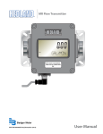
HI-3510
RF Radiation Badge
Broadband Electromagnetic
Radiation Detector
User’s Manual
Copyright
© 1996 by Holaday Industries, Inc.
Manual #600071 10/97
$20.00
Archived 4/2/10
Revision Record
Manual #600071
HI-3510 Radiation Badge
Broadband Electromagnetic Radiation Detector
Revision
--A
Description
Release
Added CE Label
Date
11-6-96
10-10-97
Archived 4/2/10
TABLE OF CONTENTS
PAGE
WARNING . . . . . . . . . . . . . . . . . . . . . . . . . . . . 1
SECTION I
1-1
INTRODUCTION . . . . . . . . . . . . . . . . 3
General . . . . . . . . . . . . . . . . . . . . . . 3
SECTION II
SPECIFICATIONS . . . . . . . . . . . . . . . 5
SECTION III
3-1
3-2
3-3
3-4
3-4-1
3-4-2
3-4-3
3-4-3-1
3-4-3-2
3-4-4
3-4-5
OPERATION . . . . . . . . . . . . . . . . .
General Information . . . . . . . . . . .
Safety Precautions. . . . . . . . . . . . .
Operating Controls and Indicators. .
Operating Procedure . . . . . . . . . . .
Set-Up Mode . . . . . . . . . . . . . . . .
Setting Alarm Warning Level . . . . .
Measurement Modes . . . . . . . . . . .
"Average” Measurement Mode . . . .
"Instantaneous" Measurement Mode
Latched Alarm . . . . . . . . . . . . . . .
Built-In Test Functions . . . . . . . . . .
SECTION IV
4-1
4-2
4-3
4-4
THEORY OF OPERATION
General . . . . . . . . . . . .
Magnetic Field Sensor . .
DC Circuit . . . . . . . . . .
RF Shielding . . . . . . . .
.
.
.
.
.
.
.
.
.
.
.
.
.
.
.
.
.
.
.
.
.
.
.
.
.
.
.
.
.
.
.
.
.
.
.
SECTION V
5-1
5-2
5-3
MAINTENANCE . . .
General . . . . . . . . .
Battery Replacement
Trouble Shooting . .
SECTION VI
6-1
6-2
6-3
.
.
.
.
.
.
.
.
.
.
.
.
.
.
.
.
.
.
.
.
.
.
.
.
7
7
7
8
8
11
11
11
12
12
13
13
.
.
.
.
.
.
.
.
.
.
.
.
.
.
.
15
15
15
15
16
.
.
.
.
.
.
.
.
.
.
.
.
.
.
.
.
.
.
.
.
.
.
.
.
.
.
.
.
.
.
.
.
.
.
.
.
.
.
.
.
.
.
.
.
.
.
.
.
.
.
.
.
17
17
17
18
CALIBRATION . . . . .
General . . . . . . . . . .
Calibration Procedure
Test Data Sheet . . . .
.
.
.
.
.
.
.
.
.
.
.
.
.
.
.
.
.
.
.
.
.
.
.
.
.
.
.
.
.
.
.
.
.
.
.
.
.
.
.
.
.
.
.
.
.
.
.
.
19
19
19
22
Archived 4/2/10
LIST OF TABLES
TABLE
1
TITLE
MODEL HI-3510 TECHNICAL SPECIFICATIONS
PAGE
5
LIST OF ILLUSTRATIONS
FIGURE
1
TITLE
PAGE
MODEL HI-3510 DISPLAY . . . . . . . . . . . . . . . 10
Archived 4/2/10
Limited Warranty
Holaday Industries, Inc. warrants each model HI-3510 Radiation
Badge Broadband Electromagnetic Radiation Detector to be free
from defects in material and workmanship for a period of one
year from the date of shipment to the purchaser. This warranty
extends to the original purchaser only, and does not apply to the
batteries or to any products or parts subject to misuse, neglect,
accident, unauthorized service or abnormal conditions of
operation.
In the event an instrument covered by this warranty fails,
Holaday Industries, Inc. will, without charge, repair and
recalibrate the instrument if returned to their factory within one
year of the original purchase—provided that Holaday Industries'
examination discloses, to its satisfaction, that the product is
defective. Holaday Industries, Inc., may, at its option, replace
the product in lieu of repair. If the defect was caused by misuse,
neglect, accident, unauthorized service or abnormal conditions of
operation, repairs will be billed at a nominal cost. In such cases,
an estimate will be provided before work is started, if requested
by the purchaser.
For warranty service, contact Holaday Industries, Inc. Provide
the serial number of the instrument and complete details
regarding the failure mode. You will then be given either service
information or shipping instructions. Return the instrument to
the factory, transportation prepaid. Repairs will be made at the
factory and the instrument will be returned to you, transportation
prepaid. Holaday Industries, Inc., assumes no responsibility for
loss of, or damage to, products in transit.
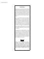
Warning!
EXTREME CAUTION IS ADVISED WHEN WORKING IN
ENVIRONMENTS WHERE HIGH-INTENSITY ELECTROMAGNETIC
FIELDS MAY EXIST AND WHERE CONTACT WITH HIGH VOLTAGE
OR HIGH CURRENT CIRCUITS OR APPARATUS IS POSSIBLE.
ACCIDENTAL CONTACT WITH OBJECTS OR CIRCUITS OPERATING
AT HIGH VOLTAGES OR HIGH CURRENTS CAN BE LETHAL!
HOLADAY INDUSTRIES, INC. ASSUMES NO LIABILITY FOR ANY
Archived 4/2/10
HIn3510 Manual
Page — 1
WARNING:
Harmful effects may result from exposure to
electromagnetic (EM) radiation in the frequency range
from 300 kHz to 100 Ghz.
Among the more widely accepted safety standards are
those established by the American National Standards
Institute ("ANSI"), C95.1-1991, and the National
Radiological Protection Board (“NRPB”), NRPB-G11, of
the United Kingdom. Each of the two standards
establishes different safety limits for the general public
and industrial environments. Of particular significance is
the 10 to 300 MHz frequency range, where the limits are
most stringent, especially for the general public, and are
set to an equivalent power density of 0.2 mW/cm2. At
higher frequencies, the limits are as high as 1 mW/cm2,
whereas at frequencies below 3 MHz, the limits are set to
100 mW/cm2.
Note that the aforementioned safety standards cannot be
measured by the Model H600A, which is a warning, and
not a measuring device. Suitable measuring devices exist
in the marketplace. Please contact the factory for
additional information on this subject.
The three common units of measurement for
characterizing electromagnetic energy are power density
in mW/cm2, electric field ("E-field") in V/m and magnetic
field ("Hfield") in A/m. At sufficiently large distances
from the source of radiation, the E-field and H-field
components have a fixed mathematical relationship.
Thus, the measurement of any one of these units in free
space is sufficient to determine the radiation level and
derive the other two. At frequencies nominally above 1
Archived 4/2/10
Page — 2
HIn3510 Manual
GHz, most radiation fields are of this character known as
the free space condition. The free space relationships are
shown below:
To convert:
Power Density P in mW/cm2 to Electric
Field E in V/m:
E=61.4 (P0.5)
Power Density P in mW/cm2 to
Magnetic Field H in A/m:
H=0.163 (P0.5)
Always approach an unknown field cautiously, starting
from as far away as possible and extending the RF
Radiation Badge at arm's length toward the energy
source. Allow two to three seconds for the instrument to
respond. Observe all safety precautions. Do not walk
into a suspected radiation field until the power density is
determined to be safe. Ensure that the unit is in the
"Instantaneous" Measurement Mode (see paragraph 3-43-2), not the "Average" Measurement Mode.
Archived 4/2/10
HIn3510 Manual
Page — 3
SECTION I
INTRODUCTION
1-1
General
The Model HI-3510 Broadband Electromagnetic Radiation
Detector (see figure 1) is a portable, battery operated,
non-ionizing radiation hazard detector intended for
personal use. It detects electromagnetic radiation from
RF and microwave sources in the frequency range from
0.05 to 2.5 GHz and alerts the user to potentially
hazardous fields. The Model HI-3510 enables the user to
set the alarm warning level anywhere in the range from
0.2 to 20 mW/cm2. In addition, the user can choose
either of two measurement modes: instantaneous
exposure level or a six minute average measurement.
Both modes are displayed on a three digit LCD panel
along with a ten segment bar graph normalized to the
selected alarm warning level. Electrical, mechanical and
performance characteristics are described in table 1
below.
The Model HI-3510 is intended for use by personnel who
work with or service RF and microwave equipment such
as:
Ž Microwave Ovens
Ž Medical Equipment
Ž Microwave Heaters and Dryers
Ž Communication Systems
Ž Cellular Telephones
Archived 4/2/10
Page — 4
HIn3510 Manual
Archived 4/2/10
HIn3510 Manual
Page — 5
SECTION II
SPECIFICATIONS
FEATURE
DESCRIPTIVE DATA
FREQUENCY RANGE:
50 MHZ TO 2.5 GHz
POWER DENSITY RANGE:
0.01 TO 20 mW/cm2
ALARM ACCURACY:
±2 dB
RESPONSE:
Isotropic
RF DETECTION:
Diode
AVERAGE POWER
OVERLOAD:
1 W/cm2
PEAK POWER OVERLOAD:
100 W/cm2
POWER DENSITY
INDICATORS:
A) 3 Digit LCD
B) Bar Graph
MEASUREMENT MODES:
A) Instantaneous Power
Density
B) 6 Minute Average
Power Density
BAR GRAPH DISPLAY:
Percent of Set Alarm Level
ALARM LEVEL SETTINGS:
0.2 to 20 mW/cm2
ALARM SIGNALS:
A) Flashing LCD Indicator
B) Flashing LED
C) Audible Beep
BUILT IN TEST:
Continuous
BUILT IN TEST
FUNCTIONS:
A) Detector Fault
B) Low Battery
TEMPERATURE RANGE:
Operating
Storage
10/C to + 55/C
40/C to + 65/C
Table 1
Model HI-3510 Technical Specifications
Archived 4/2/10
Page — 6
HIn3510 Manual
Archived 4/2/10
HIn3510 Manual
Page — 7
SECTION III
OPERATION
3-1
General Information
The Model HI-3510 can be carried inside outer garments,
fastened to a shirt or jacket pocket, or to a belt using the
clip provided on the instrument. Metallic objects such as
a belt buckle, pen, pencil, etc., could affect the accuracy
of the Model HI-3510. Do not locate the unit near any
metallic object.
NOTE:
The side of the unit containing the clip should always
face toward the wearer's body.
3-2
Safety Precautions
The following precautions should be observed when
entering an area where unsafe radiation levels may be
expected.
1.
2.
3.
Turn on the Model HI-3510. Set it to the
"Instantaneous" Measurement Mode as described
in paragraph 3-4-3-2.
Enter the area and do a "walk-around". Should
the Model HI-3510 indicate that an alarm
condition exists, take corrective action by turning
off the source of RF power or leaving the area
immediately.
Keep the Model HI-3510 turned on and continue
to wear it as long as you are in the area.
Archived 4/2/10
Page — 8
3-3
HIn3510 Manual
Operating Controls and Indicators
The operating controls on the Model HI-3510 are the ONOFF switch and the MODE switch, both of which are
located on the side of the unit. In addition, the Model HI3510 has three alarm indicators: Two visual indicators
consisting of an LCD display panel and red LED warning
light, both located on the top of the unit (see figure 2),
and an audible alarm produced by a beeper located with
the unit. In addition, there is an audio output jack to
which the furnished acoustical earpiece can be
connected.
3-4
Operating Procedure
To turn the unit ON, place the ON-OFF switch in the ON
position. The unit will respond with a three second beep
and its red LED will glow to confirm that the unit is
operational. In addition, all segments of the LCD display
will be on during this three second interval. The LCD
display will then indicate the preset alarm warning level
for about seven seconds. The unit will then respond with
a short beep and red LED flash. At this time; the unit is
operational and will indicate the power density in the area
as well as the ratio of the power density in the area to
the preset alarm warning level (% ALARM LEVEL bar
graph). This display is normalized to the programmed
alarm level so that the alarm indicates when the bar
graph reaches 100%. Using this display, the wearer can
tell how close he or she is to the alarm without being
exposed to an alarm power level. (If you are working in
a noisy environment, connect the acoustical earpiece to
ensure hearing the audible alarm.) When there are no RF
fields present higher than the preset alarm warning level,
there will be no further alarm indications from the unit.
Archived 4/2/10
HIn3510 Manual
Page — 9
Should the unit detect a field that exceeds the preset
alarm warning level, the unit will start to beep and flash.
The beep and the flash rate are directly proportional to
the RF field strength above the alarm set value (see 3-42). Note that once the alarm starts, it will latch at the
minimum flash rate, continuing to warn of an overexposure even if the RF field that caused the alarm is no
longer present. In order to reset the alarm function, the
unit must be turned OFF and back ON using the ON-OFF
switch. For information concerning disabling the latch
function, refer to paragraph 3-4-4. For information
concerning "Instantaneous" vs "Average" measurement
modes, refer to paragraph 3-4-3.
Archived 4/2/10
Page — 10
HIn3510 Manual
HI-3510 Display Features
FIGURE 1
MODEL HI-3510 DISPLAY
Archived 4/2/10
HIn3510 Manual
Page — 11
3-4-1 Set-Up Mode
The "Set-up" mode is used to set the alarm warning level
and to enable/disable the audible alarm. To enter this
mode, set the "ON-OFF" switch to ON. Then depress the
MODE switch after the initial three second period
referenced in paragraph 3-4. The LCD display will
indicate "S.U.". At this point, the alarm warning level
can be changed (paragraph 3-4-2).
3-4-2 Setting Alarm Warning Level
In the "Set-Up" mode (paragraph 3-4-1), depress and
hold the MODE switch. After three seconds, the preset
alarm warning level will be displayed. Release the MODE
switch. Depressing and holding the MODE switch again
at this point will result in a rapidly increasing alarm
warning level indication. Continue to depress the MODE
switch until the desired alarm level is approached. Then,
release the MODE switch and pulse it at a convenient
rate until the desired alarm warning level is reached. Once
it is reached, set the ON-OFF switch to OFF and then to
ON again. The alarm warning level that has just been set
will remain in memory until changed again as described
above.
3-4-3 Measurement Modes
The Model HI-3510 Measurement Mode can be set to
either "Instantaneous" or "Average" by depressing and
releasing the MODE switch while the unit is in its normal
operating mode. See paragraphs 3-4-3-1 and 3-4-3-2.
Archived 4/2/10
Page — 12
3-4-3-1
HIn3510 Manual
“Average” Measurement Mode
When the AVG annunciator on the left side of the display
area is visible, a six-minute running average is maintained
by the unit. Power density is sampled every 3.6
seconds. During the first six minutes (i.e.-360 seconds
or 100 measurements), the running average of all
measurements taken will be displayed. After six minutes,
each "new" measurement will replace the measurement
taken 363.6 seconds prior to that "new" measurement.
Therefore, the average of the most recent 100
measurements will always be displayed.
The average of the latest 100 measurements is also
compared by the unit to the alarm warning level set by
the operator (paragraph 3-4-2) to determine the %
ALARM LEVEL ratio. (During the first six minutes of
operation, the running average of all measurements taken
will be compared by the unit to the alarm warning level
set by the operator to determine the % ALARM LEVEL
ratio.) If the % ALARM LEVEL ratio reaches 100%, the
unit's alarm circuitry will be activated, the red LED and
the ALARM annunciator on the LCD will flash every 3.6
seconds, and the audible alarm will sound every 3.6
seconds.
3-4-3-2
"Instantaneous" Measurement Mode
When the INST annunciator on the left side of the LCD
display area is visible, the measured power density is
sampled and displayed every 1.8 seconds. (Note that the
Model HI-3510 saves data for six minutes regardless of
the display selected. Switching between "Average" and
"Instantaneous" does not affect the data being stored.)
Archived 4/2/10
HIn3510 Manual
Page — 13
3-4-4 Latched Alarm
A feature of the unit's alarm system is that the beeps and
flashes are progressive. Once the alarm level has been
reached, the unit will indicate a single beep and flash
each 1.8 seconds with the "INST" annunciator displayed
or 3.6 seconds with the "AVG" annunciator displayed.
Should the unit detect a field that exceeds the preset
alarm level, the unit will start to beep and flash. The
beep and the flash rate are directly proportional to the RF
field strength. Note that once the alarms start, they latch
at the minimum flash rate, continuing to warn of an over
exposure situation even if the RF field that initially caused
the alarm is no longer present. In order to reset the alarm
function, it is necessary to turn the unit OFF and back ON
using the ON-OFF switch. If it is desired to disable the
latch function, follow the turn-on procedure described in
paragraph 3-4 except depress and hold the MODE switch
before placing the ON-OFF switch to the ON position.
3-4-5 Built-In Test Functions
The unit generates a beep and flash at turn on to verify
that the alarm indicators are functioning. At this time, all
segments of the LCD display are enabled to indicate that
the display is operating properly. Ten seconds after turn
on, the unit will generate a second beep and flash which
indicates that it is operational. A low battery condition is
indicated if the unit beeps and flashes two times after the
ten second period. To verify, check the LCD display for
a "BAT" indication. In addition, the battery condition is
tested automatically every minute. Should the battery
measure low, the "BAT" indicator will flash and the unit
will beep and flash once a minute. Refer to Section V for
battery replacement procedures.
Archived 4/2/10
Page — 14
HIn3510 Manual
The unit also contains continuous fault detection circuitry
to alert the user to an RF detector failure. In that event,
the beeper and light will start to beep and flash at a
constant rate, and the LCD display will indicate "FAIL".
The unit is no longer usable in this condition and should
be turned off and serviced.
Archived 4/2/10
HIn3510 Manual
Page — 15
SECTION IV
THEORY OF OPERATION
4.1
GENERAL
The Model HI-3510 is a portable, battery operated, nonionizing radiation hazard detector intended for personal
use. It detects electromagnetic radiation from RF and
microwave sources in the frequency range from 0.05 to
2.5 GHz and alerts the user to potentially hazardous
fields. The Model HI-3510 enables the user to set the
alarm warning level anywhere in the range from 0.2 to 20
mW/cm2. In addition, the user can choose either of two
measurement modes: instantaneous exposure level or a
six minute average measurement. Both modes are
displayed on a three digit LCD panel along with a ten
segment bar graph normalized to the selected alarm
warning level.
4.2
MAGNETIC FIELD SENSOR
The Model HI-3510 uses an isotropic array of tandem
loops, each feeding a Schottky diode detector. The
outputs of these loops are summed to a common feed
line. Utilizing a unique cancellation scheme, the resulting
rectified voltage represents only the magnetic field
component. The electric field component is canceled out
and does not appear in the measurement. The diodes are
operated in their low level region to assure square law
performance.
4-3
DC CIRCUIT
The DC output produced by the RF circuit is amplified by
a differential chopper-stabilized amplifier. This circuit has
Archived 4/2/10
Page — 16
HIn3510 Manual
high common mode rejection and low DC drift. The high
level output of this circuit is connected to a micro
controller which has a built in A/D converter. The
amplifier has two gain ranges that are controlled by the
micro controller.
A self-contained test signal is constantly applied to the
RF detector. Should a fault occur in this circuit, a fault
signal is generated through the DC amplifier which then
generates a fault bit to the micro controller.
The analog output from the DC amplifier is digitized by
the micro controller's A/D converter. The reference
voltage for the A/D converter is generated from a bandgap reference diode which provides excellent long term
stability.
The micro controller then controls the
measurement rate for instantaneous or average
measurements, amplifier ranges, LCD display, fault
indications and low battery signals. It stores and
computes the data for the six minute average readout and
stores the alarm warning level trip point.
4-4
RF SHIELDING
To enable accurate operation of the sensitive circuits
within the RF Radiation Badge in the presence of RF
fields, an array of shields and absorbers is used. The
circuits are contained within a Faraday shielded area
which is then covered by a graded absorber to minimize
field disturbances.
Archived 4/2/10
HIn3510 Manual
Page — 17
SECTION V
MAINTENANCE
5-1
GENERAL
The Model HI-3510 been designed for rugged field use.
Normal maintenance for this unit consists only of battery
replacement and calibration.
5-2
BATTERY REPLACEMENT
The unit comes furnished with a D12450B lithium cell.
Normal operating life is 1000 hours. With the alarm in its
latched mode, the battery life is about 80 hours. The
shelf life of the battery is about ten years when stored in
a cool environment.
The unit has a built in battery monitoring circuit that
generates a single beep and flash at one minute intervals
under low battery conditions. To replace the battery,
proceed as follows:
1.
Turn the unit off. THIS IS IMPORTANT.
2.
Slide open and remove the battery cover.
3.
Note the position of the battery and the battery
removal strap. To remove the battery, pull the
strap straight out until the battery can be
removed.
4.
Insert the new battery, making sure the new
battery and the battery removal strap are in the
positions noted in step 3 above.
5.
Turn the unit on. The instrument should now be
operational and the one minute beep and flash
Archived 4/2/10
Page — 18
HIn3510 Manual
warning indicators should cease.
5-3
TROUBLE SHOOTING
NOTE:
In general, except for normal battery replacement, trouble
shooting and repair of this instrument by the user is not
recommended.
5-3-1
As part of its self-test capability, the unit will produce a
tone and flash when it is turned on. In the event it fails
to do so, check the condition of the battery by replacing
it in accordance with the procedure described in
paragraph 5-2 above.
Should the unit continue to malfunction, return it to
Holaday Industries for repair.
Archived 4/2/10
HIn3510 Manual
Page — 19
SECTION VI
CALIBRATION
6-1
GENERAL
The Model HI-3510 should be calibrated at 12 month
intervals. To do so requires the use of highly specialized
test equipment and facilities, such as a radio-frequency
anechoic chamber and TEM cells, wherein fields of
known power density can be accurately established. It
should also be noted that to establish the required power
densities will require CW sources of 10W or greater
together with accurately calibrated test antennas and
power monitoring equipment. If facilities of this type are
not available, the unit should be returned to Holaday
Industries or to another qualified calibration facility for
this service.
6-2
CALIBRATION PROCEDURE
6-2-1
Set the alarm warning level to 0.5 mW/cm2 as
described in paragraph 3-4-2.
6-2-2
Disable the latch function as described in
paragraph 3-4-4.
6-2-3
Following the procedures described below,
position the unit in a 50 - 500 MHZ TEM cell and
in a 900 MHZ to 2.5 Ghz anechoic chamber.
The preferred orientation of the E-field is parallel
to the vertical axis of the unit.
6-2-4
At each test frequency, raise the power density
level at the unit until an alarm is indicated.
Record this power density level on the test data
sheet in mW/cm2.
Archived 4/2/10
Page — 20
6-2-5
HIn3510 Manual
Perform the test described in paragraph 6-2-4 as
follows:
In the TEM cell, test at 50, 300 and 500 MHZ
In the anechoic chamber, test at 0.9, 1.2 and 2.5
GHz
6-2-6
From the data in paragraph 6-2-5, calculate the
average power density measured over the band
by taking the square root of the product of the
highest and lowest readings recorded. Record
the resultant on the data sheet for P CAL.
6-2-7
Divide 0.5 mW/cm2 by the power density level
recorded on the data sheet for P CAL. This
determines the correction multiplier, M.
6-2-8
Alignment can now be performed at any one of
the calibration frequencies specified in step 6-25. Select a convenient calibration frequency.
6-2-9
At the selected calibration frequency, multiply by
M the indicated power density from the data
recorded in paragraphs 6-2-4 and 6-2-5 above.
Record this as P REF.
6-2-10 Locate the calibration potentiometer access hole
behind the “Made in USA” label. Remove the
label only if adjustment is needed.
6-2-11 Apply the PREF power at the calibration frequency.
Adjust this potentiometer such that the alarm just
starts to indicate. Repeat this adjustment as
required.
6-2-12 This completes the RF calibration. Replace the
“Made in USA” label. Attach a new calibration
Archived 4/2/10
HIn3510 Manual
Page — 21
sticker with the current calibration date.
NOTE:
Do not place any stickers or labels that contain metal on
the bottom surface of the unit or the lower portions (i.e.,
approximately 1 ½ inches up from the bottom surface) of
the front and both sides of the unit. This could seriously
affect the accuracy of the unit. Paper or plastic stickers
are acceptable.
Archived 4/2/10
Page — 22
6-3
HIn3510 Manual
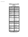
TEST DATA SHEET MODEL HI-3510
DATE
SERIAL NUMBER
TESTED BY
PARA 6-2-4 AND 6-2-5
FREQUENCY
(GHz)
POWER DENSITY LEVEL (mW/cm2)
0.05
0.3
0.5
0.9
1.2
2.5
PARA 6-2-6
PARA 6-2-7
PCAL = (PHI PLO)0.5 =
M = 0.5
PCAL
=
PARA 6-2-8
CAL FREQ =
PARA 6-2-9
PREF = M (POWER DENSITY
=
AT CAL FREQ)
PARA 6-2-11
ALARM SET FOR PREF
CHECK
Archived 4/2/10
HIn3510 Manual
Page — 23
--NOTES--
Archived 4/2/10
Page — 24
HIn3510 Manual
--NOTES--


![- [ [ [ ANSEL ] ] ]](http://vs1.manualzilla.com/store/data/005876018_1-a636cab6934c7a831e92a71c6eb2f063-150x150.png)