1
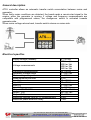
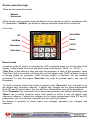
USER MANUAL
ATS-I
Tecnoelettra srl
Dal 1985
Via Vioni Dimo,5 42016 S.Rocco di Guastalla (RE)
Tel.+39.0522.832004
– Fax.+39.0522.832012
P.1/17
P1/17 ATS-I User manual
Tecnoelettra_EN.doc
Internet :www.tecnoelettra.it E-mail:[email protected]
Index
General description ........................................................................................................... 3
Electrical specifics ............................................................................................................. 3
Device operative logic ....................................................................................................... 4
Manual mode ................................................................................................................. 4
Automatic mode............................................................................................................. 5
Alarms ........................................................................................................................... 5
Display........................................................................................................................... 6
Automatic transfer switch procedure mains-generator, generator-mains........................ 8
Parameters Programmation ......................................................................................... 10
Phase detection special function.................................................................................. 12
Mechanical Sizing ........................................................................................................... 13
Rear View........................................................................................................................ 14
Triple phase wiring diagram (230Vac, 400Vac, 440Vac) ................................................. 15
Single phase wiring diagram (230Vac) ............................................................................ 16
Tecnoelettra srl
Dal 1985
Via Vioni Dimo,5 42016 S.Rocco di Guastalla (RE)
Tel.+39.0522.832004
– Fax.+39.0522.832012
P.2/17
P2/17 ATS-I User manual
Tecnoelettra_EN.doc
Internet :www.tecnoelettra.it E-mail:[email protected]
General description
ATS-I controller allows an automatic transfer switch commutation between mains and
generator.
When faulty mains conditions are detected, the board sends a remote start signal to the
engine; when the generator is running, if voltage and frequency measurements are
compatible with programmed values, the changeover switch is activated towards
generator side.
When mains voltage returns back, transfer switch returns on mains side.
Electrical specifics
Supply voltage (isolated)
Voltage measurements
Frequency measurements
Generator voltage range
Mains voltage range
Measurements precision
Input LA
Input LM
Input LR
Input LG
Output START GEN.
Output TLR
Output TLG
Maximum reaction time for VF measurements
Maximum phase detection delay
Tecnoelettra srl
Dal 1985
8 ÷ 30 Vdc
230Vac 1ph
230Vac 3ph
400Vac 3ph
440Vac 3ph
45 ÷ 65 Hz
0 ÷ 500 Vac
0 ÷ 500 Vac
± 2%
10 ÷ 30 Vdc
10 ÷ 30 Vdc
0 ÷ 500 Vac
0 ÷ 500 Vac
5A, 10 ÷ 30 Vdc
5A, 230 Vac
5A, 230 Vac
2 sec.
1 sec.
Via Vioni Dimo,5 42016 S.Rocco di Guastalla (RE)
Tel.+39.0522.832004
– Fax.+39.0522.832012
P.3/17
P3/17 ATS-I User manual
Tecnoelettra_EN.doc
Internet :www.tecnoelettra.it E-mail:[email protected]
Device operative logic
There are two operative modes:
- Manual
- Automatic
At the startup, device selects automatically the correct operative mode in accordance with
P13 parameter; “Aut/Man” key allows to change operative mode without restriction.
Front view:
UP
Select Mis
Aut/Man
Down
Generator
LOCK
Start Gen
Mains
Manual mode
In manual mode all system is controlled by ATS-I operative panel, on the left side of the
display, a label shows the actual operative mode of the device (“ MAN “ or “ AUTO “).
“Start Gen” button allows to start and stop the generator; in case of idle generator, when
“Start Gen” button is pushed, a blinking key icon will appear near “MAN” indicator to signal
a starting phase for generator; when running engine is detected, the key become
permanent. To stop the engine “Start Gen” key must be pushed again ( key icon will
disappear).
To switch contactor status from mains to genset, push “Generator” key: Generator icon
will appear near frequency indicator, if genset line voltages are not within programmed
limits (P5 and P6 parameters), the icon will blink; otherwise the icon will be permanent.
Push “Generator” key a second time to disconnect generator line without switching; push
“Mains” key to switch contactor status from genset to mains, a icon will appear near
frequency indicator, if mains line voltages are not within programmed limits (P3 and P4
parameters), the icon will blink; otherwise the icon will be permanent.
On display is possible to check mains line voltages, generator line voltages and
frequency.
Tecnoelettra srl
Dal 1985
Via Vioni Dimo,5 42016 S.Rocco di Guastalla (RE)
Tel.+39.0522.832004
– Fax.+39.0522.832012
P.4/17
P4/17 ATS-I User manual
Tecnoelettra_EN.doc
Internet :www.tecnoelettra.it E-mail:[email protected]
To read mains voltages, push “Select Mis” key until “L” indication will appear on the left
upper corner; at this point mains voltages will be showed on display. Push “Select Mis”
again and “G” icon will appear; generator line voltages will replace mains measure. If
generator is not running, “OFF” icon will appear which means unavailable genset
measurements.
In manual mode, operative generator alarms are not detected, are available only
indicators LA and LM.
Automatic mode
Automatic mode allows to manage engine and transfer switch completely by software
logic, it’s not possible to start the generator or force switching through operative board,
“AUTO” indication will appear on the low left corner.
However with “Select Mis” is still possible to change displayed measurements from
generator and mains. When controller commands switching on mains or generator,
automatically values visible on display change in accordance.
Each phase is checked separately, so a phase failure will start the automatic intervention
procedure.
Alarms
If mains measurements are selected, in case of alarm will be possible to see one of these
messages on the left side of the display :
- “LOW VOLT” line voltage below programmed threshold ( P3 parameter );
- “HIGH VOLT” line voltage over programmed threshold ( P4 parameter );
Both alarms cause an automatic intervention procedure.
With running generator, after programmable timer ( P8 parameter), the controller checks
voltage status measured on alternator and in case of anomaly, one of these alarms will be
showed on display:
- “ERROR 1” if generator’s phase voltage is out of limits. ( P5, P6 parameters ).
- “ERROR 2” if generator’s frequency is out of limits. ( P12 parameter ).
- “ERROR 3” if generator fails to start.
If generator is working correctly, “ERROR 1” or “ERROR 2” alarms are showed if voltage
or frequency values are out of limits for the duration of programmed time ( P15 parameter)
To reset an alarm on display must be used “Aut/Man” key. The device returns on mains
position and restarts commutation procedure towards generator. If generator alarm is
active and mains voltage returns back, automatically the commutation will be switched on
mains side.
Tecnoelettra srl
Dal 1985
Via Vioni Dimo,5 42016 S.Rocco di Guastalla (RE)
Tel.+39.0522.832004
– Fax.+39.0522.832012
P.5/17
P5/17 ATS-I User manual
Tecnoelettra_EN.doc
Internet :www.tecnoelettra.it E-mail:[email protected]
Display
Display shows following indications:
Line 1:
(Example “G400 L1 L2 L3”) this code indicates which line is measured and
the connection type for the device.
L230M Mains, 230Vac single phase connection
L230
Mains, 230Vac three-phase connection
L400
Mains, 400Vac three-phase connection
L440
Mains, 440Vac three-phase connection
G230M Generator, 230Vac single phase connection
G230
Generator, 230Vac three-phase connection
G400
Generator, 400Vac three-phase connection
G440
Generator, 440Vac three-phase connection
Below the code are displayed the values of measured line voltage.
Line 2:
(Example “Vac 384 387 383”) On this line are showed the values of three
measured voltages, at the beginning of the line is displayed the unit of
measure .
Line 3:
(Example “Hz 48 |
“) on this line is showed frequency value (Hz)
measured on generator’s phase 1, then after separation bar “ | “ some status
symbols are displayed.
Generator symbol: is used when commutation is on generator
side, the icon blinks if measured values are out of limits.
Is alternative with Mains symbol.
Mains symbol: is used when commutation is on mains side,
the icon blinks if measured values are out of limits.
Is alternative with Generator symbol.
Pad lock symbol: is used when the keyboard is locked by
“LOCK” button keep pushed for more than 5 seconds, to
unlock the keypad, the procedure must be repeated.
Tecnoelettra srl
Dal 1985
Via Vioni Dimo,5 42016 S.Rocco di Guastalla (RE)
Tel.+39.0522.832004
– Fax.+39.0522.832012
P.6/17
P6/17 ATS-I User manual
Tecnoelettra_EN.doc
Internet :www.tecnoelettra.it E-mail:[email protected]
Symbol input LA active: the symbol is connected with LA input
which usually means a generator alarm.
Symbol input LM active: the symbol is connected with LMA
input which means running engine.
Line 4:
On this line are showed information about device’s operative modes.
All available information are listed below:
AUTO
Indicates automatic operative mode, alternative with
MAN and PROG.
MAN
Indicates manual operative mode, alternative with
AUTO and PROG.
PROG
Indicates programmation mode, alternative with MAN
and AUTO.
When MAN or AUTO modes are selected, indicates
running generator, blinking during start phase.
When AUTO mode is selected, indicates the
programmed delay time between faulty mains and
starting generator (P7 parameter) .
Pxx xxx:xxx When PROG mode is selected, indicates parameter
type “Pxx” and blinks to show that the parameter is
going to be modified, the old values ( “xxx:” ) is
showed on the left side of the colon, the new one
( “:xxx” ) on the right side.
Error
When AUTO mode is selected, alarm messages are
message
displayed in accordance with chosen visualization:
“L” or “G”.
Tecnoelettra srl
Dal 1985
Via Vioni Dimo,5 42016 S.Rocco di Guastalla (RE)
Tel.+39.0522.832004
– Fax.+39.0522.832012
P.7/17
P7/17 ATS-I User manual
Tecnoelettra_EN.doc
Internet :www.tecnoelettra.it E-mail:[email protected]
Automatic transfer switch procedure mains-generator, generator-mains
Initial configuration with mains OK (voltage values inside programmed thresholds)
R = Mains
G = Generator
Delay P11
Mains OK
TLR closed
TLG open
START GEN open
Mains KO +
Delay P7
Mains coupling
Starting engine
TLR closed
TLG open
START GEN closed
TLR closed
TLG open
START GEN closed
Generator OK +
Delay P9
Delay 500ms
Switching R-G
Switching G-R
TLR open
TLG open
START GEN closed
TLR closed
TLG open
START GEN closed
Mains OK +
Delay P10
Generator OK
TLR open
TLG closed
START GEN closed
Delay 500ms
When mains voltage is outside programmed limits (P3 and P4 parameters) for a delay
time (P7 parameter), the intervention process starts; at the end of this period, the engine
is started too and the controller waits for stable measurements for a delay time (P8
parameter), otherwise a “ERROR 3” message will be displayed.
With stable voltage and frequency values, after a delay time (P9 parameter) the
commutation is switched on generator side; between mains contactor opening and
generator contactor closure there is constant delay time of 500ms.
Transfer switch remains on generator side until mains voltage returns in a stable way in
accordance with programmed delay time (P10 parameter).
Tecnoelettra srl
Dal 1985
Via Vioni Dimo,5 42016 S.Rocco di Guastalla (RE)
Tel.+39.0522.832004
– Fax.+39.0522.832012
P.8/17
P8/17 ATS-I User manual
Tecnoelettra_EN.doc
Internet :www.tecnoelettra.it E-mail:[email protected]
With mains ok, generator contactor opens and after 500ms mains contactor is closed.
After cooling time (P11 parameter) the generator is stopped.
With running generator, if voltage and frequency value are outside programmed
thresholds ( P5, P6 and P12 parameters) for a delay time (P15 parameter), the device will
show an error message and the generator is turned off. In this case with “Aut/Man” key or
when mains returns back, the device returns to the mains OK status where generator
contactor is opened and mains contactor is closed.
Tecnoelettra srl
Dal 1985
Via Vioni Dimo,5 42016 S.Rocco di Guastalla (RE)
Tel.+39.0522.832004
– Fax.+39.0522.832012
P.9/17
P9/17 ATS-I User manual
Tecnoelettra_EN.doc
Internet :www.tecnoelettra.it E-mail:[email protected]
Parameters Programmation
Parameters programmation can be performed without operative mode restriction. Hold
“UP” and “DOWN” keys at the same time for 5 seconds to open programmation menu; the
word “PROG” will be displayed with the indication relative to P1 parameter, with “UP” and
“DOWN” keys is possible to scroll all parameters and select the one you need to change
with “Select Mis” button. The chosen parameter begins to blink and will be possible to
edit the value with “UP” or “DOWN” keys. Each increase/decrease command, the value
will be modified by 1 unit. Hold the button to raise inc/dec speed by 1 unit every 500ms,
and after 30 step, by 10 units every second. The old values ( “xxx:” ) is showed on the left
side of the colon, the new one ( “:xxx” ) on the right side.
To confirm the new value push “Select Mis” key, the parameter finish to blink and will be
possible to select another value. To exit programmation mode and save changes made,
hold “UP” and “DOWN” keys at the same time for 5 seconds.
Below a comprehensive list with all parameters.
P2
Values range
(unit)
230M, 230, 400,
440(V)
50, 60(Hz)
Default
values
400(V tri
phase)
50(Hz)
P3
0 ÷ -40(%)
-15(%)
P4
0 ÷ +40(%)
+15(%)
P5
0 ÷ -40(%)
-15(%)
P6
0 ÷ +40(%)
+15(%)
P7
P8
P9
P10
P11
P12
1 ÷ 600(s)
0 ÷ 600(s)
1 ÷ 240(s)
1 ÷ 240(s)
1 ÷ 240(s)
1 ÷ 5(Hz)
0(Automatic)
1(Manual)
0(pad lock)
1(pad unlock)
5(s)
120(s)
5(s)
10(s)
30(s)
5(s)
Par.
P1
P13
P14
Operative mode selection at start up
0
Pad lock at start up
1 ÷ 10(s)
3(s)
P16
0(Enable)
1(Disable)
0
Dal 1985
Mains system type, shows nominal voltage and
“M” symbol which indicates single phase system.
Mains nominal frequency
Minimum mains voltage (percentage over nominal
value)
Maximum mains voltage (percentage over nominal
value)
Minimum generator voltage (percentage over
nominal value)
Maximum generator voltage (percentage over
nominal value)
Generator start delay
Maximum engine running detection time
Switching on generator delay
Switching on mains delay
Generator cooling time
Generator frequency range
0
P15
Tecnoelettra srl
Description
Faulty mains / faulty generator delay. An alarm
generating condition must be detected for this time
long.
Phase detection function
Via Vioni Dimo,5 42016 S.Rocco di Guastalla (RE)
Tel.+39.0522.832004
Fax.+39.0522.832012
P10/17 ATS-I User–manual
Tecnoelettra_EN.doc P.10/17
Internet :www.tecnoelettra.it E-mail:[email protected]
Voltage threshold limits change with 1% step, delay time change with 1s step, frequency
range change with 1 Hz step, all other parameters have editing step in accordance with
their range values.
Tecnoelettra srl
Dal 1985
Via Vioni Dimo,5 42016 S.Rocco di Guastalla (RE)
Tel.+39.0522.832004
Fax.+39.0522.832012
P11/17 ATS-I User–manual
Tecnoelettra_EN.doc P.11/17
Internet :www.tecnoelettra.it E-mail:[email protected]
Phase detection special function
Phase detection function can be enabled for both mains and generator three-phase
systems with a special parameter ( P16 parameter).
This function works only with manual mode and three-phase system; this function allows
to check if each phase is detected correctly and if the phase sequence is the proper one.
In case of anomaly on display will be showed this message: “PH.SEQ.ERR”, this alarm
disable the closure of respective contactor ( G or L ). To reset the alarm can be used
“Select Mis” key. After the device repeats the whole control and switching procedure.
Tecnoelettra srl
Dal 1985
Via Vioni Dimo,5 42016 S.Rocco di Guastalla (RE)
Tel.+39.0522.832004
Fax.+39.0522.832012
P12/17 ATS-I User–manual
Tecnoelettra_EN.doc P.12/17
Internet :www.tecnoelettra.it E-mail:[email protected]
Mechanical Sizing
Tecnoelettra srl
Dal 1985
Via Vioni Dimo,5 42016 S.Rocco di Guastalla (RE)
Tel.+39.0522.832004
Fax.+39.0522.832012
P13/17 ATS-I User–manual
Tecnoelettra_EN.doc P.13/17
Internet :www.tecnoelettra.it E-mail:[email protected]
Rear View
GEN.INPUT
T
-
+
LA
S
R
L
N
MAINS.INPUT
T
S
R
L
N
LM
8-30VDC
START
GEN.
Tecnoelettra srl
Dal 1985
TLR
TLG
LR
LG
230-440VAC
230-440VAC
Via Vioni Dimo,5 42016 S.Rocco di Guastalla (RE)
Tel.+39.0522.832004
Fax.+39.0522.832012
P14/17 ATS-I User–manual
Tecnoelettra_EN.doc P.14/17
Internet :www.tecnoelettra.it E-mail:[email protected]
Three-phase wiring diagram (230Vac, 400Vac, 440Vac)
Tecnoelettra srl
Dal 1985
Via Vioni Dimo,5 42016 S.Rocco di Guastalla (RE)
Tel.+39.0522.832004
Fax.+39.0522.832012
P15/17 ATS-I User–manual
Tecnoelettra_EN.doc P.15/17
Internet :www.tecnoelettra.it E-mail:[email protected]
Single phase wiring diagram (230Vac)
Tecnoelettra srl
Dal 1985
Via Vioni Dimo,5 42016 S.Rocco di Guastalla (RE)
Tel.+39.0522.832004
Fax.+39.0522.832012
P16/17 ATS-I User–manual
Tecnoelettra_EN.doc P.16/17
Internet :www.tecnoelettra.it E-mail:[email protected]
NOTES:
Tecnoelettra srl
Dal 1985
Via Vioni Dimo,5 42016 S.Rocco di Guastalla (RE)
Tel.+39.0522.832004
Fax.+39.0522.832012
P17/17 ATS-I User–manual
Tecnoelettra_EN.doc P.17/17
Internet :www.tecnoelettra.it E-mail:[email protected]