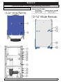
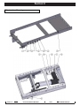
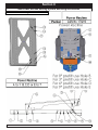
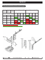
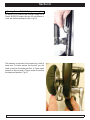
1
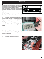
2009 Quickie Rhythm Service Manual Supplement
PG DRIVES TECHNOLOGY
R
©2009 Sunrise Medical Inc.
xxxxxx Rev A
Quickie Rhythm Service Manual Contents
Introduction ...................................................... 0.1
Basic Setup ..................................................... 0.2
Multimeter Tutorial ........................................... 0.3
Health and Safety ............................................ 0.5
Electro Static Discharge .................................. 0.8
Batteries .......................................................... 0.9
VR2 Remote Controller ................................. 0.12
VR2 Plugs/Connectors .................................. 0.13
VR2 -Main Wiring Diagrams .......................... 0.14
R-NET Remote Controller ............................. 0.16
R-NET Optional Electronics........................... 0.18
R-NET Plugs/Connectors .............................. 0.19
Main Wiring Diagram R-NET ......................... 0.21
Main Wiring Diagram R-net ........................... 0.22
Battery Connection Test ...................................1.1
Check Battery Wire Harness ............................1.2
Section 2
VR2 Remote Controller Display........................2.1
The Maximum Speed Indicator Ripples............2.1
The Maximum Speed Indicator Flashes ...........2.1
Battery Gauge is Steady...................................2.1
Battery Gauge Flashes Slowly .........................2.1
Battery Gauge Steps Up...................................2.1
Battery Gauge Blinks Once Every 2.5 Seconds
..........................................................................2.1
Battery Gauge Flashes Rapidly .......................2.1
VR 2 Remote & R-Net LED Controller Display .2.2
R-Net Color Joystick & OMNI Controller Display
Symbols ............................................................2.3
Section 3
VR2 Controller Diagnostic Codes .....................3.1
One Bar - Low Battery Voltage ) .......................3.1
Two Bars - Left Motor Disconnected ...............3.1
Three Bars - Left Motor Wiring Trip) .................3.2
Four Bars- Right Motor Disconnected ..............3.3
Five Bars - Right Motor Wiring Trip ..................3.4
Six Bars - Charger Connected..........................3.4
Seven Bars - Possible Joystick Trip ................3.4
Seven Bars + Speed Profile Indicator Communication Error ......................................................3.4
Eight Bars - Possible Control System Trip........3.5
Nine Bars - Solenoid Brake Trip .......................3.5
Ten Bars - High Battery Voltage ......................3.5
Section 4
R-net Troubleshooting Procedures .................. 4.1
Chair Will Not Power Up ...................................4.1
Section 5
R-net Fault Codes ........................................... 5.1
Power Chair Displays a Fault on the Hand Control or Omni .......................................................5.1
Table 1, Error Codes.........................................5.1
R-net Fault Codes cont.....................................5.3
Example of R-10 Fault Isolation .......................5.3
Power Chair Will Not Drive in Creep Speed when
Tilted .................................................................5.5
Tilt Will Not Operate .........................................5.6
Section 6
Troubleshooting Recline ..................................6.1
Power Chair Will Not Drive at Full Speed .........6.1
Troubleshooting Power Recline Calibration. ....6.2
Power Chair will not Drive in Creep Speed when
Reclined............................................................6.3
Power Recline does not Operate......................6.4
Power Shear Does not Operate .......................6.5
Section 7
Troubleshooting Power Legrest .......................7.1
Section 8
Seating System Mounting Instructions ............ 8.1
Non Tilt Module/Packer Interface .....................8.1
Seat to Tilt Mounting .........................................8.2
Seat to Tilt Mounting .........................................8.3
Tilt to Interface Mounting ..................................8.4
New Power Recline Seating System Mounting
Instructions ...................................................... 8.5
Seat to Recline Mounting .................................8.5
New Power Tilt & Recline Seating System Mounting Instructions ................................................ 8.6
Seat to Tilt/Recline Mounting: ...........................8.6
Seat to Floor Height Matrix ...............................8.7
Asap Fixed Center mount Footrest Mounting Matrix ...................................................................8.10
Adjusting Power ELR / ALR Legrest Length ... 8.11
Adjusting Power Recline Backrest..................8.13
Section 9
OBP Programming Quick Guide...................... 9.1
Introduction
Please read and follow instructions in this service manual before attempting to
troubleshoot or repair this product for the first time .If there is anything in this Service
Manual that is not clear, or if you require additional Technical assistance, contact
Sunrise Medical at: (800) 333-4000 option 2, then option 1.
Safely troubleshooting and/or repair of this product depends on your diligence in
following the instructions within this manual. Sunrise Medical is not responsible for
injuries or damage resulting from a person’s failure to exercise good judgement and/
or common sense.
There are warning symbols used in this document to focus
attention on any hazard that could effect the safety of the individual
troubleshooting the chairs covered in this Service Manual.
This Service Manual is intended as a troubleshooting guide for the Quickie Rhythm.
Photographs and content may differ from the actual products in some cases due to
changes in specifications and other factors.
This Service Manual is intended for use by persons with a basic working knowledge
and the skills required in servicing and maintaining Power Wheelchairs. Persons
without a General Working knowledge and expertise in the servicing of this product
should not carry out troubleshooting procedures. This can result in problems with
future servicing, and/or damage to the unit.
Parts and configuration or specifications of Products included in this Service Manual are
subject to change without prior notice.
For up to date parts and the latest version of this manual go to:
www.sunmed.com
and click on the Parts Search button
Click !
SUNRISE MEDICAL
RHYTHM SERVICE MANUAL
2009
PAGE 0.1
Basic Setup
When setting up the components of the chair, complete the following checklist to ensure proper and
safe operation of the equipment.
Check :
□ Are the batteries fully charged?
a. Test battery voltage with D.C. meter across the terminals of batteries. The measurement should
be above 12 volts D.C.
b. If not, fully charge the batteries.
□ Are all necessary power components installed and connected ?
a. Input device (normally Joystick)
b. Cable from Joystick to the Bus Line
c. Control Module; for the Rhythm located at back of chair behind shroud
□ Are all necessary connections fastened or inserted?
a. Battery connectors to the batteries
b. Cable between Joystick and the Control
c. Both Motor Connectors to the Control Module.
□ Is the Drive Gear engaged?
a. With the power off the chair should not move if pushed from behind.
b. If the chair moves when pushed, refer to proper operation of Drive Gear Engagement section.
□ Does Display light up when Power On/Off switch is depressed?
a. If no - recheck the 4 checks listed above then refer to the section on Diagnostics.
b. If yes – the Power Wheelchair is ready to drive
PAGE 0.2
RHYTHM SERVICE MANUAL
2009
SUNRISE MEDICAL
Multimeter Tutorial
MULTIMETER
The Multimeter
The multimeter is one of the most useful tools
in the toolbox. It can be used to check wires,
shorts, voltages, resistance, all manner of
electrical circuits. This tutorial is designed to
help clarify the symbols and socket options
The Probes
PROBES
found on various multimeters.
Probes connect the meter to the circuit. Simply touch them to the connections you want
to measure and read the display. Obviously,
this depends on how the meter is set up, and
what is being measured.
The Ports
1. The Common Port.
Generally, the black probe plugs in here
(negative) and as the name suggests, it’s
the common element to all of the testing
circuits. Think of it as the ground rail.
2. Voltage, Resistance and Continuity port.
This is commonly used option. Connect
the red (positive) probe to this port when
using any voltage readings, resistance
readings or when checking wire continuity (explained in more detail later in the
tutorial).
3. Current up to 300mA.
This port is used for “counting electrons”
in a circuit, and thus their rate of flow
(current being the flow of electrons).
You’ll notice that this side is “fused”, so
that you don’t end up melting the meter’s
circuits.
4. Current up to 10A.
Same as above, except it can take
more current, as the name suggests.
SUNRISE MEDICAL
RHYTHM SERVICE MANUAL
PORTS
2009
PAGE 0.3
Symbols
This section describes the basic symbols used in a typical
multimeter.
AC
This symbol means alternating current. Use this when you want to
test something that has AC current running through it. Typically you’d
want to test the voltage of an inverter (for cold cathodes or neons) or a
similar device.
DC
This means Direct Current. This is the type of electrical power produced by
a battery. With a battery connector, the black wire(s) should be connected to
the negative(-) terminal of the battery and should be considered the common
ground. The red wire(s) should be connected to the positive(+) terminal of the
battery and is considered the “hot” lead.
Voltage
This means Voltage or Potential Difference. This measures the potential
difference between the two probes. To measure voltage, connect the positive
probe to a port that is marked “V” or Voltage.
Note: “mV” means milli-volts .001 Voltage
Current
Technically, this term is incorrect. It should be “I” but since current is measured
in Amps and the readout value is in amps, the symbol makes sense. This
measures the current that is flowing through the part of the circuit between the
two probes (the meter itself). Typically, you need to plug the positive terminal
into a port marked “A” or Current. You need to put the meter “In Series” in the
circuit to use this feature correctly.
Resistance
This symbol means Resistance and is measured in Ohms. You can use this
setting to measure the resistance between two points; for example across a
piece of wire or a resistor (to check its value). If you don’t have a continuity
check, then this can be used to check for shorts. Any value below 0.05 Ohms
constitutes a short, meaning that whatever the probes are attached to is
connected electrically.
Continuity
A commonly used function. Basically, what it does is put a current through the
two terminals (the same as the Ohm-meter function) and if the resulting value is
within the “contact” range, it will beep. This feature found on some multimeters
enables you to check for shorts without taking your eyes off your work. Other
meters may have a light that turns on when a short is found.
PAGE 0.4
RHYTHM SERVICE MANUAL
2009
SUNRISE MEDICAL
Health and Safety
Good Working Practices
Health and Safety
While working on powered mobility products, it is essential to observe
good working practices. Below are a series of safety guidelines and
recommendations. Please note that these precautions are intended to serve
only as a guide, not to supersede or replace any safety statute, NHS or other
safety regulations.
General
• Always wear suitable protective clothing when handling batteries.
• Always wear suitable eye protection when drilling or inspecting.
• When safe to do so, wear protective gloves when handling the running
gear or batteries, as these parts are exposed to paths, parks etc.
• If the drive wheels have to be raised off the floor, always use a pair
of axle stands to secure the vehicle.
Battery Safety
•
•
•
•
•
•
•
•
•
•
•
•
•
•
Use extra caution when working with batteries.
Always make sure that the batteries are disconnected from the vehicle
before commencing work.
Always check that the battery charger is disconnected from the vehicle
/ batteries before commencing work.
Do not smoke.
Keep batteries away from all sources of ignition.
Do not place objects on the battery tops.
Always try to keep someone within earshot of your work area so that
they may come to your assistance if needed.
Always wear personal protection when handling batteries, including,
eye/face protection and gloves.
Make sure there is easy access to soap and water in case of acid
spills.
Avoid touching eyes or unprotected parts of the body while working on
batteries.
Remember that non-sealed batteries can contaminate any packaging,
housing, or boxes they may have been transported in so handle all
packaging with care, especially during disposal.
If battery acid should come into contact with bare skin or clothing, be
sure to wash contacted area immediately, using plenty of soap and
water. If battery acid enters the eyes, flush with running cold water for
as long as possible while medical help is being sought.
When the tops of batteries are exposed, take extra care when working
on or around the terminals.
Do not allow metal tools to drop on to or touch the exposed terminals
of the batteries or other exposed connections, as this could cause a
short circuit, which may result in an explosion.
SUNRISE MEDICAL
RHYTHM SERVICE MANUAL
2009
PAGE 0.5
•
Remove personal items of jewelry, such as rings, watches, chains
etc. before working on batteries. Such items could cause short
circuits resulting in serious burns.
• Batteries are constructed of heavy materials. Therefore moving
batteries requires appropriate lifting techniques. Safety footwear
should also be worn. In addition, disposal of old batteries
requires correct procedures. Contact your local authority for their
recommendations.
Battery Chargers
•
•
Remember battery chargers are connected to household current.
Always observe all guidelines and laws relating to electrical
equipment.
• Never operate the battery charger in wet or damp conditions.
• If you think that the charger has been exposed to water or excessive
dampness, do not use it. Return the unit to the dealer/supplier for
inspection/replacement.
• If you think the battery charger is defective or is visibly damaged,
return the unit to the dealer/supplier for inspection.
EMI Warnings
•
•
•
•
EMI means electromagnetic (EM) interference (I). EMI comes from
radio wave sources, such as radio transmitters and transceivers. A
“transceiver” is a device that both sends and receives radio wave
signals.)
There are a number of sources of intense EMI in our daily
environment. Some of these are obvious and easy to avoid. Others
are not, and we may not be able to avoid them.
Powered wheelchairs, although tested in accordance with EMC
guidelines, may be susceptible to electromagnetic interference (EMI)
emitted from sources such as, radio stations, TV stations, amateur
radio (HAM) transmitters, two-way radios, and cellular phones.
EMI can also be produced by conducted sources or electro-static
discharge (ESD).
What effect can EMI have?
1. EMI, without warning, can cause a power chair to:
• Release its electronic brakes
• Move by itself
• Move in unintended directions.
• If any of these occur, severe injury could result.
2. EMI can damage the control system of a power chair, resulting in a
safety hazard and/or costly repairs.
PAGE 0.6
RHYTHM SERVICE MANUAL
2009
SUNRISE MEDICAL
Sources of EMI
1. Hand-Held Transceivers: The antenna is usually mounted directly on the unit.
These include:
• Citizens band (CB) radios
• “Walkie-talkies”
• Security, fire and police radios
• Cellular phones
• Lap top computers with phone or fax
• Other personal communication devices
Note - These devices can transmit signals while they are on, even if not in use. The
wheelchair should be switched off when not in use.
2. Medium-Range Mobile Transceivers: These include two-way radios used in police
cars, fire engines, ambulances and taxi cabs. The antenna is usually mounted on the
outside of the vehicle.
3. Long-Range Transceivers: These include commercial radio and TV broadcast
antenna towers, amateur (HAM) radios and alarm systems in department stores.
NOTE- The following are Not likely to cause EMI problems: Lap-top computers (without
phone or fax), cordless phones, TV sets or AM/FM radios, CD or tape players.
EM energy rapidly becomes more intense as you get closer to the source. For this
reason, EMI from handheld devices is of special concern. A person using one of these
devices can bring high levels of EM energy very close to a power chair without the
user’s knowledge.
Immunity level
The level of EM is measured in volts per metre (V/m). Every power wheelchair can
resist EMI up to a certain level. This is called its “immunity level”. The higher the
immunity level, the less the risk of EMI. It is believed that a 20 V/m immunity level will
protect the power wheelchair user from the more common sources of radio waves.
The configuration tested and found to be immune to at least 20 V/m is: Rhythm power
wheelchair with a right-handed mounted joystick system, 18” seat width, 18” seat
depth, dual-post height-adjustable armrests, fixed tapered legrests with one-piece
solid footplate and Gp 24 gel cell batteries.
The following dealer installed speciality input devices have an unknown effect on the
immunity level because they have not been tested with the Quickie control systems:
• Breath Control (“Sip n Puff”)
• Tri-Switch Head Array
• Proximity Head Array
• Proportional Mini-Joystick/Chin Control
• Buddy Button
• Wafer Board
SUNRISE MEDICAL
RHYTHM SERVICE MANUAL
2009
PAGE 0.7
Electro Static Discharge
To help prevent Electro Static Discharge (ESD) the following proper
handling techniques should be followed:
ESD:
• Do not place Printed Circuit Boards or their containers near
sources of strong electrical fields (such as above a CRT).
• To avoid the occurrence of static charge or discharge due to
friction, keep the Printed Circuit Boards separate from one another and do not stack them directly on top of one another if not
protected by antistatic bags.
• Store each Printed Circuit Board in an antistatic bag with an
external cushioning bubble-wrap layer until assembled to
wheelchair. Antistatic bag must have metal content to protect
the printed circuit board. Gray bag protects from ESD, pink bag
or bubble wrap does not protect as well.
• Always wear an ESD preventive wrist or ankle strap when handling electronic components. Connect one end of the strap to
an ESD jack or an unpainted metal component on the system
(such as a captive installation screw).
• Handle Printed Circuit Boards by the edges only; avoid touching the Printed Circuit Board and connector pins.
• Place any removed Printed Circuit Board on an antistatic surface or in a static shielding bag.
• Avoid contact between the Printed Circuit Boards and clothing.
The wrist strap only protects the card from ESD voltages on the
body; ESD voltages on clothing can still cause damage.
• Make sure that the Printed Circuit Board power is off by disconnecting the seating harness prior to attaching or removing
printed circuit board.
Printed Circuit Board Flexing:
• The printed circuit board has surface-mount components that
may break when the board is flexed. To minimize the amount
of board flexing, observe the following precautions:
• Hold the printed circuit board only by the edges.
• Do not place the printed circuit board on a hard surface.
• Tighten board mounting screws only hand tight (torque12.4
in lbs/1.4Nm) in a cross pattern to reduce stress on mounting
holes and PCB board material.
PAGE 0.8
RHYTHM SERVICE MANUAL
2009
SUNRISE MEDICAL
Batteries
Safety
If mishandled batteries can be dangerous and hazardous.
•
•
•
•
•
•
All mobility batteries, whether wet type or gel/sealed type, contain
lead and sulfuric acid. Both of these materials are toxic and in the
case of sulfuric acid, highly corrosive. Additionally, when batteries are
charged, they produce hydrogen gas which is “highly” flammable and
can cause explosion. This is why proper handling is mandatory at all
times.
Battery explosion - This is frequently the result of too low an acid/
electrolyte level in the battery, which allows high concentrations of
hydrogen to build up. This is possible with all batteries if improper
charging or battery failure occurs, but not common in gel/sealed
batteries.
< KEEP SPARKS AND FLAMES AWAY FROM BATTERIES >
Burns - dropping a wrench or screwdriver across battery terminals
results in sparks, and intense heat. Improper assembly of battery
boxes or battery box wiring may short the battery through the wiring
and produce a possible electrical fire.
Electronic damage - batteries that are improperly wired can short out
electronic chair components resulting in expensive repairs.
Pollution - improper disposal of batteries could damage the
environment. All batteries should be disposed of through a reliable
battery recycler.
Battery Charge Cycle Illustration
Typical Flooded Battery
Discharge
POS = PbO2
NEG = Pb
ACID = H2SO2
-
+
+
+
+
+
+
+
+
+
+
-
+
-
+
-
+
-
+
-
+
-
+
-
+
-
+
-
+
-
+
POS = PbSO4
NEG = PbSO4
ACID = H2O
-
H2O
H2SO2
Recharge
As battery discharges, the sulfate from the electrolyte forms on the plates.
As battery recharges, the sulfate is driven back into the electrolyte
SUNRISE MEDICAL
RHYTHM SERVICE MANUAL
2009
PAGE 0.9
Battery Diagnostics
Batteries should last an average of 1 to 1.5 years.
Factors that affect battery performance:
• Maintenance - Poor maintenance.
• Charging - Improper charging shortens battery life.
• Chair Components - Malfunctioning electronics, bad motors, electric
brakes, and corroded wiring are just some of the factors that may affect
battery life and performance.
Battery Servicing and Replacement
Automobile batteries, which are used for starting, are tested with a load tester to
assure a high rate of energy production in a short burst.
The voltmeters on load testers are not accurate enough to
establish a state of charge.
Deep-cycle batteries produce energy more slowly and are designed to hold up to
constant discharging and recharging. Testing a deep-cycle wheelchair or scooter
battery requires different procedures than an automobile battery.
A routine for testing deep-cycle batteries should follow these guidelines:
Never replace just one battery at a time. This will create an imbalance when
charging and ultimately damage both batteries.
Check batteries for a voltage difference. A voltage difference of more than .4
volts D.C. is a true indicator of a bad battery.
Voltage test - A dead battery cannot be effectively tested, yet many people
mistakenly try to do just that.
Any battery that reads 11.0 volts or less is technically dead.
To perform any testing, especially a load test:
A. Batteries must be charged
B. The top charge must be taken from fully charged batteries if charge rate has
just finished.
•
•
•
Load Test - This test can only be done on fully charged batteries and can
diagnose one type of problem, an internal short.
Capacity/ Discharge Test - This is the only accurate way to test a deepcycle battery for adequate running time. The problem with this test is that
it is time consuming.
Current / Voltage check with a regular interval check - Another way of truly
knowing how much time your battery will last is also time consuming.
SUNRISE MEDICAL
RHYTHM SERVICE MANUAL
2009
PAGE 0.10
Battery Types
REMEMBER: IT IS THE RESPONSIBILITY OF
THE INSTALLER TO KNOW WHAT KIND OF
BATTERIES TO INSTALL IN THE CUSTOMER’S
WHEELCHAIR!
•
•
•
•
Deep-cycle batteries are designed to
be discharged and recharged on a
regular basis.
Starting or automotive type batteries
use a rapid burst of power to start an
engine and are quickly recharged by an
alternator or generator. They are rated
by cold cranking amps, a measure
that has no relevance to wheelchair
application.
Marine and RV batteries frequently are
not deep-cycle as they are often used
for starting engines.
Only use Deep-Cycle sealed type
batteries in a wheelchair.
22 NF
Battery Size
• Batteries function as a power wheelchair’s
fuel tank. The larger the group size, the
farther the wheelchair will go.
• Use the size specified by the wheelchair
manufacturer. Never use undersized
batteries.
SUNRISE MEDICAL
RHYTHM SERVICE MANUAL
2009
PAGE 0.11
VR2 Remote Controller
VR2 Controller Buttons
Battery Gauge
A series of ten LED’s, which
indicate charge level.
On/Off Key- Press to power on or
off the power chair or Controller.
Horn Key- Activates a warning
horn.
Speed/Profile indicator- A series
of five LED’s, which display speed
and profile settings
Speed/ Profile Decrease. Used
to decrease the Speed/ Profile
setting.
PAGE 0.12
RHYTHM SERVICE MANUAL
Speed/ Profile Increase. Used
to Increase the Speed/ Profile
setting.
2009
SUNRISE MEDICAL
VR2 Plugs/Connectors
4pin
charger port
4 = Red (+)
1 = 24 Vdc
1
2
3 = Yellow
3
2 = 0 Vdc
2 = White
1 = Black (-)
3 = Inhibit 1/ Programmer
Charger port
Outside View
Motor Plug Port
On-Board Charger (not used)
VR2 Controller
M1 = RIGHT SIDE MOTOR
M2 = LEFT SIDE MOTOR
JSM = JOYSTICK MODULE
INH-2 = INHIBIT 2
A1 = ACTUATOR 1
A2 =ACTUATOR 2
OBC = ON BOARD
CHARGER (not used)
+ - =BATTERY
SUNRISE MEDICAL
RHYTHM SERVICE MANUAL
2009
PAGE 0.13
VR2 -Main Wiring Diagrams
VR2 Without Power Seating
4-Way
Tyco Bus
VR2
Hand Control
Inhibit2
Inhibit3
3-Way P G D
C harger
Power Module
VR2
4-Way
Intech
Motor
Drive
Left
2-way
SB50
Red
4-Way
Intech
Motor
2-way
SB50
Black
POWER HARNESS
Black
Red
Battery
PAGE 0.14
Drive
Right
Fuse
Fuse
Red
2-Way
Intech Battery
Offboard
Charger
B AS E
2-Way PGD
Actuator
2-Way P G D
Inhibit
4-Way
Tyco Bus
VR2
Attendant
Hand Control
S E AT
VR2 BUS
SPLITTER
4-Way
Tyco Bus
Wiring Harness
Bus Harness
Connector
Optional Component
PG Drives Component
Third Party Component
Black
Battery
RHYTHM SERVICE MANUAL
2009
SUNRISE MEDICAL
VR2
Attendant
Hand Control
4-Way
Tyco Bus
4-Way
Intech
Motor
3-Way P G D
C harger
Inhibit3
4-Way
Intech
Motor
2-Way
Intech Battery
S E AT
B AS E
DR IV E -T HR U
HAR NE S S
Inhibit2
Power Module
VR2
2-Way P G D
Inhibit
2-Way PGD
Actuator
4-Way
Tyco Bus
Offboard
Charger
VR2
Hand Control
4-Way
Tyco Bus
VR2 BUS
SPLITTER
VR2 DRIVE-THRU TILT
4-Way Amp
Mate-N-Loc
ACTUATOR ADAPTOR
HARNESS
6-Way
Mini-Fit J r.
Switch
6-Way
Mini-Fit J r.
ACTUATOR
HARNESS
Seat Tilt
2-way
SB50
Red
POWER HARNESS
Fuse
Fuse
Red
Black
Red
Battery
VR2 BUS
SPLITTER
4-Way
Tyco Bus
VR2
Attendant
Hand Control
4-Way
Tyco Bus
VR2
Hand Control
Inhibit3
2-way
SB50
Red
POWER HARNESS
VR2 DUAL-TOGGLE TILT
Offboard
Charger
ACTUATOR ADAPTOR
HARNESS
6-Way
Mini-Fit J r.
4-Way
Intech
Motor
Switch
6-Way
Mini-Fit J r.
ACTUATOR
HARNESS
4-Way Amp
Mate-N-Loc
Seat Tilt
2-way
SB50
Black
Drive
Right
DUAL-TOGGLE
HARNESS
4-Way Amp
Mate-N-Loc
Dual-Toggle
Single Actuator
Driver
3.5 mm Stereo
Phone Jack
Dual-Toggle
Switch
Fuse
Fuse
Red
3-Way P G D
C harger
Power Module
VR2
2-Way
Intech Battery
Wiring Harness
Bus Harness
Connector
Optional Component
PG Drives Component
Third Party Component
B AS E
2-Way PGD
Actuator
Inhibit2
Drive
Left
Black
Battery
2-Way P G D
Inhibit
4-Way
Tyco Bus
4-Way
Intech
Motor
Drive
Right
S E AT
Drive
Left
2-way
SB50
Black
Black
Battery
SUNRISE MEDICAL
Red
Black
Battery
RHYTHM SERVICE MANUAL
2009
PAGE 0.15
R-NET Remote Controller
On/Off Key- Press to power on or
off the power chair or Controller.
Horn Key- Activates a warning
horn.
Speed/ Profile Decrease. Used
to decrease the Speed/ Profile
setting.
PAGE 0.16
RHYTHM SERVICE MANUAL
Speed/ Profile Increase. Used
to Increase the Speed/ Profile
setting.
2009
SUNRISE MEDICAL
R-NET Remote Controller
On/Off Key- Press to power on or
off the power chair or Controller.
Horn Key- Activates a warning
horn.
Speed/ Profile Decrease. Used
to decrease the Speed/ Profile
setting.
SUNRISE MEDICAL
RHYTHM SERVICE MANUAL
Speed/ Profile Increase. Used
to Increase the Speed/ Profile
setting.
2009
PAGE 0.17
R-NET Optional Electronics
R-net Omni
R-net ISM (Intelligent Seating Module)
R-net Attendant Control
R-net Output Module
R-net Power Module
R-net Blue Tooth Module
PAGE 0.18
RHYTHM SERVICE MANUAL
2009
SUNRISE MEDICAL
R-NET Plugs/Connectors
charger port
4 = Red (+)
1 = 24 Vdc
1
2
3 = Yellow
3
2 = 0 Vdc
2 = White
1 = Black (-)
3 = Inhibit 1/ Programmer
Charger port
Outside View
Motor Plug Port
On-Board Charger (not used)
1 = 24 Vdc
2 = 0 Vdc
3 = INHIBIT 1/
PROGRAMMER
R-net Controller
M1 = RIGHT SIDE MOTOR
M2 = LEFT SIDE MOTOR
JSM = JOYSTICK MODULE
INH-2 = INHIBIT 2
A1 = ACTUATOR 1
A2 =ACTUATOR 2
OBC = ON BOARD
CHARGER
+ - =BATTERY
SUNRISE MEDICAL
RHYTHM SERVICE MANUAL
2009
PAGE 0.19
R-NET Plugs/Connectors
Omni (bottom)
User Jack 1
User Jack 2
Port 2 'D' Type
Port 1 'D' Type
On/Off Input
Sip and Puff
Port
Output Module
Input
Output
6789
1 2345
ISM (Intelligent Seating Module)
Left
Lights
Right
Lights
PAGE 0.20
Actuator
Channels
1
2
3
4
5
6
Actuator
Channels
1.
2.
3.
4.
5.
6.
7.
8.
9.
Jack
Inhibit
4
Forward
Reverse
Left
Right
Speed Down
Speed UP
Horn
Common
NC
Inhibit
5
RHYTHM SERVICE MANUAL
2009
SUNRISE MEDICAL
Main Wiring Diagram R-NET
R-NET DRIVE ONLY
Ext. Switch
4-Way
PGD Bus
Attendant Contr ol
Connector Block
4 X CAN
9-Way "D"
Connector
4-Way
PGD Bus
Bluetooth Modu le
Output Modle
4-Way
PGD Bus
4-Way
PGD Bus
4-Way
PGD Bus
Ext. Switch
4-Way
PGD Bus
4-Way PGD
Bus
4-Way
PGD Bus
Switch/
Potentiometer
Option
4-Way
PGD Bus
3.5 mm
P hone J ack
External 3rd Party
Wireless Devices
3.5 mm
P hone J ack
External 3rd Party
Devices
Specialty Input
Device
Charger
Specialty Input
Device
9-Way "D"
Connector
9-Way "D"
Connector
ONMI
Universal Specialty
Control Interface
Remote
Switch Option
Joystick
2-Way P G D
Inhibit
Inhibit3
Power Module
EL
4-Way
Intech
Motor
Infrared
Device(s)
3-Way Neutrik
Charge Port
4-Way PGD
Bus
4-Way
PGD Bus
SHORTING
PLUG
(7.5 KOhm)
4-Way
Intech
Motor
2-Way
Intech Battery
2-way
SB50
Red
Drive
Left
B AS E
Inhibit2
3-Way P G D
C harger
2-Way PGD
Actuator
S E AT
4-Way PGD
Bus
2-way
SB50
Black
POWER
HARNESS
Drive
Right
Wiring Harness
Bus Harness
Connector
Optional Component
PG Drives Component
Third Party Component
Fuse
Fuse
Black
Red
Black
Red
Battery
Battery
R-NET DUAL-TOGGLE TILT
Ext. Switch
4-Way
PGD Bus
4-Way
PGD Bus
Bluetooth Modu le
Output Modle
4-Way
PGD Bus
Attendant Contr ol
Connector Block
4 X CAN
9-Way "D"
Connector
4-Way
PGD Bus
4-Way
PGD Bus
Specialty Input
Device
Ext. Switch
4-Way
PGD Bus
4-Way
PGD Bus
4-Way PGD
Bus
Switch/
Potentiometer
Option
4-Way
PGD Bus
3.5 mm
P hone J ack
External 3rd Party
Wireless Devices
3.5 mm
P hone J ack
External 3rd Party
Devices
Charger
Specialty Input
Device
9-Way "D"
Connector
9-Way "D"
Connector
ONMI
Universal Specialty
Control Interface
Remote
Switch Option
Inhibit3
4-Way
Intech
Motor
Drive
Left
2-Way VR2
Intech Battery
2-way
SB50
Red
2-way
SB50
Black
Black
Battery
SUNRISE MEDICAL
Red
Black
3-Way Neutrik
Charge Port
Infrared
Device(s)
4-Way PGD
Bus
4-Way
PGD Bus
4-Way Amp
Mate-N-Loc
ACTUATOR
ADAPTOR
6-Way
Mini-Fit J r.
4-Way
Intech
Motor
Fuse
Fuse
Red
POWER
HARNESS
2-Way P G D
Inhibit
Power Module
EL
3-Way P G D
C harger
Inhibit2
B AS E
2-Way PGD
Actuator
S E AT
Joystick
4-Way PGD
Bus
4-Way Amp
Mate-N-Loc
DUAL-TOGGLE
HARNESS
Dual-Toggle
Single Actuator
Driver
Dual-Toggle
Switch
3.5 mm Stereo
Phone Jack
Switch
Drive
Right
6-Way
Mini-Fit J r.
Seat Tilt
ACTUATOR
HARNESS
Battery
RHYTHM SERVICE MANUAL
2009
PAGE 0.21
Main Wiring Diagram R-net
R-NET DRIVE-THRU TILT
Ext. Switch
4-Way
PGD Bus
4-Way
PGD Bus
Bluetooth Modu le
Output Modle
4-Way
PGD Bus
Attendant Contr ol
Connector Block
4 X CAN
9-Way "D"
Connector
4-Way
PGD Bus
4-Way PGD
Bus
Switch/
Potentiometer
Option
4-Way
PGD Bus
4-Way
PGD Bus
4-Way
PGD Bus
Specialty Input
Device
Ext. Switch
4-Way
PGD Bus
3.5 mm
P hone J ack
External 3rd Party
Wireless Devices
3.5 mm
P hone J ack
External 3rd Party
Devices
Specialty Input
Device
9-Way "D"
Connector
Charger
9-Way "D"
Connector
ONMI
Universal Specialty
Control Interface
Remote
Switch Option
Joystick
Inhibit3
4-Way
Intech
Motor
S E AT
B AS E
2-Way P G D
Inhibit
2-way
SB50
Black
POWER
HARNESS
4-Way
PGD Bus
ACTUATOR
ADAPTOR
6-Way
Mini-Fit J r.
Drive
Right
Switch
6-Way
Mini-Fit J r.
Fuse
Fuse
Black
Red
Battery
Seat Tilt
ACTUATOR
HARNESS
Black
Red
4-Way PGD
Bus
Infrared
Device(s)
3-Way Neutrik
Charge Port
4-Way Amp
Mate-N-Loc
4-Way
Intech
Motor
2-Way VR2
Intech Battery
2-way
SB50
Red
Drive
Left
3-Way P G D
C harger
Inhibit2
Power Module
EL
DR IV E -T HR U
HAR NE S S
2-Way PGD
Actuator
DR IV E -T HR U
HAR NE S S
4-Way PGD
Bus
Battery
Wiring Harness
Bus Harness
Connector
Optional Component
PG Drives Component
Third Party Component
R-NET MULTI-ACTUATOR
Ext. Switch
4-Way
PGD Bus
4-Way
PGD Bus
Bluetooth Modu le
Output Modle
4-Way
PGD Bus
Attendant Contr ol
Connector Block
4 X CAN
9-Way "D"
Connector
4-Way
PGD Bus
4-Way
PGD Bus
Specialty Input
Device
Ext. Switch
4-Way
PGD Bus
4-Way
PGD Bus
4-Way PGD
Bus
Switch/
Potentiometer
Option
4-Way
PGD Bus
3.5 mm
P hone J ack
External 3rd Party
Wireless Devices
3.5 mm
P hone J ack
External 3rd Party
Devices
Charger
Specialty Input
Device
9-Way "D"
Connector
9-Way "D"
Connector
ONMI
Universal Specialty
Control Interface
Remote
Switch Option
4-Way
Intech
Motor
Drive
Left
2-way
SB50
Red
POWER
HARNESS
ACTUATOR
ADAPTOR
6-Way
Mini-Fit J r.
4-Way
Intech
Motor
2-way
SB50
Black
Drive
Right
Fuse
Fuse
Red
2-Way VR2
Intech Battery
4-Way Amp
Mate-N-Loc
Black
Battery
PAGE 0.22
Red
Black
4-Way PGD
Bus
ACTUATOR
HARNESS
ACTUATOR
HARNESS
4-Way
PGD Bus
A1
4-Way P G D
B us
Inhibit3
DRIVE-THRU
HARNESS
Infrared
Device(s)
3-Way Neutrik
Charge Port
4-Way P G D
B us
Power Module
EL
3-Way P G D
C harger
Inhibit2
2-Way P G D
Inhibit
2-Way PGD
Actuator
S E AT
4-Way PGD
Bus
B AS E
Joystick
ACTUATOR
HARNESS
A2
A3
Intellege nt A4
Seating
A5
Module
(ISM)
A6
Inhibit4
Inhibit5
2-Way PGD
Actuator
2-Way PGD
Actuator
2-Way PGD
Actuator
2-Way PGD
Actuator
2-Way PGD
Actuator
2-Way PGD
Actuator
2-Way PGD
Inhibit
2-Way PGD
Inhibit
6-Way
Mini-Fit J r.
Rig ht
ELR
6-Way
Mini-Fit J r.
Left
ELR
6-Way
Mini-Fit J r.
Se at
Shear
Pot
6-Way
Mini-Fit J r.
ACTUATOR
HARNESS W/INHIBIT
Switch
Seat-back
angle switch
6-Way
Mini-Fit J r.
ACTUATOR
HARNESS
Battery
RHYTHM SERVICE MANUAL
2009
Se at
Recline
SUNRISE MEDICAL
Seat Tilt
Section 1
Troubleshooting: No Power (cont.)
Battery Connection Test
1.
Check that the female VR2 Bus plug on
the chair has voltage. Set the meter to DC volts
and measure pins 4 (using the red lead of the
meter) and 1 (using the black lead of the meter)
as shown in (fig A1.1.1)
If the voltage meter reads full voltage, then
replace the joystick module
1.1.1
2.
If the voltage meter reads zero voltage
measure the corresponding pins on the VR2
controller as shown in (figure 1.1.2).
If the voltage reads full voltage at the motor
controller, then replace the remote cable.
1.1.2
3.
If the voltage meter reads zero at the motor
controller, then measure the battery harness
connector as shown in (figure 1.1.3). If the voltage
meter reads full voltage at the battery harness,
then replace the Motor Controller.
1.1.3
SUNRISE MEDICAL
RHYTHM SERVICE MANUAL
2009
PAGE 1.1
Section 1
Troubleshooting: No Power (cont.)
Check Battery Wire Harness
Check that the battery wire harness has the
polarity correct. Set the meter to dc volts and
measure the connector with the red lead on the
+ terminal and the black lead on the negative
terminal as shown in (figure 1.2.1). If the polarity
is reversed correct battery wiring.
1.2.1
PAGE 1.2
RHYTHM SERVICE MANUAL
2009
SUNRISE MEDICAL
Section 2
VR2 Remote Controller Display
The Maximum Speed Indicator Ripples
Indicates that the wheelchair is locked. To unlock the wheelchair, deflect the joystick forwards until the control
system chirps. Then deflect the joystick in reverse until the control system chirps. Release the joystick, there will
be a long beep. The wheelchair is now unlocked.
To lock the wheelchair, while the control system is switched on, depress and hold the on/off button. After 1 second,
the control system will chirp. Now release the on/off button, deflect the joystick forwards until the control system
chirps, and deflect the joystick in reverse until the control system chirps. Release
the joystick, there will be a long beep. The wheelchair is now locked.
The Maximum Speed Indicator Flashes
This indicates that the chair is charging . The chair will be ready to drive as soon as the charger is unplugged from
the chair and power is recycled.
Battery Gauge is Steady
This indicates that all is well.
Battery Gauge Flashes Slowly
The control system is functioning correctly, but you should charge the battery as soon as possible. At 22 V, the red
light starts to blink. Each bar represents a .5V value. The controller requires 18V to start and a minimum of 16V to
work once started.
Battery Gauge Steps Up.
Indicates the wheelchair batteries are being charged with the offboard charger. You will not be able to drive the
wheelchair until the charger is disconnected and you have reset the control system by switching off the
power and then powering up again.
Battery Gauge Blinks Once Every 2.5 Seconds
The control system has "gone to sleep" because the wheelchair has not been driven for a period of time.
The time period depends on the programming of the system. To re-start, reset the system by switching
off the power and then powering up again.
Battery Gauge Flashes Rapidly
Make sure the Joystick is completely released (Joystick should be centered and/or nothing is pushing the gimbal
out of center). The control system safety circuits have been activated and the control system has been prevented
from moving the wheelchair. This indicates a system trip, i.e. the VR2 has detected a problem somewhere in the
wheelchair's electrical system. Please refer to Section 3 (VR2 Controller Diagnostics).
SUNRISE MEDICAL
RHYTHM SERVICE MANUAL
2009
PAGE 2.1
Section 2
VR 2 Remote & R-Net LED Controller Display
Note: On hand controls that contain LED battery gauges, they will display the fault code by
illuminating various LED's. Refer to the Corrective Action column for a list of items to check
for each fault.
Table 1, Error Codes cont.
Bar Indication
PAGE 2.2
Corrective Action
The battery needs charging or there is a bad
connection to the battery. Check the connections
to the battery. If the connections are good,
recharge the battery.
Verify that the left motor is connected to the
control module. Complete the Motor and Gearbox
Inspection section of this manual.
The left motor has a short circuit to a battery
connection. Contact Sunrise Medical Technical
Service for assistance.
The right motor has a bad connection. Complete
the Motor and Gearbox Inspection section of this
manual.
The right motor has a short circuit to a battery
connection. Contact Sunrise Medical Technical
Service for assistance.
The wheelchair is being prevented from driving by
an external signal. Verify that the battery charger
is not connected. Contact Sunrise Medical
Technical Service for assistance.
Ensure that the joystick is centered upon power
up. If it is centered, replace the hand control, and
or cable.
A control system fault is indicated. Make sure
that all connections are secure. Contact Sunrise
Medical Technical Service for assistance.
The parking brakes have a bad connection.
Complete the Motor and Gearbox Inspection
section of this manual.
Verify that the battery charger is not defective.
Leave the chair on for a few minutes to drain off
the excess charge. Check the condition of the
battery charger.
A communication fault is indicated. Make sure
that joystick cable is securely connected and not
damaged.
An Actuator trip is indicated. If more than one
actuator is fitted, check which actuator is working
correctly. Check the actuator wiring.
RHYTHM SERVICE MANUAL
2009
SUNRISE MEDICAL
Section 2
R-Net Color Joystick & OMNI Controller Display Symbols
When the control system requires a reboot this system will be flashing.Recycle power
Restart
This symbol is displayed when the control system has intentionally reduced power to the
motors in order to protect them against heat damage. (thermal rollback)
Motor Temperature
This symbol is displayed when the control system has intentionally reduced its own power
in order to protect itself against heat damage.
Control System Temperature
Timer
E-Stop
E-Stop
This symbol is displayed when the control system is changing between different states.
An example of this would be entering into programming mode. This symbol is animated to
show the sands falling.
If the control system is programmed for latch drive or actuator operation, then it is normal
for an emergency stop switch to be connected into the external profile
switch jack (user switch). If the emergency stop switch is operated or disconnected, this
symbol will flash.
This icon will appear when the environmental mode is entered.
Environmental
This icon will appear when Bluetooth
mode is entered.
BlueTooth
In Focus
When the control system contains more than one method of direct control, such as a
secondary joystick module or a dual attendant module, then the module that has control
of the wheelchair will display the Focus symbol.
If the speed is being limited, for example by a raised seat,
then this symbol will be displayed.
Speed Limit
When the control system is operated in a latched condition
this symbol will be displayed.
Latched
This symbol is displayed when the R-net has gone into sleep mode.
Sleep
Control System Locked
SUNRISE MEDICAL
The control system can be locked in one of two ways.
1. using a physical key
2. using a key sequence
How the control system is locked depends on how the chair is programmed.
RHYTHM SERVICE MANUAL
2009
PAGE 2.3
Section 2
PAGE 2.4
RHYTHM SERVICE MANUAL
2009
SUNRISE MEDICAL
Section 3
VR2 Controller Diagnostic Codes
One Bar - Low Battery Voltage )
This code could indicate discharged batteries, failed batteries, or poor battery connections. Begin by recharging
the batteries and then refer to Section 1 to check batteries and connections.
Two Bars - Left Motor Disconnected
Check that the batteries are fully charged and in good
condition; and check all cables and connections. Check
the connections to the left motor, look for a loose or
damaged connector.
Use the meter to check the resistance across the two
bottom contacts (thicker wires) on the 4-pin motor
connector as shown in (figure 3.1.1). If the meter reads
between 0 to 1.5 ohms, then replace the controller. If
none of the above corrects the problem, replace the left
motor.
A3.1.1
Otherwise, check the brushes on the left motor (Figure
A3.1.2). Ensure that they are not excessively worn.
Replace as required.
A3.1.2
SUNRISE MEDICAL
RHYTHM SERVICE MANUAL
2009
PAGE 3.1
Section 3
VR2 Controller Diagnostics Codes (cont.)
Three Bars - Left Motor Wiring Trip)
Check that the batteries are fully charged and in good
condition; and check all cables and connections. Check
the connections to the left motor, look for a loose or
damaged
connector.
Measure the resistance from the bottom contact of
the red thick wire on the 4-pin left motor connector to
each of the top contacts of the connector (figure 3.2.1).
Measure the resistance from the bottom contact of the
black thick wire on the 4-pin left motor connector to
each of the top contacts of the connector see (below
right). If all of the readings are open, then replace the
controller. If any of the readings are short, then replace
the left motor.
PAGE 3.2
RHYTHM SERVICE MANUAL
A3.2.1
Test 1
Test 2
Test 3
Test 4
2009
SUNRISE MEDICAL
Section 3
VR2 Controller Diagnostics Codes (cont.)
Four Bars- Right Motor Disconnected
Check that the batteries are fully charged and in good
condition; and check all cables and
connections. Check the connections to the right motor,
look for a loose or damaged
connector.
Use the meter to check the resistance across the two
bottom contacts of the thicker wires on the 4-pin motor
connector as shown in (figure 3.3.1). If the meter reads
between 0 to 1.5 ohms, then replace the controller. If
none of the above corrects the problem, replace the
right motor.
3.3.1
Otherwise, check the brushes on the right motor (Figure
3.3.2). Ensure that they are not excessively worn.
Replace as required.
3.3.2
SUNRISE MEDICAL
RHYTHM SERVICE MANUAL
2009
PAGE 3.3
Section 3
VR2 Controller Diagnostics Codes (cont.)
Five Bars - Right Motor Wiring Trip
Check that the batteries are fully charged and in good
condition; and check all cables and connections. Check
the connections to the right motor, look for a loose or
damaged connector.
If the reading is short (resistance is less than 10 K
ohms) on any of the readings, proceed to check the
4-pin motor connector. Measure the resistance from
the bottom contact of the red thick wire on the 4-pin
right motor connector to each of the top contacts of the
connectors see (figure 3.4.1). Measure the resistance
from the bottom contact of the black thick wire on the
4-pin right motor connector to each the top contacts of
the connector (below right). If all of the readings are
open, then replace the controller. If any of the readings
are short, then replace the right motor.
3.4.1
Test 1
Test 2
Test 3
Test 4
Six Bars - Charger Connected
The Onboard Batteries are being charged with the off-board charger. You will not be able to drive the wheelchair
until the charger is disconnected. You will have to reset the control system by switching off the power and the
Powering up again. The On-Board charger has no indication that the chair is charging, and the chair will not move
until complete.
If the condition still exists after the charger has been disconnected and the chair has been switched off and powered
up again, the Joystick module may be defective.
Seven Bars - Possible Joystick Trip
A joystick trip is indicated. Make sure that the joystick is in the center position before switching on the control
system.
Check that the batteries are fully charged and in good condition, examine the joystick for damage. This fault can
be caused by a joystick that fails to center itself due to being dirty, bent or broken. If this is the case, replace the
joystick module.
Note: If replacing the joystick does not resolve the issue, replace the cable connecting the joystick to the
controller.
Seven Bars + Speed Profile Indicator Communication Error
Inspect wiring between joystick module and controller. Replace the jumper or joystick module with
damaged wiring. If the problem persists replace the controller.
PAGE 3.4
RHYTHM SERVICE MANUAL
2009
SUNRISE MEDICAL
Section 3
VR2 Controller Diagnostics Codes (cont.)
Eight Bars - Possible Control System Trip
Controller Fault - A control system trip is indicated. Make sure that all connections are secure. Check that the
batteries are fully charged and in good condition, and check all joystick connections and cables. If this does not
correct the problem, disconnect the power to the controller for 2 minutes, replug in to reboot the module. If the
condition still exits, then replace the controller.
Nine Bars - Solenoid Brake Trip
The parking brakes have a bad connection.
Check the parking break and motor connections.
Make sure the control system connections are
secure. Measure the two small contacts on the
four-pin motor connector (fig 3.5.1). If both motor
connectors read approximately 60 ohms, then
replace the controller. Otherwise replace the
motor that does not read approximately 60
ohms.
3.5.1
Ten Bars - High Battery Voltage
An excessive voltage has been applied to the
control system. This is usually caused by a
poor battery connection. Check the battery
connections.
Battery Fault
Check that the batteries are fully charged, the
correct voltage and in good condition. Take a
voltage reading from pin 1 and pin 2 of the charger
port of the VR2 controller, see (figure 3.5.2) If the
meter reads more than 30 volts, then check the
charger. Otherwise, replace your controller.
2
1
3
3.5.2
SUNRISE MEDICAL
RHYTHM SERVICE MANUAL
2009
PAGE 3.5
PAGE 3.6
RHYTHM SERVICE MANUAL
2009
SUNRISE MEDICAL
Section 4
R-net Troubleshooting Procedures
Chair Will Not Power Up
1.
Check for battery voltage at the hand
control using a Multimeter. Connect the Multimeter
between the two outside pins (fig 4.1.1), pin 1 is
positive (+), pin 2 is negative (-). Note: Positive is
on the right.
V DC
200
1000
OFF
750
200
20
V AC
200u
2000m
2000u
200m
20m
20M
200m
2000K
OHM
200K
V mA
10A
20K
2000
COM
A DC
200
10A
DIGITAL MULTIMETER
2 -
+ 1
3
fig. 4.1.1
2.
If battery voltage is present, replace the
following components in this order:
a.
Cables
b.
Hand control
c.
Control module. Refer to Control Module
Replacement section of this manual.
d.
Retest as necessary.
3.
Verify that the bus cables are correctly
mated between the hand control and the control
module (fig 4.2).
Note: This connector is mated incorrectly.
The connectors are designed to visually
indicate when they are not mated correctly.
If yellow is showing between the halves (A),
push them closer together until only black is
visible. Retest as necessary.
A
fig. 4.1.2
SUNRISE MEDICAL
RHYTHM SERVICE MANUAL
2009
PAGE 4.1
Section 4
R-net Troubleshooting Procedures
4. Disconnect the joystick harness (bus cable) from
the controller. Use a Multimeter to test voltage at
the positive (+ red) and negative (- black)
ports in the controller module (fig. 4.2.1). If voltage
is present, replace the following components in
this order:
a. Harness
b. Joystick
If voltage is NOT present please proceed to step
5.
fig. 4.2.1
5.
Disconnect the power connector from the
control module, and use a Multimeter to check
for battery voltage at the connector (fig4.2.2). If
voltage is present, replace the control module.
Retest as necessary.
Note: The power connector is the larger 2-pin
connector between the left and right motor
cable.
fig. 4.2.2
6.
Manually tilt the seat back and remove the
shroud from the base. Refer to Battery Removal
section of this manual.
7.
Disconnect the batteries (fig 4.2.3).
fig. 4.2.3
SUNRISE MEDICAL
RHYTHM SERVICE MANUAL
2009
PAGE 4.2
Section 4
R-net Troubleshooting Procedures
9.
Verify that battery voltage is present at
each connector leading to the batteries (fig. 4.3.1).
(Each battery should be approximately 12 volts.)
fig. 4.3.1
10.
If battery voltage is not present, use a
Multimeter and measure for continuity across the
fusible links connected to positive (+) terminal of
each battery (fig. 4.3.2). Normal resistance is
less than 1 ohm. If open, replace the defective
battery harness. Retest as necessary.
.
fig. 4.3.2
SUNRISE MEDICAL
RHYTHM SERVICE MANUAL
2009
PAGE 4.3
PAGE 4.4
RHYTHM SERVICE MANUAL
2009
SUNRISE MEDICAL
Section 5
R-net Fault Codes
Power Chair Displays a Fault on the Hand Control or Omni
The R-Net control used on this power chair
is constantly monitoring for conditions that can
cause unsafe or erratic operation. When a fault
is displayed, refer to the fault code table in this
manual for a list of corrective actions.
The following identifies which module of the
control system has registered the problem.
• PM-Power Module (Control Module)
• JSM-Joystick Module/Omni Module
• ISM-Intelligent Seating/lighting Module
Trip Code
Identified Module
0506
PM
Module Error
Trip Text
Table 1, Error Codes
Trip Text
Corrective Action
Joystick Error
Ensure that the joystick is centered upon power up. If it is centered, replace the
hand control.
Recharge the batteries. After charging, perform the Battery Testing section of
this manual.
Verify that the battery charger is not defective. Leave the chair on for a few
minutes to drain off the excess charge. Check the condition of the battery
charger.
Verify that the left motor
is connected to the module.
Low Battery
High Battery
M1 Brake Error
Check brake resistance
at the motor connector.
Brake resistance should
be approximately
16 ohms.
M2 Brake Error
Verify that the right
motor is connected to
the control module.
Brake resistance should be
approximately 16 ohms.
Brake resistance should
be approximately
16 ohms.
SUNRISE MEDICAL
RHYTHM SERVICE MANUAL
2009
PAGE 5.1
Section 5
R-net Fault Codes cont.
Table 1, Error Codes cont.
M1 Motor Error
Verify that the left motor is
connected to the control module.
DIGITAL MULTIMETER
Check Motor resistance at the
motor connector.
AutoHOLD
Normal resistance will be
between
0-1.5 ohms.
M2 Motor Error
HOLD
Verify that the right motor is
connected to the control module.
MINMAX
RANGE
DIGITAL MULTIMETER
Check Motor resistance at the
motor connector.
AutoHOLD
Normal resistance will be
between
0-1.5 ohms.
HOLD
MINMAX
RANGE
Inhibit Active
Cycle power. Check all cable connections. If this does not correct the fault,
contact Sunrise Technical Service for assistance.
Joystick Cal Error Calibrate the joystick. If the error is still present, the hand control may be
defective.
Latched Timeout
A latch function has exceeded it preset time.
Over-current
This fault occurs when the limits of an actuator circuit is exceeded. Perform Tilt
Will Not Operate troubleshooting section of this manual to test the end of travel
limit switches.
Overtemp. (Acts)
This error indicates that the Intelligent Seating Module (ISM) has become
excessive warm. Note: An ISM is only required when there are more than 2
actuators and may not be mounted on this power chair. Allow the unit to cool. If
the error repeats, the actuator may be defective or over loaded.
Overtemp. (Lamps) Note: This fault can only occur if an Intelligent Seating Module is used on this
power chair and connected to external lights.
DIME Error
This error indicated that one or more of the modules are not compatible. Remove
the last module installed and retest. Recycle the power. Contact Sunrise
Technical Service for assistance.
Memory Error
Recycle the power. Verify that the cables are correctly mated. If a module has
been replaced recently, suspect that module may be defective. Contact Sunrise
Technical Service for assistance.
PM Memory Error Recycle the power. Verify that the cables are correctly mated. If a module has
been replaced recently, suspect that module may be defective. Contact Sunrise
Technical Service for assistance.
PAGE 5.2
RHYTHM SERVICE MANUAL
2009
SUNRISE MEDICAL
Section 5
R-net Fault Codes cont.
Bad Cable
Bad Settings
Module Error
Inspect and replace the defective cable(s).
Verify that the programming agrees with the installed equipment. If all settings
are correct, the control module may be defective. Contact Sunrise Technical
Service for assistance.
Recycle the power. Verify that the cables are correctly mated. If a module has
been replaced recently, suspect that module may be defective. Contact Sunrise
Technical Service for assistance.
System Error
Recycle the power. Verify that
the cables are correctly mated.
If a module has been replaced
recently, suspect that module
may be defective.
Contact Sunrise Technical
Service for assistance.
SID Detached
The Omni has detected that a specialty control has become disconnected.
Recheck all cables. If the error is still present, replace the specialty control.
Switch Indicates that a user switch has become disconnected. Reconnect the switch.
User
Detached
Gone to Sleep
Charging
The predetermined sleep time has been exceeded due to inactivity by the user.
This indication is present when the battery charger is connected. There may
also be an error in the control module. Contact Sunrise Technical Service for
assistance.
Example of R-10 Fault Isolation
1.
In this example, one of the right motor
being disconnected (fig.5.3.1). The hand control
displays the fault and the power chair will not
operate.
2.
To troubleshoot this problem, refer to Table
1, Error Codes.
3.
From this error we see that the problem is
being recorded in the PM (Control Module).
4.
The hand control tells us that motor 2 (M2)
has the error and it is with the brake circuit. Motor
2 is the right motor.
5.
Table 1 informs us to, “Verify that the
right motor is connected to the control module.
Complete the Motor and Gearbox Inspection
section of this manual.”
6.
The next step is to complete the Motor and
Gearbox Inspection section of this manual and
SUNRISE MEDICAL
RHYTHM SERVICE MANUAL
fig. 5.3.1
2009
PAGE 5.3
Section 5
Troubleshooting Tilt
Does the chair have powered seating? If so, the slow driving may be a result of an active inhibit from
the seating system. Start by identifing what seating compnents are on the chair. An inhibit can come
from either the power recline or power tilt system. Bring your tilt and recline to the upright position. If
the wheelchair is still in creep try to identify which component may be causing the inhibit
1.
Locate the 6-pin connector (A) at the rear
of the tilt (fig. 5.4.1). Make sure it has not been
unplugged
2
Locate the creep microswitch (B) mounted
at the rear of the actuator (fig. 5.4.1). The creep
switch may be seen from the top of the seating
system on the right rear of the actuator. It may be
necessary to remove the seat pan to access the
switch.
A
B
3
Manually operate the creep micro-switch
while observing the hand control or Omni for the
turtle symbol to go on and go off with the microswitch operation.
If the symbol changes, the problem is in the
programming. Contact Sunrise Medical Technical
fig. 5.4.1
Service for assistance.
4.
Lower the tilt system.
Open
Closed
5.
Locate the 6-pin connector (A) at the rear
of the tilt (fig. 5.4.1).
6.
Disconnect the harness from the control
module.
fig. 5.4.2
8.
Test the micro-switch wiring by performing the following test.
a.
Ensure that the seat is in the full down position.
b.
Use Multimeter and measure continuity between the indicated pins below on the 6-pin connector
mounted on the tilt. When down the indication should be closed (fig. 5.4.2).
If it is open, replace
the micro-switch assembly. Refer to Tilt Actuator and Micro-Switch Removal section of this manual.
If the test passes, replace in this order:
a.
Cable leading from tilt to control module.
b.
Control module
Tilt with Recline: Refer to the recline section of this manual
PAGE 5.4
RHYTHM SERVICE MANUAL
2009
SUNRISE MEDICAL
Section 5
Troubleshooting Tilt cont.
Power Chair Will Not Drive in Creep Speed when Tilted
An external micro-switch is mounted next to the actuator in the rear of the tilt system. This micro-switch
is closed when the tilt is lowered. The closing of this micro-switch allows a signal to be being sent
to the control module through the 6-pin connector located on the back of the tilt. The signal informs
the control module that the tilt is less than 16 degrees and that maximum speed should be used. If
the tilt is more than 16 degrees, the switches opens and invokes “Creep” Speed. Creep speed is a
predetermined speed programmed at time of manufacture. Creep is indicated by a “turtle” on either
the color Joystick or Omni.
1. Tilt the seat all the way back and observe the
hand control or Omni to see if the turtle symbol is
displayed.
If the turtle (A) is displayed (fig 5.5.1), contact
Sunrise Medical Technical Service for assistance.
A
If no turtle is displayed, continue to step 2.
2. Tilt the seating system beyond 16 degrees.
fig. 5.5.1
3. Locate the 6-pin connector on the rear of the
tilt. (fig 5.5.2). Disconnect the harness from the tilt
module.
4. Test the micro-switch by performing the following
test:
a. Ensure that the tilt is beyond 16 degrees.
b. Use the multimeter and measure continuity
between the indicated pins on the pin connector
mounted on the tilt. When the seat is tilted the
indication should be open (fig 5.5.3).
fig. 5.5.2
If it is closed, replace the micro-switch.
Refer to tilt actuator and micro-switch removal
section of this manual.
Open
Re-test as necessary.
fig. 5.5.3
SUNRISE MEDICAL
RHYTHM SERVICE MANUAL
2009
PAGE 5.5
Section 5
R-net Fault Codes cont.
Tilt Will Not Operate
The tilt actuator used in the tilt system receives power through a 6-pin connector located at the rear
of the tilt. The actuator also contains micro-switches that open at the end of their stroke to prevent
stressing of the tilt system. Around these micro switches are diodes that allow reverse power to flow
to the actuator when reversing direction.
1.
Selected the tilt mode on the Joystick or
Omni. (fig. 5.6.1). Operate the joystick and listen
closely to the control module for a click. This click
indicates that the control module is closing the
power relay inside and supplying power to the tilt
actuator.
If no click is heard, replace the control module or
ISM
If click is heard proceed to step 2.
2.
Verify that tilt is selected on the hand
control. Operate the joystick and listen closely
to the tilt actuator. If the actuator appears to be
running but the tilt is not moving, replace the tilt
actuator.
fig. 5.6.1
3.
If the actuator does not appear to be
running, locate the 6-pin connector on the rear of
the tilt actuator (fig. 5.6.2) and disconnect it.
fig. 5.6.2
4.
Select tilt on the hand control and place a
rubber band around the joystick to hold it displaced
(fig. 5.6.3).
fig. 5.6.3
PAGE 5.6
RHYTHM SERVICE MANUAL
2009
SUNRISE MEDICAL
Section 5
R-net Fault Codes cont.
Tilt Will Not Operate - cont.
Warning: Use caution in the next step. Do not short the leads of the Multimeter together
or damage may occur to the control module.
5.
At the 6-pin connector on the cable leading
to the control module, verify that battery voltage
is present between the indicated pins (fig. 5.7.1).
Note: The polarity of the voltage is not important
since it is reverses when the opposite direction is
selected.
6.
If voltage is not present, replace the cable
leading to the control module. Retest with new
cable. If the new cable does not correct the
problem, replace the control module.
fig. 5.7.1
7.
At the 6 pin connector (fig. 5.7.2) on the
rear of the tilt, check to see if the actuator is
capable of tilting if power is applied directly to the
actuator (fig 5.7.3). Or, proceed to step 8.
fig. 5.7.2
Apply
12
volt
Voltage
to to the
power
supply
the actuator
Actuator
connector
pins shown.
fig. 5.7.3
SUNRISE MEDICAL
RHYTHM SERVICE MANUAL
2009
PAGE 5.7
Section 5
Tilt Will Not Operate - cont.
Note: Since the tilt actuator will not operate,
it is only possible to check for one condition.
Pick the condition below that best describes
the position of the tilt system.
1 to 3 ohms
8.
Tilt is in mid-stroke. (Fig 5.8.1)
The value recorded is the resistance through the
actuator motor windings. If this reading is not
correct, replace the tilt actuator and retest.
fig. 5.8.1
10.
Tilt is in the full down position. (Fig 5.8.2)
If the readings are not correct, replace the tilt
actuator.
Note: The value recorded in one direction is
the forward resistance through a diode and
will vary with the type of Multimeter used.
This value is not important, as long as there
is continuity in one direction only. This value
may even be high. The value recorded in the
other direction is across the open contact of
the end of stroke micro-switch and should be
open.
Positive probe here
*see
Negative probe here note
Continuity between pins
Negative probe here
Positive probe here
Open between pins
fig. 5.8.2
11
Tilt is in the full up position. (Fig 5.8.3)
If the readings are not correct, replace the tilt
actuator.
Note: The value recorded in one direction is
the forward resistance through a diode and
will vary with the type of Multimeter used.
This value is not important, as long as there
is continuity in one direction only. This value
may even be high. The value recorded in the
other direction is across the open contact of
the end of stroke micro-switch and should be
open.
PAGE 5.8
RHYTHM SERVICE MANUAL
*see
note
Positive probe here
Negative probe here
Open between pins
*see
note
Negative probe here *see
Positive probe here
note
Continuity between pins
fig. 5.8.3
2009
SUNRISE MEDICAL
Section 56
Troubleshooting Recline
Power Recline is offered on the Rhythm. This Powered seating option Offers both Power Recline and
Power Shear and its operation is controlled by the ISM (Intelligent Seating Module).
Left
Lights
Right
Lights
Actuator
Channels
1
2
3
4
5
6
Actuator
Channels
Inhibit
4
Inhibit
5
Power Chair Will Not Drive at Full Speed
The Power Recline System has 3 Possible Minimum angles 90, 95, 100 degrees. This angle is set
by programming. The minimum angle for each chair is based on how the chair was ordered. The ISM
(Intelligent Seating Module) calculates the degree based on the resistance of the recline actuator’s
internal potentiometer. To determine what angle your back should be calibrated to you can contact
Sunrise Customer Service to see confirm what angle was requested when the chair was built. (Making
changes to this preset “Home Angle” will require a program change.) You can confirm the recline
calibration using the following chart.
Recline Angle
(Degrees )
Potentiometer Resistance
(K Ohms)
Calibration Point
(81)
90
95
100
165
1
Length of Act Rod
(From lower eyelet to eyelet)
(In)
19.37
1.5
1.8
2.1
6.1
14
SUNRISE MEDICAL
RHYTHM SERVICE MANUAL
2009
PAGE 6.1
Section 6
Troubleshooting Power Recline Calibration.
1.
Start by bringing the backrest into the
upright position.
Remove the shroud covering the backrest and
locate the ISM. (fig. 6.2.1)
2.
The recline Inhibit connector is the 2 pin
connector located at Inhibit 4 port in the ISM. (fig.
6.2)
Left
Lights
Right
Lights
Actuator
Channels
1
2
3
4
5
6
Actuator
Channels
Inhibit
4
Inhibit
5
fig. 6.2.1
3.
Check the recline potentiometer resistance
at the Inhibit 4 harness as shown. (fig 6.2.2)
fig. 6.2.2
PAGE 6.2
RHYTHM SERVICE MANUAL
2009
SUNRISE MEDICAL
Section 6
4.
If you have a correct reading at this location,
skip to step 6.
If your reading is open, take a reading directly
from the 6-pin recline actuator harness (fig 6.3.1)
at pins 3 & 4.
6
5
4
3
2
1
5.
If your reading is still open, replace the
recline actuator and re-rest.
If your reading matches the Recline Calibration
Chart above, then replace the harness from the
recline actuator to the ISM.
fig. 6.3.1
6.
If do you have a reading, but find that is
does not match the calibration chart based on
your preset angle, remove the recline actuator
(follow installation instructions from this manual).
Once removed, run direct power to the actuator
until you are able to match the desired resistance
1.0 k ohms when monitoring pins 3 & 4 with your
multi meter. Once this reading is achieved, you
will be able to rotate the actuator rod to match the
length listed on the calibration chart. (fig 6.3.2
fig. 6.3.2
Power Chair will not Drive in Creep Speed when Reclined
If the wheelchair is not driving in creep speed when the backrest is reclined more than 110 degrees,
refer to the above the recline actuator calibration process. And re-test.
If the calibration process does not correct the issue, please contact Sunrise Medical Tech Support.
SUNRISE MEDICAL
RHYTHM SERVICE MANUAL
2009
PAGE 6.3
Section 6
Power Recline does not Operate
1.
Verify that the recline has not been disabled
in programming. If it has been disabled, enable
the option and re-test.
2.
If actuator resistance is lost, the actuator
will no longer be displayed as an option on the
joystick. To test the recline actuator resistance,
locate the ISM mounted on the back of the
wheelchair. (fig 6.4.1)
3.
Disconnect the 2-pin connector at actuator
port 5 (Fig 6.3.)
Left
Lights
Actuator
Channels
1
2
3
Inhibit
4
fig. 6.4.1
Right
Lights
4
5
Actuator
Channels
6
Inhibit
5
4.
Check for resistance at this harness, normal
resistance would be 2 to 4 ohms.
If you have verified resistance at this connection,
Replace the ISM.
fig. 6.4.2
5.
If your reading is open, re-test the resistance
at the 6 pin connection leading directly from the
recline actuator (fig 6.4.2) at pins 1 and 5. ( Fig
6.4.3)
6
5
4
3
2
1
If your reading is open, replace the recline
actuator.
If resistance is verified, replace the harness
leading from the 6 pin actuator harness to the
ISM.
fig. 6.4.3
PAGE 6.4
RHYTHM SERVICE MANUAL
2009
SUNRISE MEDICAL
Section 6
Power Shear Does not Operate
1. To test the Shear actuator resistance, locate the
ISM mounted on the back of the wheelchair.
2.
Disconnect the 2 pin connector at actuator
port 1 (fig. 6.5.1)
3.
Check for resistance at this harness,
normal resistance would be 6 to 8 ohms when the
actuator
is in mid-stroke and greater than 1 m ohms when
at
either extremity.
If you have verified resistance at this connection,
Replace the ISM.
fig. 6.5.1
Left
Lights
Right
Lights
Actuator
Channels
1
2
3
4
5
6
Actuator
Channels
Inhibit
4
Inhibit
5
4.
If your reading is open, re-test the resistance
at the 6 pin connection leading directly from the
shear actuator (fig 6.5.2) at pins 1 and 5.
If your reading is open, replace the shear
actuator.
If resistance is verified, replace the harness
leading from the 6 pin actuator harness to the
ISM.
6
5
4
3
2
1
fig. 6.5.2
SUNRISE MEDICAL
RHYTHM SERVICE MANUAL
2009
PAGE 6.5
PAGE 6.6
RHYTHM SERVICE MANUAL
2009
SUNRISE MEDICAL
Section 7
Troubleshooting Power Legrest
We are offering two versions of power legrest, Center Mount legrest actuator and Swing away Dual
Elevating / Articulating (ELR/ALR). With these new assemblies, the actuator is attached directly to the
legrest.
Power Center Mount Legrest
SUNRISE MEDICAL
Power ELR/ALR Swing-Away Legrest
RHYTHM SERVICE MANUAL
2009
PAGE 7.1
Section 7
Troubleshooting Power Legrest - cont.
1
Are you able to access the legrest option
on the joystick menu? If yes, contact Sunrise
Medical Tech support for assistance.
2.
If No, Verify that the legrest option is
enabled in programming and check all connections
from the legrest actuators to the ISM.
3.
If all connections are good, disconnect the
legrest harness from the ISM.
Act Port 2
Act Port 3
Power Center
mount
Extend
Elevate
Left
Lights
Actuator
Channels
1
2
3
4
5
6
Inhibit
4
Dual Legrests
Right Leg
Left Leg
Right
Lights
Inhibit
5
Actuator
Channels
4.
Check resistance at this 2 pin connection.
(fig 7.2.1)
5.
If no resistance If found, check resistance
at the 6-pin connection directly from the actuator
at pins 1 and 5. (fig 7.2.2)
If no resistance is found, replace the legrest
actuator that is not functioning.
If resistance is verified at this actuator connector,
replace the harness from the actuator to the ISM.
fig. 7.2.1
6
5
4
3
2
1
fig. 7.2.2
PAGE 7.2
RHYTHM SERVICE MANUAL
2009
SUNRISE MEDICAL
Section 8
Seating System Mounting Instructions
Non Tilt Module/Packer Interface
SUNRISE MEDICAL
RHYTHM SERVICE MANUAL
2009
PAGE 8.1
Section 8
ASAP (Tilt Only) Seating System Mounting Instructions
Seat to Tilt Mounting
PAGE 8.2
RHYTHM SERVICE MANUAL
2009
SUNRISE MEDICAL
Section 8
Traditional Rehab Seating System Mounting Instructions
Seat to Tilt Mounting
SUNRISE MEDICAL
RHYTHM SERVICE MANUAL
2009
PAGE 8.3
Section 8
Tilt to Interface Mounting
PAGE 8.4
RHYTHM SERVICE MANUAL
2009
SUNRISE MEDICAL
Section 8
New Power Recline Seating System Mounting Instructions
Seat to Recline Mounting
SUNRISE MEDICAL
RHYTHM SERVICE MANUAL
2009
PAGE 8.5
Section 8
New Power Tilt & Recline Seating System Mounting Instructions
Seat to Tilt/Recline Mounting:
fig. 7.7
PAGE 8.6
RHYTHM SERVICE MANUAL
2009
SUNRISE MEDICAL
Section 8
Seat to Floor Height Matrix
Actual STFH dimensions are listed for short configuration:
Add 1” for Med / Add 2” for Tall / add 3” for Extra Tall
fig. 7.11
SUNRISE MEDICAL
RHYTHM SERVICE MANUAL
2009
PAGE 8.7
Section 8
Seat to Floor Height Matrix (cont)
A ctual
ST F H
(in)
No M odule
No M odule with
T r ansit
T ilt
T ilt with T r ansit
No M odule
No M odule with
T r ansit
T ilt
T ilt with T r ansit
No M odule
No M odule with
T r ansit
No M odule
No M odule with
T r ansit
No M odule
No M odule with
T r ansit
T ilt
T ilt with T r ansit
No M odule
No M odule with
T r ansit
T ilt
T ilt with T r ansit
No M odule
No M odule with
T r ansit
No M odule
No M odule with
T r ansit
PAGE 8.8
17.1
17.6
17.9
18.4
18.2
18.7
19.0
19.6
19.3
19.8
Post
Post
Post
Post
Pr e-T ilt
Position Position Position Position
A ngle
Shor t
M ed
T all
E xtr a (degr ees)
T all
Power R ecline
1/A
3/C
4/D
5 /E
2/B
3/C
4/D
5 /E
0
1/A
3/C
4/D
5 /E
2/B
3/C
4/D
No Go
1/A
3/C
4/D
5 /E
2/B
3/C
4/D
No Go
3
1/C
3/D
4/E
No Go
2/C
4/E
5/E
No Go
1/A
3/C
No Go
No Go
6
2/B
3/C
No Go
No Go
20.4
20.9
1/A
2/B
No Go
No Go
17.1
17.6
A sap Seating
1/A
3/C
4/D
2/B
3/C
4/D
18.6
19.1
18.2
18.7
1/A
2/B
1/A
2/B
3/C
3/C
3/C
3/C
4/D
4/D
4/D
4/D
5 /E
5 /E
5 /E
No Go
19.7
19.5
19.3
19.8
1/C
2/C
1/A
2/B
3/D
3/D
3/C
3/C
4/E
4/E
No Go
No Go
No Go
No Go
No Go
No Go
20.4
20.9
1/A
2/B
No Go
No Go
No Go
No Go
No Go
No Go
RHYTHM SERVICE MANUAL
No Go
No Go
No Go
No Go
5 /E
5 /E
2009
9
0
3
6
9
SUNRISE MEDICAL
Section 8
Seat to Floor Height Matrix (cont)
No M odule
No M odule with
T r ansit
T ilt
T ilt with T r ansit
No M odule
No M odule with
T r ansit
T ilt
T ilt with T r ansit
No M odule
No M odule with
T r ansit
No M odule
No M odule with
T r ansit
No M odule
No M odule with
T r ansit
T ilt
T ilt with T r ansit
No M odule
No M odule with
T r ansit
T ilt
T ilt with T r ansit
No M odule
No M odule with
T r ansit
No M odule
No M odule with
T r ansit
SUNRISE MEDICAL
T r aditional R ehab Seating 15-24” W idth
16.8
1/A
3/C
4/D
5 /E
17.3
2/B
3/C
4/D
5 /E
17.5
18.0
17.9
18.4
1/A
2/B
1/A
2/B
3/C
3/C
3/C
3/C
4/D
4/D
4/D
4/D
5 /E
No Go
5 /E
No Go
18.6
19.2
19.0
19.5
1/C
2/C
1/A
2/B
3/D
3/D
3/C
3/C
4/E
4/E
No Go
No Go
No Go
No Go
No Go
No Go
20.1
20.6
1/A
2/B
No Go
No Go
No Go
No Go
No Go
No Go
T r aditional R ehab Seating 12-14” W idth
16.8
1/A
3/C
4/D
5 /E
17.3
2/B
3/C
4/D
5 /E
0
3
6
9
0
17.5
18.0
17.9
18.4
1/A
2/B
1/A
2/B
3/C
3/C
3/C
3/C
4/D
4/D
4/D
4/D
5 /E
No Go
5 /E
No Go
18.6
19.2
19.0
19.5
1/C
2/C
1/A
2/B
3/D
3/D
2/B
3/C
4/E
4/E
No Go
No Go
No Go
No Go
No Go
No Go
6
20.1
20.6
1/A
2/B
No Go
No Go
No Go
No Go
No Go
No Go
9
RHYTHM SERVICE MANUAL
2009
3
PAGE 8.9
Section 8
Asap Fixed Center mount Footrest Mounting Matrix
P art #
P art #
Leg
014945 014941 Length
P os ition P os ition
S TF
G round C learance T ilt
18 ½”
1
A
13 ½”
4 5/8”
2
A
14 ½”
3 5/8”
3
A
15 ½”
2 5/8”
4
A
16 ½”
1 5/8”
5
A
17 ½”
5/8”
19
½”
5
5/8”
4
5/8”
3
5/8”
2
5/8”
1
5/8”
G round C learance Non-T ilt
20 ½”
21 ½”
17 ¼”
18 ¼”
19 ¼”
20 ¼”
6 5/8”
7 5/8”
3 3/8”
4 3/8”
5 3/8”
6 3/8”
5 5/8”
6 5/8”
2 3/8”
3 3/8”
4 3/8”
5 3/8”
4 5/8”
5 5/8”
1 3/8”
2 3/8”
3 3/8”
4 3/8”
3 5/8”
4 5/8”
3/8”
1 3/8”
2 3/8”
3 3/8”
2 5/8”
3 5/8”
NOG O
3/8”
1 3/8”
2 3/8”
R E D S HADE D AR E AS AR E NO-G O’s
DE F AULT C ONF IG UR AT E ION F R OM F AC T OR Y
PAGE 8.10
RHYTHM SERVICE MANUAL
2009
SUNRISE MEDICAL
Section 8
Adjusting Power ELR / ALR Legrest Length
To adjust & or remove the footrest length on a
Power ALR/ELR loosen the two 4.0 mm allens to
undo the footrest extension tube. Fig 8.6
The actuator is secured to the legrest by a bolt at
each end. To better access the top bolt you will
need to remove the knee pad first. A 13mm open
wrench on the nut and a 13mm socket to remove
the knee pad bracket. Fig 8.7
SUNRISE MEDICAL
RHYTHM SERVICE MANUAL
2009
PAGE 8.11
Section 8
Removing the legrest actuator from the ELR / ALR cont.
Use a 13 mm open wrench and a 13mm socket to
release the top nut. Fig 8.8
Repeat this process for the bottom nut. Fig 8.9
PAGE 8.12
RHYTHM SERVICE MANUAL
2009
SUNRISE MEDICAL
Section 8
Adjusting Power Recline Backrest
Adjustments of the New Recline for seat pan are
similar to the old perfect fit recline.
Refer to that portion of the Rhythm and Groove
service manual for those procedures.
1.
The seat-back angle is adjusted thru
a change in programming. No mechanical
procedures are required.
2.
The Pivot point may be moved up in
the seat-back bracket. The factory setting is 4”
measured from the top of the seat pan to the pivot
point. This may be adjusted in ¾” intervals. (fig
8.1).
3.
Use a 7/16” socket and ratchet to remove
the pivot point A. Raise it to the desired location
(fig 8.2).
4.
Reinsert and tighten the bolts securing the
pivot point.
5.
As the pivot point is raised, the Recline
actuator and gas strut MUST also be raised
an equal amount. This is done by removing the
bolts B. (fig 8.3).
Note: If the pivot is raised, it is suggested to
replace the back pan with a larger pan to
decrease the gap from the bottom of the backrest
to the seat pan.
SUNRISE MEDICAL
RHYTHM SERVICE MANUAL
2009
PAGE 8.13
Section 8
Removal Procedures (cont.)
6.
Seat depth is adjusted by moving the
mounting brackets to the front or rear in the
seat pan track.
7.
Loosen the two mounting bolts C and slide
the bracket to the desired location.
(fig 8.4)
C
8.
It is important to also adjust the placement
of the recline actuator pivot bracket when seat
depth has been changed. See fig 8.5
PAGE 8.14
RHYTHM SERVICE MANUAL
2009
SUNRISE MEDICAL
Section 9
OBP Programming Quick Guide
SUNRISE MEDICAL
RHYTHM SERVICE MANUAL
2009
PAGE 9.1
Section 9
OBP Programming Quick Guide
PAGE 9.2
RHYTHM SERVICE MANUAL
2009
SUNRISE MEDICAL