1
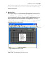
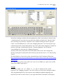
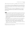
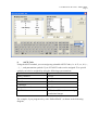
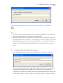
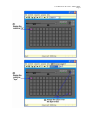
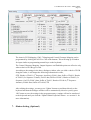
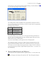
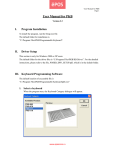
User Manual for EC-C202 - Matrix Maker
Page 1
User Manual for EC-C202 - Matrix Maker
Version 3.5
I.
Program Installation
To install the program, run the Setup.exe file.
The default folder for installation is
“C:\Program Files\Matrix Maker\Programmable Keyboard”.
II.
PS/2 Keyboard and MSR Card Reader Driver Setup
This section is only for Windows 2000 and Windows XP® users who have PS/2 keyboard or
MSR card reader. The default folder for the driver files is "C:\Program Files\Matrix Maker\KB
Driver". For the detailed instructions, please refer to the file, POSKB_DRV_SETUP.pdf, which
is in the default folder.
III. Keyboard Programming Software
The default location of the executable file is
"C:\Program Files\Matrix Maker\Programmable Keyboard\MatrixMaker.exe"
1. Select a keyboard
When the program runs, the Keyboard Category dialogue will appear.
User Manual for EC-C202 - Matrix Maker
Page 2
Select the category of the keyboard, and the country layout you want to program, and then
press OK button. The following instructions are based on S78A model, but can also be
applied for other models.
2. Edit Key Map
After selecting a model, you will be displayed with the default key layout which has no
data for the programmable keys. You may notice that if you roll your mouse over certain
keys on the layout image they will change to a light grey color. This indicates that the
keys are programmable. Clicking the left mouse button on that programmable key will
display a popup menu with options of assigning functions to that key. There are six
methods to assign a function to the programmable key which will be explained in greater
detail in the following sections. An example of the key map screen and the five
programming functions are shown below.
Key Lock
[Note: Not all models have Key Lock.]
i.
Key Code
In this method, you can assign any scan codes to a key.
User Manual for EC-C202 - Matrix Maker
Page 3
In the above dialogue window, the most popular key codes (scan codes) are shown in the
“virtual keyboard” area, plus a few special codes which are listed in the “Special Codes”
area. Selecting a key from the “keyboard” area or double clicking an item in “Special
Codes” area will add that key’s code to the “Mapping Sequence” list. You may also type
codes directly from a connected keyboard. Up to 256 codes can be mapped to a single key
position. Selecting a combination from the “Common Mapping” list will add the
corresponding key codes into the “Mapping Sequence”.
Any key codes (scan codes) that are not selectable in this screen can be mapped by
directly entering the hexadecimal code for that key into the box next to “0x” and pressing
“Insert”.
For the definition of scan codes, please download Scan Code Translation Table from
http://download.microsoft.com/download/1/6/1/161ba512-40e2-4cc9-843a-923143f3456c
/translate.pdf.
For a PS/2 device, please enter a PS/2 Set 2 code. For a USB device, please enter a HID
Usage ID in HID Usage Page 07.
Example
If you press “Shift”, “H”, “E”, “Shift”, “L”, “L”, and “O” buttons in the “virtual
keyboard”, the “Mapping Sequence” list will be shown as in the above dialogue window.
After programming this key code sequence and sending the updated mapping to the
keyboard (covered in a later section), if you type this button in Notepad, it will display
User Manual for EC-C202 - Matrix Maker
Page 4
“HEllo” if the Caps Lock is off. However, it will display “heLLO” if the Caps Lock is on.
If you want to delete “O” in the above “Mapping Sequence” list, you can right click the
“O” item. A popup menu with two options will appear. Selecting the “Delete” option will
delete the “O” item. Selecting the “Clear All” will remove all the items in the “Mapping
Sequence” list.
If you want to add “S” before “H” in the above “Mapping Sequence” list, click the “H”
item in the list first, then press “S” in the “virtual keyboard” picture. If you want to
append the codes at the end of the list, please make sure to select an empty mapping
position in the list.
Caution:
1. Please pay special attention when using the Shift, Alt, and Ctrl keys as they have two
states: down and up. For example, if you press the left Shift key once in the “virtual
keyboard” area, you will only get a down code which will keep the key in a down
state. If you were to keep this programming and press that key in an application, it
would behave as if the left Shift key was down continuously. Again please pay special
attention to the function of these keys and their respective up/down codes to get the
functions you desire.
2. For PS2 interface, if <Pause> code is assigned, no other codes can be appended. On
the other hand, if other code is assigned, the <Pause> code cannot be appended.
3. For USB interface, the following codes cannot be assigned with other codes:
<Wake>, <Sleep>, <Power>, <Vol Up>, <Vol Down>, <Media Select>, <Mail>,
<Calculator>, <My Computer>, <WWW Search>. On the other hand, if other code is
assigned, the above codes cannot be appended.
Depending on the version of the software, you can change the virtual keyboard layout by
selecting the country you like as shown below.
User Manual for EC-C202 - Matrix Maker
Page 5
ii.
ASCII Code
Using the ASCII method, you can assign any printable ASCII Codes, i.e. A-Z, a-z, 0-9, +,
- ,* , / , and punctuation symbols. Up to 255 ASCII codes can be assigned. Five special
symbols can also be assigned by using the following representations:
Symbol
Representation
Enter Character
\n or \N
Esc Character
\e or \E
Tab Character
\t or \T
\ Character
\\
Delay 0.5 second
\d or \D
ASCII Code
\xHH where HH must be a two-digit
hexadecimal integer
For example, if you program a key with “Hello\nWorld”, as shown in the following
diagram,
User Manual for EC-C202 - Matrix Maker
Page 6
After programming this button, if you type this button in Notepad, it will display,
Hello
World
Note:
1. Caps Lock will not modify the output of keys using this method. The key codes will
always be output in the same way they are programmed in.
2. The output of the character string follows the Country Code setting in the Keyboard
Setting dialogue (Refer to Section 3). For example, if you enter “How are you?” from
the keyboard connected to your PC with a German OS, but you choose USA for the
Country Code in the Keyboard Setting dialogue, the output will become “How are
zou?”.
iii.
Customize Code (For PS/2 keyboard only)
This method allows a user to directly assign PS/2 Set 2 Scan Codes for the key.
The codes entered in the “Make Code” field will be sent if the key is pressed down
while the codes entered in the “Break Code” field will be sent when the key is
pressed up. For example, the codes in the above diagram are the Scan Codes for left
shift’s make code(12), h’s make code(33), h’s break code(f0 33), left shift’s break
User Manual for EC-C202 - Matrix Maker
Page 7
code(f0 12), e’s make code(24), e’s break code(f0 24), l’s make code(4b), l’s break
code(f0 4b), o’s make code(44) and o’s break code(f0 44).
Note:
1. Please enter the codes in hexadecimal format and use space to separate the
codes.
2. Each code should have at most 2 characters (0-9, A-F or a-f).
3. Please do not use codes 00 or 02 as they are reserved by the program.
iv.
Layer Index
Layers are useful in programming different codes to the same key. The output of the
codes will be determined by the layer index which can be selected by another key
programmed with the appropriate layer index code. There are at most 16 different
programmable layers depending on the category of the keyboard. You can assign a layer
index to any programmable key you like. Below is a screenshot of the Layer Index popup
dialogue. After programming a layer index to a key, this key will be reserved on all layers.
Layer index keys can be regarded as performing a function much like the Shift key: when
pressed and held down, it will output a different code than the base layer would normally
send. For example if a key is programmed to output “hi” on layer 0 and “bye” on layer 1,
it will output “hi” when pressed normally and “bye” when pressed while holding the key
assigned to perform the “Layer 1 index” function (please see the following screenshots
for further explanation).
User Manual for EC-C202 - Matrix Maker
Page 8
User Manual for EC-C202 - Matrix Maker
Page 9
After programming this key map, if you press the X button in the keyboard, it will display
“hi”. If you change the key lock to the position OP (or pressing the Y button without
releasing), it will display “bye” if you press the X button.
To program key codes on alternate layers, please select each layer from the drop down
menu located on the toolbar (shown in the below screenshot) and program key codes as
explained in the previous sections. Please keep in mind that you must assign a
corresponding layer index key to output layer-based codes. You may also assign layer
indexes to the key lock if available (optional).
v.
OPOS Code (Optional)
Any keys can be assigned to an OPOS key which is handled by our OPOS driver.
Our OPOS driver is designed to support up to 180 OPOS Keys.
Note:
1. Our OPOS driver must be installed first.
vi.
Monitor Menu (Only for the keyboard with a 5.6” monitor display)
Any keys can be assigned to control the monitor. The available options are as shown
User Manual for EC-C202 - Matrix Maker
Page 10
below.
1.
2.
3.
Menu Button – Display a menu in the monitor
Up Button – Move the cursor up in the menu
Down Button – Move the cursor down in the menu.
4.
5.
6.
Left Button – Move the cursor to the left in the menu.
Right Button – Move the cursor to the right in the menu.
Power – To turn on/off the monitor.
Note:
The programmable keys assigned as these codes are effective only when the keyboard
connected to the PC which is powered on.
3. Keyboard Setting
(This setting will not be provided if a RS232 magnetic card reader is selected in the
Keyboard Category dialogue. If a PS2 or USB magnetic card reader is selected, only
“Country Code” setting is meaningful.)
On the menu bar, click ‘Keyboard’ and then ‘Keyboard Setting’, the following dialogue
window will appear,
Note:
User Manual for EC-C202 - Matrix Maker
Page 11
The button “MSR Track 1 Mapping” is invisible for all PS2 and RS232 devices.
To make the keyboard beep upon pressing a key, please check the ‘Beep Enable’ box. You
may then select if you would like all keys to beep or only programmed keys to beep when
pressed down.
If you would like the key codes to be output repeatedly when pressing the button
continuously, click ‘Repeat Enable’ option. If this is not selected the code associated with
each key will only be output once even while holding down a key. [Caution:
If you choose ‘Repeat Enable’ option and you assign non layer index for certain key lock
position, for example, assigning “Hello” for key lock L. When the key is switched on L
position, “Hello” will be generated repeatedly. If you choose ‘Beep Enable’ at the same
time, you will hear a continuous beep sound. Therefore, it is recommended the key lock
be assigned a layer index.]
Depending on what type of keyboard chosen, you can assign a country code in the
keyboard setting. This country code will affect what the MSR card reader (if available)
and the keys programmed by the ASCII code method.
For a USB device with MSR function, you can change the default mapping for MSR
Track 1 Data by pressing the button “MSR Track 1 Mapping”.
Note:
To display the mapping correctly on your PC, you should choose the Country Code in the
User Manual for EC-C202 - Matrix Maker
Page 12
Keyboard Setting dialogue window compatible with your OS language.
After editing the settings, you may press ‘Update’ button to send them directly to the
keyboard and then the dialogue window will be automatically closed or you my press
‘OK’ button to save the settings in the program memory (settings will not be transferred
to the keyboard until you click the ‘Update Whole Keyboard’ button – see section 11 for
more information).
4. Magstripe Card Reader Setting (Optional)
On the menu bar, click ‘Keyboard’ and then ‘Magstripe Card Reader Setting’, or on the
toolbar, click
icon. The following dialogue window will appear,
The header, separator, and suffix can be programmed by clicking the ASCII or Code radio
buttons. This will bring up a window for input similar to programming normal keys on the
keyboard.
Options
The following settings are not supported by all devices. Please contact us for more
information if you find that your device does not support these settings.
1. Detect IBM card
Some IBM cards have special formats. If you want to read the card correctly, you
User Manual for EC-C202 - Matrix Maker
Page 13
2.
3.
4.
5.
6.
7.
may try to select this option.
Support OPOS
It can be used in any system installed with OPOS driver for MSR.
Reverse reading
The track data will be read from right to left, instead of from left to right. It is
suitable for some languages, e.g. Hebrew.
Output data for any valid track
If there is an invalid track in the card, it still can display the remaining valid tracks.
Output credit card A/C No.
It can display the credit card A/C No. only for track 2.
Enable LRC
It can display the LRC after then end sentinel for each track.
Shown in digital format
If it is checked, the LRC will be displayed in the 2-byte digital format. If it is
unchecked, the LRC will be displayed in the character format. For example, if the
LRC in Track 1 is 0x31, it will display “31” when it is checked and it will display
“Q” when it is unchecked.
Note:
1. The code length for Header, Separator, and Suffix are limited to 16 only.
2. For all RS232 devices, you can only enter 1 character for each sentinel. If you enter
more than 1 character, the software will discard all characters.
3. For some PS/2 and USB devices, you can enter not more than 16 characters for each
sentinel. You can use \n to represent the new line character in each sentinel.
4. For a RS232 device, they can only be programmed by using ASCII method.
According to the settings in the above dialogue window, after you slide a magstripe card
along the reader, it will output the following information in order,
Header codes, Track 1 Start Sentinel, Track 1 Data, Track 1 End Sentinel, Separator codes,
Track 2 Start Sentinel, Track 2 Data, Track 2 End Sentinel, Separator codes, Track 3 Start
Sentinel, Track 3 Data, Track 3 End Sentinel, Suffix codes.
After editing the settings, you may press ‘Update’ button to send them directly to the
keyboard and then the dialogue window will be automatically closed or you my press
‘OK’ button to save the settings in the program memory (settings will not be transferred
to the keyboard until you click the ‘Update Whole Keyboard’ button – see section 11 for
more information).
User Manual for EC-C202 - Matrix Maker
Page 14
5. Bar Code Reader Setting (Optional)
On the menu bar, click ‘Keyboard’ and then ‘Bar Code Reader Setting’, or on the toolbar,
icon. The following dialogue window will appear,
click
The header and suffix can be programmed by clicking the ASCII or Code radio buttons.
This will bring up a window for input similar to programming normal keys on the
keyboard.
After editing the settings, you may press ‘Update’ button to send them directly to the
keyboard and then the dialogue window will be automatically closed or you my press
‘OK’ button to save the settings in the program memory (settings will not be transferred
to the keyboard until you click the ‘Update Whole Keyboard’ button – see section 11 for
more information).
6. MICR Setting (Optional)
On the menu bar, click ‘Keyboard’ and then ‘MICR Setting’, or on the toolbar, click
icon. The following dialogue window will appear,
User Manual for EC-C202 - Matrix Maker
Page 15
The items in E13B Mapping, CMC-7 Mapping and Control Character Mapping can be
programmed by clicking the ASCII or Code radio buttons. This will bring up a window
for input similar to programming normal keys on the keyboard.
The Control Character Mapping, Output Sequence and Enabled options are effective only
when a check of E13B type is read.
According to the settings in the above dialogue window, after you slide a check of E13B
along the reader, it will output the following information in order,
STX, Header of Field 1 (1st Sequence: Auxiliary), Field 1 data, Suffix of Field 1, Header
of Field 2 (2nd Sequence: Transit), Field 2 data, Suffix of Field 2, Header of Field 3 (3rd
Sequence: On-US), Field 3 data, Suffix of Field 3, Header of Field 4 (4th Sequence:
Amount), Field 4 data, Suffix of Field 4, ETX
After editing the settings, you may press ‘Update’ button to send them directly to the
keyboard and then the dialogue window will be automatically closed or you my press
‘OK’ button to save the settings in the program memory (settings will not be transferred
to the keyboard until you click the ‘Update Whole Keyboard’ button – see section 11 for
more information).
7. iButton Setting (Optional)
User Manual for EC-C202 - Matrix Maker
Page 16
On the menu bar, click ‘Keyboard’ and then ‘iButton Setting’, or on the toolbar, click
icon. The following dialogue window will appear,
The Leading, Header, Suffix and Ending can be programmed by clicking the ASCII or
Scan Code radio buttons. This will bring up a window for input similar to programming
normal keys on the keyboard.
The default settings for these 4 keys are:
Symbol
Values
Header
<Empty>
Suffix
Enter (Scan Code)
Leading
~~~~~~ (ASCII)
Ending
~~~~~~ (ASCII)
If you put the iButton on top of the sensor, it will output the following information in
order, the values of Leading Symbol, the values of Header Symbol, Data stored on the
iButton and the values of Suffix Symbol.
If you move out the iButton, it will output the values of Ending Symbol.
After editing the settings, you may press ‘Update’ button to send them directly to the
keyboard and then the dialogue window will be automatically closed or you my press
‘OK’ button to save the settings in the program memory (settings will not be transferred
to the keyboard until you click the ‘Update Whole Keyboard’ button – see section 11 for
more information).
8. Firmware Update (Except for the USB device)
On the menu bar, click ‘Keyboard’ and then ‘Update Firmware’, or on the toolbar, click
icon. Navigate to the firmware file and click “OK”. This will begin the firmware
User Manual for EC-C202 - Matrix Maker
Page 17
update.
During updating, please do not press any keys on the keyboard or click the mouse for
better performance.
9. Diagnostic
i.
Enter Test Mode
Pressing a key will show that key’s position. (For testing the keyboard only.) If
your keyboard has key lock feature and the repeat feature is turned on, the
keyboard will continuously send the key lock position. To stop this, you can press
any other key.
ii.
Exit Test Mode
Pressing a key will show the code programmed to that key.
iii.
Load Factory Setting
Reload the default factory setting to the device. This function can be used when
the QUERTY section of the keymap is lost. For the USB keyboard, please re-plug
the keyboard and close the software after executing this function successfully.
iv.
Reset
Reset the keyboard only. (For testing the keyboard only.)
v.
Ignore the middle device (For PS/2 device)
In case two of our PS/2 devices are connected by loop-through, you can directly
program the device which is connected to the PS/2 port of your PC. But if you
want to program the 2nd device, you need to ignore the middle device (i.e. the one
which is connected to the PS/2 port of your PC) first.
Note: Once the middle device is ignored, it will be disabled.
vi.
Restore the middle device (For PS/2 device)
To enable the middle device, you need to restore it first.
vii.
Firmware Version
Get the current version of the firmware.
viii.
MCU Type (Disabled)
Get the type of the MCU being used by the device.
10. Update Key Mappings
To send only the key mapping data to the keyboard device, click Keyboard > Update Key
Mappings on the menu bar or on the toolbar, click
icon.
User Manual for EC-C202 - Matrix Maker
Page 18
During updating, please do not press any keys on the keyboard or click the mouse for
better performance.
11. Update Whole Keyboard
To send the settings for the entire keyboard device (including MSR settings, Keyboard
Settings, key mapping data, Barcode Settings, MICR Settings and iButton Settings), click
Keyboard > Update Whole Keyboard on the menu bar.
During updating, please do not press any keys on the keyboard or click the mouse for
better performance.
12. Retrieve Keyboard
To retrieve the data currently programmed to a keyboard device (including MSR settings,
Keyboard Settings, key mapping data, Barcode Settings, MICR Settings and iButton
Settings), click Keyboard > Retrieve Keyboard on the menu bar or click
icon on the
toolbar.
During retrieving, please do not press any keys on the keyboard for better performance.
13. Clear All
To clear the data in the Matrix Maker program memory (including MSR settings,
Keyboard Settings, and key mapping data), click Keyboard > Clear All on the menu bar
or click
icon on the toolbar. This action only clears the Matrix Maker program
memory - it does not clear the settings in the actual keyboard.
14. Save
To save all current settings in the Matrix Maker program memory to a file, click File >
Save on the menu bar or click
icon on the toolbar.
User Manual for EC-C202 - Matrix Maker
Page 19
15. Open
To open a saved Matrix Maker settings file, click File > Open on the menu or click
icon on the toolbar. An error may occur if you choose a setting file of a newer version on
the Matrix Maker software with an older version.
16. Default Keymap
You can set the default key mappings for each model in the Matrix Maker by clicking File
> Set Default on the menu bar. Once a key mapping is set as default, it will be
automatically lo aded the next time this model is selected.
IV. Batch Update
You can update the keymap or the firmware automatically by creating a batch file. After
updating, the program will be closed automatically.
1.
Keymap Update
The format of the batch file for updating keymap for a PS2 or USB device,
"Location_of_Executable_File" -1"Location_of_Keymap_File" -t"Category"
For example,
"C:\Program Files\Matrix Maker\Programmable Keyboard\MatrixMaker.exe"
-1"C:\temp\s78a.dat" -t"S78A"
The format of the batch file for updating keymap for a RS232 device,
"Location_of_Executable_File" -1"Location_of_Keymap_File" -t"Category"
-s"Port,Baud"
For example,
"C:\Program Files\Matrix Maker\Programmable Keyboard\MatrixMaker.exe"
-1"C:\temp\C202AC.dat" -t"C202AC" -s"1,57600"
2.
Firmware Update (Except for the USB device)
The format of the batch file for updating firmware for a PS2 device,
"Location_of_Executable_File" -2"Location_of_Firmware_File" -t"Category"
For example,
"C:\Program Files\Matrix Maker\Programmable Keyboard\MatrixMaker.exe"
User Manual for EC-C202 - Matrix Maker
Page 20
-2"C:\temp\poskb.bin" -t"S78A"
The format of the batch file for updating firmware for a RS232 device,
"Location_of_Executable_File" -2"Location_of_Firmware_File" -t"Category"
-s"Port,Baud"
For example,
"C:\Program Files\Matrix Maker\Programmable Keyboard\MatrixMaker.exe"
-2"C:\temp\poskb.bin" -t"C202AC" -s"1,57600"
Note:
a. There is a space before -1, -2, -t, and -s but no space after -1, -2, -t and -s.
b.
The double quotation mark is required.
www.ecline.com.mx