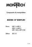
1
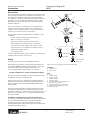
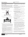
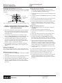
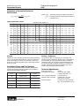
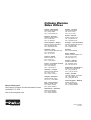
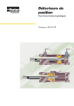
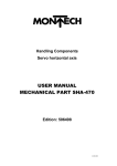
Bulletin HY07-1244 -T1/UK
Hydraulics
Operating Instructions
UCA Charging
& Gauging Kit
Effective:
01 July 2001
For use with Piston,
Bladder & Diaphragm
Accumulators
Bulletin HY07-1244-T1/UK
Charging & Gauging Kit
UCA
Warning
FAILURE OR IMPROPER SELECTION OR IMPROPER USE OF THE PRODUCTS AND/OR SYSTEMS DESCRIBED HEREIN
OR RELATED ITEMS CAN CAUSE DEATH, PERSONAL INJURY AND PROPERTY DAMAGE.
This document and other information from Parker Hannifin Corporation, its subsidiaries and authorized distributors provide
product and/or system options for further investigation by users having technical expertise. It is important that all aspects of
the application are analysed and the information concerning the product or system in the current product catalogue is
reviewed. Due to the variety of operating conditions and applications for these products or systems, the user, through its
own analysis and testing, is solely responsible for making the final selection of the products and systems and assuring that
all performance, safety and warning requirements of the application are met.
The products described herein, including without limitation, product features, specifications, designs, availability and
pricing, are subject to change by Parker Hannifin Corporation and its subsidiaries at any time without notice.
2
Hydraulics
Parker Hannifin plc
Cylinder Division
Watford, Herts.
Bulletin HY07-1244 -T1/UK
Introduction
Charging & Gauging Kit
UCA
Description
B
The UCA universal charging & gauging kit is required to check
the precharge pressure of an accumulator and to fill and vent
the nitrogen. It is suitable for all Parker piston and bladder
accumulators, and other commercially available accumulators
with M28 x 1.5, 7/8-14 UNF, 5/8-18 UNF or 0.305-32 UNS
(8V1-Vg 8) gas valves, operating up to a maximum working
pressure of 340 bar.
6
10
5
8
The UCA assembly is screwed onto the accumulator’s gas
valve and connected to the nitrogen source with the hose
supplied. If the precharge pressure is only to be checked or
reduced, the connection hose is not required.
A
1
The standard charging and gauging kit is supplied in a case
containing:
7
9
– a 'UCA' universal charging & gauging kit with
M28 x 1.5 gas port connection
M28 x 1.5
– two pressure gauges, 0-25 bar and 0-250 bar *
– three adapters for connection to the accumulator
gas valve (7/8 -14 UNF; 5/8 -18 UNF; 0.305-32 UNS)
2
– a 2.5m long hose, for connection to a nitrogen source
3
– a 6mm A/F hexagon wrench
– a set of spare seals
5/8- 18 UNF
* where a different pressure range is required, a commerciallyavailable pressure gauge may be used.
7/8 -14 UNF
Safety
4
0.305 - 32 UNS
(8V1-Vg 8)
Charging must be carried out by qualified personnel.
Figure 1 Universal Charging and Gauging Kit assembly
Before taking any readings or pressurizing with nitrogen, the
accumulator must be isolated from the hydraulic system and
the fluid side discharged in order to depressurize it.
Use only nitrogen (N2) to pressurize the accumulator.
Controls
A
B
Danger of Explosion – Never Charge with Oxygen
Inflation valve
Bleed valve
Key
1
2
3
4
5
6
7
8
9
10
The types of nitrogen permitted are: type S (99.8% pure); type
R (99.99% pure); type U (99.993% pure).
If the pressure of the gas contained in the nitrogen bottle is
greater than the maximum permissible operating pressure of
the accumulator, a pressure regulator must be fitted to the
nitrogen bottle.
UCA
Adapter (long)
Adapter (short)
Adapter (insert)
Pressure gauge
Knurled protective cap – gauge port
Knurled collar – gas port
Knurled protective cap – filling port
Filling hose (G1/4 fitting, 60° cone)
Filling port valve
Parker recommends that the precharge should be checked
during the first week following commissioning of the system.
Thereafter, it should be checked after three months and then at
intervals of 12 months or less, as considered appropriate by
the system builder.
The Effect of Temperature on Precharge Pressure
In order to compensate for the difference in pressure at ambient
and operating temperatures, it is recommended that the
precharge pressure po should be adjusted to reflect the
operating temperature of the system, using the correction factor
equations and table on page 7.
3
Hydraulics
Parker Hannifin plc
Cylinder Division
Watford, Herts.
Charging & Gauging Kit
UCA
Bulletin HY07-1244-T1/UK
Pressure Adjustment
To Check and Adjust the Precharge Pressure
6
Warning – Stabilization
The process of charging or discharging an accumulator with
nitrogen causes a temperature change which is transmitted to
the surrounding air as the temperature of the accumulator
stabilizes. To allow for the effects of temperature transfer, the
accumulator should be allowed to stand for a minimum of 15
minutes before a final reading of the precharge pressure is taken.
Open the inflation valve (A) by screwing the handwheel
clockwise until the inflation pressure registers on the gauge.
Readings and Results
One of three conditions will apply – the precharge pressure in
the accumulator will be correct, or it will be too high or too low.
Nitrogen Pressure po is Correct
1 Screw the handwheel (A) anti-clockwise to close the
accumulator gas valve.
Bladder or Piston Accumulators with
Schrader-type Valve Figures 1, 2a & 2b
Outer cap 11
2
Slacken the bleed valve (B) to release pressure in the UCA.
3
Unscrew the UCA from the adapter.
4
Unscrew the adapter(s) from the accumulator gas valve.
Nitrogen Pressure po is Too High
1 Slacken the bleed valve (B) to vent nitrogen from the
accumulator until, after stabilization, the desired pressure
po is registered. Nitrogen vents into the air.
Gas valve 13
Inner cap12
Figure 2a Bladder accumulator with Schrader-type gas valve
Protective cover 14
2
Tighten the bleed valve (B) once the desired filling pressure
is reached.
3
Screw the handwheel (A) anti-clockwise to close the
accumulator gas valve.
4
Slacken the bleed valve (B) to release pressure in the UCA.
5
Unscrew the UCA from the adapter.
6
Unscrew the adapter(s) from the accumulator gas valve.
Gas valve cap 15
Nitrogen Pressure po is Too Low
1 Close the inflation valve (A) by screwing the handwheel
anti-clockwise..
Gas valve 16
2
Remove the knurled cap on the filling port (8).
3
Connect the end of the filling hose (9) to the filling port
valve (10).
4
Connect the other end of the hose to the nitrogen source.
5
Progressively open the valve on the nitrogen source.
6
Screw the handwheel (A) clockwise to admit the pressurized gas, taking particular care if the accumulator has a
small capacity or is of the low pressure type ( < 40 bar).
7
When pressure po is reached, close the valve on the
nitrogen source. To allow for the effects of temperature
transfer, the accumulator should be allowed to stand for a
minimum of 15 minutes to allow the temperature to stabilize
before a final reading of the precharge pressure is taken.
8
Screw the handwheel (A) anti-clockwise to close the
accumulator gas valve.
9
Slacken the bleed valve (B) to release pressure in the UCA.
Figure 2b Piston accumulator with Schrader-type gas valve
1
Unscrew the caps (11 and 12) from a bladder accumulator
or the protective cover and cap (14 and 15) from a piston
accumulator, to gain access to the gas valve (13 or 16).
2
Select the appropriate pressure gauge (5) for the pressure
to be checked, remove the protective cap (6) and attach
the gauge to the UCA (1).
3
4
5
Make sure that the bleed valve (B) is fully closed and that
the inflation valve (A) is in the fully raised position by
turning the handwheel in an anti-clockwise direction.
10 Remove the hose carefully, to release internal pressure.
Bladder accumulators: Ensure that the o-ring is correctly
positioned in the base of the long adapter (2), screw the
adapter on to the gas valve (13) and hand tighten.
Piston accumulators: Assemble the short adapter and
adapter insert (3 and 4), screw onto the gas valve (16) and
hand tighten.
11 Refit the knurled cap (8) to the filling port valve (10).
12 Unscrew the UCA from the adapter(s).
13 Unscrew the adapter(s) from the accumulator gas valve.
After removing the UCA and adapter(s), make sure that the
accumulator gas valve (13 or 16) is sealing effectively. Refit the
protective cap(s) (11, 12, 15) and cover (14), where applicable.
Screw the UCA onto the adapter. Position the assembly to
permit easy reading of the gauge, then hand tighten the
knurled collar (7).
4
Hydraulics
Parker Hannifin plc
Cylinder Division
Watford, Herts.
Charging & Gauging Kit
UCA
Bulletin HY07-1244 -T1/UK
Pressure Adjustment
Piston Accumulators with
Poppet-type Valve Figures 1 & 3
Nitrogen Pressure po is Too High
1 Slacken the bleed valve (B) to vent nitrogen from the
accumulator until, after stabilization, the desired pressure
po is registered. Nitrogen vents into the air.
1
Unscrew the protective cover (17), where fitted, and cap
(18) from the accumulator gas valve (19).
2
Assemble the short adapter and adapter insert (3 and 4),
and screw onto the accumulator gas valve.
2
Tighten the bleed valve (B) once the desired filling pressure
is reached.
3
Select the appropriate pressure gauge (5) for the pressure
to be checked, remove the protective cap (6) and attach
the gauge to the UCA (1). Make sure that the bleed valve
(B) is fully closed. The position of inflation valve (A) can be
ignored, as it does not affect this procedure.
3
Close the accumulator gas valve by screwing the adjuster
nut (20) clockwise..
4
Screw the UCA onto the adapter. Position the assembly to
permit easy reading of the gauge, then hand tighten the
knurled collar (7).
5
Open the accumulator gas valve by turning the hexagonal
poppet valve adjuster nut (20) anti-clockwise until the
inflation pressure registers on the gauge.
4
Slacken the bleed valve (B) to release pressure in the UCA.
5
Unscrew the UCA from the adapter.
6
Unscrew the adapter (3) and adapter insert (4) from the
accumulator gas valve (19).
Nitrogen Pressure po is Too Low
1 Close the accumulator gas valve by screwing the poppet
valve adjuster nut (20) clockwise..
Note: for 360mm bore accumulators, a 19mm A/F spanner
approximately 120mm long should be used to turn the
valve adjuster nut (20).
Protective cover 17
Protective cap 18
2
Remove the knurled cap on the filling port (8).
3
Connect the end of the filling hose (9) to the filling port
valve (10).
4
Connect the other end of the hose to the nitrogen source.
5
Progressively open the valve on the nitrogen source.
6
Open the accumulator gas valve by screwing the adjuster
nut (20) anti-clockwise, to admit the pressurized gas,
taking particular care if the accumulator has a small
capacity or is of the low pressure type ( < 40 bar).
7
When pressure po is reached, close the valve on the
nitrogen source. To allow for the effects of temperature
transfer, the accumulator should be allowed to stand for a
minimum of 15 minutes to allow the temperature to stabilize
before a final reading of the precharge pressure is taken.
8
Close the accumulator gas valve by screwing the adjuster
nut (20) clockwise..
9
Slacken the bleed valve (B) to release pressure in the UCA.
Gas valve 19
Adjuster nut 20
10 Remove the hose (9) carefully, to release internal pressure.
Figure 3 Poppet-type accumulator gas valve
11 Refit the knurled cap (8) to the filling port valve (10).
Readings and Results
One of three conditions will apply – the precharge pressure in
the accumulator will be correct, or it will be too high or too low.
12 Unscrew the UCA from the adapter.
13 Unscrew the adapter (3) and adapter insert (4) from the
accumulator gas valve (19).
Nitrogen Pressure po is Correct
1 Close the accumulator gas valve by turning the poppet
valve adjuster nut (20) clockwise.
2
Slacken the bleed valve (B) to release pressure in the UCA.
3
Unscrew the UCA from the adapter.
4
Unscrew the adapter (3) and adapter insert (4) from the
accumulator gas valve (19).
After removing the UCA and adapters, make sure that the
accumulator gas valve is sealing effectively. Refit the protective cap
(18) and protective cover (17) to the accumulator gas valve (19).
5
Hydraulics
Parker Hannifin plc
Cylinder Division
Watford, Herts.
Charging & Gauging Kit
UCA
Bulletin HY07-1244-T1/UK
Pressure Adjustment
Diaphragm Accumulators Figures 1 & 4
Nitrogen Pressure po is Too High
1 Slacken the bleed valve (B) to vent nitrogen from the
accumulator until, after stabilization, the desired pressure
po is registered. Nitrogen vents into the air.
The following instructions apply only to diaphragm accumulators
fitted with a socket-headed screw type gas valve, as illustrated
in Figure 4.
2
Tighten the bleed valve (B) once the desired filling pressure
is reached.
3
Screw the handwheel (A) clockwise to close the accumulator
gas valve.
4
Slacken the bleed valve (B) to release pressure in the UCA.
5
Unscrew the UCA from the accumulator gas valve.
6
Using the 6mm hexagon wrench supplied, ensure that the
hexagon socket-headed gas valve screw (22) is firmly
tightened. Refit the protective cap (21) to the accumulator
gas valve.
Cap 21
Gas valve
socket-headed
screw 22
Figure 4 Diaphragm accumulator with socket-headed screw gas valve
Danger – do not attempt to loosen the gas valve
screw with a hexagon wrench, as it could be ejected
under extreme pressure
Nitrogen Pressure po is Too Low
1 Close the inflation valve (A) by screwing the handwheel
clockwise.
2
Remove the knurled cap (8) on the filling port.
3
Connect the end of the filling hose (9) to the filling port
valve (10).
4
Connect the other end of the hose to the nitrogen source.
5
Progressively open the valve on the nitrogen source.
6
Screw the handwheel (A) anti-clockwise to admit the
pressurized gas, taking particular care if the accumulator
has a small capacity or is of the low pressure type (< 40 bar).
7
When pressure po is reached, close the valve on the
nitrogen source. To allow for the effects of temperature
transfer, the accumulator should be allowed to stand for a
minimum of 15 minutes to allow the temperature to stabilize
before a final reading of the precharge pressure is taken.
8
Screw the handwheel (A) clockwise to close the accumulator gas valve.
One of three conditions will apply – the precharge pressure in
the accumulator will be correct, or it will be too high or too low.
9
Slacken the bleed valve (B) to release pressure in the UCA.
Nitrogen Pressure po is Correct
1 Screw the handwheel (A) clockwise to close the accumulator
gas valve.
11 Refit the knurled cap (8) to the filling port valve (10).
1
Select the appropriate pressure gauge (5) for the pressure
to be checked, remove the protective cap (6) and attach
the gauge to the UCA (1). Make sure that the bleed valve
(B) is fully closed.
2
Unscrew the cap (21) from the accumulator gas valve.
Release, but do not loosen, the socket-headed gas valve
screw (22) using the 6mm hexagon wrench supplied.
3
4
Screw the knurled collar (7) on the base of the UCA (1)
onto the accumulator gas valve. Ensure that the male
hexagon in the base of the UCA engages with the female
hexagon in the accumulator gas valve (22).
Open the inflation valve (A) by screwing the handwheel
anti-clockwise until the inflation pressure registers on the
gauge.
Readings and Results
2
Slacken the bleed valve (B) to release pressure in the UCA.
3
Unscrew the UCA from the accumulator gas valve.
4
Using the 6mm hexagon wrench supplied, ensure that the
hexagon socket-headed gas valve screw (22) is firmly
tightened. Refit the protective cap (21) to the accumulator
gas valve.
10 Remove the hose carefully, to release internal pressure.
12 Unscrew the UCA from the accumulator gas valve.
13 Using the 6mm hexagon wrench supplied, ensure that the
hexagon socket-headed gas valve screw (22) is firmly
tightened. Refit the protective cap (21) to the accumulator
gas valve.
6
Hydraulics
Parker Hannifin plc
Cylinder Division
Watford, Herts.
Charging & Gauging Kit
UCA
Bulletin HY07-1244-T1/UK
Correction Factors
Calculation of Correction Factors at
Full Pressure
where: p0 (t2) = precharge pressure at working temperature t2
p0 (t0) = precharge pressure at precharge temperature t0
t + 273
p0 (t 0 ) = p0 (t 2 ) 0
= p0 (t 2 ) × K
t 2 + 273
Operating Temperature t2 °C
Table of Correction Factors
K
= correction factor
Precharge Temperature t0 °C
-20
-10
0
5
10
15
20
25
30
35
40
50
60
70
80
90
100
-20
1.00
1.04
1.08
1.10
1.12
1.14
1.16
1.18
1.20
1.22
1.24
1.28
1.32
1.36
1.40
1.43
1.47
-10
0.96
1.00
1.04
1.06
1.08
1.10
1.11
1.13
1.15
1.17
1.19
1.23
1.27
1.30
1.34
1.38
1.42
0
0.93
0.96
1.00
1.02
1.04
1.05
1.07
1.09
1.11
1.13
1.15
1.18
1.22
1.26
1.29
1.33
1.37
10
0.89
0.93
0.96
0.98
1.00
1.02
1.04
1.05
1.07
1.09
1.11
1.14
1.18
1.21
1.25
1.28
1.32
20
0.86
0.90
0.93
0.95
0.97
0.98
1.00
1.02
1.03
1.05
1.07
1.10
1.14
1.17
1.20
1.24
1.27
30
0.84
0.87
0.90
0.92
0.93
0.95
0.97
0.98
1.00
1.02
1.03
1.07
1.10
1.13
1.16
1.20
1.23
40
0.81
0.84
0.87
0.89
0.90
0.92
0.94
0.95
0.97
0.98
1.00
1.03
1.06
1.10
1.13
1.16
1.19
50
0.78
0.81
0.85
0.86
0.88
0.89
0.91
0.92
0.94
0.95
0.97
1.00
1.03
1.06
1.09
1.12
1.15
60
0.76
0.79
0.82
0.83
0.85
0.86
0.88
0.89
0.91
0.92
0.94
0.97
1.00
1.03
1.06
1.09
1.12
70
0.74
0.77
0.80
0.81
0.83
0.84
0.85
0.87
0.88
0.90
0.91
0.94
0.97
1.00
1.03
1.06
1.09
80
0.72
0.75
0.77
0.79
0.80
0.82
0.83
0.84
0.86
0.87
0.89
0.92
0.94
0.97
1.00
1.03
1.06
90
0.70
0.72
0.75
0.77
0.78
0.79
0.81
0.82
0.83
0.85
0.86
0.89
0.92
0.94
0.97
1.00
1.03
100
0.68
0.71
0.73
0.75
0.76
0.77
0.79
0.80
0.81
0.83
0.84
0.87
0.89
0.92
0.95
0.97
1.00
110
0.66
0.69
0.71
0.73
0.74
0.75
0.77
0.78
0.79
0.80
0.82
0.84
0.87
0.90
0.92
0.95
0.97
120
0.64
0.67
0.69
0.71
0.72
0.73
0.75
0.76
0.77
0.78
0.80
0.82
0.85
0.87
0.90
0.92
0.95
Example
Warning – Stabilization
Satisfactory system operation requires a precharge pressure of
100 bar. The operating temperature t2 is 50°C and the temperature at precharging t0 is 20°C. From the table, a correction
factor of 0.91 should be applied, giving a precharge pressure
at 20°C of 91 bar.
The process of filling or discharging an accumulator with
nitrogen causes a temperature change which is transmitted to
the surrounding air as the temperature of the accumulator
stabilizes. To allow for the effects of temperature transfer, the
accumulator should be allowed to stand for a minimum of 15
minutes to allow the temperature to stabilize before a final
reading of the precharge pressure is taken.
Gas Bottle Fittings and Part Numbers
To meet the requirements of different markets, Parker’s UCA
Charging and Gauging Kits are supplied with an adapter to
suit the appropriate gas bottle fitting.
Country
Gas Bottle Fitting
Part No.
UK
5/8 BSP (male)
UCA 02
France
W 21.7 x 1/14" (female)
UCA 04
Germany
W 24.32 x 1/14" (female)
UCA 01
Italy
W 21.7 x 1/14" (male)
UCA 05
US
0,960 x 1/14" (male)
UCA 03
Technical Specification
Maximum pressure
Accumulator connection
UCA – nitrogen bottle hose
Nitrogen bottle connection
Pressure gauges
7
Hydraulics
340 bar
7/8-14 UNF, 5/8-18 UNF,
0.305-32 UNS, M28 x 1.5
2.5m long approx.
5/8" BSP with o-ring seal
(UK: part no. UCA 02)
Two 63mm dia. glycerine-bath
type, 0-25 and 0-250 bar ±1.6%
Parker Hannifin plc
Cylinder Division
Watford, Herts.
Cylinder Division
Sales Offices
Austria – Marchtrenk
Parker Hannifin GmbH
Tel: (7242) 56921
Fax: (7242) 5692120
Norway – Langhus
Parker Hannifin A/S
Tel: 64 91 10 00
Fax: 64 91 10 90
Belgium – Brussels
Parker Hannifin SA NV
Tel: 67 280 900
Fax: 67 280 999
Poland – Warsaw
Parker Hannifin Corp.
Tel: (22) 863 49 42
Fax: (22) 863 49 44
Czech Republic – Prague
Parker Hannifin Corporation
Tel: (02) 830 85 221
Fax: (02) 830 85 360
Portugal – Leca da Palmeira
Parker Hannifin Portugal Lda.
Tel: (22) 999 7360
Fax: (22) 996 1527
Denmark – Ishøj
Parker Hannifin Danmark A/S
Tel: 43 56 04 00
Fax: 43 73 31 07
Slovakia
Ref. Czech Republic
Finland – Vantaa
Parker Hannifin Oy
Tel: 9 476 731
Fax: 9 476 73200
France – Contamine-sur-Arve
Parker Hannifin SA
Tel: 4 50 25.80.25
Fax: 4 50 03.67.37
Germany – Cologne
Parker Hannifin GmbH
Tel: (221) 71720
Fax: (221) 7172219
Hungary – Budapest
Parker Hannifin Corp.
Tel + Fax: 1 252 2539
Need a Parker part?
Call Parker's European Product Information Centre
on 00800 27 27 5374
Visit us at www.parker.com
Hydraulics
Italy – Arsago-Seprio
Parker Hannifin S.p.A.
Tel: (0331) 765611
Fax: (0331) 765612
Spain – Madrid
Parker Hannifin Espana S.A.
Tel: (91) 675 73 00
Fax: (91) 675 77 11
Sweden – Spånga
Parker Hannifin AB.
Tel: 08 5979 50 00
Fax: 08 5979 51 20
Switzerland – Romanshorn
Hydrel A.G. Romanshorn
Tel: (714) 66 66 66
Fax: (714) 66 63 33
Turkey – Istanbul
Hidroser Hidrolik - Pnömatik
Tel: (212) 886 72 70
Fax: (212) 886 69 35
United Kingdom – Watford
Parker Hannifin Plc
Tel: (01923) 492000
Fax: (01923) 248557
Netherlands – Oldenzaal
Parker Hannifin B.V.
Tel: (0541) 585000
Fax: (0541) 585459
1244-T1/UK 2M
CP 0701