1
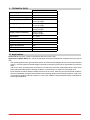
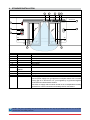
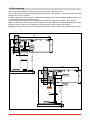
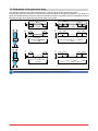
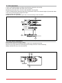
TEN IP1702EN- rev. 2012-01-30 EN Maintenance and Installation Manual for Sliding Doors (Original instructions) DITEC S.p.A. Via Mons. Banfi, 3 - 21042 Caronno Pertusella (VA) - ITALY Tel. +39 02 963911 - Fax +39 02 9650314 www.ditec.it - [email protected] INDEX Subject 1. General safety precautions 2. Declaration of incorporation of partly completed machinery 2.1 Machinery directive 3. Technical data 3.1 Applications 4. Standard installation 5. Installation of the automation 5.1 Housing not joined to the guide 5.2 Box fastening 5.3 Preparation of the door glass wing 5.4 Door wing installation and adjustment 5.5 Floor guide installation 5.6 Housing joined to the guide 5.7 Belt adjustment 5.8 Lock installation 6. Electrical connections 7. Ordinary maintenance program 8. Troubleshooting 8.1 General safety precautions 8.2 Manual release instructions 9. Function selector user instructions Page 3 3 3 4 4 5 6 6 7 8 9 10 10 11 11 12 12 13 13 14 15 CAPTION This symbol indicates instructions or notes regarding safety issues which require particular attention. i This symbol indicates informations which are useful for correct product function. This symbol indicates instructions or notes intended for technical and expert personnel. STOP This symbol indicates operations not to be effected for not compromise the correct operation of the automation. This symbol indicates options and parameters which are only available with the indicated item. This symbol indicates options and parameters which are not available with the indicated item. All right reserved All data and specifications have been drawn up and checked with the greatest care. The manufacturer cannot however take any responsibility for eventual errors, ommisions or incomplete data due to technical or illustrative purposes. IP1702EN • 2012-01-30 2 1. GENERAL SAFETY PRECAUTIONS This installation manual is intended for professionally competent personnel only. Before installing the product, carefully read the instructions. Bad installation could be hazardous. The packaging materials (plastic, polystyrene, etc.) should not be discarded in the environment or left within reach of children, as these are a potential source of hazard. Before installing the product, make sure it is in perfect condition. Do not install the product in an explosive environment and atmosphere: gas or inflammable fumes are a serious hazard risk. Before installing the motors, make all structural changes relating to safety clearances and protection or segregation of all areas where there is risk of being crushed, cut or dragged, and danger areas in general. Make sure the existing structure is up to standard in terms of strength and stability. The motor manufacturer is not responsible for failure to use Good Working Methods in building the frames to be motorised or for any deformation occurring during use. The safety devices (photocells, safety edges, emergency stops, etc.) must be installed taking into account: applicable laws and directives, Good Working Methods, installation premises, system operating logic and the forces developed by the motorised door. Apply hazard area notices required by applicable regulations. Each installation must clearly show the identification details of the motorised door. 2. DECLARATION OF INCORPORATION OF PARTLY COMPLETED MACHINERY (Directive 2006/42/EC, Annex II-B) The manufacturer DITEC S.p.A. with headquarters in Via Mons. Ban, 3 - 21042 Caronno Pertusella (VA) - ITALY Declares that the automation for sliding doors type TEN - Has been constructed to be installed on a manual door to construct a machine pursuant to the directive 2006/42/EC. The manufacturer of the motorised door shall declare conformity pursuant to the directive 2006/42/EC (annex II-A), prior to the machine being put into service. - Conforms to applicable essential safety requirements indicated in annex I, chapter 1 of the directive 2006/42/EC. - Conforms to the Low Voltage Directive 2006/95/EC. - Conforms to the Electromagnetic Compatibility Directive 2004/108/EC. - Technical documentation conforms to annex VII-B to the directive 2006/42/EC. - The technical le is managed by Renato Calza with ofces in Via Mons. Ban, 3 - 21042 Caronno Pertusella (VA) - ITALY. - A copy of technical documentation will be provided to national competent authorities, following a suitably justied request. Caronno Pertusella, Silvano Angaroni 29-12-2009 (Managing Director) 2.1 Machinery directive Pursuant to Machinery Directive (2006/42/EC) the installer who motorises a door or gate has the same obligations as the manufacturer of machinery and as such must: - prepare the technical file which must contain the documents indicated in Annex V of the Machinery Directive; (The technical file must be kept and placed at the disposal of competent national authorities for at least ten years from the date of manufacture of the motorised door); - draft the EC declaration of conformity in accordance with Annex II-A of the Machinery Directive and deliver it to the customer; - affix the CE marking on the power operated door in accordance with point 1.7.3 of Annex I of the Machinery Directive. 3 IP1702EN • 2012-01-30 3. TECHNICAL DATA Power supply TEN 230 V~ 50/60 Hz Absorption 1A Accessories power supply 24 V= 0,5 A max Opening speed (max) 0,8 m/s (1 wing) 1,6 m/s (2 wings) Closing speed (max) 0,8 m/s (1 wing) 1,6 m/s (2 wings) Max. door weight 100 kg (1 wing) 200 kg (2 wings) Weight (reinforced wheels) 120 kg (1 wing) 200 kg (2 wings) Intermittence S3 = 100% Service life 5 - HEAVY DUTY Temperature min -20°C max +55°C Batteries temperature min -10°C max +50°C Degree of protection IP20 Control panel EL20 (included) Fuse F1A 3.1Applications Service life: 5 (minimum 5 years of working life with 600 cycles a day) Applications: HEAVY DUTY (For vehicle or pedestrian accesses to institutional complexes with very intense use). - The operating performance specifications refer to the recommended weight (about 2/3 of maximum allowed weight). Use with maximum allowed weight could reduce the above performance specifications in tecnhical data. - The service class, operating times and number of consecutive cycles are merely approximate. These have been statistically determined in average conditions of use and are not certain for each single case. - Each automatic entrance features variable factors such as: friction, balancing and environmental conditions that can substantially change both the duration and operating quality of the automatic entrance or part of its components (including automatic system). It is up to the installer to adopt adequate safety coefficients for each single installation. IP1702EN • 2012-01-30 4 4. STANDARD INSTALLATION 5 4 2 1 3 3x1,5 mm² 6 7 1 2 3 4 5 6 A 10 9 TX 800 RX RX 200 TX 8 REF. 1 2 3 4* 5* 6* 7* 8 9* 10* A CODE EL20 AL2 TENAB LOKSBM COME COMHK CELPR MD1 / MDA PFP1 / PFP2 8 Drive unit Control panel Power supply unit No-break batteries Open sensor Release handle Functions selector switch DESCRIPTION Photocells Display Open button Power supply. Connect power supply to a type-approved omnipolar switch with a contact opening gap of no less that 3 mm (not supplied by us) protected against accidental and unauthorized activation. Connection to supply mains must be carried out in an independent raceway separate from control connections and safety device connections. * Optional Code i NOTE: The given operating and performance features can only be guaranteed with the use of DITEC accessories and safety devices. 5 IP1702EN • 2012-01-30 5. INSTALLATION OF THE AUTOMATION 5.1 Housing not joined to guide - Loosen the screws [a] and [b] of the belt transmission unit [1] to reduce the tension caused by the belt on the guide. 1 a - - - b Unscrew the screws [a] by uncoupling the belt bracket from the carriages. Remove, at least, the screw [c] from the heads. Unscrew the screws [b], remove the components jointing plates [2]. 3 c 4 a 2 b Separate housing [3] from guide [4]. 3 IP1702EN • 2012-01-30 2 4 min. 50 - 1 6 5.2 Box fastening Unless otherwise specified, all measurements are expressed in millimetres (mm). The TEN automation wall fixing measurements are illustrated in the diagram, considering that the door wing profiles are not of our production. If the door wings are made with DITEC profiles of the following series: PAM16, PAM23, PAM30, PAM45, refer to the measurements in the related manuals. Fix the box with M6 Ø12 steel plugs or 6MA screws. Distribute the fixing points approx. every 800 mm. Make sure that the top surface of the box is perpendicular with the floor and not deformed lengthwise with the shape of the wall. If the wall is not straight and smooth, the box must be fixed to metal plates. WARNING: The fastening of the box to the wall must be suitable in order to sustain the weight of the door wings. 64 28 225 100 +/- 8 TENAL 19 18 2995 50 max 60 HM=H-28 H 15 225 9 18 10 TENAC30 100 64 +/- 8 PAM16 10÷12 HVM=H-19 AC1356 H 0KP369 10 10 28 0KP515AB 7 IP1702EN • 2012-01-30 5.3 Preparation of the glass door wing 11 11 The diagram indicates the process measurements of the aluminium profile AC1356 and glass. Ø10 through holes are required on the aluminium profile and Ø15 on the glass for fastening. The number of holes and related distance between centres are based on the door wing width. Silicon should ideally be used between the edge of the glass and the internal base of the profile. Ø10 100 100 Ø10 100 100 100 30 30 100 100 L > 1000 L ≤ 1000 100 Ø10 100 100 100 Ø15 Ø15 100 Ø15 L > 1000 L ≤ 1000 100 30 30 10 100 Ø15 L ≤ 1000 100 100 100 Ø15 Ø15 L > 1000 12 i With AC4255 glass wing attachment applications, see the respective manual. IP1702EN • 2012-01-30 8 100 5.4 Wings installation and adjustment max 0,5 mm M8x12 b c b a M8x14 a TEN 2 140 OPEN 140 140 OPEN 140 TEN 1 DX 200 OPEN 140 TEN 1 SX 140 OPEN 200 Fix the door wing to the carriage with screws [a]. The outer wheel of the carriage must not protrude beyond the dimension of the door wing. Adjust the horizontal position of the door wing in accordance with the measurements indicated in diagram TEN 2 for 2 door wing automations, TEN 1 RH for right-hand opening automations and TEN 1 LH for left-hand opening automations. Secure the adjustment with screws [a]. Loosen screws [b], adjust the vertical position of the door wing by means of screw [c] and fix the adjustment with screws [b]. Check, by moving the door manually, that the movement is free and without friction and that al the wheels rest on the guide. WARNING: Leave a gap of at least 10 mm between the glass door wings when closed to avoid contact of the glass. 9 IP1702EN • 2012-01-30 5.5 Floor guide installation The floor guides must be made of an antifriction material such as PVC, NYLON, TEFLON. The length of the floor guide should not be greater than the overlap of between the fixed and mobile door wing and must not enter the doorway. 10 22 10 HM The measurements of the code 0KP515AB floor guide for framed door wings are indicated in the diagram. min 21 max 40 50 The measurements of the code 0KP369 floor guide for glass door wings are indicated in the diagram. 10 5 25 HVM 10-12 50 40 5.6 Housing joined to guide Carry out operations as shown in section 5.1 in reverse order. - Re-couple the housing [4] to the guide [3]. - Reposition the profiles jointing plates [2] and fix them by means of the screws [b] each 600 ÷ 700 mm. - Tighten the screw [c]. NOTE: If it is not possible to fix the screw [c] at the side, due to the presence of a wall, drill the box Ø 6.5 and fix it to the head by means of screw M6x12 not supplied by us. - Fix the belt bracket to the carriage units and tighten the screw [a]. 3 M6x12 4 5 IP1702EN • 2012-01-30 10 5.7 Belt adjustment Loosen screws [a] and tighten screw [b] until maximum extension of the spring. Loosen the screws that attach the return unit to the guide. Manually pull the entire return unit to the left and attach it to the guide. Loosen screw [b] until the spring has reached a compression of 20 mm for transom length (LT) lower than 2600 or 22 mm for cover length (LT) upper than 2600. Lock the setting with screws [a]. WARNING: incorrect adjustment impairs the correct functioning of the automation. b a LT<2600 = 22 mm LT≥2600 = 20 mm a b 5.8 Lock device installation Place the door wing in the closure position. Fasten the lock device to the guide profile by means of the supplied screws [a]. Align the lock pin [b] and the lock bracket [c] and manually check the correct functioning. Slightly lubricate the lock pin and lock bracket. c a b 11 IP1702EN • 2012-01-30 6. ELECTRICAL CONNECTION The start-up procedure and the information concerning electrical connections and adjustments can be found in the manual of the EL20 control panel. Installation, electrical connections and adjustments must be performed in accordance with Good Working Methods and in compliance with applicable regulations. The safety devices must protect any areas where the risk exists of being crushed, cut or gragged, or where there are any other risks generated by the motorised door or gate. Before making power connections, make sure the plate details correspond to those of the power mains. Fit an omnipolar disconnection switch with a contact opening gap of at least 3 mm. Make sure an adequate residual current circuit breaker and overcurrent cutout are fitted upstream of the electrical system. When necessary, connect the motorised door or gate to a reliable earth system made in accordance with applicable safety regulations. During installation, maintenance and repair, interrupt the power supply before opening the lid to access the electrical parts. To handle electronic parts, wear earthed antistatic conductive bracelets. The motor manufacturer declines all responsibility in the event of component parts being fitted that are not compatible with the safe an correct operation. 7.ORDINARY MAINTENANCE SCHEDULE Perform the following operations and checks every 6 months according to intensity of use of the automation. Without 230 V~ power supply and batteries: - Clean and lubricate the moving parts (the carriage guides and the floor guides). - Check the belt tension. - Clean sensors and photocells. - Check the stability of the automatic system and make sure that all screws are correctly tightened. - Check the alignment of the doors, the closing positions and the correct introduction of the blocking device. Connect the 230 V~ power supply and batteries: - Check that the blocking system is working correctly. - Check the stability of the door and that the movement is regular and without friction. - Check that all command functions are operating correctly. - Check the correct functioning of the photocells and the safety sensors. - Check that the door’s developed powers are in accordance with applicable regulations. i WARNING: For spare parts, see the spares price list. For repairs or replacements of products only original spare parts must be used. The installer shall provide all information relating to automatic, manual and emergency operation of the motorised door or gate, and provide the user with operating instructions. IP1702EN • 2012-01-30 12 8. USER INSTRUCTIONS ON OFF TEAR OFF AND DELIVER TO USER 8.1 General safety precautions The following precautions are an integral and essential part of the product and must be supplied to the user. Read them carefully as they contain important indications for the safe installation, use and maintenace. These instruction must be kept and forwarded to all possible future user of the system. This product must be used only for that which it has been expressely designed. Any other use is to be considered improper and therefore dangerous. The manufacturer cannot be held responsible for possible damage caused by improper, erroneous or unresonable use. Avoid operating in the proximity of the hinges or moving mechanical parts. Do not enter the field of action of the motorised door while in motion. Do not obstruct the motion of the motorised door as this may cause a situation of danger. Do not lean against or hang on to the door when it is moving. Do not allow children to play or stay within the field of action of the motorised door. Keep remote control or any other control devices out of the reach of children, in order to avoid possible involuntary activation of the motorised door. In case of breack down or malfunctioning of the product, disconnect from mains, do not attempt to repair or intervene directly and contact only qualified personnel. Failure to comply with the above may create a situation of danger. All cleaning, maintenance or repair work must be carried out by qualified personnel. In order to guarantee that the system works efficiently and correctly it is indispensable to comply with the manufacturer’s indications thus having the periodic maintenance of the motorised door carried out by qualified personnel. In particular regular checks are recommended in order to verify that the safety devices are operating correctly. All installation, maintenance and repair work must be documented and made available to the user. For the correct disposal of electric and electronic equipment, waste batteries and accumulators, the user must take such products to the designated municipal collection facilities. 13 IP1702EN • 2012-01-30 8.2 Manual release instructions In the event of maintenance, malfunctioning or emergency, lower the lock release lever LOKSBM (if installed) and move the door wings manually into the open position. To block the door wings again, reposition the lock release lever to the initial position. TEAR OFF AND DELIVER TO USER WARNING: Carry out the door wing blocking and release with the motor switched off. TM Installer: DITEC S.p.A. Via Mons. Banfi, 3 21042 Caronno Pertusella (VA) - ITALY Tel. +39 02 963911 - Fax +39 02 9650314 www.ditec.it - [email protected] IP1702EN • 2012-01-30 14 9. USER INSTRUCTIONS FUNCTION SELECTOR The STOP position prevents the batteries from engaging in case of emergency. NOTE: for correct door operation and regular battery recharging, it is essential that the automatic system be always powered with batteries connected (also during the night). TEAR OFF AND DELIVER TO USER FUNCTION SELECTOR DOOR OPEN The door opens and remains open. TOTAL ONE-WAY OPENING For one-way operation from the inside/outside of the door. TOTAL TWO-WAY OPENING For two-way door operation PARTIAL OPENING For two-way, one-way and partial opening operation. PARTIAL OPENING For two-way partial opening. DOOR CLOSED The door closes and remains closed and locked (if lock is present). IMMEDIATE NIGHT-TIME CLOSURE (STOP) The door stops immediately when the NIGHT-TIME CLOSURE key is pressed for 3 s. DELAYED NIGHT-TIME CLOSURE Pressing the NIGHT-TIME CLOSURE key, the door closes after 10 seconds (with J1=ON) or 60 seconds (with J1=OFF). This allows authorised door management personnel to get out before it closes. IMMEDIATE NIGHT-TIME CLOSURE The door stops immediately when the NIGHT-TIME CLOSURE is selected. POWER RESET Cancels the data acquired, proceeding with a new acquisition after 3 seconds. COME COMH-K 4 1 2 3 6 5 1 5 POWER RESET DMCS Jack This is used to connect the DMCS software. NOTE: The DMCS jack can be accessed by removing the function selector switch cover. POWER RESET 1 2 3 4 5 6 DMCS jack DMCS jack SETTING THE CODE (with J3=ON) The code can contain up to 5 numbers. Press the LOCK key for 3 seconds. Enter the numerical code. NOTE: the red LED flashes during this procedure. Press the LOCK key for 3 seconds. If the LED remains steady on, the selector is protected by an access code. CANCELLING THE CODE (with J3=ON.) Press the LOCK key for 3 seconds. Enter the numerical code. NOTE: the red LED flashes during this procedure. Press the LOCK key for 3 seconds. If the LED is switched off, the selector is working and no access code is set. 15 IP1702EN • 2012-01-30 TM DITEC S.p.A. Via Mons. Banfi, 3 21042 Caronno P.lla (VA) Italy Tel. +39 02 963911 Fax +39 02 9650314 www.ditec.it [email protected] DITEC BELGIUM LOKEREN Tel. +32 9 3560051 Fax +32 9 3560052 www.ditecbelgium.be DITEC DEUTSCHLAND OBERURSEL Tel. +49 6171 914150 Fax +49 6171 9141555 www.ditec-germany.de DITEC ESPAÑA ARENYS DE MAR Tel. +34 937958399 Fax +34 937959026 www.ditecespana.com DITEC FRANCE MASSY Tel. +33 1 64532860 Fax +33 1 64532861 www.ditecfrance.com DITEC GOLD PORTA ERMESINDE-PORTUGAL Tel. +351 22 9773520 Fax +351 22 9773528/38 www.goldporta.com DITEC SWITZERLAND BALERNA Tel. +41 848 558855 Fax +41 91 6466127 www.ditecswiss.ch DITEC ENTREMATIC NORDIC LANDSKRONA-SWEDEN Tel. +46 418 514 50 Fax +46 418 511 63 www.ditecentrematicnordic.com DITEC TURCHIA ISTANBUL Tel. +90 21 28757850 Fax +90 21 28757798 www.ditec.com.tr DITEC AMERICA ORLANDO-FLORIDA-USA Tel. +1 407 8880699 Fax +1 407 8882237 www.ditecamerica.com DITEC CHINA SHANGHAI Tel. +86 21 62363861/2 Fax +86 21 62363863 www.ditec.cn