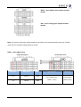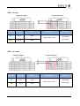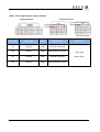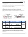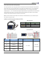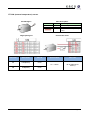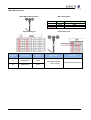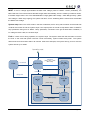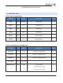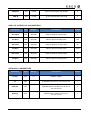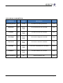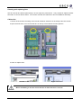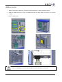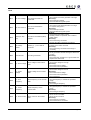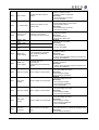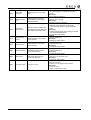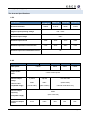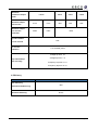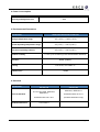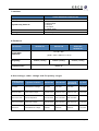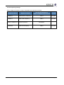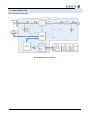
1
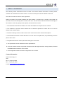
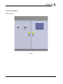
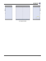
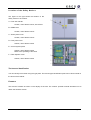
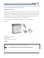
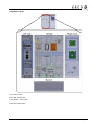
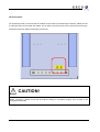
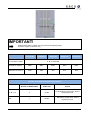
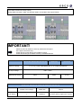
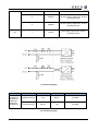
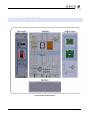
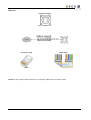
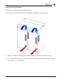
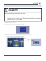
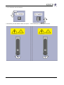
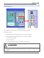
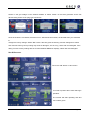
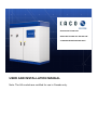
XP100U-H2/ XP100U-H4 XP83U-H6*/ XP90U-H6*/ XP100U-H6* *CANADA CERTIFICATION ONLY USER AND INSTALLATION MANUAL Note: The H6 models are certified for use in Canada only. IMPORTANT SAFETY INSTRUCTIONS SAVE THESE INSTRUCTIONS 1 This manual contains important instructions for the Inverter that shall be followed during installation, operation, and maintenance of the inverter. Warning - These service instructions are for use by qualified personnel only. To reduce the risk of electric shock, do not perform work other than that specified in the operating instructions unless you are qualified to do so. Caution - To reduce the risk of fire, connect only to a circuit provided with 150 (H4 models), 400 (H2 models) and, 125 (H6 models) amperes maximum branch-circuit over current protection in accordance with the National Electrical Code, ANSI/NFPA 70. NOTE: THE H6 models are certified for use in Canada only. Warnings A warning describes a hazard to equipment or personnel. It calls attention to a procedure or practice, which, if not correctly performed, could result in damage to or destruction of part or all of the Inverter equipment and/or other equipment connected to the Inverter equipment or personal injury. DANGER! “DANGER” indicates a hazardous situation which, if not avoided, will result in death or serious injury. WARNING! "WARNING" indicates a hazardous situation which, if not avoided, could result in death or serious injury. 1 Hereinafter referred to as all five Models (XP100U-H2, XP100U-H4, XP100U-H6, XP83U-H6, and XP90U-H6), unless specific model names are indicated. Page 2 CAUTION! "CAUTION" indicates a hazardous situation which, if not avoided, could result in minor or moderate injury. BURN HAZARD! Do not touch. The Inverter contains components that become hot during normal operation. Other Symbols INFORMATION! This symbol accompanies notes that you should know and use to ensure optimal operation of the system. Wiring Requirements All wiring methods and materials shall be in accordance with the National Electrical Code ANSI/NFPA 70, as well as all state and local code requirements. Cable sizes in the chart below are the minimum. Because the field connections are bus bars for accepting crimp lugs, larger cables can be used if needed. Grid Connection XP100U-H4/ XP83U-H6/ HP90U-H6/ XP100U-H6 Number of GRID cables Cable Size Torque A, B, C, N 4 1AWG All 194℉ (90℃) copper wire, 40 lbs-ft tightening torque PE 1 4AWG 194℉ (90℃) copper wire, 40 lbs-ft tightening torque Page 3 XP100U-H2 Number of GRID cables Cable Size Torque A, B, C, N 4 300kcmil All 194℉ (90℃) copper wire, 40 lbs-ft tightening torque PE 1 4AWG 194℉ (90℃) copper wire, 40 lbs-ft tightening torque PV Connection XP100U-H2/ XP100U-H4/ XP83U-H6/ XP90U-H6/ XP100U-H6 Number of PV strings Cable Size Torque 1 600kcmil All 194℉ (90℃) copper wire, 40 lbs-ft tightening torque 2 300kcmil All 194℉ (90℃) copper wire, 40 lbs-ft tightening torque 4 1/0AWG All 194℉ (90℃) copper wire, 40 lbs-ft tightening torque 1 2AWG 194℉ (90℃) copper wire, 40 lbs-ft tightening torque Hot, Return PE Page 4 CONTENTS IMPORTANT SAFETY INSTRUCTIONS ........................................................................................... 2 1. About This Manual ............................................................................................................... 6 2. Safety ................................................................................................................................... 7 3. The blueplanet Inverter Overview ...................................................................................... 13 4. Unpacking .......................................................................................................................... 17 5. Installation & Transportation .............................................................................................. 18 6. Connecting the Conduit ..................................................................................................... 23 7. Electrical Connection ......................................................................................................... 26 8. Connecting User Interfaces ............................................................................................... 34 9. Commissioning .................................................................................................................. 45 10. Opening the Inverter .......................................................................................................... 47 11. Operating ........................................................................................................................... 49 12. Parameters ........................................................................................................................ 53 13. Faults & Warnings .............................................................................................................. 56 14. Maintenance ...................................................................................................................... 60 15. Error Codes ........................................................................................................................ 65 16. Specifications ..................................................................................................................... 69 17. Configuration ...................................................................................................................... 74 18. Certifications ...................................................................................................................... 75 1. ABOUT THIS MANUAL This manual provides information about the Inverter. This manual contains instructions to install, operate, maintain and troubleshoot the KACO Inverter. The user must keep this manual available at all times. This manual contains 5 sections and 3 appendixes. Safety is important. The Inverter operates with high voltages. Improper use or control of the inverter can cause an accident and damage to the inverter or the user. The user must understand directions thoroughly in each section in order to properly install, operate, and maintain the Inverter. 1. The introduction describes the features of Inverter and details the components in the Inverter. 2. The installation & operation section details how to install and operate the Inverter and how to use the Graphic User Interface (GUI). 3. The fault & warning section contains a list of error codes of the Inverter and their descriptions. 4. The maintenance section contains directions on how to clean and replace fans, and periodically check the parts of the Inverter. 5. The parameters section contains parameter settings for the Inverter. A. The specification section details the Inverter specifications. B. The user Interface section will provide information about the digital interface, analog interface, Ethernet and RS485 serial connection of the Inverter. C. The configuration section shows the configuration of the Inverter. Contact Information KACO new energy Inc. USA Tel: +1 (415) 931-2046 Fax: +1 (415) 931-1688 E-mail: [email protected] Page 6 2. SAFETY Appropriate Usage Any other application of the Inverter or installation of components and modifications which are not explicitly allowed endanger the safety and void the warranty as well as the operation permit. A: PV Modules B: String Combiner Box C: Inverter D: AC overcurrent protection E: Grid Basic Solar Power System with the Inverter Page 7 Safety Instructions DANGER! High voltages are present in the live components of the low voltage grid. Death may result from burns and electric shock. Do not touch the live components of the Inverter or low-voltage grid. Pay close attention to all safety precaution measures regarding the low voltage grid. Page 8 DANGER! During operation, high voltages are present in the Inverter. Death may result from burns and electric shock. Before commencing work on the Inverter disconnect completely and ensure that the device will not be accidentally energized. Ensure that no voltage is present. Ground and short-circuit. Cover any nearby live parts. DANGER! Normally grounded conductors may be ungrounded and energized when a ground-fault is indicated. Risk of electric shock. Test before touching. Contact customer support for information at KACO new energy, Inc. +1 (415) 931-2046. WARNING! Failure to follow the manual, the operating instructions and the safety precautions may lead to severe injury from electrocution. All work on the Inverter may only be done as described in this manual and must be performed by qualified personnel. Pay attention to all safety instructions. Follow all operating instructions. If problems occur when performing the work described here, contact the customer support department at KACO new energy Inc. +1 (415) 931-2046. Page 9 WARNING! Operating the Inverter if it’s damaged may cause severe injury from electrocution. The Inverter may only be used when it is functioning correctly. Regularly check the XP Inverter for visible damage and operate only if there is no visible damage. Ensure that all safety features are accessible at any time and that their correct operation is tested regularly. ATTENTION! The printed circuit board (PCB) components in the Inverter can be damaged by electrostatic discharge! When working on the Inverter and when handling the PCB components observe all ESD safety regulations. Discharge electrostatic charge by touching the grounded Inverter enclosure. Only then is it safe to touch any electronic components. Technical rules The installation must be in compliance with the local regulations and technical rules, in particular with regard to electrical connections. (National Electric Code NEC) The installer is responsible for knowing and understanding local standards and regulations as well as utility interconnection requirements. Page 10 Regulations concerning the prevention of accidents During the operation of the inverter, certain parts of the device carry high voltages, which may lead to severe personal injury or even death. The following precautions should be followed to minimize the risk of lethal hazards or personal injuries. The installation of the device must be in compliance with the relevant safety regulations or other applicable national or local provisions. Proper ground, conductor dimensioning and an appropriate short-circuit protection must be provided to ensure operational safety. All instrument covers must remain closed during operation. Prior to performing some visual checks and maintenance work the inverter must be disconnected from all power sources and protected against inadvertent activation. If measurements have to be conducted while the inverter is connected to power, NEVER touch live terminals. Remove all jewelry from your wrists and fingers. Ensure that the test equipment is in a proper and safe operating condition. When working on the inverter while energized, make sure to stand on an insulated surface and ensure that there is no connection to ground. Follow the instructions exactly as given in these operating and installation instructions and especially observe all information concerning possible hazards, warnings and precautions. This manual may not cover all possible scenarios. Should a specific problem occur that is not sufficiently explained, please contact your dealer or KACO new energy. Modifications/Changes CAUTION! Hazard of damage due to unauthorized modifications/manipulation! By no means manipulate the inverter or modify or change the inverter or any other parts of the installation Performing any modifications or changes on the inverter is generally prohibited. Performing any changes or modifications to the installation of the inverter is only permitted if in compliance with national standards and performed by qualified personnel. Page 11 Inverter shutdown WARNING! Hazardous live voltages can be present in the inverter even if the electrical connections are switched off or disconnected. Please wait for 1 minute before accessing the inverter The inverter must be switched off for adjusting, maintenance and repair work. Please proceed as follows: 1. Turn the inverter off by pushing the off button in the GUI. 2. Turn the AC and DC switches to the OFF position a. (The off position is green and the on position is color coded red). 3. Disconnect the inverter from the PV array. 4. Disconnect the inverter from the grid. 5. Check that the inverter is disconnected from all voltage sources. 6. If possible Install lockout devices on the utility connection circuit breaker, AC and DC disconnect switches. 7. Wait 1 minute for all capacitors inside inverter to discharge. 8. When reactivating the XP inverter expect a five minute commission window. Page 12 3. THE BLUEPLANET INVERTER OVERVIEW Full digital control using digital signal processing (DSP) The KACO XP uses two DSPs to control the inverter and an ARM processor for user and external interface. These full digital control schemes offer enhanced reliability, accuracy, efficiency, flexibility and convenience. High reliability The KACO Inverter features built in reliability with redundant power supplies, highly efficient cooling of critical components and intelligent cooling fans. The fans are monitored and controlled according to load and environmental temperature conditions. All components used in the KACO XP are designed for industrial use. The IGBT stack was designed based on the IEEE WG PEBB TF2 standards. These standards mandate the use of laminated DC bus-bars that provide for very low stray inductance and gate drive interfacing with differential signaling. This feature enhances reliability and ease of maintenance. Full digital control technology of the XP also enhances reliability by reducing component count compared to traditional analog electronics. Powerful human interface and networking The Inverter’ features a powerful and friendly Graphic User Interface (GUI). The “all-in-one” design for the GUI provides for more convenient operation and monitoring. The GUI is a big, easy to use display with color TFT LCD (480 x 272 dots) and provides detailed operating information in different languages. RS232, RS485, and Ethernet interfaces for networking are standard in the Inverter. System flexibility The Inverter provides 4 analog inputs, an S0 input, 1 programmable dry contact output A type (Normally open) and B type (Normally closed), and 1 digital input. The analog inputs are preconfigured for the user and allow easy connection of temperature sensors and a reference cell. The S0 input is preconfigured for smart metering. . Page 13 Shape & Components External shape Front Page 14 Left, Right and Back Page 15 Location of the Safety Notices The figure to the right shows the location of the safety notice on the Inverter. A. Front door handle. Caution, risk of electric shock, hot surface B. PEBB cover Caution, risk of electric shock C. Switch panel cover Caution, risk of electric shock D. Fuse panel cover Caution, risk of electric shock E. Control system panel Caution, risk of electric shock Refer to the operating instructions F. Filter capacitor cover Caution, risk of electric shock The Inverter identification You can identify the Inverter using the type plate. The inverter type identification plate can be found inside on the doors of the cabinet. Firmware The Inverter’ firmware is shown on the display of the GUI. The Inverter’ operator manual describes how to obtain the firmware version. Page 16 4. UNPACKING This section describes unpacking and inspection of the inverter. Unpacking and inspection All KACO inverters are thoroughly inspected before packing. Although they are shipped in sturdy packaging, damage can still occur during shipping and delivery. It is important to carefully inspect the shipping container and contents prior to installation. When you detect any external damage before or after unpacking, report the damage immediately to your KACO dealer and the shipping company that delivered the unit. If it is necessary to return the Inverter, please use the original packing material. If you need assistance with damaged inverter, contact your dealer or KACO new energy Inc. Contents A: Inverter B: User and Installation Manual C: Test Report D: Keys for GUI cover and front door Storage ATTENTION! The inverter should be properly stored to ensure optimal performance. The inverter should be closed when stored to protect from dust and moisture. If the storage period is longer, the inverter should be kept in a dry place. Page 17 5. INSTALLATION & TRANSPORTATION Selecting an appropriate place of installation If possible the inverter should be installed in an area that is as dry as possible. This is to ensure maximum product longevity. Additionally, if the ambient temperature at the installation site is above or below the specifications designated by the manufacturer, the inverter should then be mounted indoors where the ambient temperature can be controlled within the specifications. Again, this is in order to ensure maximum product longevity. The following rules should be observed while choosing the site for the installation of your inverter: 1. Ensure good access for assembly or service work. 2. Please ensure free air circulation at the sides of the housing. 3. The place of installation must ensure proper heat dissipation. If necessary, provide forced ventilation of the room to ensure that heat is dissipated adequately. 4. Ensure that the supporting area has an adequate load-bearing capacity. Weights and Dimensions XP100U-H2: Weight: 1400Kg XP100U-H4: Weight: 1400Kg XP83/90/100U-H6: Weight: 1100kg The installation site must be easily accessible for installation or service work and should preferably not expose the inverter to direct sunlight or enclose the inverter in an unventilated space. Page 18 Minimum Workspace Requirements The minimum clearance space shown below should be maintained for ventilation and access. * * If you use a left side conduit plate, the minimum clearance is 4 inches on the left side for installation but actual clearance will be dictated by the requirements of conduit fitting installation and maintenance accessibility. Installation Site Requirements The foundation must guarantee a solid and safe surface to bear the weight of the inverter. Page 19 Preparation of the mounting surface Prepare the mounting surface structure appropriately based on the chosen site Secure the Inverter to the chosen site with the pre-installed L-brackets. Position of the mounting holes (bottom view) Page 20 Foundation L-bracket surface mount Mounting L-bracket to the inverter L-bracket for mounting Transport Instructions Please note the weight of the inverter and follow the instructions below. The mode of transportation must support the weight the inverter. During transport be certain to center the weight of the inverter as the center is closer to the left side. Do NOT tilt the inverter while transporting. The pictures below are examples for transportation. Page 21 Fork lift from front or rear Crane fork from front or rear Eye nuts with crane rack Slope angle = 0° in any direction Page 22 6. CONNECTING THE CONDUIT In this section, see how to insert the cables in the inverter and where to punch the holes for the conduit fittings. NOTICE! When installing, please be cautious that water is not able to enter into the inside of the cabinet. Only recognized NEC compliant watertight conduit and fittings must be used for outdoor applications. Moisture can affect the performance of the inverter through improper conduit or hubs. How to install the cables There are two ways of connecting cables shown in the following figures. The field wiring area is designed for DC cable, AC cable and data cables. The conduit entry points can be used for any cables. Example: Left side for DC conduit and bottom for AC conduit. Using the left side panel for cables 1. Remove the bolts which secure the plate to the inverter. 2. Remove the plate. 3. Mark all the holes for the conduit. You need conduit for the AC, DC and data cables. 4. Punch holes for the conduit. 5. Attach the plate to the Inverter. 6. Attach the bolts and tighten. 7. Attach the conduit with the appropriate conduit fittings. a. Ensure that proper conduit duct sealant is used to prevent rodent and insect infestation. b. The bottom plate must be secured in place during operation. If conduit is used, the proper conduit fittings must be used. Page 23 Left panel dimensions for conduit Page 24 Using the bottom panel for conduit Bottom access panel for conduit Page 25 7. ELECTRICAL CONNECTION The electrical connections should only be made after the inverter has been installed in its final location. To complete the electrical connections, the AC and DC terminal connections must not be connected to any source of voltage. This will protect the installer from harm and ensure that the inverter is not accidentally activated. CAUTION! After the inverter has been installed in the fixed location, the electrical connection can be established Please be sure that both AC and DC side are disconnected from all voltage sources. Please be sure that the switches are locked out and switching-on unintentionally is not possible. NOTICE! The electronic printed circuit board components in the inverter can be damaged by static electricity. When handling the printed circuit boards, please follow ESD safety regulations. To prevent the damage from static electricity, touch the enclosure of the grounded inverter. Please go to the next step when you are sure it is safe. Page 26 Connection Area D D A: AC Connection B: DC Hot Connection C: DC Return Connection D: Ground Connection Page 27 PE Connection PE (Protective Earth) or Ground rails are located on both sides of the field wiring enclosure. Please ensure the Ground rails are connected with cables. Any of these connection points can be used for the Grounding Electrode Conductor (GEC) and bonding conductors. CAUTION! Before connection, please check that all external cabling is connected properly and not able to be energized accidentally. Page 28 Grid Connection The inverter is connected to the grid through AC bus bars which are located on the left bottom of the field wiring area of the inverter which are labeled A, B, C, and N. The minimum cable size is 1 AWG for both H4 and H6, and 300kcmil for the H2 model. The torque value for AC terminal connections is 40 lb-ft. The maximum AC overcurrent protection is 125A for the H6 model, 150A for the H4 model, and 400A for the H2 model. NOTE: The AC service must be a three phase wye connection and the neutral conductor must be used. DANGER! Electric shock can result from handling the components with high-voltage present. Please be sure that all voltage sources are disconnected and cannot be accidentally energized. CAUTION! The inverter AC connections must have the proper phase rotation in order to connect to the grid and operate. Proper rotation is A-B-C. Please check with a phase rotation meter. If the phase rotation is incorrect an error will be displayed on the user interface and the inverter will not connect to the grid, if this happens reverse any two phases to correct the rotation. Page 29 IMPORTANT! Please check that the cables are connected and torqued properly. Use 90℃ copper conductors only. XP100U-H2 XP100U-H4 AC connection cable XP83U-H6 XP90U-H6 XP100U-H6 A, B, C, N and PE Nominal AC voltage 208V 480V 600V 600V 600V Maximum AC current 278A 120A 80A 87A 96A XP100U-H4/ XP83U-H6/ XP90U-H6/ XP100U-H6 Number of GRID cables Cable Size Torque A, B, C, N 4 1AWG All 194℉(90℃) copper wire, 40 lb-ft tightening torque PE 1 4AWG 194℉(90℃) copper wire, 40 lb-ft tightening torque Page 30 XP100U-H2 Number of GRID cables Cable Size Torque A, B, C, N 4 300kcmil All 194℉(90℃) copper wire, 40 lb-ft tightening torque PE 1 4AWG 194℉(90℃) copper wire, 40 lb-℉t tightening torque PV Connection PV Array is connected to the inverter through the DC input bus bars which are located on the bottom right of the field wiring area of the inverter. CAUTION! Risk of damage! Make sure NOT to reverse polarity of the DC input. DANGER! Ensure protection against hazardous live voltages during the assembly of the PV installation. Both positive and negative leads must be correctly isolated. CAUTION! Page 31 Each cable is related to certain polarity. During cable connection, make sure that the cable is connected to the proper location DC Port for Negative ground system DC Port for Positive ground system IMPORTANT! Please check if all cables are securely fastened and torqued. Use copper conductors only. Check that all conduit fittings are installed correctly. Check that all fittings are sealed correctly if installed outdoors. XP100U-H2/ XP100U-H4/ XP100U-H6 XP83U-H6 XP90U-H6 Number of strings 1, 2, 3 or 4 (1 fuse is standard and 2, 3, or 4 fuses are optional) DC input voltage 300V ~ 600V Maximum DC current 350A 290A 317A XP100U-H2/ XP100U-H4/ XP83U-H6/ XP90U-H6/ XP100U-H6 Hot, Return Number of PV strings Cable Size 1 600kcmil Torque All 194℉ (90℃) copper wire, 40 lb-ft Page 32 tightening torque PE 2 300kcmil All 194℉ (90℃) copper wire, 40 lb-ft tightening torque 4 1/0AWG All 194℉ (90℃) copper wire, 40 lb-ft tightening torque 1 2AWG 194℉ (90℃) copper wire, 40 lb-ft tightening torque Connection Diagram Model Name Ground System PV(+) Terminal PV(-) Terminal DC Ground Terminal XP100U-H2 XP100U-H4 XP83U-H6 XP90U-H6 XP100U-H6 Negative Ground Hot Return PV GND Positive Ground Return Hot PV GND DC Terminal Polarity Page 33 8. CONNECTING USER INTERFACES User Interface of the Inverter Page 34 UDIO – User digital input output terminal blocks UAI – User analog input output terminal blocks Note: On some inverters the exact location of the wires in the terminal blocks may vary. Please verify the wire numbers using the given charts. UDIO – User digital input Target port figure Connect the wires Port num. Port name Wire # 1C UDI1 P C300 1D UDI1 N C299 Specification Wire size Dry contact input 18-24 AWG (24Vdc, 10mA) (0.82-0.20㎟) Page 35 UDIO – S0 input Target port figure Connect the wires Port num. Port name Wire # 2C S0in P C301 Specification Wire size 18-24 AWG MAX 27Vdc, 27mA 2D S0in N (0.82-0.20㎟) C302 UDIO – S0 output Target port figure Connect the wires Port num. Port name Wire # 3C S0in P C303 Specification 18-24 AWG MAX 27Vdc, 27mA 3D S0in N C304 Wire size (0.82-0.20㎟) Page 36 UDIO – User digital output (relay contacts) Target port figure Connect the wires Normally Open Port num. Port name Wire # Specification 4C UDO1A C305 External output N/O 4D UDO1C C306 External output common 5C UDO1B C307 External output N/C 5D UDO1C C308 External output common Normally Closed Wire size 18-24 AWG (0.82-0.20㎟) Page 37 RS 485 terminal blocks The Inverter provides two RS485 interfaces. RS485-1 communicates with the control board (XCU) and is reserved for future use. RS485-2 communicates with the GUI and is used for standard datalogger monitoring. The connection method for each RS 485 port is detailed below. Note: Not all RS485 systems use the A and B signals in the same way thereby reversing the polarity. On some applications, if there is no communication, reversing the polarity will allow communication. Note: On some inverters the exact location of the wires in the terminal blocks may vary. Please verify the wire number in the given charts. RS485-1 (Future Use) connections Target port figure Connect the wires ▶ To add termination resistance, a jumper should be connected between 1D and 2C. Port num. Port name Wire # Specification 1C RS485A1 C322 RS485 signal A1 1D RS485B1 C323 RS485 signal B1 2C RS485C1 C324 Termination resistance setup port 2D RS485G1 C325 RS485 communication GND1 Wire size 18-24 AWG (0.82-0.20㎟) Note: Termination resistance should only be used at the beginning and the end of the RS485 chain. Page 38 RS485-2 (Data logging) Target port figure Connect the wires ▶ To add termination resistance, a jumper should be connected between 3D and 4C. Port num. Port name Wire # Specification 3C RS485A2 C326 RS485 signal A2 3D RS485B2 C327 RS485 signal B2 Wire size 18-24 AWG 4C RS485C2 4D RS485G2 C328 Termination resistance setup port C329 RS485 communication GND2 (0.82-0.20㎟) Note: Termination resistance should only be used at the beginning and the end of the RS485 chain. Page 39 UAI terminal blocks (User Analog Inputs) The Inverter provides 4 user analog input interface connections and 4 extra terminal blocks are provided as well for further uses. The User analog inputs are connected to an Irradiation sensor, a PV cell temperature sensor, and a PT1000 temperature sensor and a Wind Speed sensor. The user analog input interface voltage range is 0 ~ 10V. The terminal block diagrams depicted below are representative of inverters with the optional 24VDC power supply. If the inverter does not have the optional power supply, the wire numbers should be used to identify the proper connections for the sensors. Note: On some inverters the exact location of the wires in the terminal blocks may vary. Please verify the wire number in the given charts. Irradiance and Cell temperature Sensor (Si-12TC) Si-12TC figure Wire description Wire Target port figure Color Red Black Yellow Brown Black Specification VCC(12~24Vdc) GND Irradiation value(0-10V) Cell Temperature(0-10V) Frame GND Connect the wires Port num. Port name Wire # 1C IVP(Yellow) C311 1D IVN(Black) C310 Specification Wire size 18-24 AWG 0V ~ 10Vdc 3C CTP(Brown) C312 3D CTN(Black) C313 (18-24 AWG㎟) Page 40 PT1000 (external temperature) sensor PT1000 figure Wire Target port figure Connect the wires Port num. Port name Wire # 5C PTP(Brown) C314 5D PTN(Black) Wire description Color Specification Red VCC(15~24Vdc) Black GND Brown Ambient Temperature(010V) C315 Specification Wire size 0V ~ 10Vdc 18-24 AWG (0.820.20 ㎟) Page 41 Wind Speed sensor Wind Speed Sensor figure Wire description Wire Target port figure Port name Wire # 7C WSP(Black) C316 WSN(Brown) Specification VCC(5~24Vdc) GND Signal Connect the wires Port num. 7D Color Red Black Brown C317 Specification Wire size Wind Speed signal (0Hz~125Hz) 18-24 AWG (0.82-0.20㎟) Page 42 To get the most accurate data from the analog interface, the user must calculate gain and offset. Then the user must change the parameters of the Inverter. The symbols for gain and offset are listed here: Ml: lower limit of analog input by sensor. Mu: upper limit of analog input by sensor. Dl: lower limit of displayed value. Du: upper limit of displayed value. M: input value in range of Ml and Mu. D: displayed value in range of Dl and Du. Gain: G= (Du –D1) / (Mu – M1) Offset: O = D1 – (G x M1) Displayed value: D = (G x M) + O After calculating gain and offset, the user must change the values through the GUI or use the CMT (change the settings in the analog tab located in parameter panel). CAUTION! Voltages > 10Vdc or reversed polarity may lead to damage of the sensor input circuits IMPORTANT! System will show unexpected values if gain and offset are not properly set. Ensure that calculations are exact. Page 43 Ethernet Target port figure Connect the wires Connector Type Cable Type RJ45 Direct (1:1) NOTE: If using a direct cable connection to a computer, please use a crossover cable. Page 44 9. COMMISSIONING DANGER! Electric shock is possible from improper startup of the Inverter. Death may result from burns and electric shock. l All procedures described in this section may only be conducted by qualified personnel. If problems occur when performing the work described here, contact the technical support dept. at KACO new energy Inc. +1 (415) 931-2046. Visual Inspection Inspect all large power cables and bus connections throughout the inverter to verify that they are tight. Verify that all PV wires are connected with the proper polarity and tightened to the proper torque specification. Check the AC connections for proper phase rotation and that they are tightened to the proper torque specification. Verify that the AC and DC ground wires are connected correctly and tightened to the proper torque specification. Inspect the interior of the Inverter to insure that it is clear of tools, foreign objects, water, debris or documents. Page 45 How to check the Ventilation The Inverter is cooled by top quality variable speed fans. In the Inverter, air flow is from the top front and expelled at the bottom in the front and back. 1. Check the ventilation air flow by placing a sheet of paper near the vents to ensure air is flowing. 2. If the Inverter does not suck air in or does not blow it out, contact the technical support dept. at KACO new energy Inc. +1 (415) 931-2046. Page 46 10. OPENING THE INVERTER DANGER! Electric shock is possible from improper startup of the Inverter. Death may result from burns and electric shock. l All procedures described in this section may only be conducted by qualified personnel. If problems occur when performing the work described here, contact the technical support dept. at KACO new energy Inc. +1 (415) 931-2046. Opening the Inverter cabinet 1. Insert the key into the GUI lock and open the GUI cover. 2. Press the ‘OFF’ button on screen for the Inverter to turn off and wait 1 minute. Page 47 3. Turn off the DC and AC switches. 4. Put the key into the cabinet’s locks and open it. – The handle flips up then turns the handle. Page 48 11. OPERATING Startup Instructions Part 1 Part 3 Part 2 Inside of the Inverter After installation and electrical connection, the Inverter will be ready for operation. Follow these instructions. • Check that the switches in the part1 are turned on. If not, turn on the switches. • Check that the switches in the part2 are turned on. If not, turn on the switches. • Turn on the switch in the part3. • Close the cabinet doors. • Turn on the AC and DC, and disconnect switches on the left cabinet door. DANGER! High voltage may be present inside inverter. When turning off or on the switches, be careful not to touch conductors. Page 49 Switch on the grid voltage via the external breaker or switch. Switch on the solar generator via the DC disconnecting switch or DC plug-type connectors. Once the inverter is connected, the GUI turns on. After about two minutes, the GUI will ask if you would like to change the country settings. Select "NO". Note: If the GUI gives the warning "Current settings don't match and countries. Wrong country setting may result in damage!!", this is a bug , select 'Ok' and disregard. If the dialog "Current country settings are set to USA CANADA MEXICO" displays, select "OK" and disregard. See GUI screen. Touch the “ON” button on GUI screen. If no fault is present the inverter will begin operation. The inverter will start operating and GUI icons will be green. Page 50 GUI during proper operation IMPORTANT! The inverter can’t be started when a fault is present. Use the ‘fault reset’ procedure and retry the start operation. Refer to the ‘Fault & Warning’ section for a description of the ‘fault reset’ procedure. If the GUI gives a Code F16 or 'Inv. Phase Order' failure message, the phase rotation is reversed. Shut down the system, power off all AC and DC voltage to the inverter, and reverse the phase A and B connections on the AC field wiring terminals. CAUTION! If the fault isn`t resolved after ‘fault reset’ procedure is complete, contact the KACO technical dept. at +1 (415) 931-2046 Operating State The Inverter has eight operating states. The explanations about each state are below. Disconnected (default): Before operation has commenced the inverter is in the disconnected state. In this state, the inverter is totally isolated from the PV array and the utility grid. Connecting to the PV array: When the inverter is in the "Disconnect" state, the ‘Inverter On’ button on the GUI is selected and the PV voltage is kept above 200V for 5 seconds, the system turns on the PV Array side contactor (PV_MC). In this state, if the PV voltage falls below 100V, the inverter returns to the Disconnect state. Connecting to Grid: When the inverter is in the “Connecting to PV Array" state and the PV voltage is kept above the value of “MPPT V Start” parameter during the time set by “MPPT T start” parameter, the contactor on the grid side is turned on. The inverter keeps this state for 8 seconds. Initializing MPP: The inverter calculates the MPPT start voltage which is product of measurement of PV voltage and the parameter “MPP Factor”. After 5 seconds, the inverter system enters into the "MPP start" state. MPP start: In this state, the inverter controls the PV voltage. Reference of the PV voltage (“Vdc reference” parameter) the inverter changes from “open circuit” voltage to the value of the “MPPT V start” parameter. Page 51 MPPT: If the PV voltage approximates the MPP start voltage (value of “MPPT V Start” parameter), the MPPT will start. The inverter follows the MPP target value automatically, which is varied by irradiance values. If the MPP target value is out of the allowable MPPT range ([MPP start voltage – MPP Range lower] ~ [MPP start voltage + MPP range upper]), the system will return to the “Initializing MPP” state and will recalculate the MPPT start voltage. System stop: When the “OFF” button in the GUI is selected, the PV Array side contactor and the Grid side contactor are turned off and the system stops. If the output power of inverter is kept below value of “MPPT P stop” parameter during time of “MPPT T stop” parameter, connection to the grid is terminated. In addition, If PV voltage is below 100V, the inverter stops. Fault: If a fault occurs during operation, the system stops. The system resets the fault and tries to remove the fault. In the case that system removes a fault successfully, system restarts all by itself. The system allows three auto fault resets within 30 minutes. After three attempts, the system will log an error and the system will not try to restart. Operating start Fault Fault Reset Inverter On [200 <= Vpv <= 630 && T>5 sec] PV_MC (K10) ON Disconnect (2) [Vpv<200 && T>120 sec] [Vpv >= {Vpv_start} && T > {Tstart}] Inverter Off Heavy Fault [Ppv < {Pstop} && T > {Tstop}] MPPT (6) [Out of range] Grid_MC ON (3) [T > {Tbuildup} + 3.5 sec] [Vpv == MPP Ref.] MPP Start [Vpv>Vmpp_min && T > 5sec] MPP Init. Page 52 Operating states chart of the Inverter 12. PARAMETERS DATE-TIME PARAMETERS Parameters Units Ranges Descriptions Default Year N/A 2000~3000 Current year. - Month N/A 1~12 Current month. - Date N/A 1~31 Current day. - Time N/A 0~23 Current hour Minute N/A 0~59 Current minute. Second N/A 0~59 Current second. DIGITAL INTERFACE PARAMETERS Parameters Units Ranges Descriptions Default DI1 Select N/A 0~20 Selection for digital input1 0 DO1 Select N/A 0~20 Selection for digital output1 0 DO2 Select N/A 0~20 Selection for digital output2 0 Power Meter kWh 0~99999999 RS485 Protocol N/A 0~999 0 0 : ACI protocol 0 1 : Protocol for the prolog 2 : Protocol for the PVI-go Page 53 RS485 ID N/A 0~999 ID for communication with RS485 0 CAN ID N/A 0~999 ID for communication with CAN 0 ANALOG INTERFACE PARAMETERS Parameters Units Ranges Descriptions Default AI1 Offset N/A -300~300 Value of offset for analog input1 0 AI1 Gain N/A -300~300 Value of gain for analog input1 120 AI2 Offset N/A -300~300 Value of offset for analog input2 20 AI2 Gain N/A -300~300 Value of gain for analog input2 10.87 AI3 Offset N/A -300~300 Value of offset for analog input3 50 AI3 Gain N/A -300~300 Value of gain for analog input3 10 NETWORK PARAMETERS Parameters Units Ranges Descriptions Default Config N/A 0,1 0:DHCP 1:Static 1 IP N/A IP address in the form of “xxx.xxx.xxx.xxx” 1 Netmask N/A Netmask used for the Network. Its form is “xxx.xxx.xxx.xxx” 0 Gateway N/A Address for the router in the form of “xxx.xxx.xxx.xxx” 1 Page 54 RECORDING PARAMETERS Parameters Units Ranges Descriptions Default Recording Interval min 10~60 A period for recording parameters 10 Grid Power N/A On(1), Off(0) If off the Grid power isn’t recorded On(1) PV Power N/A On(1), Off(0) If off the PV Power isn’t recorded On(1) PV Voltage N/A On(1), Off(0) If off the PV Voltage isn’t recorded On(1) PV Current N/A On(1), Off(0) If off the PV current isn’t recorded On(1) PV Temp. N/A On(1), Off(0) If off the PV Temperature isn’t recorded On(1) Irradiation N/A On(1), Off(0) If off the Irradiation isn’t recorded On(1) Delete All Statistics N/A N/A Delete all statistics data. N/A Page 55 13. FAULTS & WARNINGS When a problem occurs in the system, the Inverter will beep and inform the user on the GUI. The Inverter displays two basic error messages. The first, the fault, is a serious problem that causes the inverter to stop running. The second, a warning, is a minor problem that does not cease the system operation. The GUI will indicate faults in red and warnings in yellow. The user can find a description of the different fault and warnings in the following tables. WARNING AND FAULT TABLES Warning Message Code Description SP1(PV SP) Failure W01 Failure of the PV side surge protector(SP1) Reserved W02 Reserved PV Fuse Failure W03 PV side Fuse failure(option) Ground Fault Warning W04 The insulation resistance of the PV falls short of the limit set in the ground fault monitoring for Alert1(option) Reserved W05~W19 Reserved PEBB Over Temp. Warning W20 The temperature of the PEBB(Power Electronics Building Block) heatsink exceeds 75℃(167℉) PEBB Fan Failure W21 Failure of a PEBB(Power Electronics Building Block) fan Reserved W22~W29 Reserved SP2(Grid SP) Failure W30 Failure of the grid side surge protector(SP2) Reserved W31~W39 Reserved Test Mode W40 The system is working in test mode Page 56 Reserved W41~W49 Reserved Cabinet Over Temp. Warning W50 The temperature of the cabinet exceeds the operational parameter [Cabinet Temperature Maximum] Cabinet Under Temp. Warning W51 The temperature of the cabinet falls below the operational parameter [Cabinet Temperature Minimum] Reserved W52~W53 Reserved Control SMPS Failure W54 Failure of the control SMPS (Switching Mode Power Supply) Reserved W55 Reserved Fan SMPS Failure W56 Failure of the fan SMPS (Switching Mode Power Supply) Reserved W57 Reserved Cabinet Fan Failure W58 Failure of a cabinet fan Fault Message Code Description PV Over Voltage F01 PV voltage exceeds the parameter [DC over voltage Level] PV Over Current F02 PV current exceeds the parameter [DC over current Level] PV Under Voltage F03 Voltage of the DC input is below the minimum running voltage K10 (PV Contactor) Failure F04 PV side contactor (K10) failure PV Polarity Failure F05 Polarity (+, -) of PV side is reversed Ground Fault F06 PV side ground fault S10(PV Switch) Trip F07 S10 (PV Disconnect Switch) tripped during operation Reserved F08~F09 Reserved Page 57 Inv. Over Voltage F10 Over voltage on the inverter side Inv. Under Voltage F11 Under voltage on the inverter side Inv. Over Frequency F12 Over frequency on the inverter side Inv. Under Frequency F13 Under frequency on the inverter side Inv. Over Current F14 Over current on the inverter side MC21(Inv. MC) Failure F15 Inverter side contactor (MC21) failure Inv. Phase Order F16 Phase order failure on the inverter side, wrong phase rotation Inductor or TR Over Temp. F18 Inductor or Transformer temperature is above 150 C Reserved F19 Reserved PEBB 1 IGBT Fault F20 PEBB 1 IGBT failure PEBB 2 IGBT Fault F21 PEBB 2 IGBT failure PEBB 3 IGBT Fault F22 PEBB 3 IGBT failure Reserved F23 Reserved PEBB Over Temp. Analog F24 The temperature of the heat-sink exceeds 90℃ (194 F). PEBB Over Temp. Digital F25 The heat-sink temperature generated by the thermal trip device has exceeded operational parameters (Thermal Switch) Reserved F26~F29 Reserved Grid Over Voltage F30 Over voltage on the grid side Grid Under Voltage F31 Under voltage on the grid side Grid Over Frequency F32 Over frequency on the grid side Page 58 Grid Under Frequency F33 Under frequency on the grid side CB20(Grid SW) Trip F34 CB20 (AC Disconnect/Grid circuit breaker) was tripped during operation Reserved F35~F39 Reserved Parameters Version Error F40 Different version between the NVSRAM parameter table and the program parameter table Flash Memory Failure F41 C6000 DSP program flash memory failure in XCU (main control) board FPGA Failure F42 FPGA failure in XCU (main control) board DSP28x Failure F43 F2000 DSP failure in XCU (main control) board ADC Failure F44 ADC block failure in XCU (main control) board Reserved F45~F49 Reserved Emergency Stop F50 A door is open Cabinet Over Temp. F51 Temperature of cabinet is too high. Inverter has stopped operation Page 59 14. MAINTENANCE Insulating gloves must be used during maintenance. The Inverter needs to be periodically maintained. IMPORTANT! All service MUST be done by authorized personnel only. DANGER! DC terminals may be energized. Allow ten minutes for all capacitors within the main Enclosure to disch arge after disconnecting the Inverter from AC and DC sources. Before touching any electrical connectio ns make certain that no hazardous live voltage is present. Page 60 De-Energize/Isolation Procedure The following procedure should be followed to de-energize the Inverter for maintenance. To isolate the Inverter: 1. Turn the main ON/OFF switch in the GUI to the OFF position. 2. Open the utility connection circuit breaker. 3. Open the AC Disconnect. 4. Open the DC Disconnect Switch. 5. Install lockout devices on the utility connection circuit breaker, AC and DC disconnect switches. 6. Before touching any electrical connections make certain that no hazardous live voltage is present. Maintenance includes: A. Inspection of parts which may become worn and repairing or exchanging them B. Functional testing of components C. Inspection of connections D. If needed - cleaning of the cabinet exterior / interior NOTE: Maintenance frequency is dependent on the location and environmental conditions. The Inverter can function in dusty environments but must be maintained more frequently than is recommended in the following table. Page 61 Time intervals for maintenance work Maintenance work maintenance interval (recommended) Cleaning or replacing of the filter mats in the air intake 6 months * Clean the heat sink-power section 12 months * Inspection of a cabinet for strong dust sedimentation, pollution, moisture and water penetration from the outside. 12 months Inspection of all warning labels, replace if necessary. 12 month Function test of the fans 12 month Visual inspection of fuses, breakers and surge protection 12 month Visual inspection of redundant auxiliary power supplies 12 month Function test of the door contacts 12 month Inspection of the run and fault indicators 12 month * If the installation site is especially dirty, maintenance intervals will be reduced. Page 62 Cleaning and replacing fans The fans should be cleaned periodically to ensure optimum performance. They should be replaced and/or serviced if an air flow issues arises. The Inverter includes two cabinet fans and one PEBB fan assembly. Cabinet fan 1. Switch off the inverter according to the inverter shutdown directions in the safety instruction section. 2. Open the front doors. You can find the fans on the top of the cabinet as below pictures. 3. Clean or replace fans. Left cabinet fan Right cabinet fan When assembling a new fan ensure that the air flow direction is correct! Caution! Page 63 PEBB fan assembly 1. Switch off the inverter according to inverter shutdown direction in safety instruction section. 2. Open the PCB module doors. Find the PEBB fans under the IGBT stack as shown in the pictures below. 3. Clean or replace fans. When assembling a new fan ensure that the air flow direction is correct! Caution! Page 64 15. ERROR CODES The Inverter can detect faults during operation. The inverter will display the fault in the GUI. Faults are indicated in the GUI with an error code, and a plain text message with the error code and system plant name in the text line will be sent to the system operator (only available if purchased and configured during setup). This section describes how to recognize the types of faults and how to correct these faults. Warnings Code Message Warning description W01 SP1(PV SP) Failure Failure of the PV side surge protector (SP1) W03 PV Fuse Failure PV side Fuse failure(option) W20 PEBB Over Temp. Warning The temperature of the heat-sink of the PEBB exceeds 75°C (167°F) W21 PEBB Fan Failure PEBB heat-sink fan failure W30 SP2(Grid SP) Failure Failure of the grid side surge protector (SP2) W40 Test Mode The system is working in test mode W50 Cabinet Over Temp. Warning The temperature of the cabinet exceeds operational parameters W51 Cabinet Under Temp. Warning The temperature of the cabinet falls below operational parameters W52 Control SMPS Failure Failure of the control SMPS Possible causes/Diagnosis Problem • Lightning strike on or near the PV system wiring Solution(s) • Visual inspection • Change the SPD Problem • PV system wiring short • Short circuit in the IGBT Solution(s) • Check the input current • Check module wiring • Change the FUSE Problem • PEBB Fan Failure Solution(s) • Clean the filters or PEBB heat-sink fins • Change the PEBB Fan Problem • PEBB Fan Failure Solution(s) • Change the PEBB Fan Problem • Lightning strike on or near the grid system wiring Solution(s) • Visual inspection • Change the SPD Problem • The system is working in test mode Solution(s) • Change the parameters in the GUI Problem • Cabinet Fan Failure Solution(s) • Clean the air filters • Change the cabinet fan Problem • Ambient temperature is too low for operation Possible causes • Failure of the control SMPS Solution(s) • Change the control SMPS Page 65 Fault Code Message Warning Description F01 PV Over Voltage PV voltage exceeds the parameter F02 PV Over Current PV current exceeds the parameter F04 CB10 (PV CB) Trip PV side circuit breaker(CB10) tripped F05 PV Polarity Failure Polarity (+, -) of PV side is reversed F06 Ground Fault PV side ground fault F10 Inv. Over Voltage Over voltage on the inverter side F11 Inv. Under Voltage Under voltage on the inverter side F12 Inv. Over Frequency Over frequency on the inverter side F13 Inv. Under Frequency Under frequency on the inverter side F14 Inv. Over Current Over current on the inverter side Possible problem and solution(s) Problem • The voltage of the solar generator is too high Solution(s) • Check the input voltage • Check module wiring and system Problem • The current of the solar generator is too high • PV system wiring short Solution(s) • Check the input current • Check module wiring and system Problem • CB10 disconnect switch is open • Auxiliary switch is inoperable, K10 contactor failed closed Solution(s) • Check the wiring connection • Change the CB10, replace K10 contactor Problem • Polarity of PV side is reversed Solution(s) • Check the wiring connection and change if necessary Problem • DC & ground are shorted causing the GFDI fuse to open Solution(s) • Check the solar generator for a ground fault and Replace the GFDI Fuse Problem • The inverter voltage is too high Solution(s) • Check the inverter voltage • Check the inverter parameter Problem • The inverter voltage is too low Solution(s) • Check the inverter voltage • Check the inverter parameter • Check the MC21 Problem • The grid frequency is outside the permitted range Solution(s) • Check the grid frequency Problem • The grid frequency is outside the permitted range Solution(s) • Check the grid frequency Problem • Short circuit in the IGBT • Short circuit in the Grid Solution(s) • Check the grid connection • Check the inverter connection Page 66 F15 MC21 Failure Inverter AC side contactor failure F16 Inv. Phase Order Phase order failure on the inverter side F18 Inductor or TR Over Temp Inductor or transformer temperature is above 150°C. F20 F21 F22 PEBB 1 IGBT Fault PEBB 2 IGBT Fault PEBB 3 IGBT Fault PEBB IGBT U failure PEBB IGBT V failure PEBB IGBT W failure F24 PEBB Over Temp. Analog The temperature of the heatsink exceeds operational parameters F25 PEBB Over Temp. Digital The heat-sink over temperature generated by the thermal trip device F30 Grid Over Voltage Over voltage on the grid side F31 Grid Under Voltage Under voltage on the grid side F30 Grid Over Voltage Over voltage on the grid side F31 Grid Under Voltage Under voltage on the grid side F32 Grid Over Frequency Over frequency on the grid side Problem • MC21 contactor is open • Auxiliary switch is inoperable Solution(s) • Check the wiring connection • Change the MC21 Problem • Phase order failure on the inverter • Wrong phase rotation Solution(s) • Check the wiring connection • Reverse two phases Problem • Cabinet fan failure Solution(s) • Cleaning the filters • Change the cabinet Fan Problem • Short circuit in the IGBT Solution(s) • Visual inspection • Change the PEBB Problem • PEBB fan failure Solution(s) • Clean the filters • Inspect and if necessary clean the heat-sink fins • Change the PEBB Fan Problem • PEBB Fan Failure Solution(s) • Inspect and if necessary clean the heat-sink fins Change the PEBB Fan Problem • The grid voltage is too high Solution(s) • Check the grid voltage • Check the grid parameter Problem • The grid voltage is too low Solution(s) • Check the grid voltage • Check the grid parameter • Check the MCB24 Problem • The grid voltage is too high Solution(s) • Check the grid voltage • Check the grid parameter Problem • The grid voltage is too low Solution(s) • Check the grid voltage • Check the grid parameter • Check the MCB24 Problem • The grid frequency is outside the permitted rang Solution(s) • Check the grid frequency Page 67 F33 Grid Under Frequency Under frequency on the grid side F34 CB20(Grid SW) Trip CB20(AC disconnect grid circuit breaker) was tripped during operation F40 Parameters Version Error Different version between the NVSRAM parameter table and the program parameter table F41 Flash Memory Failure C6000 DSP program flash memory failure in XCU (main control) board F42 FPGA Failure FPGA failure in XCU (main control) board F43 DSP28x Failure F2000 DSP failure in XCU (main control) board F44 ADC Failure ADC block failure in XCU (main control) board F50 Emergency Stop The door is open Problem • The grid frequency is outside the operation range Solution(s) • Check the grid frequency Problem • Short circuit in the grid Solution(s) • Check the wiring connections Problem • Different version between the NVSRAM parameter table and the program parameter table Solution(s) • Initialize the parameter menu setting in the GUI and reset faulted parameter • Change the PCB module Problem • Internal C6000 error Solution(s) • Change the PCB module Problem • Internal FPGA error Solution(s) • Change the PCB module Problem • Internal F2000 error Solution(s) • Change the PCB module Problem • Internal A to D converter error Solution(s) • Change the PCB module Problem • Front door is open • Broken or out of alignment door switch Solution(s) • Close the door • Align or replace door switch Page 68 16. SPECIFICATIONS The Inverter Specifications 1. DC Specification Maximum PV Power XP100U-H2 XP100U-H4 XP83U-H6 XP90U-H6 XP100U-H6 105kW 87.5kW 95kW 105kW Range of input operating voltage 300 ~ 600V Maximum input voltage 600V Maximum input current 350A 292A 317A 350A Maximum input short circuit current 410A 380A 380A 476A Maximum input source backfeed current 0A 2. AC Specification XP100U-H2 Rated power 100kW Output Power factor Nominal output voltage (+10% to -12% acceptable range) XP100U-H4 XP90U-H6 XP100U-H6 83kW 90kW 100kW ≥ 0.99 at rated power 3-phase 3-phase 3-Phase 600V 208V 480V (528 to 660V) (184 to 228V) (422 to 528V) Canada certification Only Nominal output frequency 60Hz (59.3 to 60.5Hz) (acceptable range) Maximum continuous output current XP83U-H6 277A 120A 80A 87A 96A Page 69 Maximum continuous output power 100kW Maximum output fault current 277A 121A Maximum output over current protection 400A 150A 83kW 90kW 100kW 80A 87A 96A 125A Synchronization 20A in-rush current AC current distortion < 3% at rated power Voltage trip limit: 1% Trip limit and trip time accuracy Voltage trip time: 1 % Frequency trip limit: 0.1 % Frequency trip time: 0.1% 3. Efficiency Specification XP100U-H2/ XP100U-H4/XP83U-H6/ XP90U-H6/ XP100U-H6 CEC efficiency (H2 and H4 models only) Maximum efficiency 96% 96.5% Page 70 4. Power Consumption Specification XP100U-H2/ XP100U-H4/ XP83U-H6/ XP90U-H6/ XP100U-H6 Stand-by and Night tare loss < 65W 5. Environmental Parameters XP100U-H4/ XP100U-H2 XP83U-H6/ XP90U-H6/ XP100U-H6 Specification Storage temperature range -5℉ (-20℃) ~ +158℉ (+70℃) Normal Operating temperature range -5℉ (-20℃) ~ +122℉ (+50℃) Full power operating ambient -5℉ (-20℃) ~ +122℉ (+50℃) Relative humidity 0 - 95% (non-condensing-internal dehumidifier standard) Elevation 6600ft (2000m) 3 Cooling Fan forced, max 4460m /h Audible noise < 65dB 6. Standard Specification General Standard XP100U-H2/ XP100U-H4 XP83U-H6/ XP90U-H6/ XP100U-H6 UL1741 Rev 2005, IEEE1547, IEEE1547.1 IEEE1547, IEEE1547.1 CAN/CSA C22.2 No. 107.1 Emitted Interference CAN/CSA C22.2 No.107.1 (Canada certification Only) FCC Class A Page 71 7. Interface XP100U-H2/ XP100U-H4 XP83U-H6/XP90U-H6/XP100U-H6 TFT‐LCD with Touch Screen 1 Digital input 1 Digital output 1 S0 input 1 S0 output 4 Analog inputs 2 RS485/1 CAN/1 Ethernet SD-Card up to 8GB Specification Display Digital/Analog I/O Ports Data communication Memory 8. Enclosure Specification XP100U-H2 73 x 68 x 36in. Height Width Depth(mm) Weight(kg) XP83U-H6/ XP90U-H6/ XP100U-H6 XP100U-H4 (1840 x 1724 x 930mm: H, W, D) 3086lbs (1400kg) 3086lbs (1400kg) Protection Class 2425lbs (1100kg) NEMA 3R 9. Overvoltage, under voltage and Frequency ranges Voltage Range (% of Nominal) System Condition XP100U-H2 XP100U-H4 XP83U-H6/ XP90U-H6/ XP100U-H6 Trip Time Vac<50% Grid Minimum Voltage Vac<104 Vac<240 Vac<300 10 cycles 50%≤Vac<88% Grid Under Voltage 104≤Vac<184 240≤Vac<423 300≤Vac<528 2 seconds 88%<Vac≤110% Normal Operation 184<Vac≤228 422<Vac≤528 528<Vac≤660 - 110%<Vac≤120% Grid Over Voltage 228<Vac≤249 528<Vac≤576 660<Vac≤720 1 second 120%≤Vac Grid Maximum Voltage 249≤Vac 576≤Vac 720≤Vac 10 cycles Page 72 Grid Frequency Range Every voltage and frequency range is adjustable and password protected. Frequency Range System Condition XP100U-H2/ XP100U-H4 XP83U-H6/XP90U-H6/XP100U-H6 Trip Time f<rated-3.0 Grid Minimum Frequency f<57.0 10 cycles f<rated-0.7 Grid Under Frequency f<59.3 10 cycles rated-0.7≤f≤rated+0.5 Normal Operation 59.3≤f≤60.5 - f>rated+0.5 Grid Over Frequency f>60.5 10 cycles Page 73 17. CONFIGURATION The Inverter Block Diagram Block Diagram of the Inverter 18. CERTIFICATIONS Page 75 Page 76 Page 77 Page 78