1
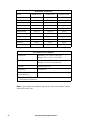
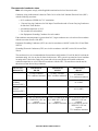
Installation
150/175kW Modular PDU
PDPM150G6F
PDPM150L6F
PDPM175G6H
Contents
Overview .......................................................................... 1
Important Safety Information . . . . . . . . . . . . . . . . . . . . . . . . . . . . . . . . 1
Disclaimer . . . . . . . . . . . . . . . . . . . . . . . . . . . . . . . . . . . . . . . . . . . . . . . 2
Please Note: . . . . . . . . . . . . . . . . . . . . . . . . . . . . . . . . . . . . . . . . . . . . 2
Additional Safety Information . . . . . . . . . . . . . . . . . . . . . . . . . . . . . . . 3
Before you begin . . . . . . . . . . . . . . . . . . . . . . . . . . . . . . . . . . . . . . . . 3
Operation and Adjustments . . . . . . . . . . . . . . . . . . . . . . . . . . . . . . . . 3
About This Manual .......................................................... 4
Related Documents. . . . . . . . . . . . . . . . . . . . . . . . . . . . . . . . . . . . . . . . 4
Product Related Information . . . . . . . . . . . . . . . . . . . . . . . . . . . . . . . . 4
User Comments. . . . . . . . . . . . . . . . . . . . . . . . . . . . . . . . . . . . . . . . . . . 4
Installation ....................................................................... 5
Electrical Safety . . . . . . . . . . . . . . . . . . . . . . . . . . . . . . . . . . . . . . . . . . 5
Inrow Installation. . . . . . . . . . . . . . . . . . . . . . . . . . . . . . . . . . . . . . . . . . 5
Perform Equipotential Bonding . . . . . . . . . . . . . . . . . . . . . . . . . . . . . . 6
Connect and Level Enclosures . . . . . . . . . . . . . . . . . . . . . . . . . . . . . . 6
Install Input Power Cables . . . . . . . . . . . . . . . . . . . . . . . . . . . . . . . . . . 7
Top entry installation . . . . . . . . . . . . . . . . . . . . . . . . . . . . . . . . . . . . . 7
Bottom entry installation . . . . . . . . . . . . . . . . . . . . . . . . . . . . . . . . . . 8
Install Subfeed Cables . . . . . . . . . . . . . . . . . . . . . . . . . . . . . . . . . . . . 10
Install User Input/Output Contacts . . . . . . . . . . . . . . . . . . . . . . . . . . 11
Install the Communication Cable . . . . . . . . . . . . . . . . . . . . . . . . . . . 13
150/175kW Modular PDU Installation
i
Power Distribution Modules (PDMs). . . . . . . . . . . . . . . . . . . . . . . . . 14
Installation . . . . . . . . . . . . . . . . . . . . . . . . . . . . . . . . . . . . . . . . . . . . . 14
Remove power distribution modules (PDMs) . . . . . . . . . . . . . . . . . 15
Install filler plates . . . . . . . . . . . . . . . . . . . . . . . . . . . . . . . . . . . . . . . 15
Options ........................................................................... 16
Shielding Troughs . . . . . . . . . . . . . . . . . . . . . . . . . . . . . . . . . . . . . . . 16
Seismic Stability Kit . . . . . . . . . . . . . . . . . . . . . . . . . . . . . . . . . . . . . . 17
Install rear anchoring brackets . . . . . . . . . . . . . . . . . . . . . . . . . . . . 17
Install front anchoring bracket . . . . . . . . . . . . . . . . . . . . . . . . . . . . . 18
Specifications ................................................................ 19
Recommended conductor sizes . . . . . . . . . . . . . . . . . . . . . . . . . . . 21
Regulatory Agency Approval ....................................... 22
ii
150/175kW Modular PDU Installation
Overview
Important Safety Information
Read the instructions carefully and look at the equipment to become familiar with the device before
trying to install, operate, service or maintain it. The following special messages may appear throughout
this manual or on the equipment to warn of potential hazards or to call attention to information that
clarifies or simplifies a procedure.
The addition of this symbol to a Danger or Warning safety label indicates that an electrical
hazard exists which will result in personal injury if the instructions are not followed.
This is the safety alert symbol. It is used to alert you to potential personal injury hazards.
Obey all safety messages that follow this symbol to avoid possible injury or death.
DANGER
DANGER indicates an imminently hazardous situation which, if not avoided, will result in death
or serious injury.
WARNING
WARNING indicates a potentially hazardous situation which, if not avoided, can result in death
or serious injury.
CAUTION
CAUTION indicates a potentially hazardous situation which, if not avoided, can result in minor or
moderate injury.
CAUTION
CAUTION, used without the safety alert symbol, indicates a potentially hazardous situation
which, if not avoided, can result in equipment damage.
NOTICE
NOTICE addresses practices not related to physical injury including certain environmental
hazards, potential damage or loss of data.
150/175kw Modular PDU Installation
1
Disclaimer
The information presented in this manual is not warranted by Schneider Electric to be authoritative, error
free, or complete. This publication is not meant to be a substitute for a detailed operational and site
specific development plan. Therefore, Schneider Electric assumes no liability for damages, violations of
codes, improper installation, or any other problems that could arise based on the use of this publication.
The information contained in this publication is provided as is and has been prepared solely for the
purpose of evaluating data center design and construction. This publication has been compiled in good
faith by Schneider Electric. However, no representation is made or warranty given, either express or
implied, as to the completeness or accuracy of the information this publication contains.
IN NO EVENT SHALL SCHNEIDER ELECTRIC, OR ANY AFFILIATE OR SUBSIDIARY
COMPANY OF SCHNEIDER ELECTRIC OR THEIR RESPECTIVE OFFICERS,
DIRECTORS, OR EMPLOYEES BE LIABLE FOR ANY DIRECT, INDIRECT,
CONSEQUENTIAL, PUNITIVE, SPECIAL, OR INCIDENTAL DAMAGES (INCLUDING,
WITHOUT LIMITATION, DAMAGES FOR LOSS OF BUSINESS, CONTRACT, REVENUE,
DATA, INFORMATION, OR BUSINESS INTERRUPTION) RESULTING FROM, ARISING
OUT OF, OR IN CONNECTION WITH THE USE OF, OR INABILITY TO USE THIS
PUBLICATION OR THE CONTENT, EVEN IF SCHNEIDER ELECTRIC HAS BEEN
EXPRESSLY ADVISED OF THE POSSIBILITY OF SUCH DAMAGES. SCHNEIDER
ELECTRIC RESERVES THE RIGHT TO MAKE CHANGES OR UPDATES WITH RESPECT
TO OR IN THE CONTENT OF THE PUBLICATION OR THE FORMAT THEREOF AT ANY
TIME WITHOUT NOTICE.
Copyright, intellectual, and all other proprietary rights in the content (including but not limited to
software, audio, video, text, and photographs) rests with Schneider Electric or its licensors. All rights in
the content not expressly granted herein are reserved. No rights of any kind are licensed or assigned or
shall otherwise pass to persons accessing this information.
This publication shall not be for resale in whole or in part.
Please Note:
Electrical equipment should be installed, operated, serviced, and maintained only by qualified personnel.
No responsibility is assumed by Schneider Electric for any consequences arising from the use of this
material.
A qualified person is one who has skills and knowledge related to the construction, installation, and
operation of electrical equipment and has received safety training to recognize and avoid the hazards
involved.
2
150/175kw Modular PDU Installation
Additional Safety Information
Before you begin
Verify that the system is free from all short circuits and grounds, except those grounds installed
according to local regulations (according to the National Electrical Code in the U.S.A., for instance). If
high-potential voltage testing is necessary, follow recommendations in equipment documentation to
prevent accidental equipment damage.
Before energizing equipment:
• Remove tools, meters, and debris from equipment.
• Close the equipment enclosure door.
• Remove ground from incoming power lines.
• Perform all start-up tests recommended by the manufacturer.
Operation and Adjustments
The following precautions are from the NEMA Standards Publication ICS 7.1-195 (English version
prevails):
• Regardless of the care exercised in the design and manufacture of equipment or in the selection
and ratings of components, there are hazards that can be encountered if such equipment is
improperly operated.
• It is sometimes possible to misadjust the equipment and thus produce unsatisfactory or unsafe
operation. Always use the manufacturer’s instructions as a guide for functional adjustments.
Personnel who have access to these adjustments should be familiar with the equipment
manufacturer's instructions and the machinery used with the electrical equipment.
• Only those operational adjustments actually required by the operator should be accessible to the
operator. Access to other controls should be restricted to prevent unauthorized changes in
operating characteristics.
WARNING
UNGUARDED MACHINERY HAZARD
• Do not use this product with equipment which does not have point-of-operation protection.
• Do not reach into equipment during operation.
Failure to follow these instructions can result in death, serious injury, or equipment
damage.
150/175kw Modular PDU Installation
3
About This Manual
This manual is intended for users of the specified APC equipment. It contains important safety warnings
and instructions, gives an introduction to the display interface and provides detailed information for
proper use of the equipment.
Related Documents
Download technical publications and other technical information or look for updates to your manual at
our website at www.apc.com.
Product Related Information
DANGER
HAZARD OF ELECTRIC SHOCK, EXPLOSION, OR ARC FLASH
Turn off all power supplying this equipment before working on the equipment.
Failure to follow these instructions will result in death or serious injury.
User Comments
We welcome your comments about this document. Contact www.apc.com/support.
4
150/175kw Modular PDU Installation
Installation
Electrical Safety
SAVE THESE INSTRUCTIONS!
This document contains important instructions that should be followed during installation of the 150/
175kW Modular Power Distribution Unit (PDU).
DANGER
HAZARD OF ELECTRIC SHOCK
• Only certified electricians are authorized to connect power to the PDU.
• The PDU must be installed in accordance with the National Electrical Code or
the Canadian Electrical Code and all applicable local codes.
• To prevent arcing when removing a Power Distribution Module (PDM) from
the panel, set all circuit breakers on that module to OFF (open).
Failure to follow these instructions can result in death or serious injury.
CAUTION
UNPROTECTED OUTPUTS
Remove cover plates from the unit before cutting holes for power cable access. Metal
shavings can cause serious equipment damage. A metal punch can be used to make
the holes in the plates.
Failure to follow these instructions can result in injury or equipment damage.
Inrow Installation
Maintain 36” hot aisle spacing.
pdx0849a
Hot Aisle
150/175kw Modular PDU Installation
5
Proper bonding is essential to create an equipotential plane
between service grounds and equipment during fault and
transient conditions.
Connect the two equipotential bonding conductors between
adjacent enclosures in the system. The bonding conductors are
pre-connected to the PDU. The M8 nuts and washers are
supplied in the accessory kit. Move the equipotential bonding
wires to fit your system configuration.
pdx0850a
Perform Equipotential Bonding
Connect and Level Enclosures
The equipment must be installed on a level floor. The
leveling feet will stabilize the enclosure, but will not account
for a badly sloped floor. If the PDU is on a raised-tile floor,
verify that it is properly aligned with the tiles.
2. Use a screwdriver to lower the four leveling
feet.
3. Use a 13/17 mm wrench to adjust the leveling
feet. Do not move the enclosure after the
leveling feet have been lowered.
pdx0852a
1. Align the enclosures.
pdx0851a
4. Turn the joining brackets and secure with a
screw to connect the enclosures.
6
150/175kw Modular PDU Installation
Install Input Power Cables
Top entry installation
1 Open the front door. Unlatch and swing the display
interface and bracket out towards the front door.
2 Loosen the captive screws and remove the top
safety panel.
3
1
2
pdx0830a
3 Loosen the captive screws and remove the front top
plate.
4 Remove the dedicated cover plate.
Drill holes in the plate for conduits
and re-install the plate with the
conduits installed.
4
5
For PDPM150G6F and
PDPM175G6H:
L1, L2, L3 - Torque: 31.1 Nm
(275 lb-in).
Ground - Torque: 5.6 Nm (50 lb-in).
6
5
L2
L1
L3
pdx0847a
5 Connect the input power cables.
For PDPM150L6F:
L1, L2, L3 - Torque: 28.3 Nm
(250 lb-in).
Ground - Torque: 5.6 Nm (50 lb-in).
Input Power
6 Grounding Electrode Conductor Torque: 62.2 Nm (550 lb-in).
150/175kw Modular PDU Installation
7
Bottom entry installation
Note: The sidecar is required for undefloor wiring into the PDU. The Sidecar does not contain a switch
or circuit breaker so a readily accessible disconnect device shall be incorporated external to the
equipment.
Sidecar Model
PDPM150SC
PDU Model
PDPM150G6F
PDPM150L6F
PDPM175G6H
PDPM100SC
1 Remove the dedicated cover plate. Drill holes
in the plate for conduits and re-install the
plate with the conduits installed. Route the
conductors (input conductors in single utility
systems or bypass conductors in dual utility
systems) through the bottom of the Side Car.
pdx0878a
2 Connect the input/bypass conductors to the
L1, L2, L3, EGC, and GEC terminals and
torque to specifications on label.
8
150/175kw Modular PDU Installation
3 Take the cables that are preinstalled in the Side Car and
route them through the left side into the PDU.
pdx0879a
To PDU
Power In
150/175kw Modular PDU Installation
9
Install Subfeed Cables
1 Open the rear doors.
1
2
pdx0823a
2 Remove the subfeed safety panel.
3 Loosen the four captive screws on each of two rear
dedicated cover plates. Drill holes in the plates for
conduits and re-install the plate with the conduits
installed.
3
pdx0829a
Note: Remove cover plates before cutting holes.
4 Connect the phase (L1, L2, L3) cables. Torque:
31.1 Nm (275 lb-in).
5 Connect the neutral (N) cable.
Torque: 62.2 Nm (550 lb-in).
G
N
6
6 Connect the ground (G) cable.
Torque: 5.6 Nm (50 lb-in).
4
7 Install the subfeed safety panel and close the rear
doors of the PDU.
Note: The same procedure is required to connect
Subfeed 1 and Subfeed 2 Circuit Breakers.
10
5
L1 L2 L3
150/175kw Modular PDU Installation
4
G
N
L1 L2 L3
6
Install User Input/Output Contacts
Note: Contact wires from external signaling, alarming, and sensing devices may be connected to the
interface board to allow the controller to monitor these devices and to also control outside devices
through the output contacts.
1 Open the front door and remove the top safety panel.
1
2
pdx0826a
2 Note the location of the interface board at the top of the
PDU.
3 Loosen the captive screws and remove the plate. Remove the
3/4-in (64-mm) knockout.
pdx0843a
3
4 Run the contact cables through the hole to the interface board.
pdx0837a
4
150/175kw Modular PDU Installation
11
5 Make connections to the labelled terminals on the interface board.
Note: Input Contacts are Normally open or Normally closed.
Available Output Contacts: DPDT, 1A@30VDC
AST0, AST1, AST2, ASTEN, AC/DC, +24V, and EPO CONTACT are reserved and not available.
Wiring: 12 AWG to 30 AWG is recommended.
12
150/175kw Modular PDU Installation
Install the Communication Cable
1 Connect the CAT-5 cable for
StruxureWare Central or your local area
network to the RJ45 connection coupling
on top of the PDU.
1
3 The other end of the internal cable is
plugged into the RJ-45 port on the panel
cover of the controller located at the
bottom of the unit.
150/175kw Modular PDU Installation
pdx0837a
2
pdx0838a
2 Inside the PDU enclosure, a second CAT5 cable is connected to the other side of
RJ45 coupling.
Front
3
13
Power Distribution Modules (PDMs)
Installation
Note: 1. Power distribution modules can be safely installed when the PDU is operational.
2. Install only APC-supplied PDMs with matching output voltage.
3. Install PDMs starting from the bottom of the panel to avoid cable congestion.
1 Open the front door of the PDU.
pdx0797a
1
2 Remove the filler plates. Press down on the filler plate clip to release
its locking mechanism.
Pull the filler plate directly toward you and along the slot on the left
side of the panel until it is free.
2
3 Install a module. Make sure all breakers on the PDM
being installed are in the OFF (open) position.
OFF position
3
ON position
4 Press the red button to release the latch on the PDM.
5 Pull open the latch.
4
5
14
150/175kw Modular PDU Installation
6 Slide the PDM into the panel using the top and bottom
guide tracks for that position. Make sure you slide the
PDM all the way into its position.
7 Close the latch. This will tighten electrical contacts in
the PDM against the busbar.
6
6
6
pdx0298b
8 Feed cable from the PDM through the slot in the roof
of the PDU.
Note: Leave a minimum of 7 inches (178 mm) of
slack in the cable behind the module. The slack is
useful in case the module is ever removed or replaced.
10 to 20 inches (254 to 508 mm) is recommended but
space restrictions in the PDU and cable diameter size
will cause the amount of slack to necessarily vary.
Note: When installing PDMs near the top of the
panel, perform step 8 before steps 6 and 7 to avoid
cable congestion between the panel and the slot.
6
9 Set all breakers on the newly installed PDM to the ON
(closed) position.
Close the front door of the PDU.
Connect the PDM cable to the appropriate rack-mount
PDU or other equipment
Remove power distribution modules (PDMs)
Reverse the installation procedure to remove a PDM
(making sure all breakers on the module are OFF).
pdx0840a
7
pdx0839a
8
OFF position
9
ON position
Install filler plates
Install APC filler plates (part number 870-14628) to properly cover 3-pole panel positions that are not
occupied by a power distribution module.
j
150/175kw Modular PDU Installation
15
Options
Shielding Troughs
pdx0844a
1
1 Snap an APC-provided trough into slots on the roof of the PDU. The tabs at the base of the trough must
fit securely into the slots.
Note: Properly align the PDU trough with troughs installed on top of the enclosures located adjacent to
the PDU.
pdx0845a
2
2 Feed PDM cables through the roof of the PDU and into the trough system for connection with the
appropriate rack-mount PDUs.
16
150/175kw Modular PDU Installation
Seismic Stability Kit
Install rear anchoring brackets
1 Secure the floor anchoring bracket to the
floor using floor anchoring bolts (not
supplied). Use M12 strength class 8.8 or
1/2 inch, grade 5 steel bolts.
1
2 Secure the back of the other half of the bracket
assembly to the back of the unit.
2
3 Push the unit back to slide the bracket on the unit
under the bracket bolted to the floor.
3
150/175kw Modular PDU Installation
17
Install front anchoring bracket
1 Secure the front anchoring bracket to the
enclosure.
1
2 Secure the front anchoring bracket to the floor
using floor anchoring bolts (not supplied). Use M12
strength class 8.8 or 1/2 inch, grade 5 steel bolts.
2
18
150/175kw Modular PDU Installation
Specifications
AC Input
Model
PDPM150G6F
PDPM150L6F
PDPM175G6H
Nominal voltage
480V, 3W +G
600V, 3W +G
480V, 3W + G
Frequency
60 Hz
60 Hz
60 Hz
Maximum
continuous
current
180 A
150 A
214 A
Nominal current
178 A
141 A
214 A
Recommended current rating of input circuit breakers
Mains Input1 (A)
225
200
300
2000
1500
2100
Inrush currents
Inrush Current2
Standard circuit breakers are rated to carry 80% of their current rating
continuously.
2 The supply overcurrent protective device must be able to handle the listed
transformer inrush currents.
1
AC Output
PDPM150G6F
PDPM150L6F
PDPM175G6H
208Y/120V,
3W + N + G
208Y/120V,
3W + N + G
415Y/240V,
3W + N + G
400 A
400 A
243 A
144 kW @ 208V 3
PH
144 kW @ 208V 3
PH
175kW @ 415V 3 PH
208/120V, 3-pole
modules
208/120V, 3-pole
modules
415/240V, 3-pole
modules
Power distribution poles
available
72
72
72
Maximum number of PDMs
24
24
24
Model
Nominal voltage
Maximum continuous current
Full load rating
Power distribution module
(PDM)
150/175kw Modular PDU Installation
19
Distribution Transformer
PDPM150G6F
PDPM150L6F
PDPM175G6H
Size
150 kVA
150 kVA
175 kVA
Type
Delta/Wye
Delta/Wye
Delta/Wye
Input voltage
480V
600V
480V
Input current
180 A
150 A
214 A
Output voltage
208Y/120V
208Y/120V
415Y/240V
Output current
399.72 A
399.72 A
243.47
180 NC
180 NC
180 NC
455 kg (1003 lb)
500 kg (1102 lb)
560 kg (1235 lb)
Efficiency
98.2% min.
98.2% min.
98.5% min.
Frequency
60 Hz
60 Hz
60 Hz
< 55 db @ 1 m
< 55 db @ 1 m
< 55 db @ 1 m
Model
Thermal sensing
Weight
Noise
Environment and Compliance
Temperature
Operating: -5 to +40°C (23 to 104°F)
Storage: -25 to +65°C (-13 to 149°F)
Humidity
Operating: 0 to 95%, non-condensing
Storage: 0 to 95%, non-condensing
Elevation
3000 m (9,842.5 ft)
Certification
UL and cUL
Conditional Short-Circuit
Current Rating (ICC)
10 kA*
* The Conditional Short-Circuit Current Rating was not evaluated by
Underwriters Laboratories.
Note: Circuit breakers and conductor ampacity are derated in accordance with the
National Electrical Code.
20
150/175kw Modular PDU Installation
Recommended conductor sizes
Note: All wiring must comply with all applicable national and or local electrical codes.
Conductor sizing in this manual is based on Table 310-16 of the 2011 National Electrical Code (NEC)
with the following assertions:
• 90°C conductors (THHN) for 75°C termination
• 3 Current Carrying Conductors for Unit Input Circuit Breaker and 4 Current Carrying Conductors
for Subfeed Circuit Breaker
• An ambient temperature of 30°C
• Two conduits for each subfeed
• One Equipment Grounding Conductor for each conduit
If the ambient room temperature is greater than 30°C, larger conductors are to be selected in accordance
with the correction factors of the NEC.
Equipment Grounding Conductors (EGC) are sized in accordance with NEC Article 250-122 and Table
250-122.
Grounding Electrode Conductors (GEC) are sized in accordance with NEC Article 250-66 and Table
250-66.
The conductor sizes are recommendations for maximum configurations. Even if the load is less than the
maximum rating, it is wise to plan for future load increases. If the system is operated at a lower load than
its rating and it is desired to supply the system with a lower rated breaker and smaller conductors,
conductor ampacities are to be selected in accordance with the NEC. The transformer inrush must be
taken into account when sizing conductors.
Table for 40°C
ambient/4CCC
PDPM150G6F
480:208
PDPM150L6F
600:208
PDPM175G6H
480:415
Cu only: 250kcmil
75°C conductor minimum
Cu only: 3/0 AWG
90°C conductor minimum
Cu: 350kcmil
Al: 500kcmil
75°C conductor minimum
Equipment
Grounding
Conductor (EGC)
Cu: 4 AWG
Cu: 6 AWG
Cu: 4 AWG
Al: 2 AWG
Grounding
Electrode
Conductor (GEC)
Cu: 2 AWG
Cu: 2 AWG
Cu: 2 AWG
Al: 1/0 AWG
Mains Input Φ
Output
Subfeed Output
Supplied with Power Distribution Modules
Cu only: (2) 300kcmil Φ and Cu only: (2) 300kcmil Φ and Cu: (2) 2/0 AWG Φ and N, 4
N, 3 AWG EGC, GEC not N, 3 AWG EGC, GEC not
AWG EGC, GEC not
required.
required.
required.
90°C conductor minimum
90°C conductor minimum Al: (2) 4/0 AWG Φ and N, 2
AWG EGC, GEC not
required.
75°C conductor minimum
150/175kw Modular PDU Installation
21
Table for 30°C
ambient/4CCC
PDPM150G6F
480:208
PDPM150L6F
600:208
PDPM175G6H
480:415
Mains Input Φ
Cu: 4/0 AWG
A1: 300kcmil
75°C conductor minimum
Cu only: 3/0 AWG
90°C conductor minimum
Cu: 300kcmil
Al: 400kcmil
75°C conductor minimum
Equipment
Grounding Conductor
(EGC)
Cu: 4 AWG
A1: 2 AWG
Cu: 6 AWG
Cu: 4 AWG
Al: 2 AWG
Grounding Electrode
Conductor (GEC)
Cu: 2 AWG
A1: 1/0 AWG
Cu: 2 AWG
Cu: 2 AWG
Al: 1/0 AWG
Output
Supplied with Power Distribution Modules
Subfeed Output
Cu: (2) 250kcmil Φ and N, Cu: (2) 250kcmil Φ and N, Cu: (2) 2/0 AWG Φ and N,
3 AWG EGC, GEC not
3 AWG EGC, GEC not
4 AWG EGC, GEC not
required.
required.
required.
Al: (2) 350 kcmil Φ and N, Al: (2) 350 kcmil Φ and N, Al: (2) 3/0 AWG Φ and N,
1 AWG EGC, GEC not
1 AWG EGC, GEC not
2 AWG EGC, GEC not
required.
required.
required.
90°C conductor minimum 90°C conductor minimum 75°C conductor minimum
Φ = phase, N = neutral
(2) = two conductors per phase and neutral (when neutral is required)
Subfeed is required to have two conductors per phase & N for full output due to limited wire bend space
Cu= Copper conductors, Al= Aluminum conductors
CCC = Current Carrying Conductor
Regulatory Agency Approval
This equipment has been tested and found to comply with the limits for a Class A digital device,
pursuant to Part 15 of the FCC and ICES-003 Rules. These limits are designed to provide reasonable
protection against harmful interference when the equipment is operated in a commercial environment.
This equipment generates, uses, and can radiate radio frequency energy and, if not installed and used in
accordance with the Installation Guide, may cause harmful interference to radio communications.
Operation of this equipment in a residential area is likely to cause harmful interference, in which case the
user will be required to correct the interference at his own expense.
22
150/175kw Modular PDU Installation
Radio Frequency Interference
Note: Changes or modifications to this unit not expressly approved by the party responsible for
compliance could void the user’s authority to operate this equipment.
USA—FCC
This equipment has been tested and found to comply with the limits for a Class A digital device,
pursuant to part 15 of the FCC Rules. These limits are designed to provide reasonable protection
against harmful interference when the equipment is operated in a commercial environment. This
equipment generates, uses, and can radiate radio frequency energy and, if not installed and used in
accordance with this user manual, may cause harmful interference to radio communications. Operation
of this equipment in a residential area is likely to cause harmful interference. The user will bear sole
responsibility for correcting such interference.
Canada—ICES
This Class A digital apparatus complies with Canadian ICES-003.
Cet appareil numérique de la classe A est conforme à la norme NMB-003 du Canada.
APC Worldwide Customer Support
Customer support for this or any other APC product is available at no charge in any of the following ways:
• Visit the APC Web site to access documents in the APC Knowledge Base and to submit customer
support requests.
– www.apc.com (Corporate Headquarters)
Connect to localized APC Web sites for specific countries, each of which provides customer support
information.
– www.apc.com/support/
Global support searching APC Knowledge Base and using e-support.
• Contact the APC Customer Support Center by telephone or e-mail.
– Local, country-specific centers: go to www.apc.com/support/contact for contact information.
For information on how to obtain local customer support, contact the APC representative or other distributors
from whom you purchased your APC product.
© 2012 APC by Schneider Electric. APC, and the APC logo are owned by Schneider Electric Industries
S.A.S., American Power Conversion Corporation, or their affiliated companies. All other trademarks are
property of their respective owners.
990-4384
5/2012