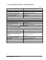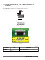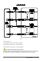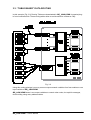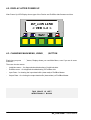
1
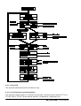
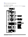
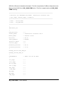
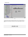
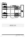
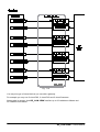
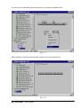
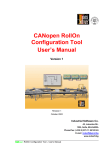
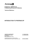
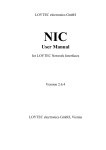
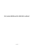
DP_LON LINK
User’s Manual
Pre-release
Revision May 2003
Industrial Software Ltd.
45, Lokorska Str.
1225, Sofia, BULGARIA
Phone/Fax: (+359 2) 975 11 80/1/2/3/4
E-mail: [email protected]
www.indsoft.bg
DP_LON LINK – User’s Manual
CONTENTS
CHAPTER 1. DP_LON LINK PROFIBUS TO LONWORKS GATEWAY
SPECIFICATIONS
1.1.
DP_LON LINK TECHNICAL CHARACTERISTICS ................................................1-1
1.2.
DP_LON LINK GENERAL DESCRIPTION ...............................................................1-
1.3.
DP_LON LINK DIMENSIONS....................................................................................1-
CHAPTER 2. DP_LON LINK CONNECTIONS
2.1.
DP_LON LINK POWER SUPPLY ...........................................................................2-1
2.2.
CONNECTION OF THE DP_LON LINK TO PROFIBUS DP NETWORK.................2-
2.3.
CONNECTION OF THE DP_LON LINK TO A LONWORKS NETWORK ................2-
CHAPTER 3. PRINCIPALS OF DATA ROUTING
3.1.
DP SIDE BUFFER NAMING........................................................................................3-1
3.2.
“HARD” DATA ROUTING.............................................................................................3-
3.3.
“TABLE BASED” DATA ROUTING .............................................................................3-
CHAPTER 4. KEYBOARD AND LCD DISPLAY
4.1.
4.1.1.
KEYBOARD AND LCD BASICS.................................................................................4-1
Button..................................................................................................................4-
4.1.2.
And
Buttons .....................................................................................................4-
4.1.3.
And
Buttons......................................................................................................4-
4.2.
DISPLAY AFTER POWER UP ......................................................................................4-
4.3.
CHANGING MAIN MENU, USING
4.4.
USING
4.4.1
LonWorks Menu & Submenus .......................................................................................4-
4.4.1.1.
Neuron ID ........................................................................................................................4-
4.4.1.2.
Ver/Transceiver type/Subnet/Node .....................................................................................4-
AND
BUTTON .....................................................4-
TO CHANGE SUBMENU ...........................................................4-
DP_LON LINK – User’s Manual
i
4.4.2.
ProfiBus Menu & Submenus ..........................................................................................4-
4.4.2.1.
ProfiBus Address Submenu ...............................................................................................4-
4.4.2.2.
DP Control/Baudrate Submenu ..........................................................................................4-
4.4.3.
Input Data Menu ............................................................................................................4-
4.4.4.
Output Data Menu..........................................................................................................4-
4.5.
CONFIGURING PROFIBUS SIDE PARAMETERS ......................................................4-
4.5.1.
Baudrate ........................................................................................................................4-
4.5.2.
DP Address Setting........................................................................................................4-
4.5.2.1.
DP Address Setting via LonWorks Configuration Tool ..........................................................4-
4.5.2.2.
DP Address Setting via Keyboard.......................................................................................4-
CHAPTER 5. GSD FILE
CHAPTER 6. PREPARING SIEMENS STEP7 DEVELOPMENT
ENVIRONMENT FOR USING DP_LON LINK
CHAPTER 7. USING DP_LON LINK IN CONVEYOR CONTROL
SYSTEMS
ii
DP_LON LINK – User’s Manual
CHAPTER 1
DP_LON LINK PROFIBUS
TO LONWORKS GATEWAY
SPECIFICATIONS
1.1.
DP_LON LINK TECHNICAL CHARACTERISTICS
1.2.
DP_LON LINK GENERAL DESCRIPTION
1.3.
DP_LON LINK DIMENSIONS
DP_LON LINK – User’s Manual
1.1. DP_LON LINK TECHNICAL CHARACTERISTICS
Table1.1
PARAMETER
RANGE (SPEC’S) DESCRIPTION
Power Supply Voltage
-
Nominal power supply voltage
24 V DC (rectified, filtered, with maximum
ripples 300 mV peak-to-peak)
-
Power supply voltage range
18 to 30 V DC
-
Current consumption
150mA max.
-
Connector
Terminal 1.5 mm2
ProfiBus DP Interface
-
ProfiBus DP Slave functionality
-
Internally powered, “flying ground”, galvanically isolated
-
Max. baudrate supported
12Mbits/sec.
-
Connector
9 way, sub D, plug connector
LonWorks Interface
-
FTT-10 or TPT/XF1250 interface
Environment specifications
Protection
IP20
Nominal temperature range
-20 C to 65 C
Temperature: -20 C to 85 C
Conditions for transportation and
storage
Humidity: up to 90% RH
FRAGILE!
Electromagnetic compatibility
IEC 1131 – 2, IEC 801 – Level 2
Dimensions
153mm x 125mm x 60mm
Mounting
DIN Rail
Weight
about 250g
DP_LON LINK – User’s Manual
1-1
1.2. DP_LON LINK GENERAL DESCRIPTION
The front view of the DP_LON LINK is shown in Fig. 1.1.
Fig. 1.1
Each DP_LON LINK provides following features:
Connector for 24V DC power supply.
Power LED indicator.
Connector for LonWorks interface.
LonWorks service pin button
LonWorks service LED
LonWorks side “RUN” LED
Connector for ProfiBus DP interface.
DP transmit LED
DP receive LED
DP Exchange LED (Master Found)
1-2
DP_LON LINK – User’s Manual
LCD Display for data monitoring/diagnostics/DP Address configuration.
5 buttons for LCD menu/submenu select, DP address configuration and ENTER.
CANopen connector & Led – not applicable for DP_LON LINK.
Modbus connector & Led - not applicable for DP_LON LINK.
1.3. DP_LON LINK DIMENSIONS
DP_LON LINK is assembled on a DIN rail.
DP_LON LINK has the following dimensions:
Width – 153 mm
Height – 125 mm
Thickness (including connectors) – 60 mm
DP_LON LINK – User’s Manual
1-3
CHAPTER 2
DP_LON LINK
CONNECTIONS
2.1.
DP_LON LINK POWER SUPPLY
2.2.
CONNECTION OF THE DP_LON LINK TO PROFIBUS DP NETWORK
2.3.
CONNECTION OF THE DP_LON LINK TO A LONWORKS NETWORK
DP_LON LINK – User’s Manual
2.1. DP_LON LINK POWER SUPPLY
The DP_LON LINK is powered by 24 V DC (Fig. 2.1), whereas the power supply voltage is
subject to the following requirements:
-
rectified;
-
filtered;
-
max. ripples 300 mV peak-to-peak
Fig. 2.1
The power supply of the DP_LON LINK is galvanically isolated from the power supply of the
processor, LonWorks and ProfiBus.
Table 2.1
Connector
Type
Description
24 V
terminal 1.5 mm2
1,2 - DP_LON LINK power supply, polarity
insensitive
Table 2.2
LED
POWER
Type
RED
DP_LON LINK – User’s Manual
Description
LED ON shows that the power supply voltage is
connected; LED OFF shows the absence of
power supply voltage
2-1
2.2. CONNECTION OF THE DP_LON LINK TO PROFIBUS DP
NETWORK
DP_LON LINK is connected to DP Network via 9-way connector.
Fig. 2.2
Table 2.3
Connector
ProfiBus
2-2
Type
9 way, sub D, plug
connector
Description
ProfiBus communication
DP_LON LINK – User’s Manual
Table 2.4
LED
Type
Description
RxD
GREEN
ProfiBus receive
TxD
RED
ProfiBus transmit
ProfiBus exchange
Exchange
BLUE
LED ON - Master found and normal exchange in
progress
LED OFF – Master not found
POW
RED
LED ON – ProfiBus isolated power supply OK
2.3. CONNECTION OF THE DP_LON LINK TO A LONWORKS
NETWORK
DP_LON LINK is connected to a LonWorks network by means of three-wire line (Fig. 2.3).
The two outer terminals are connected to FTT-10 or TPT/XF-1250 LonWorks channel. The midterminal must be connected to workshop (facilities) earth.
Attention: Failing to connect mid-terminal to earth will cause networking problems
in LonWorks TPT/XF-1250 channel and bad electromagnetic immunity of the device.
Fig. 2.3
DP_LON LINK – User’s Manual
2-3
Table 2.5
Connector
Type
Description
LonWorks
2
terminal 1.5 mm
1, 3 – LonWorks FTT-10 or TPT/XF – 1250
network, polarity insensitive
2 - EARTH
Table 2.6
LED
Type
Description
Service
RED
Standard LonWorks service LED
RXD
GREEN
Data received from LonWorks
2-4
DP_LON LINK – User’s Manual
CHAPTER 3
PRINCIPALS OF DATA
ROUTING
3.1.
DP SIDE BUFFER NAMING
3.2.
“HARD” DATA ROUTING
3.3.
“TABLE BASED” DATA ROUTING
DP_LON LINK – User’s Manual
3.1. DP SIDE BUFFER NAMING
Names of buffers on ProfiBus DP side are named as they are viewed from Master
side, i.e. “Input Buffer” is the Buffer read from Master and “Output Buffer ”is the Buffer
written from Master!
Both LonWorks and ProfiBus DP are data oriented protocols, i.e. data is exchanged between
nodes, not commands.
So the main task of DP_LON LINK is to transfer data from LonWorks to ProfiBus side and
vice versa.
Two principals of data routing are supported by DP_LON LINK:
3.2. “HARD” DATA ROUTING
In “Hard” routing scenario an array of 16 LonWorks byte size input variables is transferred to
ProfiBus Input buffer, and 15 bytes of the ProfiBus Output buffer are transferred to 15 LonWorks
byte size output variables.
THIS SPACE IS LEFT
INTENTIONALLY BLANK
DP_LON LINK – User’s Manual
3-1
Fig. 3.1
The routing is fixed:
nvi Disc Sts[0] is moved in byte 0 of DP Input Buffer
nvi Disc Sts[1] is moved in byte 1 of DP Input Buffer
………………..
nvi Disc Sts[15] is moved in byte 15 of DP Input Buffer
This routing scenario has a major restriction:
LonWorks chip has only 15 address tables. This means that you can read no more than
16 variables from LonWorks in DP Master and control no more than 15 variables.
3-2
DP_LON LINK – User’s Manual
3.3. “TABLE BASED” DATA ROUTING
In this scenario (Fig. 3.2) Routing Tables are downloaded in DP_LON LINK via special plugin from LonWorks side. These routing tables allow to avoid restriction of Neuron Chip.
Fig. 3.2
Using this routing principal, you may connect output network variables from few modules to one
input variable of DP_LON LINK.
DP_LON LINK doesn’t use output variables to control other nodes, but explicit messages,
thus avoiding using many address tables.
DP_LON LINK – User’s Manual
3-3
CHAPTER 4
KEYBOARD AND
LCD DISPLAY
4.1.
4.1.1.
KEYBOARD AND LCD BASICS
Button
4.1.2.
And
Buttons
4.1.3.
And
Buttons
4.2.
DISPLAY AFTER POWER UP
4.3.
CHANGING MAIN MENU, USING
4.4.
USING
4.4.1
LonWorks Menu & Submenus
4.4.1.1.
Neuron ID
4.4.1.2.
Ver/Transceiver type/Subnet/Node
4.4.2.
ProfiBus Menu & Submenus
4.4.2.1.
ProfiBus Address Submenu
AND
BUTTON
TO CHANGE SUBMENU
DP_LON LINK – User’s Manual
4.4.2.2.
DP Control/Baudrate Submenu
4.4.3.
Input Data Menu
4.4.4.
Output Data Menu
4.5.
CONFIGURING PROFIBUS SIDE PARAMETERS
4.5.1.
Baudrate
4.5.2.
DP Address Setting
4.5.2.1.
DP Address Setting via LonWorks Configuration Tool
4.5.2.2.
DP Address Setting via Keyboard
DP_LON LINK – User’s Manual
4.1. KEYBOARD AND LCD BASICS
Keyboard and LCD are used for local monitoring/diagnostic/DP address selection.
There are 5 buttons on DP_LON LINK keyboard.
Fig. 4.1
4.1.1.
Button
Menu button is used to browse throw four main menus of DP_LON LINK:
-
LonWorks Menu
-
ProfiBus Menu
-
Input Data (ProfiBus Side)
-
Output Data (ProfiBus Side)
4.1.2.
And
Buttons
These buttons are used to browse in submenus, inside selected main menu.
4.1.3.
And
Buttons
These buttons are used to change ProfiBus DP address of the device.
DP_LON LINK – User’s Manual
4-1
4.2. DISPLAY AFTER POWER UP
After Power Up LCD Display shows type of the Device and ProfiBus side firmware revision.
DP_LON LINK
< VER 1.2 >
4.3. CHANGING MAIN MENU, USING
Each time you press
submenu.
BUTTON
button, Display shows you next Main Menu, even if you are in some
There are 4 main menus:
-
LonWorks menu – for diagnostic/troubleshooting of LonWorks side
-
ProfiBus menu – for diagnostic/troubleshooting of ProfiBus side
-
Input Data – for viewing the input data buffer (data read) of ProfiBus Master
-
Output Data – for viewing the output data buffer (data written) of ProfiBus Master
THIS SPACE IS LEFT
INTENTIONALLY BLANK
4-2
DP_LON LINK – User’s Manual
4.4. USING
AND
TO CHANGE SUBMENU
When you are in some main menu, you may browse in it’s submenus, pressing
buttons.
or
4.4.1. LonWorks Menu & Submenus
Press and release
button, until you see “LonWorks Menu” on LCD Display. Then Press
or
buttons to go in it’s submenus:
DP_LON LINK – User’s Manual
4-3
4.4.1.1. Neuron ID
This submenu shows Neuron ID of the Neuron chip
4.4.1.2. Ver/Transceiver type/Subnet/Node
This submenu shows revision of LonWorks side firmware, transceiver type installed (FTT-10 or
TPT/XF-1250 or TPT/XF-78) and subnet /node ID/, configured by configuration tool.
4-4
DP_LON LINK – User’s Manual
All other submenus are for maintenance only.
4.4.2. ProfiBus Menu & Submenus
Press and release
button, until you see “ProfiBus Menu” on LCD. Then use
buttons to browse in submenus:
DP_LON LINK – User’s Manual
or
4-5
4.4.2.1. ProfiBus Address Submenu
DP address (1-125) of the device is displayed.
4.4.2.2. DP Control/Baudrate Submenu
This submenu shows DP Baud search status.
-
Baud Search – Gateway is waiting for valid messages on ProfiBus DP network.
-
Baud Control – Gateway is found valid packets and has detected baudrate, but master
doesn’t communicates with it.
-
*DP Control – normal operation. Gateway has found valid packets and is configured by
Master.
All others submenus are for troubleshooting only.
4.4.3. Input Data Menu
Press and release
button, until you see “Input Data” on the LCD display. Then use
buttons to browse values in Input Buffer (buffer, which is read by Master).
or
4.4.4. Output Data Menu
Press and release
button, until you see “Output Data” on the LCD display. Then use
buttons to browse values in Output Buffer (buffer, which is written by Master).
or
4.5. CONFIGURING PROFIBUS SIDE PARAMETERS
4.5.1. Baudrate
DP_LON LINK Gateway has “Auto baud rate” functionality, so programming of the baudrate
is not required.
4.5.2. DP Address Setting
4.5.2.1. DP Address Setting via LonWorks Configuration Tool
You may select device’s DP Address in the plug-in for DP_LON LINK.
4.5.2.2. DP Address Setting via Keyboard
button, until you see “ProfiBus Menu” on the LCD display.
-
Press
-
Press
-
button to change the number on the second row of the LCD display. Note that
Press
button only increments the address and has auto acceleration functionality (i.e. if you
keep pressed the button, the speed of incrementing will increase).
-
When you reach the desired address, press
4-6
or
buttons until you see “ProfiBus Address” on the LCD display.
button to enter the new address FLASH.
DP_LON LINK – User’s Manual
CHAPTER 5
GSD FILE
DP_LON LINK – User’s Manual
GSD file is Electronic datasheet description. This file is imported by ProfiBus configuration tools.
Bellow is listed GSD file for DP_LON LINK device. This file is supplied with each DP_LON
LINK Gateway.
;=============================================================
; GSD-File for PROFIBUS-DP-SLAVE
Industrial Software LTD.
; Sync_supp, Freeze_supp, 12 MBit/s
;=============================================================
; Date
: 30.05.2003
; File
: DP_LON.GSD
;=============================================================
;
#Profibus_DP
;
GSD_Revision
= 1
Vendor_Name
= "Industrial Software LTD."
Model_Name
= "DP/Lon Link"
Revision
= "A.1"
Ident_Number
= 0x06F1
Protocol_Ident
= 0
Station_Type
= 0
Hardware_Release
= "H.1"
Software_Release
= "1.2"
;
Bitmap_Device="DP_LON_N"
Bitmap_SF="DP_LON_S"
;
OrderNumber
= "6ES7 222 AS DP LON"
;
9.6_supp
= 1
19.2_supp
= 1
93.75_supp
= 1
187.5_supp
= 1
500_supp
= 1
1.5M_supp
= 1
3M_supp
= 1
6M_supp
= 1
12M_supp
= 1
;
DP_LON LINK – User’s Manual
5-1
MaxTsdr_9.6
= 60
MaxTsdr_19.2
= 60
MaxTsdr_93.75
= 60
MaxTsdr_187.5
= 60
MaxTsdr_500
= 100
MaxTsdr_1.5M
= 150
MaxTsdr_3M
= 250
MaxTsdr_6M
= 450
MaxTsdr_12M
= 800
;
Redundancy
= 0
Repeater_Ctrl_Sig
= 0
Implementation_type = "SPC3"
; SPC3 ASIC used.
;
Freeze_Mode_supp
= 1
Sync_Mode_supp
= 1
Auto_Baud_supp
= 1
Set_Slave_Add_supp
= 0
User_Prm_Data_Len
= 0
Min_Slave_Intervall = 100
Modular_Station
= 1
Max_Module
= 8
Max_Input_Len
= 128
Max_Output_Len
= 128
Max_Data_Len
= 256
Slave_Family
= 9
Max_Diag_Data_Len
= 6
;
Module
= "2 Byte Out, 2 Byte In" 0x11,0x21
1
EndModule
;
Module
= "4 Byte Out, 4 Byte In" 0x13,0x23
2
EndModule
;
Module
= "8 Byte Out, 8 Byte In" 0x17,0x27
3
EndModule
5-2
DP_LON LINK – User’s Manual
;
Module
= "16 Byte Out, 16 Byte In" 0x1F,0x2F
4
EndModule
;
Module
= "32 Byte Out, 32 Byte In" 0x1F,0x1F,0x2F,0x2F
5
EndModule
;
DP_LON LINK – User’s Manual
5-3
CHAPTER 6
PREPARING SIEMENS
STEP7 DEVELOPMENT
ENVIRONMENT FOR USING
DP_LON LINK
DP_LON LINK – User’s Manual
In order to use DP_LON LINK with STEP7 software and Siemens PLC’s follow the steps below:
-
Copy files on Fig. 6.1 on your PC
Fig. 6.1
-
Run STEP7 software
-
Enter “hardware” screen
-
Import dp_lon.gsd file (Fig. 6.2 and Fig. 6.3)
Fig. 6.2
DP_LON LINK – User’s Manual
6-1
Fig. 6.3
Now you can add DP_LON LINK in your projects.
Fig. 6.4
6-2
DP_LON LINK – User’s Manual
CHAPTER 7
USING DP_LON LINK IN
CONVEYOR CONTROL
SYSTEMS
DP_LON LINK – User’s Manual
Using DP_LON LINK with RollOn configuration tool is simple and easy.
First add a DP_LON LINK device in your project.
Fig. 7.1
THIS SPACE IS LEFT
INTENTIONALLY BLANK
DP_LON LINK – User’s Manual
7-1
Each DP_LON LINK provides 4 types of virtual devices to user:
Fig. 7.2
THIS SPACE IS LEFT
INTENTIONALLY BLANK
7-2
DP_LON LINK – User’s Manual
-
Virtual run/status pair
Fig. 7.3
This virtual device sends nvoSensOut variable in one byte of the Master’s Input buffer and uses
1 byte of Master’s Output buffer to control nviSensIn variable of the same zone. This virtual
device replaces DIO functionality.
Fig. 7.4
DP_LON LINK – User’s Manual
7-3
-
Virtual accumulate/status pair
Fig. 7.5
This virtual device sends nvoSensOut variable in one byte of the Master’s Input buffer and uses
1 byte of Master’s Output buffer to control nviAccJog variable of the same zone. This virtual
device replaces “Scale” device functionality.
Fig. 7.6
7-4
DP_LON LINK – User’s Manual
-
Virtual scanner
Fig. 7.7
This virtual device uses same connectivity as “Scanner” device. It connects nvoSensOut
variables for zones A and B of an LRCM and sends them in 2 bytes of Master’s Input buffer. It
also connects 2 bytes of Master’s Output buffer to control nviAccJog variables of A and B
zones.
THIS SPACE IS LEFT
INTENTIONALLY BLANK
DP_LON LINK – User’s Manual
7-5
Fig. 7.8
THIS SPACE IS LEFT
INTENTIONALLY BLANK
7-6
DP_LON LINK – User’s Manual
-
Virtual RIO
Fig. 7.9
This virtual device reads and controls 4 input/4 output variables of KID Neuro the same way as
RIO module does.
THIS SPACE IS LEFT
INTENTIONALLY BLANK
DP_LON LINK – User’s Manual
7-7
Fig. 7.10
You may mix type of virtual devices you use with a gateway.
For example you may use 5 virtual RIO, 2 virtual DIO and 5 virtual Scanners.
Always take in account, that DP_LON LINK transfers up to 32 variables to Master and
32 variables from Master.
7-8
DP_LON LINK – User’s Manual
You may remove individually each virtual device or remove the Gateway at all.
Fig. 7.11
When Gateway is removed all associated virtual devices are removed also.
Fig. 7.12
DP_LON LINK – User’s Manual
7-9
DP_LON LINK – User’s Manual