1
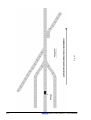
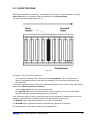
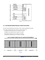
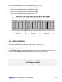
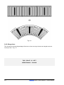
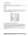
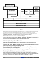
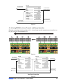
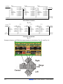
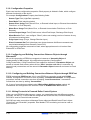
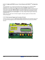
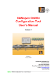
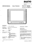
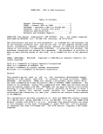
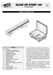
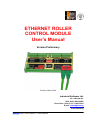
ETHERNET ROLLER
CONTROL MODULE
User’s Manual
Version Preliminary
Revision March 2004
Industrial Software Ltd.
45, Lokorska Str.
1225, Sofia, BULGARIA
Phone/Fax: (+359 2) 975 11 80/1/2/3/4
E-mail: [email protected]
H
H
www.indsoft.bg
Ethernet Roller Control Module – User’s Manual
CONTENTS
CAPTER 1. DEFINITIONS, SAFETY AND OPERATING INSTRUCTIONS
1.1.
EXPLANATION OF SYMBOLS............................................................................ 1-1
1.2.
DEFINITIONS AND ABBREVIATIONS ............................................................... 1-1
1.3.
NUMERICAL DATA ............................................................................................... 1-2
1.4.
SAFETY AND OPERATING INSTRUCTIONS ................................................... 1-2
CHAPTER 2. GENERAL INFORMATION
2.1.
POWERED ROLLER CONVEYOR CONFIGURATION.................................... 2-1
2.2.
CONVEYOR ZONE ................................................................................................ 2-3
2.3.
UPSTREAM/DOWNSTREAM CONVEYOR ZONES......................................... 2-4
2.4.
CONVEYOR AREAS ............................................................................................. 2-5
2.4.1.
Standard (Linear) Area ............................................................................................ 2-5
2.4.2.
Merge Area ............................................................................................................... 2-6
2.4.3.
Divert Area................................................................................................................ 2-8
2.5.
CONVEYOR MODES OF OPERATION .............................................................. 2-9
2.5.1.
Regular Mode of Operation..................................................................................... 2-9
2.5.2.
Accumulation ........................................................................................................... 2-9
2.5.3.
Jog ............................................................................................................................ 2-9
2.5.4.
Train .......................................................................................................................... 2-9
2.5.5.
Singulation ............................................................................................................... 2-9
2.5.6.
Purge......................................................................................................................... 2-9
2.6.
"CONTROL MODULE - TO - CONVEYOR" INTERFACE ............................... 2-9
2.6.1.
Brushless Powered Roller Interface .................................................................... 2-10
2.6.2.
Photosensor Interface........................................................................................... 2-11
2.7.
ERCM ZONES....................................................................................................... 2-12
2.8.
LOCAL/REMOTE ZONES ................................................................................... 2-12
2.8.1.
Local Zones............................................................................................................ 2-12
2.8.2.
Remote Zones ........................................................................................................ 2-13
Ethernet Roller Control Module – User’s Manual
i
2.9.
ZONE-TO-ZONE INFORMATION FLOW ......................................................... 2-13
2.9.1.
Information Flow Between Two Adjacent Zones ................................................ 2-14
2.9.2.
Information Flow Among ERCM Zones ............................................................... 2-14
2.9.3.
Information Flow Between Two Adjacent Remote Zones.................................. 2-15
2.10.
GLOSSARY........................................................................................................... 2-15
CHAPTER 3. ETHERNET POWERED ROLLER CONTROL MODULE
(ERCM)
3.1.
GENERAL DESCRIPTION.................................................................................... 3-1
3.1.1.
Ethernet RJ-45 Jacks .............................................................................................. 3-3
3.1.2.
Ethernet and Application Status LED Indicators.................................................. 3-3
3.1.3.
Left, Right Link LEDs .............................................................................................. 3-3
3.1.4.
Activity LED ............................................................................................................. 3-3
3.1.5.
Purge Input............................................................................................................... 3-3
3.1.6.
Power Supply........................................................................................................... 3-4
3.1.7.
Power LED Indicator ............................................................................................... 3-4
3.1.8.
Installation Push Button ......................................................................................... 3-4
3.1.9.
Photosensor and Powered Roller Interfaces ........................................................ 3-4
3.1.9.1.
Photosensor Interface ............................................................................................... 3-5
3.1.9.2.
Powered Roller Interface ........................................................................................... 3-6
3.1.10.
Zone Status LED Indicators.................................................................................... 3-6
3.1.10.1.
Sensor Zone Status LED Indicators .......................................................................... 3-6
3.1.10.2.
Motor Zone Status LED Indicators ............................................................................ 3-6
3.2.
ERCM SIZE AND MECHANICAL INSTALLATION .......................................... 3-7
3.2.1.
DIN Rail Version Sizes and Mechanical Installation............................................. 3-7
3.2.2.
OEM Rail Version Sizes .......................................................................................... 3-8
3.3.
ERCM TERMINALS ............................................................................................... 3-8
3.3.1.
Photosensor/Powered Roller Connectors............................................................. 3-9
3.3.2.
ERCM Power Connector ......................................................................................... 3-9
3.3.3.
Purge Connector ................................................................................................... 3-10
3.3.4.
Ethernet Connector ............................................................................................... 3-10
3.4.
ERCM SPECIFICATIONS ................................................................................... 3-10
ii
Ethernet Roller Control Module – User’s Manual
CHAPTER 4. ERCM EXTERNAL WIRING
4.1.
INTRODUCTION ..................................................................................................... 4-1
4.2.
ERCM POWER SUPPLY CONNECTOR ............................................................ 4-1
4.3.
ERCM ETHERNET INTERFACE CONNECTOR ............................................... 4-3
4.4.
PURGE INTERFACE CONNECTOR ................................................................... 4-3
4.5.
PHOTOSENSOR/POWERED ROLLER INTERFACE CONNECTORS ......... 4-4
4.6.
COMPLETE SYSTEM WIRING ............................................................................ 4-5
CHAPTER 5. ERCM PRINCIPLES OF OPERATION
5.1.
INTRODUCTON ...................................................................................................... 5-1
5.1.1.
More Objects ............................................................................................................ 5-1
5.1.2.
Not Only Ethernet. Ethernet/IP and PROFInet ...................................................... 5-1
5.1.3.
Principals of Operation of Each Zone.................................................................... 5-2
5.1.4.
Using ERCM for Linear Transfer and Merge Operation ....................................... 5-3
5.1.5.
Using ERCM for Divert Operation .......................................................................... 5-5
5.1.6.
Barcode Tracking .................................................................................................... 5-8
5.1.7.
Working with ERCM through Ethernet IP & PROFInet ......................................... 5-8
5.1.8.
5.1.10.
Configuration Properties ...................................................................................... 5-10
Configuring and Building Connections Between Objects through
Ethernet / IP............................................................................................................ 5-10
Configuring and Building Connections Between Objects through PROFInet . 5-10
5.1.11.
Mixing Protocols in Powered Roller Control System......................................... 5-10
5.1.12.
Network Throughput ............................................................................................. 5-11
5.1.13.
Timings with PROFInet and Ethernet/IP Communication .................................. 5-11
Configuring ERCM Conveyor Control System with RollOnTM
Configuration Tool................................................................................................. 5-12
Older System Support and Investment Protect .................................................. 5-12
5.1.9.
5.1.14.
5.1.15.
CHAPTER 6. ERCM ELECTRONIC DATA SHEET
6.1.
GENERAL................................................................................................................ 6-1
6.2.
ERCM EDS FILE (ETHERNET IP) ....................................................................... 6-2
6.3.
ERCM XML INTERFACE DESCRIPTION (PROFINET) .................................. 6-3
6.4.
PROFILON GATEWAY XML INTERFACE DESCRIPTION (PROFINET) .... 6-4
Ethernet Roller Control Module – User’s Manual
iii
CHAPTER 7. CONFIGURING POWERED ROLLER CONVEYOR WITH
SIMPLE APPLET, USING ETHERNET ROLLER CONTROL
MODULE
CHAPTER 8. VERSIONS/REVISIONS HISTORY
iv
Ethernet Roller Control Module – User’s Manual
CHAPTER 1
DEFINITIONS, SAFETY AND
OPERATING INSTRUCTIONS
1.1.
EXPLANATION OF SYMBOLS
1.2.
DEFINITIONS AND ABBREVIATIONS
1.3.
NUMERICAL DATA
1.4.
SAFETY AND OPERATING INSTRUCTIONS
Ethernet Roller Control Module – User’s Manual
1.1. EXPLANATION OF SYMBOLS
This symbol indicates important directions for the proper use of the Ethernet Roller
Control Module.
This symbol provides important notes and/or other useful information.
This symbol indicates that special attention should be paid in order to ensure correct use
as well as to avoid dangers.
1.2. DEFINITIONS AND ABBREVIATIONS
ERCM
-
Ethernet Roller Control Module
EDS
-
Electronic Data Sheet
EMC
-
Electromagnetic Compatibility
ESD
-
Electrostatic Discharge
Err
-
Error
HEX
-
Hexadecimal {number(s)}
ID
-
Identification/Identification Number
LED
-
Light Emitting Diode
OSI
-
Open System Interconnection
RO
-
Read Only
RW
-
Read/Write
IP
-
Internet Protocol
TCP
-
Transmit Control Protocol
DCOM
-
Distributed Component Object Model
Ethernet
-
Local Network Protocol
ARP
-
Address resolution Protocol
HTTP
-
Hipertext Transfer Protocol
FTP
-
File transfer Protocol
SWITCH
-
Device for switching Ethernet messages
Ethernet IP
-
Ethernet Industrial Protocol
CIP
-
Control and Information Protocol
Ethernet Roller Control Module – User’s Manual
1-1
1.3. NUMERICAL DATA
Decimal values are represented as figures without additional features (e.g. 1458).
Binary values are marked b at the end of the figures (e.g. 1011b).
Hexadecimal values are represented in two manners:
-
The figures are preceded by 0x (e.g. 0x5FA3).
-
Using a mark h at the end of the figures (e.g. 5FA3h).
1.4. SAFETY AND OPERATING INSTRUCTIONS
The Ethernet Roller Control Modules (ERCM) are quality products, which have been
manufactured according to recognized electrical engineering regulations. The modules have left
the manufacturing company's premises meeting all relevant safety requirements. In order to
preserve this condition and to ensure an interference-free operation of the modules, the
technical specifications outlined in this documentation must be observed.
Field of application: material - handling systems.
Skilled electricians may only install the modules.
The modules may only be operated within the limits defined in the technical data.
The maximum operating voltages must not be exceeded.
The neighboring parts as well as the installation of the cable system may produce a
significant influence on the EMC of the modules. Therefore the electrician has to ensure
the EMC of the entire system.
In regions endangered by electrostatic discharges, a good ESD protection for the plugs
and the cables to be connected should be provided.
1-2
Ethernet Roller Control Module – User’s Manual
CHAPTER 2
GENERAL INFORMATION
2.1.
POWERED ROLLER CONVEYOR CONFIGURATION
2.2.
CONVEYOR ZONE
2.3.
UPSTREAM/DOWNSTREAM CONVEYOR ZONES
2.4.
CONVEYOR AREAS
2.4.1.
Standard (Linear) Area
2.4.2.
Merge Area
2.4.3.
Divert Area
2.5.
CONVEYOR MODES OF OPERATION
2.5.1.
Regular Mode of Operation
2.5.2.
Accumulation
2.5.3.
Jog
2.5.4.
Train
2.5.5.
Singulation
2.5.6.
Purge
2.6.
"CONTROL MODULE - TO - CONVEYOR" INTERFACE
2.6.1.
Brushless Powered Roller Interface
Ethernet Roller Control Module – User’s Manual
2.6.2.
Photosensor Interface
2.7.
ERCM ZONES
2.8.
LOCAL/REMOTE ZONES
2.8.1.
Local Zones
2.8.2.
Remote Zones
2.9.
ZONE-TO-ZONE INFORMATION FLOW
2.9.1.
Information Flow Between Two Adjacent Zones
2.9.2.
Information Flow Among ERCM Zones
2.9.3.
Information Flow Between Two Adjacent Remote Zones
2.10.
GLOSSARY
Ethernet Roller Control Module – User’s Manual
This document describes the principle of operation of the Ethernet Powered Roller Control
Module (ERCM) as well as the principle of its communication with the other devices of the
system.
Ethernet is multimaster compatible- this means that several Ethernet stations are able to
request the bus at the same time. The messages with the highest priority will be transmitted
immediately.
The data transfer is managed by build-in ERCM Ethernet switch.
ERCM are designated for flexible motorized roller conveyor automation.
2.1. POWERED ROLLER CONVEYOR CONFIGURATION
A general view of a powered roller conveyor is shown in Fig. 2.1.
If a package (also referred to as tray or packet) is placed on the conveyor, it will be transported
(transferred) along the conveyor due to the rotation of the conveyor rollers.
The conveyor provides one Main Direction of package transportation- this is the case when the
conveyor is on RUN (GO) mode of operation. The opposite direction is referred to as INVERSE
(or also referred to as REVERSE).
THIS SPACE IS LEFT
INTENTIONALLY BLANK
Ethernet Roller Control Module – User’s Manual
2-1
Fig. 2.1
2-2
Ethernet Roller Control Module – User’s Manual
2.2. CONVEYOR ZONE
Basic cells referred to as zones-Fig. 2.2 assemble the conveyor. A zone consists of a set of
slave rollers driven (by means of belts or chains) by one Powered Roller.
The zones are well recognized in Fig. 2.1.
Fig. 2.2
As shown in Fig. 2.2 a zone consists of:
-
One motorized (master) roller, referred to as Powered Roller. A DC brushless motor,
usually incorporated with the roller itself (for example ITOH Powered rollers) drives the
powered roller.
An interface electronic card is used as an indispensable part to serve as DC motor I/O interface,
referred to as Roller (brushless) interface.
-
A set of slave rollers driven by the powered roller.
-
One photosensor used to sense the presence of the package on the zone. Both Darkoperated and Light-operated photosensors may be used.
From electronic point of view the conveyor zone may be regarded as a black box with two I/O
sections: Powered Roller Interface Section and Photosensor Section-Fig.2.3.
The ERROR signal is generated when the DC motor is overloaded.
The ALARM signal is generated when the photosensor gain factor is improper.
The designations of the other terminals are self-explanatory.
Ethernet Roller Control Module – User’s Manual
2-3
Fig.2.3
2.3. UPSTREAM/DOWNSTREAM CONVEYOR ZONES
The above terms depend upon the direction of the conveyor (packages) movement.
For the left-to-right direction of the conveyor movement (Fig. 2.4):
-
Zone N+1 is the downstream zone in relation to zone N
-
Zone N-1 is the upstream zone in relation to zone N
-
Zone N is the upstream zone in relation to zone N+1
-
Zone N is the downstream zone in relation to zone N-1
Fig.2.4
2-4
Ethernet Roller Control Module – User’s Manual
For the right-to-left direction of the conveyor movement (Fig. 2.5):
-
Zone N+1 is the upstream zone in relation to zone N
-
Zone N-1 is the downstream zone in relation to zone N
-
Zone N is the downstream zone in relation to zone N+1
-
Zone N is the upstream zone in relation to zone N-1
Fig. 2.5
2.4. CONVEYOR AREAS
Several typical areas may be identified on a conveyor - refer to Fig. 2.1.
2.4.1. Standard (Linear) Area
The standard or linear conveyor area consists of a set of linear or curved zones as shown in
Fig. 2.6. The packages are transferred along the conveyor in an ordinary way.
THIS SPACE IS LEFT
INTENTIONALLY BLANK
Ethernet Roller Control Module – User’s Manual
2-5
Fig. 2.6
2.4.2. Merge Area
This is the area, where the packages from two or three conveyor lanes are merged onto one
conveyor lane - Fig. 2.7.
THIS SPACE IS LEFT
INTENTIONALLY BLANK
2-6
Ethernet Roller Control Module – User’s Manual
Fig. 2.7
The denomination of the Merge area zones is as shown in Fig. 2.7.
Ethernet Roller Control Module – User’s Manual
2-7
The right and left zones are physically equal. Therefore their denominations must not be
necessarily associated with the left/right denominations of the Control Module.
The Merge zone and the Central zone must be strictly connected with the respective zones of
the Control Module.
2.4.3. Divert Area
This is the conveyor area where the package is transferred to the left divert lane or to the right
divert lane - Fig. 2.8 and 2.9.
This is example of Pusher divert area.
Fig. 2.8
This is example of pop-up divert area.
Fig. 2.9
2-8
Ethernet Roller Control Module – User’s Manual
2.5. CONVEYOR MODES OF OPERATION
Several typical conveyor modes of operation must be explained in order to facilitate the
appreciation of the description to follow henceforth.
2.5.1. Regular Mode of Operation
The conveyor is transferring the packages in a ordinary way during this mode of operation.
2.5.2. Accumulation
This mode of operation is pertinent to the zone condition when the conveyor zone contains
package(s) and is holding (i.e. Full and stopped) the package until the downstream zone is
available to receive the package.
The accumulation may be caused by the operator (for maintenance or repair), by a downstream
zone fault condition signal, by a merge operation signal etc.
This function overrides photosensor input.
2.5.3. Jog
One or several specified zones are forced to jog unconditionally during this mode of operation.
This function overrides all accumulation functions.
2.5.4. Train
This mode of operation defines the case when the zone transfers the packages as they come
from the upstream zone without gaps between the adjacent packages.
2.5.5. Singulation
This mode of operation is relevant to the case when the zone establishes one zone gap
between the adjacent packages, accumulating until the downstream zone is cleared. In other
words the one zone gap is effected for the outgoing (from the zone) packages, while the
function accumulation is valid for the incoming (into this zone) packages.
2.5.6. Purge
All zones of the conveyor are forced to operate in order to clear the conveyor completely.
2.6. "CONTROL MODULE - TO - CONVEYOR" INTERFACE
The conveyor zone (as described in subsection 2.2) is the basic conveyor cell to be controlled
by the Control Module.
Therefore, the respective section of the Control Module is referred to as (control) zone also.
One Control Module can control up to four conveyor zones, i.e. the Control Module
incorporates four similar (control) zones: Zone D, Zone C, Zone B and Zone A.
Ethernet Roller Control Module – User’s Manual
2-9
The interconnections between a Control Module zone and a conveyor zone are shown in
Fig. 2.10.
Fig. 2.10
2.6.1. Brushless Powered Roller Interface
Four terminals are available for communication between the Control Module zone and the
Powered Roller interface section of the conveyor zone, namely:
-
COMMON
- self explanatory
-
RUN (GO)
- normal (forward) drive of the powered roller, hence normal operation
of the conveyor zone
-
INVERSE
- inverse operation of the conveyor zone
-
ERROR
- an error signal is transmitted from the conveyor zone to the Control
Module when the DC motor of the powered roller is overloaded.
2-10
Ethernet Roller Control Module – User’s Manual
2.6.2. Photosensor Interface
Four terminals are available for communication between the Control Module zone and the
Photosensor section of the conveyor zone, namely:
-
DC-/DC+
- 24 V DC power supply for the photosensor is provided by the
Control Module on these terminals.
-
SENSOR
- A signal for availability of package on the zone is transmitted to the
Control Module via this terminal.
The type of the photosensor must be taken into account: dark operated or light
operated photosensor when configuring the respective ERCM!
-
ALARM
- In case the intensity of the photosensor beam is not satisfactory
(i.e. the photosensor gain factor is improper) an alarm signal is
transmitted to the Control Module.
An 8-pin connector is used for the above connections - Fig. 2.11.
Fig. 2.11
Ethernet Roller Control Module – User’s Manual
2-11
2.7. ERCM ZONES
Each Ethernet Roller Control Module (ERCM) incorporates up to four (programmable) zones
(Fig. 2.11), hence one ERCM may control up to four conveyor zones.
The connection of several ERCMs to a conveyor is illustrated in Fig.2.12.
Fig. 2.12
Based on the above, ERCM zones will be considered henceforth taking into account
that these ERCM zones reflect (are related to) the corresponding conveyor zones.
2.8. LOCAL/REMOTE ZONES
The above terms reflect the fact that the zones belong to one ERCM or belong to different
ERCMs.
2.8.1 Local Zones
These are the zones that belong to one ERCM - Fig.2.13.
Fig. 2.13
2-12
Ethernet Roller Control Module – User’s Manual
The above zones are referred to as local zones.
Furthermore:
Zone D is the upstream zone in relation to zone C
Zone C is the upstream zone in relation to zone B
Zone B is the upstream zone in relation to zone A
and vice versa
Zone A is the downstream zone in relation to zone B
Zone B is the downstream zone in relation to zone C
Zone C is the downstream zone in relation to zone D
2.8.2. Remote Zones
These are the zones that belong to different ERCMs - Fig. 2.14.
Fig. 2.14
2.9. ZONE-TO-ZONE INFORMATION FLOW
Two adjacent zones have to exchange information during the regular conveyor operation.
The downstream zone should inform the upstream zone about its state of operation, for
example:
-
Its powered roller is running, or
-
Its powered roller is stopped, or
-
Its powered roller is on inverse mode of operation, or
-
Its powered roller is overloaded, or
-
There is a package on the zone,or
-
The photosensor gain is improper etc.
The upstream zone should inform the downstream zone about similar events.
Ethernet Roller Control Module – User’s Manual
2-13
2.9.1. Information Flow Between Two Adjacent Zones
The information flow between two adjacent zones is illustrated in Fig. 2.15.
Fig. 2.15
2.9.2. Information Flow Among ERCM Zones
The information flow among the four ERCM zones is shown in Fig. 2.16.
Fig. 2.16
All operations between these zones are organized locally, i.e. inside the ERCM.
2-14
Ethernet Roller Control Module – User’s Manual
2.9.3. Information Flow Between Two Adjacent Remote Zones
The communication between two adjacent remote zones is illustrated in Fig. 2.17. In fact this is
the communication between two ERCMs.
Fig. 2.17
All operations between these adjacent remote zones are organized in the frame of the
Ethernet Network.
2.10. GLOSSARY
Accumulation - A mode of operation when the zone contains package(s) and is holding.
Cross Transfer Area - The area where a pusher transfers the packages from one to another
lane.
Direction
Main - The normal operation direction of the conveyor.
Inverse - The opposite of the main direction.
Downstream Zone - The next zone in the main direction of the conveyor movement.
Jog - Mode of operation when one or several specified zones are forced to jog unconditionally.
Linear Area - Also referred to as STANDARD AREA. A set of linear and/or curved conveyor
zones.
Local Zones - The zones belonging to the same ERCM
Merge Area - The conveyor area where the packages from two or three lanes are merged into
one (merge) lane.
Package - A separate (usually wrapped or boxed) object to be transported by the conveyor.
The term tray or the term tote is also used instead of the term package.
Photosensor - A device, mounted on the end of the conveyor zone to sense the presence of a
package on the zone.
Powered Roller - also referred to as DRIVE ROLLER or MOTORIZED ROLLER or MASTER
ROLLER. This is a roller driven by a motor. The powered roller drives the slave rollers of the
zone by means of belts or chains.
Purge - Mode of operation when all zones are forced to move in order to clear the conveyor
completely.
Remote Zones - The zones belonging to different ERCMs.
Roller Interface - The interface card of the brushless DC motor driving the Powered Roller.
Ethernet Roller Control Module – User’s Manual
2-15
Singulation - Mode of operation when the zone establishes one zone gap between the
adjacent packages and accumulating until the downstream zone is cleared.
Slave Rollers - A set of rollers in a conveyor zone driven by the Powered Roller.
Standard Area - Also referred to as LINEAR AREA. A set of linear and/or curved conveyor
zones.
Tote - A term, sometimes used instead of the term package.
Train - Mode of operation when the zone transfers the packages as they arrive, without gap
between the adjacent packages.
Tray-A term frequently used instead of the term package.
Upstream Zone - The preceding zone
Zone - A basic (linear or curved) cell of the conveyor consisting of a set of slave rollers, driven
by one Powered Roller.
The similar basic cell of the ERCM, dedicated to a conveyor zone.
2-16
Ethernet Roller Control Module – User’s Manual
CHAPTER 3
ETHERNET POWERED
ROLLER CONTROL MODULE
(ERCM)
3.1.
GENERAL DESCRIPTION
3.1.1.
Ethernet RJ-45 Jacks
3.1.2.
Ethernet and Application Status LED Indicators
3.1.3.
Left, Right Link LEDs
3.1.4.
Activity LED
3.1.5.
Purge Input
3.1.6.
Power Supply
3.1.7.
Power LED Indicator
3.1.8.
Installation Push Button
3.1.9.
Photosensor and Powered Roller Interfaces
3.1.9.1.
Photosensor Interface
3.1.9.2.
Powered Roller Interface
Ethernet Roller Control Module – User’s Manual
3.1.10.
Zone Status LED Indicators
3.1.10.1.
Sensor Zone Status LED Indicators
3.1.10.2.
Motor Zone Status LED Indicators
3.2.
ERCM SIZE AND MECHANICAL INSTALLATION
3.2.1.
DIN Rail Version Sizes and Mechanical Installation
3.2.2.
OEM Rail Version Sizes
3.3.
ERCM TERMINALS
3.3.1.
Photosensor/Powered Roller Connectors
3.3.2.
ERCM Power Connector
3.3.3.
Purge Connector
3.3.4.
Ethernet Connector
3.4.
ERCM SPECIFICATIONS
Ethernet Roller Control Module – User’s Manual
3.1 GENERAL DESCRIPTION
The Ethernet Control Module is shown in Fig. 3.1.
Fig. 3.1
The Control Module may be configured as a POWERED ROLLER CONTROL MODULE
or as a MERGER CONTROL MODULE or as DIVERT CONTROL MODULE. Therefore the
Control Module generally is referred to as ETHERNET POWERED ROLLER CONTROL
MODULE or for short ERCM.
Ethernet Roller Control Module – User’s Manual
3-1
Each ERCM incorporates four equal zones. Each of 4 zones can be used as linear, merge or
divert zones.
Each ERCM provides the following features:
Two Ethernet RJ-45 jacks, internally connected with Ethernet switch.
Two bicolor Ethernet and Application Status LED indicators.
Two Ethernet Link LED indicators.
One Ethernet activity LED indicator.
24V DC Purge input for clearing conveyor even without communication.
Connector for 24V DC power supply, Apr. 100 mA sink current.
Power LED indicator.
Installation Push button.
Photosensor and Powered Roller interfaces per zone (four zones altogether)
Two bicolor Zone Status LED indicators per zone (four zones altogether).
The above features are illustrated in the respective group fields on the Front Panel shown in
Fig. 3.2.
Fig. 3.2
3-2
Ethernet Roller Control Module – User’s Manual
3.1.1. Ethernet RJ-45 Jacks
Two RJ-45 connectors are used to connect to upstream and downstream modules.
3.1.2. Ethernet and Application Status LED Indicators
Each ERCM has following diagnostic LED's:
2 Ethernet / Module Status LED's
These 2 LEDs are specific and report the state of the module and communication as described
in Ethernet / IP documentation, Chapter 9. These two LEDs are labeled as “Module Status”
and “Network Status”.
Module Status LED is bicolor (Green, Red)
Network Status LED is bicolor (Green, Red)
Module Status Off – Power not present or Module is damaged
Module Status Green/Red Blinking – Selftest in progress
Module Status Green Blinking – Module have not been configured
Module Status Red Blinking – Recoverable minor fault
Module Status Steady Red – Non- recoverable major fault
Module Status Steady Green – Device operating correctly
Network Status Off – Power not present or does not have IP address
Network Status Green/Red Blinking – Selftest in progress
Network Status Green Blinking – The device has not established connections
Network Status Red Blinking – At least one of the connections has timeouted
Network Status Steady Red – The device has detected that its IP address already is used
Network Status Steady Green – The device has at least one established connection and all
connections are OK
3.1.3. Left, Right Link LEDs
Two Green Left, Right Link LEDs indicate that appropriate RJ-45 port is connected to a valid
Ethernet node (other ERCM, PC, HUB, Switch, Gateway, Router).
On – Connected
Off – Not connected
Flickering – Data transfer on appropriate port
3.1.4. Activity LED
This Red LED indicates activity (receive or transmit) on third, internal switch port.
On – Receive or transmit in progress
Off – No activity
3.1.5. Purge Input
This is polarity insensitive input for clearing the conveyor. 24V DC on this pin will run all four
Rollers (i.e. the four conveyor zones) connected to ERCM.
Ethernet Roller Control Module – User’s Manual
3-3
The 24V DC and Purge connectors of ERCM are of the same type. Error connection (24V
DC on Purge connector or the Purge signal on 24V DC connector) will NOT damage the device,
but may force the system into a not functioning mode until the error connection is removed.
The Purge mode of operation may be not required and is not used by the customer.
In this case the module may be configured in such a way, that to use the Purge input for other
functions, such as:
-
Inverse direction of conveyor's movement
-
Accumulation mode of operation of specific ERCM zone
etc.
3.1.6. Power Supply
The power supply voltage of ERCM is 24 V DC (18 to 30 V). The module current consumption is
100 mA.
For more details you may refer to Table 3.5.
3.1.7. Power LED Indicator
This LED is Red.
Power LED indicator is ON when 24 V DC power is connected properly to ERCM.
3.1.8. Installation Push Button
The Installation Push Button is used during the configuration procedures of ERCM.
3.1.9. Photosensor and Powered Roller Interfaces
Each ERCM provides four sets of Photosensor/Powered Roller interfaces-one set per zone.
The interface for one zone is shown in Fig. 3.3.
3-4
Ethernet Roller Control Module – User’s Manual
Fig. 3.3
You may refer also to subsection 2.6.
3.1.9.1. Photosensor Interface
First refer to subsection 2.6.2.
The power supply pins for the photosensor are internally connected to the 24 V DC power
input of ERCM.
If your photosensors do not have Sensor Error output, leave the Sensor Error pin not
connected.
Sensor error input can be programmed for different functions during ERCM
configuration.
Ethernet Roller Control Module – User’s Manual
3-5
Both Sensors Input and Sensors Error inputs are intended for use with 24V DC
open collector transistor outputs from sensors. For different type of sensors please call
Industrial Software.
ERCM can be configured to work with Light Operated or Dark Operated sensors
individually on each zone.
3.1.9.2. Powered Roller Interface
4 pins are available for Roller Interface connections. This interface can be directly connected to
ITON Brushless power drive cards.
Common pin - this pin have to be connected to common pin of Roller Driver card.
Run output pin - open collector, 20 mA sink output, connected to Run input of Roller Driver
card.
Direction (Inverse) output pin - Open collector, 20 mA sink output, connected to Direction
input of Roller Driver card. If reversing feature of ERCM is not used, this pin may be left not
connected
Motor Error Input pin - this pin is input for ERCM to receive motor error signal.
Motor error input and Direction output pin can be programmed for different
functions during ERCM configuration.
Run and Direction outputs are open collector outputs, so direct connection of 24V
DC to these pins may damage them!
3.1.10. Zone Status LED Indicators
The zone status LED indicators are grouped in two separate field sections: motor section and
sensor section
3.1.10.1. Sensor Zone Status LED Indicators
There is one bicolor LED for sensor section labeled Sen.
This LED is signaling the following information:
OFF – No carton on zone, no sensing error
Flashing Green – Carton presents on the zone, but accumulation is forced externally (from
external device via network or from internally programmed sensor error or motor error input)
Steady Green – Carton presents on the zone and there is no externally forced accumulation.
Zone still can accumulate because of other conditions (singulating or upstream damaged …)
Flashing Red – Jam error on the zone. The sensor reports that a package is on the zone for a
period of time longer than 2 s. This time is configurable!
Steady Red – Sensor Gain error (in sensor error input programmed for this function)
3.1.10.2. Motor Zone Status LED Indicator
There is one Green LED for motor section labeled Mod
This LED is signaling the following information:
3-6
Ethernet Roller Control Module – User’s Manual
Steady ON – ERCM is driving the roller motor on RUN (GO) or on Purge mode of operation.
Flashing – ERCM receives a motor error signal Flickering – The zone is forced on Inverse
Direction mode of operation.
This state cannot occur during normal operation of ERCM and can be forced only by the
Installation/Monitoring Tool or by PLC.
3.2. ERCM SIZE AND MECHANICAL INSTALLATION
ERCM is manufactured in two versions:
–
DIN rail mounting
–
OEM rail mount version
3.2.1. DIN Rail Version Sizes and Mechanical Installation
The respective sizes of ERCM are shown in Fig. 3.4.
The mechanical installation of ERCM is executed in the following order:
a. Drill two clearance holes for mounting DIN rail.
b. Mount the rail.
c. Mount the module on the rail.
Fig. 3.4
Ethernet Roller Control Module – User’s Manual
3-7
3.2.2. OEM Rail Version Sizes
The respective sizes of ERCM are shown in Fig. 3.4.1
Fig. 3.4.1
3.3. ERCM TERMINALS
The connectors' layout is shown in Fig. 3.5.
Fig. 3.5
3-8
Ethernet Roller Control Module – User’s Manual
3.3.1. Photosensor/Powered Roller Connectors
The connector pin-out information related to Photosensor/Powered Roller interface is outlined in
Table 3.1.
Table 3.1
Connector
Pin No
PART OF
1
Descriptions
INPUT ERROR
2
ROLLER
INVERSE
3
INTERFACE
RUN (GO)
4
COMMON
5
DC-
6
SENSOR
DC+
7
INTERFACE
ALARM INPUT
8
SENSE INPUT
The connections between the module zone and the respective conveyor zone are shown
already in Fig. 3.3.
3.3.2. ERCM Power Connector
The connector pin-out information related to the module power supply is outlined in Table 3.2.
Table 3.2
Module Power Connection
Micro Pin
Function
+ Power Supply
1
(DIN rail version)
- Power Supply
(OEM rail version)
- Power Supply
2
(DIN rail version)
+ Power Supply
(OEM rail version)
Ethernet Roller Control Module – User’s Manual
3-9
3.3.3. Purge Connector
The connector pin-out information related to Purge input is outlined in Table 3.3.
Table 3.3
Purge Connection
Pin No
Function
1, 2
10- 30 V DC
3.3.4. Ethernet Connector
ERCM uses standard Ethernet cross-connect UTP cables.
3.4. ERCM SPECIFICATIONS
The main technical ERCM specifications are described in Table 3.5.
Table 3.4
Electrical
Module Power Voltage
18 - 30 VDC Main Power Supply
Module Current Consumption
Main Power Supply - 100 mA excluding motor power and
current drawn by the photosensor
Interface Capacity
4 sensors/ 4 brushless motors
Galvanic insulation
Ethernet to processor, Power to processor, Motor to motor,
Sensor to sensor, motor & sensor to processor, Power to
Ethernet
Network
Topology
Ethernet with build-in switch
Media
UTP, cross-connected
Purge Input Signal
10 - 30 V DC / 4 mA
Environmental
Temperature
Operational (ambient)
-20 oC to +85 oC
Storage
-40 oC to +85 oC
Humidity
95% RH, non-condensing
Shock
10 G
Vibration
2 G, at 10 to 500 Hz
Electromagnetic compatibility
IEC801, level 3
3-10
Ethernet Roller Control Module – User’s Manual
Standards
IEC
IEC 801, IEC1131-1, ISO 11898
Physical
Size (max. dimensions)
157mm*90mm*36.2mm – DIN
159mm*107mm*37mm – OEM
Mounting
DIN Rail, OEM
Weight (without DIN Rail)
Approx. 170 g.
Housing / Material
Polyamide PA-F fiber reinforced
Face - polycarbonate
Termination's
Plug-in direction vertical to conductor axis, connection point
towards the coded side of the header, 3.81 mm step
Recommended wire size
AWG28-16 (24-14) stranded or solid
Zone Status Indicators
One bicolor, one green LED - Jam, Motor Fault, Sensor
Fault, Direction, Accumulation forced, Sensor ON/Off, Roller
On/Off
Additional Indicators
Power - red, Network Status – bicolor, Module Status –
bicolor, Left/Right Link – green, Activity - red
Front Panel
See Fig. 3.2, 3.2.1
Ethernet Roller Control Module – User’s Manual
3-11
CHAPTER 4
ERCM EXTERNAL WIRING
4.1.
INTRODUCTION
4.2.
ERCM POWER SUPPLY CONNECTOR
4.3.
ERCM ETHERNET INTERFACE CONNECTOR
4.4.
PURGE INTERFACE CONNECTOR
4.5.
PHOTOSENSOR/POWERED ROLLER INTERFACE CONNECTORS
4.6.
COMPLETE SYSTEM WIRING
Ethernet Roller Control Module – User’s Manual
4.1. INTRODUCTION
The external wiring of ERCM although simple requires special attention in order to avoid
commissioning troubles and/or devices' damage.
The instructions outlined below are designated to serve as guidance for the installation
electricians.
The examples are based on the assumption that a ERCM is controlling linear area zones. Some
particularities related to ERCMs controlling other conveyor areas will be discussed separately.
The module terminals are represented by male pin connectors assembled on the module' PCB Fig. 4.1.
Fig. 4.1
The corresponding voltage ratings and polarity (if required) are shown on the front panel of the
module (Fig. 4.1).
Each module is supplied by Industrial Software with 6 female connectors with relevant pin
number. As a matter of fact when considering the external wiring we refer to wiring of
these female connectors. Therefore, the electrician must follow the guidance extended in
Tables 3.1, 3.2, 3.3 and 3.4 besides the considerations outlined below.
4.2. ERCM POWER SUPPLY CONNECTOR
This connection is polarity sensitive!
The 24 V DC power supply female 2-pin connector must be wired in accordance with Table 3.2.
The correct wiring will provide the electrical connection shown in Fig. 4.2.
Please check it twice to make sure that your wiring is OK!
Ethernet Roller Control Module – User’s Manual
4-1
Fig. 4.2
The photosensor supply voltage is internally connected to ERCM Power Supply - Fig. 4.3.
This must be taken into account during the system design.
The GROUND terminal of the Powered Roller section (Photosensor/Powered Roller
Interface) is internally connected to - 24V DC ERCM Power Supply - Fig. 4.3.
Fig. 4.3
4-2
Ethernet Roller Control Module – User’s Manual
The 24 V DC power supply connector is of the same type as the Purge connector. Wrong
connection (24 V DC power supply on Purge connector or Purge signal on power supply
connector) will not damage the module, but may force the system into a not functioning mode
until the wrong connection is removed.
4.3. ERCM ETHERNET INTERFACE CONNECTOR
ERCM has build-in 3 port 10/100MB switch. One of the ports is connected internally, and other
two ports are connected to two RJ-45 connectors. With these two RJ-45 connectors ERCM is
connected to nearest upstream and downstream modules. It is not necessary that these two
modules are logically upstream and downstream to the module.
Fig. 4.4
4.4. PURGE INTERFACE CONNECTOR
This connection is not polarity sensitive.
The Purge signal female 2-pin connector must be wired in accordance with Table 3.3. The
correct wiring will provide the electrical connection shown in Fig. 4.5.
Ethernet Roller Control Module – User’s Manual
4-3
Fig. 4.5
The 24 V DC power supply connector is of the same type as the Purge connector. Wrong
connection (24 V DC power supply on Purge connector or Purge signal on power supply
connector) will not damage the module, but may force the system into a not functioning mode
until the wrong connection is removed.
The capacity of the System's Purge Signal power supply must be selected to meet the
requirement for 4 ma per one ERCM.
For example, in case of a 1000 module system configuration the required capacity is
1000x4mA = 4 A !!!
4.5. PHOTOSENSOR/POWERED ROLLER INTERFACE CONNECTORS
These connections are polarity sensitive!
The module is supplied with four 8-pin female connectors - one per each zone.
The Photosensor/Powered Roller Interface female 8-pin connectors must be wired in
accordance with Table 3.1. The correct wiring will provide the electrical connections shown in
Fig. 3.3.
Please check it twice to make sure that your wiring is OK!
4-4
Ethernet Roller Control Module – User’s Manual
4.6. COMPLETE SYSTEM WIRING
Fig. 4.6
The complete system wiring is illustrated in Fig. 4.6.
Ethernet Roller Control Module – User’s Manual
4-5
CHAPTER 5
ERCM PRINCIPLES OF
OPERATION
5.1.
INTRODUCTON
5.1.1.
More Objects
5.1.2.
Not Only Ethernet. Ethernet/IP and PROFInet
5.1.3.
Principals of Operation of Each Zone
5.1.4.
Using ERCM for Linear Transfer and Merge Operation
5.1.5.
Using ERCM for Divert Operation
5.1.6.
Barcode Tracking
5.1.7.
Working with ERCM through Ethernet IP & PROFInet
5.1.8.
5.1.9.
Configuration Properties
Configuring and Building Connections Between Objects through Ethernet / IP
5.1.10.
Configuring and Building Connections Between Objects through PROFInet
5.1.11.
Mixing Protocols in Powered Roller Control System
5.1.12.
Network Throughput
5.1.13.
Timings with PROFInet and Ethernet/IP Communication
Ethernet Roller Control Module – User’s Manual
5.1.14.
Configuring ERCM Conveyor Control System with RollOnTM Configuration Tool
5.1.15.
Older System Support and Investment Protect
Ethernet Roller Control Module – User’s Manual
5.1. INTRODUCTION
5.1.1. More Objects
ERCM design is based on modern object oriented technology. Object is main term in ERCM
architecture. Internally ERCM implements 4 objects of type “Zone”
“Zone A”
“Zone B”
“Zone C”
“Zone D”
All four zones are absolutely equal in functionality. Each zone is accessible via it’s properties.
Below on Fig. 5.1 is described object presentation of one zone. All properties on left are inputs
for the zone. All properties on right are inputs for the zone and are driven by internal
implementation of the zone’s software.
Zone A
UpL
UpC
UpR
DownL
DownC
DownR
AccJog
Configuration1
ConfigTimersRoller
ConfigTimersDivert
DivertACK
TrackingL
TrackingC
TrackingR
StateL
StateC
StateR
DivertCmd
TrackingOutL
TrackingOutC
TrackingOutR
Fig. 5.1
5.1.2. Not Only Ethernet. Ethernet/IP and PROFInet
Ethernet is most popular media for communication in the business world. TCP/IP (Transmission
Control Protocol/Internet Protocol), which most people are familiar with, is the network and
transport – layer protocols at the Internet. The TCP/IP protocol suite provides a set of services
that two devices may use to communicate with each other over Ethernet LAN or over a wide
area network that spans the globe. But this is not enough for industrial automation
interoperability Standardization of upper layer protocols in needed, so devices from different
vendors can communicate each to other.
Two of the most popular and broad used protocols for Industrial Automation are Ethernet IP
and PROFInet.
Ethernet Roller Control Module – User’s Manual
5-1
Application objects
Conveyor zones
Conveyor
zones
Application object Library
CIP Messaging
PDEV
Explicit, I/O, Routing
Encapsulation of CIP
LDEV
ACCO
Device
Automation
objects
PROFInet object model
Encapsulation
DCOM
UDP
TCP
IP
Ethernet Data Link Layer
Ethernet Physical Layer
Fig. 5.2
Both protocols are object oriented and well suited for use in conveyor controls. Both protocols
provide fundamental term “Connection” between object properties between modules.
PROFInet also provides term “Local Connection” between properties inside module and
“Constant Connection”, which puts constants on input properties of objects.
Ethernet IP provides same service via Parameter Object.
Further in this manual we will use term “Object”, “Connection”, “Properties” independently for
the protocol used, as both protocols provide services for those terms.
5.1.3. Principals of Operation of Each Zone
Each zone object inside ERCM has a set of input properties to receive data from up to 3
upstream zones and 3 downstream zones.
Properties “UpL”, “UpC”, “UpR” (for Upstream Left, Upstream Central and Upstream Right) are
used to receive status information from upstream zones.
Properties “DownL”, “DownC”, “DownR” (for Downstream Left, Central, Right) are used to
receive information from downstream zones.
Output properties “StateL”, “StateC”, “StateR” are used to propagate Zone’s status to both
upstream and downstream lanes (Left, Central and Right).
Functioning of the ERCM mainly depends on how it’s zones are connected.
Note, that connections between zones can be either “local”, inside module or via Ethernet.
There is no difference in operation of zone object with both types of the connection. Most easy
way to use a zone object from ERCM for linear transfer is described on Fig. 5.3.
5-2
Ethernet Roller Control Module – User’s Manual
From Upstream
Network Module
Zone A
UpL
UpC
UpR
DownL
DownC
DownR
AccJog
Configuration1
ConfigTimersRoller
ConfigTimersDivert
DivertACK
TrackingL
TrackingC
TrackingR
StateL
StateC
To Downstream
Network Module
StateR
DivertCmd
TrackingOutL
TrackingOutC
TrackingOutR
From Downstream
Network Module
To Upstream
Network Module
Fig. 5.3
5.1.4. Using ERCM for Linear Transfer and Merge Operation
Example connections inside module for 2, 3, 4 zone linear transfer operations are described on
Fig. 5.4, Fig. 5.5, Fig.5.6 and Fig. 5.7.
Fig. 5.4
From Upstream
Network Module
Zone B
UpL
UpC
UpR
DownL
DownC
DownR
AccJog
Configuration1
ConfigTimersRoller
ConfigTimersDivert
DivertACK
TrackingL
TrackingC
TrackingR
Zone A
UpL
UpC
UpR
DownL
DownC
DownR
AccJog
Configuration1
ConfigTimersRoller
ConfigTimersDivert
DivertACK
TrackingL
TrackingC
TrackingR
StateL
StateC
StateR
DivertCmd
TrackingOutL
TrackingOutC
TrackingOutR
To Upstream
Network Module
StateL
StateC
To Downstream
Network Module
StateR
DivertCmd
TrackingOutL
TrackingOutC
TrackingOutR
From Downstream
Network Module
Two Zone Controller
Fig. 5.5
Ethernet Roller Control Module – User’s Manual
5-3
From Upstream
Network Module
Zone C
Zone B
UpL
UpC
UpR
DownL
DownC
DownR
AccJog
Configuration1
ConfigTimersRoller
ConfigTimersDivert
DivertACK
TrackingL
TrackingC
TrackingR
Zone A
UpL
UpC
UpR
DownL
DownC
DownR
AccJog
Configuration1
ConfigTimersRoller
ConfigTimersDivert
DivertACK
TrackingL
TrackingC
TrackingR
StateL
StateC
StateR
DivertCmd
TrackingOutL
TrackingOutC
TrackingOutR
StateL
StateC
StateR
DivertCmd
TrackingOutL
TrackingOutC
TrackingOutR
UpL
UpC
UpR
DownL
DownC
DownR
AccJog
Configuration1
ConfigTimersRoller
ConfigTimersDivert
DivertACK
TrackingL
TrackingC
TrackingR
StateL
StateC
To Downstream
Network Module
StateR
DivertCmd
TrackingOutL
TrackingOutC
TrackingOutR
From Downstream
Network Module
To Upstream
Network Module
Three Zone Controller
Fig. 5.6
From Upstream
Network Module
Zone D
UpL
UpC
UpR
DownL
DownC
DownR
AccJog
Configuration1
ConfigTimersRoller
ConfigTimersDivert
DivertACK
TrackingL
TrackingC
TrackingR
Zone C
StateL
StateC
StateR
DivertCmd
TrackingOutL
TrackingOutC
TrackingOutR
UpL
UpC
UpR
DownL
DownC
DownR
AccJog
Configuration1
ConfigTimersRoller
ConfigTimersDivert
DivertACK
TrackingL
TrackingC
TrackingR
Zone B
StateL
StateC
StateR
DivertCmd
TrackingOutL
TrackingOutC
TrackingOutR
UpL
UpC
UpR
DownL
DownC
DownR
AccJog
Configuration1
ConfigTimersRoller
ConfigTimersDivert
DivertACK
TrackingL
TrackingC
TrackingR
Zone A
StateL
StateC
StateR
DivertCmd
TrackingOutL
TrackingOutC
TrackingOutR
UpL
UpC
UpR
DownL
DownC
DownR
AccJog
Configuration1
ConfigTimersRoller
ConfigTimersDivert
DivertACK
TrackingL
TrackingC
TrackingR
StateL
StateC
To Downstream
Network Module
StateR
DivertCmd
TrackingOutL
TrackingOutC
TrackingOutR
To Upstream
Network Module
From Downstream
Network Module
Four Zone Controller
Fig. 5.7
Example of how to use ERCM for merge operation is described on Fig. 5.8. and Fig. 5.9
Fig. 5.8
5-4
Ethernet Roller Control Module – User’s Manual
Left Lane
From/To Upstream
Network Module
Zone B
UpL
UpC
UpR
DownL
DownC
DownR
AccJog
Configuration1
ConfigTimersRoller
ConfigTimersDivert
DivertACK
TrackingL
TrackingC
TrackingR
Central Lane
From/To Upstream
Network Module
StateL
StateC
StateR
DivertCmd
TrackingOutL
TrackingOutC
TrackingOutR
Zone C
UpL
UpC
UpR
DownL
DownC
DownR
AccJog
Configuration1
ConfigTimersRoller
ConfigTimersDivert
DivertACK
TrackingL
TrackingC
TrackingR
Zone A
StateL
StateC
StateR
DivertCmd
TrackingOutL
TrackingOutC
TrackingOutR
UpL
UpC
UpR
DownL
DownC
DownR
AccJog
Configuration1
ConfigTimersRoller
ConfigTimersDivert
DivertACK
TrackingL
TrackingC
TrackingR
StateL
StateC
To Downstream
Network Module
StateR
DivertCmd
TrackingOutL
TrackingOutC
TrackingOutR
From Downstream
Network Module
Right Lane
From/To Upstream
Network Module
Zone D
UpL
UpC
UpR
DownL
DownC
DownR
AccJog
Configuration1
ConfigTimersRoller
ConfigTimersDivert
DivertACK
TrackingL
TrackingC
TrackingR
StateL
StateC
StateR
DivertCmd
TrackingOutL
TrackingOutC
TrackingOutR
Fig. 5.9
5.1.5. Using ERCM for Divert Operation
The idea of using Zone object to control divert operations is to use ERCM to control zones
before and after the divert area, the divert area itself and use external control (PLC or I/O
module) to control diverter’s actuator.
Communication between ERCM’s diverter zone and Actuator control PLC us done via
“DivertCmd” (for Divert command) and “DivertAck” (for Divert Acknowledge) Properties.
ERCM sends commands and receives acknowledges to/from actuator control. This is very
flexible mechanism, as you may use same design for different type of diverter devices, only
changing PLC program for actuator control and few settings of ERCM.
Example how to use ERCM for divert operations is shown on Fig. 5.10. It can be both two way
pusher or pop-up diverter. Here Zone A is a divert zone with 3 downstream zones – Zone B is
zone without diverting of cartons and Zones A and C on which cartons are diverted.
Ethernet Roller Control Module – User’s Manual
5-5
Zone A
UpL
UpC
UpR
DownL
DownC
DownR
AccJog
Configuration1
ConfigTimersRoller
ConfigTimersDivert
DivertACK
TrackingL
TrackingC
TrackingR
From/To Actuator
Control (PLC or Industrial
Software Ethernet I/O)
From Upstream
Network Module
To Upstream
Network Module
Zone D
UpL
UpC
UpR
DownL
DownC
DownR
AccJog
Configuration1
ConfigTimersRoller
ConfigTimersDivert
DivertACK
TrackingL
TrackingC
TrackingR
StateL
StateC
StateR
DivertCmd
TrackingOutL
TrackingOutC
TrackingOutR
UpL
UpC
UpR
DownL
DownC
DownR
AccJog
Configuration1
ConfigTimersRoller
ConfigTimersDivert
DivertACK
TrackingL
TrackingC
TrackingR
StateR
DivertCmd
TrackingOutL
TrackingOutC
TrackingOutR
StateL
From/To Downstream
Network Module Central
Lane
StateC
StateR
DivertCmd
TrackingOutL
TrackingOutC
TrackingOutR
Zone C
UpL
UpC
UpR
DownL
DownC
DownR
AccJog
Configuration1
ConfigTimersRoller
ConfigTimersDivert
DivertACK
TrackingL
TrackingC
TrackingR
Left Lane
StateC
Zone B
StateL
From/To Downstream
Network Module
StateL
From/To Downstream
Network Module
Right Lane
StateC
StateR
DivertCmd
TrackingOutL
TrackingOutC
TrackingOutR
Fig. 5.10
5-6
Ethernet Roller Control Module – User’s Manual
ZoneA object sends commands to Diverter actuator control PLC via DivertCmd/DivertAck pair of
properties.
Divert request can be placed by PLC via DivertAck properties, by other devices via UpL/UpR
properties (for example size sensor can be connected to other ERCM’s sensor input, and it
State property can be used as request signal for divert zone), or by barcode tracking algorithm –
see next chapter.
Note that command sequence and timing are configured in ConfigTimersDivert and Config1
properties of Zone A.
Each command (32 bit unsigned integer) encapsulates inside also configured in ERCM
operation timeouts. So you don’t need to configure your timings in 2 devices – ERCM and PLC.
When ERCM sends a command, it also sends timeout/timing information for it.
For Example, if your divert device is two way pusher, when Zone D sends “Prepositioning”
command, it also sends configured in it timeout for this operation.
You may use schematics 5.10 to control both two-way pusher or pop-up diverter. You have to
simply configure “Silent” receive bit=1 in Configuration1 property for zone transfer from Zone
D C and D A for pusher (so zones C and A don’t rotate rollers during receipt of cartons).
When use with pop-up transfers, you configure this bit to 0, so rollers are rotating when
receiving cartons from divert area.
More complicated schematic for divert area is described on Fig. 5.11 and 5.12.
Fig. 5.11
Ethernet Roller Control Module – User’s Manual
5-7
Left Lane
From/To Upstream
Network Module
Zone A
UpL
UpC
UpR
DownL
DownC
DownR
AccJog
Configuration1
ConfigTimersRoller
ConfigTimersDivert
DivertACK
TrackingL
TrackingC
TrackingR
From/To Actuator
Control (PLC or Industrial
Software Ethernet I/O)
From Upstream
Network Module
Central Lane
Zone D
UpL
UpC
UpR
DownL
DownC
DownR
AccJog
Configuration1
ConfigTimersRoller
ConfigTimersDivert
DivertACK
TrackingL
TrackingC
TrackingR
StateL
StateC
StateR
DivertCmd
TrackingOutL
TrackingOutC
TrackingOutR
UpL
UpC
UpR
DownL
DownC
DownR
AccJog
Configuration1
ConfigTimersRoller
ConfigTimersDivert
DivertACK
TrackingL
TrackingC
TrackingR
Left Lane
StateC
StateR
DivertCmd
TrackingOutL
TrackingOutC
TrackingOutR
Zone B
StateL
From/To Downstream
Network Module
StateL
From/To Downstream
Network Module Central
Lane
StateC
StateR
DivertCmd
TrackingOutL
TrackingOutC
TrackingOutR
To Upstream
Network Module
Zone C
UpL
UpC
UpR
DownL
DownC
DownR
AccJog
Configuration1
ConfigTimersRoller
ConfigTimersDivert
DivertACK
TrackingL
TrackingC
TrackingR
Upstream
Right Lane From/To
Network Module
StateL
From/To Downstream
Network Module
Right Lane
StateC
StateR
DivertCmd
TrackingOutL
TrackingOutC
TrackingOutR
Fig. 5.12
5.1.6. Barcode Tracking
ERCM has build-in algorithm for distributed Barcode Tracking. When a carton is scanned,
barcode information together with desired divert point (IP address of diverter zone device) is
written by external PC or PLC in TrackingL or C or R property. This information is tracked along
with cartons. When carton arrives at desired diverting point, it’s diverted by ERCM. Carton
continue downstream with it’s tracking information and can be monitored for “Successful Arrival”
on arrival points. Using ERCM Barcode Tracking requires only 1 bar code scanner on the
common lane. Diverting points & arrival points doesn’t require additional barcode scanners.
5.1.7. Working with ERCM through Ethernet IP & PROFInet
Ethernet IP, PROFInet and Modbus TCP protocols are running concurrently at same time in
ERCM, so you may use any of them to Read/Write Properties of Zone objects in ERCM and
monitor it’s state. Only Ethernet IP or PROFInet can be used to configure devices or build
connections (both local or between devices)
5-8
Ethernet Roller Control Module – User’s Manual
IUnknown
PROFInet Object Model
Phisical Device
PDev_RollerControl
Industrial Software
IUnknown
IUnknown
IUnknown
RT- Auto
RollerZoneA
Logical Device
LDev_RollerControl
IUnknown
RT- Auto
RollerZoneB
IUnknown
RT- Auto
RollerZoneC
IUnknown
RT- Auto
RollerZoneD
ACCO
Zone A
UpL
UpC
Zone B
UpR
UpL
DownL
UpC
Zone C
DownC
UpR
UpL
DownR
DownL
UpC
AccJog
DownC
UpR
StateL
StateC
StateL
UpL
DivertCmd
UpC
StateR
StateC
StateL
UpR
TrackingOutL
DownL
DivertCmd
StateR
StateC
TrackingL
DownC
TrackingOutC TrackingOutL
ConfigTimersDivert
Configuration1DownR
DivertCmd
StateR
TrackingC
DivertACK
TrackingR
TrackingL
AccJog
ConfigTimersRoller
TrackingOutR TrackingOutC TrackingOutL
Configuration1
ConfigTimersDivert
DivertCmd
TrackingC
DivertACK
TrackingR
TrackingL
ConfigTimersRoller
TrackingOutR TrackingOutC TrackingOutL
ConfigTimersDivert
TrackingC
DivertACK
TrackingR
TrackingL
Configuration1DownR
DownL
ConfigTimersRoller
AccJog
DownC
DivertACK
Holding Registers
ConfigTimersRoller
AccJog
TrackingC
CIP/Ethernet IP Object Model
TrackingR
Industrial Software
Roller Control
Connection
Manager
StateL
StateR
Zone
D
ConfigTimersDivert
Configuration1DownR
ModBus TCP
StateC
TrackingOutR TrackingOutC
TrackingOutR
Application Data
Identity
Message Router
Unconnected
Message
Manager
Transports
CD Driver
Fig. 5.13
Ethernet Roller Control Module – User’s Manual
5-9
5.1.8. Configuration Properties
Each zone has few configuration properties. Each property is divided in fields, which configure
different functionality of the device.
For example Configuration1 Property has following fields:
-
Sensor Type Field (Light/Dark operated)
-
Zone Mode Field (train/singulation)
-
Sensor Error Usage Field (Sensor Error, or External Infeed Input, or External Accumulation
Field force, or Push Request)
-
Motor Error Usage Field (Motor Error, or External Accumulation Field force, or Push
Request)
-
Inverse Output Usage Field (Field Inverse, Infeed End Output, Discharge End Output)
-
Silent Receive Field – can configure “Silent” (rollers not rotating) receive of cartons for any
of upstream incoming lanes
-
Purge Input Usage (Purge, Change Direction Input)
-
Divert Command Set Field (developer can choose between 8 different command sets,
send to/acknowledged from Actuator Control PLC)
All configuration properties are saved on flash, when appropriate service is invoked from
Ethernet/IP or PROFInet.
5.1.9. Configuring and Building Connections Between Objects through
Ethernet/IP
All run time properties of ERCM are mapped to instances of Assembly Object of
implementation of CIP protocol. All configuration properties (Configuration1,
ConfigTimersRoller, ConfigTimersDivert) are mapped to instances of Parameter Object and
stored on internal flash memory when service “Save” (service code 16hex) is executed. All
internal (local) connections are also stored in Parameter Object Instances and stored to Flash
Memory.
5.1.10. Configuring and Building Connections Between Objects through PROFInet
ERCM implements PROFInet ver. 1.0. It uses PROFInet connection model with DCOM
channel. Configuration of module is done by adding “Constant Connections” to configuration
properties. Internal connections are done by adding “Local Connections”. Intermodule
connections are done by adding “Connections”.
All; 3 type of connections are added using ICBAccoMgt::AddConnection method. All
connections and configuration are stored on Flash on ICBAPersist::Save method.
5.1.11. Mixing Protocols in Powered Roller Control System
When you use ERCM to build conveyor system, you can mix devices with different network
protocols. On the Fig. 5.14 ERCMs are configured with PROFInet tool, but Allen Bradley PLC
SLC5/05 is used to control diverter actuator.
SLC5/05 can make connection to Message Router object and Read/Control Zone’s object
“DivertCmd” and “DivertAck” properties. Also Modbus TCP monitoring tool can be used on
same devices.
5-10
Ethernet Roller Control Module – User’s Manual
Fig. 5.14
5.1.12. Network Throughput
Conveyors are very suitable for using Ethernet for communication between devices in
distributed control system.
Main reason is that network traffic is mainly between upstream and downstream device.
Fig. 5.15 illustrates this:
Fig. 5.15
When a carton is released from ERCM2, messages are generated to ERCM1 and ERCM3.
Build-in ERCM3 switch recognizes network packet and transfers it to ERCM3, but not to
ERCM4. So in this situation part of the network 3-4 (and downstream it) and upstream ERCM1
are silent and free of traffic. Switches in ERCM can operate at 100MB/s, so system with very
heavy traffic of cartons can be created.
5.1.13. Timings with PROFInet and Ethernet/IP Communication
ERCM can support QoS (Quality of Service) down to 8 mS when PROFInet is used and 10ms
reaction time when Ethernet/IP is used. Although ERCM supports Ethernet/IP cyclic I/O
connections with multicasting, it’s not good idea to use such connections for distributed
conveyor applications. The reason is that in this case build-in ERCMs switches will retransmit
multicast messages all over the subnet, thus dramatically decrease maximum traffic throughput
of the system. If cyclic I/O connections are used, it’s better to configure them with unicast
addresses.
Ethernet Roller Control Module – User’s Manual
5-11
5.1.14. Configuring ERCM Conveyor Control System with RollOnTM Configuration
Tool
Although ERCM can be configured with Ethernet/IP configuration tools or PROFInet iMap
configuration tool, easiest way to build conveyor system is RollOn configuration tool.
Engineering of the system is like “LEGO” play with easy drag&drop interface. Commissioning is
few minutes process with “Walk and press” functionality. RollOn takes care about all internal
connections configuration and inter-module connections. Additionally each ERCM has simple
web server with configuration Java Applet, so you may configure simple systems without any
configuration tool.
Build in ftp server takes care for firmware upgrade, web page upgrade, eds files and XML
interface description.
5.1.15. Older System Support and Investment Protect
Industrial Software manufactures Ethernet/LonWorks Gateway module and RollOn plug-in for
it to enable building/upgrading older LonWorks based conveyor control systems with ERCM
Devices.
5-12
Ethernet Roller Control Module – User’s Manual
CHAPTER 6
ERCM AND GATEWAY
ELECTRONIC DATA SHEETS
6.1.
GENERAL
6.2.
ERCM EDS FILE (ETHERNET IP)
6.3.
ERCM XML INTERFACE DESCRIPTION (PROFINET)
6.4.
PROFILON GATEWAY XML INTERFACE DESCRIPTION (PROFINET)
Ethernet Roller Control Module – User’s Manual
6.1. GENERAL
The usage of devices in a communication network requires configuration of the device
parameters and communication facilities. Ethernet IP defines a standardized way to access
these parameters via the Objects, described by Electronic Data Sheet.
PROFInet uses XML files to describe object interfaces
Ethernet Roller Control Module – User’s Manual
6-1
6.2. ERCM EDS FILE (ETHERNET IP)
6-2
Ethernet Roller Control Module – User’s Manual
6.3. ERCM XML INTERFACE DESCRIPTION (PROFINET)
Ethernet Roller Control Module – User’s Manual
6-3
6.4. PROFILON GATEWAY XML INTERFACE DESCRIPTION
(PROFINET)
6-4
Ethernet Roller Control Module – User’s Manual
CHAPTER 7
CONFIGURING POWERED
ROLLER CONVEYOR WITH
SIMPLE APPLET, USING
ETHERNET ROLLER
CONTROL MODULE
Ethernet Roller Control Module – User’s Manual
Ethernet Roller Control Module – User’s Manual
7-1
CHAPTER 8
VERSIONS / REVISIONS
HISTORY
Ethernet Roller Control Module – User’s Manual
1. Version Preliminary, Rev. March 2004
Ethernet Roller Control Module – User’s Manual
8-1