1
TP200 user's guide
http://www.renishaw.com
TP200 user's guide
Documentation part number: H-1000-5014-04-A
Issued 11 2014
1
TP200 user's guide
http://www.renishaw.com
General information
© 1998 2014 Renishaw plc. All rights reserved.
This document may not be copied or reproduced in whole or in part, or transferred to any other media or language, by any means, without
the prior written permission of Renishaw.
The publication of material within this document does not imply freedom from the patent rights of Renishaw plc.
Disclaimer
RENISHAW HAS MADE CONSIDERABLE EFFORTS TO ENSURE THE CONTENT OF THIS DOCUMENT IS CORRECT AT THE DATE
OF PUBLICATION BUT MAKES NO WARRANTIES OR REPRESENTATIONS REGARDING THE CONTENT. RENISHAW EXCLUDES
LIABILITY, HOWSOEVER ARISING, FOR ANY INACCURACIES IN THIS DOCUMENT.
Trademarks
RENISHAW® and the probe emblem used in the RENISHAW logo are registered trademarks of Renishaw plc in the UK and other
countries.
apply innovation is a trademark of Renishaw plc.
All brand names and product names used in this document are trade names, service marks, trademarks, or registered trademarks of their
respective owners.
Windows XP, Windows 2000, Vista and Windows 7 are registered trade names of the Microsoft Corporation.
All trademarks and trade names are acknowledged.
WEEE
The use of this symbol on Renishaw products and/or accompanying documentation indicates that the product should not be mixed with the
general household waste upon disposal. It is the responsibility of the end user to dispose of this product at a designated collection point for
waste electrical and electronic equipment (WEEE) to enable reuse or recycling. Correct disposal of this product will help save valuable
resources and prevent potential negative effects on the environment. For more information, please contact your local waste disposal service
or Renishaw distributor.
Warranty
Renishaw plc warrants its equipment for a limited period (as set out in our Standard Terms and Conditions of Sale) provided that it is
installed exactly as defined in associated Renishaw documentation.
Prior consent must be obtained from Renishaw if non-Renishaw equipment (e.g. interfaces and/or cabling) is to be used or substituted.
Failure to comply with this will invalidate the Renishaw warranty.
Claims under warranty must be made from authorised service centres only, which may be advised by the supplier or distributor.
Issued 11 2014
2
TP200 user's guide
http://www.renishaw.com
Care of equipment
Renishaw probes and associated systems are precision tools used for obtaining precise measurements and must therefore be treated with
care.
Changes to Renishaw products
Renishaw reserves the right to improve, change or modify its hardware or software without incurring any obligations to make changes to
Renishaw equipment previously sold.
Patents
Features of Renishaw's TP200 product, and other associated and similar Renishaw products, are the subject of one or more of the
following patents and / or patent applications:
EP740768 B
Issued 11 2014
JP3,546,057
US5,755,038
3
TP200 user's guide
http://www.renishaw.com
EC declaration of conformity
The products TP200 and SCR200 have been manufactured in conformity with the following standard: BS EN 61326:1998/ Electrical equipment for measurement
A1:1998/A2:2001 control and laboratory use - EMC requirements.
Immunity to annex A - industrial locations.
Emissions to class A (non-domestic) limits.
and comply with the requirements of directive:89/336/EEC - Electromagnetic compatibility
The product SCR200 has additionally been manufactured in conformity with the following standard: EN 60825-1:1993/ Safety of laser products.
A1:1997/A2:2001 Part 1: Equipment classifi cation, requirements and user’s guide.
and comply with the requirements of directive:73/23/EEC - Low voltage
The above information is summarised from the full EC declarations of conformity. Copies are available from Renishaw on request.
Issued 11 2014
4
TP200 user's guide
http://www.renishaw.com
Safety
The PI 200-3 interface unit must be connected to a supply incorporating a protective earth conductor via a three-core mains cable (line
cord).
PSU electrical ratings
Supply voltage range
85 V - 264 V
Power frequency range
47 Hz - 63 Hz
Power consumption
10 W
Fuse type
1 A (T) HBC, 250 V
Your Renishaw probe and accessories are precision instruments. Please use and maintain the products in accordance with these
instructions.
Please retain the transit box for storing the components when not in use.
CAUTION: The TP200 probe contains sensitive silicon strain sensors.
Permanent damage may be caused if the probe is dropped or subjected to severe shock as may be caused by misuse.
Issued 11 2014
5
TP200 user's guide
http://www.renishaw.com
Environmental conditions
The PI 200-3 interface unit is specified to operate under the following conditions which comply with (or exceed) those of standard BS EN
61010-1: 1993/A2: 1995.
Protection provided by enclosure
IP30
Altitude
Up to 2000 m
Operating temperature
0 °C to 50 °C
Storage temperature
10 °C to +70 °C
Relative humidity
Maximum 80% RH up to + 31 °C
Linear decrease to a maximum 50% at + 40 °C
Transient overvoltage
Installation category II
Pollution degree
2
Issued 11 2014
6
TP200 user's guide
http://www.renishaw.com
Introduction
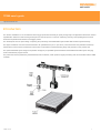
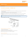
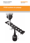
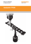
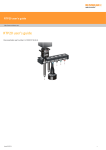
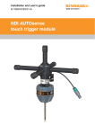
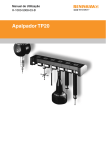
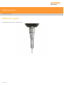
The TP200 / TP200B is a 13.5 mm diameter touch-trigger probe with the facility to quickly change stylus configurations without the need for
requalification. Electronic strain sensing techniques are used to improve on the form measuring accuracy and operating life that can be
achieved compared with kinematic touch-trigger probes.
The TP200 probe is a two piece design comprising the probe body and a detachable stylus module that holds the stylus assembly.
The stylus module has a choice of fixed overtravels: 'SF' (standard force) or 'LF' (low force). There is also the 'EO' (extended overtravel)
module which has the same overtravel force as the 'SF' but provides increased operating range and protection in the probe Z axis.
The optional SCR200 stylus change rack provides storage for pre-qualified stylus assemblies and facilitates automatic stylus changing
under measurement program control.
The probe and rack are powered by the dedicated PI 200-3 interface, which performs signal processing and communicates with the CMM
controller.
Issued 11 2014
7
TP200 user's guide
http://www.renishaw.com
Product description
Probe body
The TP200 probe body houses the strain sensing structure and electronic processing circuitry.
When the stylus contacts the workpiece, in a normal gauging move, the force applied to the stylus tip is transferred, through the stylus
module and the coupling at the front of the probe body, to the silicon strain sensors. A tip deflection of a few μm is sufficient to trigger the
probe. The probe's signals are amplified and processed in a hybrid microcircuit electronic assembly. The probe's data and control signals
are communicated between the probe and the PI 200-3 interface over a pair of screened wires, allowing the TP200 system to be
compatible with the majority of Renishaw probe heads and accessories.
The TP200B probe body uses the same technology as the TP200 probe body but has been designed to have a higher tolerance to
vibration. This helps to overcome the problem of 'air' trigger generation which can arise from vibrations transmitted through the CMM or
when using long styli with fast positioning speeds.
NOTE: Renishaw does not recommend the use of TP200B with the LF module or cranked / star styli.
The stylus module is held in position on the front of the probe body by a magnetic, kinematic coupling. The coupling allows the stylus module
to be removed and then replaced such that the stylus tip returns to a highly repeatable spatial position, eliminating the need for
requalification.
Issued 11 2014
8
TP200 user's guide
http://www.renishaw.com
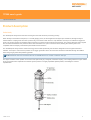
Stylus module
The stylus module carries the M2 stylus mount and provides overtravel in the X, Y and +Z probe axes. Overtravel in the -Z probe axis is
accommodated by separation of the module from the probe body.
There are three modules available, with two different overtravel forces:
1. The SF (standard force) module is suitable for most applications.
2. The LF (low force) module is recommended for use with small precision ball styli or on delicate materials.
3. The EO (extended overtravel) module is recommended for use when increasing the speed of the CMM may lead to stopping distances
which exceed the overtravel range provided in the SF / LF modules. The EO module has an additional 8 mm of overtravel in the probe Z
axis to protect against damage to the probe body in such circumstances. Overtravel force is the same as the SF module.
The module houses the mating half of the magnetically held kinematic coupling (see 'Assembling a stylus on a stylus module'), which
ensures repeatable positioning on the probe body. The coupling consists of three bearing points formed by the V grooves on the rear of the
stylus module, which seat on three ball bearings located on the front of the probe body. The fourth V groove and semi-recessed ball form an
alignment feature to ensure that the module has a unique orientation in the rotational axis. The module and stylus axis will be visibly
misaligned if the coupling is not correctly seated.
Alignment symbols are provided to assist manual alignment. The module cover forms a sliding ring (see 'Probe body'), which transfers
excess force to the case of the probe body if the maximum Z axis overtravel distance is exceeded.
PI 200-3 interface
The PI 200-3 interface unit powers and services the TP200 / TP200B probe and up to two SCR200 stylus change racks. The PI 200-3 will
service kinematic switching probes (TP2, TP20, TP6), in addition to the TP200 / TP200B. The PI 200-3 automatically recognises the probe
type, determines the status of the probe and transmits probe trigger signals to the CMM controller.
When automatic stylus changing is performed using the SCR200 change rack, the PI 200-3 inhibits probe triggering and resets the TP200 /
TP200B probe to account for the loading effects of the new stylus assembly on the strain sensors. In the event of rack overtravel or error
condition, the PI 200-3 transmits signals to the CMM controller to stop CMM motion.
During high speed position moves (fast traverse), it is necessary to reduce probe sensitivity to prevent vibration causing unwanted triggers.
The CMM controller automatically switches the PI 200-3 into a low sensitivity mode, such that vibration triggers are prevented. However, a
trigger is still issued to stop CMM motion, if an unexpected collision occurs. This mode is known as ‘probe damped mode' and is indicated
by an LED on the PI 200-3 front panel.
NOTE: The probe cannot take accurate points when damped mode is selected.
The CMM manufacturer sets the configuration of the PI 200-3 and it should not be necessary for the user to make adjustments except to
operate the reset button, as explained later in this handbook.
Issued 11 2014
9
TP200 user's guide
http://www.renishaw.com
SCR200 stylus change rack
The SCR200 holds and protects up to six stylus modules for automatic changing. The modules are magnetically held in the docking ports,
which allows the rack to be mounted in any orientation and eliminates the need for high accuracy positioning. No special commands are
necessary, as stylus changing requires only simple position moves to be programmed.
The SCR200 incorporates a system of infrared light beams and a Hall effect sensor to detect the presence of the probe and to signal to the
PI 200-3 interface that stylus changing is in progress. A self-test mode checks operation of the light beams during power-up.
The rack is provided with an overtravel mechanism to reduce the possibility of damage should a collision occur. When the mechanism is
deflected, signals are transmitted to the CMM controller to stop CMM motion. The overtravel mechanism is self-resetting. After a collision,
the rack should return to its normal operating position and should not require re-datuming.
Issued 11 2014
10
TP200 user's guide
http://www.renishaw.com
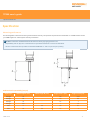
Specification
Measuring performance
The following data is derived from test rig measurements and may not represent the performance achievable on a CMM. Please contact
your CMM supplier for overall system accuracy information.
NOTES: Tested with standard Renishaw M2 steel and GF styli gauging speed 8 mm/s.
Repeatability and XY (2D) form measurements as specified to Renishaw in-house test standards.
3D form measurements as specified to standard ASME B89.4.1-1997 for point-to-point probing.
Unidirectional repeatability (2σ μm)
Stylus type
Offset length A (mm)
Offset length B (mm)
Trigger level 1 (µm)
Trigger level 2 (µm)
Straight
10
-
0.2
0.25
Straight
50
-
0.4
0.5
Straight
70
-
0.7
1
Straight
100
-
1
1.2
Star
5
20
0.5
0.7
Star
50
20
0.7
1
Issued 11 2014
11
TP200 user's guide
http://www.renishaw.com
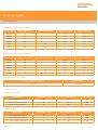
XY (2D) form measurement deviation
Stylus type
Offset length A (mm)
Offset length B (mm)
Trigger level 1 (µm)
Trigger level 2 (µm)
Straight
10
-
±0.4
±0.5
Straight
50
-
±0.8
±0.9
Straight
70
-
±0.9
±1.5
Straight
100
-
±1.7
±2
Star
5
20
±1
±1.2
Star
50
20
±1
±1.2
XYZ (3D) form measurement deviation
Stylus type
Offset length A (mm)
Offset length B (mm)
Trigger level 1 (µm)
Trigger level 2 (µm)
Straight
10
-
±0.65
±0.9
Straight
50
-
±1
±1.4
Straight
70
-
±2
±3
Straight
100
-
±4
±5.5
Star
5
20
±1.5
±2.2
Star
10
20
±3
±4
Repeatability of stylus change
Automatic change with SCR200
Manual change
1 μm max.
2 μm typical
Overtravel forces
Standard force module
Stylus length
XY axis low force (g)
XY axis high force (g)
Z+ axis (g)
20 mm at typical overtravel
45
70
490
50 mm at typical overtravel
20
40
490
50 mm at max. overtravel
25
50
1500
Stylus length
XY axis low force (g)
XY axis high force (g)
Z+ axis (g)
20 mm at typical overtravel
20
30
160
50 mm at typical overtravel
10
15
160
50 mm at max. overtravel
15
25
450
Low force module
Issued 11 2014
12
TP200 user's guide
http://www.renishaw.com
Overtravel limits
XY axis
Z+ axis
Z- axis
±14°
4.5 mm (SF / LF)
12.5 mm (EO)
4 mm
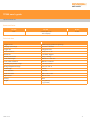
Technical data
Trigger forces
0.002 N (2 gF) (at 50 mm stylus tip)
Gauging speed range
0.5 mm/s - 80 mm/s
Trigger rate
5 triggers/s max
Sense directions
6 way: ±X, ±Y, ±Z
Module life
>10 million triggers
Module pull-off force
800 g - 1000 g
Probe cable length
Max 50 m × 0.22 mm²
Probe cable resistance
Max 5Ω / conductor
Operating temperature range
+10 °C to +40 °C
Storage temperature range
10 °C to +70 °C
Probe length
43 mm
Probe diameter
13.5 mm
Probe connector
M8 × 1.25 × 5 mm
Stylus mount
M2 × 0.4 mm
Sealing
IP30
Weight
15 g (sensor)
7 g (module)
Issued 11 2014
13
TP200 user's guide
http://www.renishaw.com
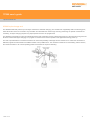
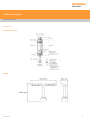
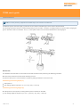
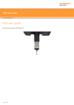
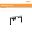
Dimensions
TP200 probe system
SCR200
Issued 11 2014
14
TP200 user's guide
http://www.renishaw.com
Installation procedure - TP200 probe
Mounting the probe body on the probe head
CAUTION: Take great care not to drop the probe when installing.
Mount the probe body on the probe head before fitting a stylus module.
Probe heads with M8 connector
Screw the threaded end of the probe body into the M8 connector, on the probe head, until it is finger-tight
Fit the S1 ‘C' spanner (supplied) to the location holes and tighten by hand
The recommended tightening torque is 0.3 Nm - 0.5 Nm
Probe heads with Renishaw autojoint
Before fitting to the probe head, screw the probe body to a PAA series adaptor, as instructed above for M8 heads
Locate the adaptor on the probe head and lock the autojoint using an S10 key
Issued 11 2014
15
TP200 user's guide
http://www.renishaw.com
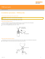
Assembling a stylus on a stylus module
For a one-piece stylus, screw the stylus into the threaded mount on the stylus module until finger-tight. Fit an S7 pin spanner (supplied) into
the stylus cross-hole and tighten using finger pressure to achieve the recommended torque of between 0.05 Nm and 0.15 Nm.
NOTE: The maximum permissible torque is 0.3 Nm.
Where an offset or star stylus arrangement is to be used, assemble the arrangement loosely and offer the module up to the probe body to
check alignment. Adjust the alignment with the module removed and tighten as described above using one or two S7 pin spanners as
necessary.
Styli from the Renishaw GF (carbon fibre reinforced plastic) range must be tightened using the S20 tightening tool (supplied with the stylus
kit). When tightening GF styli or extension pieces do not apply torque to the stylus stem. It may be necessary to use two S20 tools or S20
and S7 tools in combination to tighten adjacent threaded couplings. Refer to the instruction leaflet (Renishaw part number H-1000-4003)
provided with the stylus kit.
Mounting the stylus module on the probe body
Visually examine the mating faces of the stylus module and the probe body for dirt or other contamination. Clean if necessary using the
CK200 cleaning material (supplied), (refer to the 'Maintenance' section).
Offer up the stylus module to the probe body ensuring that the alignment symbols are matched. Allow the stylus module to engage under the
pull of the magnetic force.
Reset the probe as described in the following section 'Resetting the probe'.
Issued 11 2014
16
TP200 user's guide
http://www.renishaw.com
Resetting the probe
Press the RESET button, on the front panel of the PI 200-3 interface, for two seconds to reset the probe to the seated (armed) state.
CAUTION: Probe triggers are inhibited when the RESET button is pressed. Before pressing the button, the CMM must be stationary
with the probe stylus clear of the workpiece.
NOTE: When the TP200 is mounted on a motorised head, the action of unlocking and locking the head will perform the same function
as the RESET button.
Issued 11 2014
17
TP200 user's guide
http://www.renishaw.com
TP200 probe operation
The TP200 probe has two normal operating states - armed or triggered. The probe should be in the armed state except for the moments
when the stylus is deflected against the workpiece.
Probe armed
When the probe is armed (sometimes called ‘seated' or ‘reset') the following PI 2003 front panel indicators will be ON:
POWER ON
TYPE - TP200
PROBE - SEATED
Additionally, the probe head LED will be ON and the LEDs on the TP200 probe body will be OFF. The probe LEDs may sometimes glow
slightly, indicating a low level of background vibration.
Probe triggered
When the stylus touches the workpiece the LEDs on the probe body turn ON brightly. The SEATED and probe head LEDs will turn OFF.
The probe should be allowed to remain in the triggered state only for the minimum time necessary to reverse the CMM motion and back-off
from the workpiece.
If the probe remains in the triggered state for more than 10 seconds, drift of the stylus zero reference position will occur and the PI 200-3 will
emit an audible warning. Back-off the probe from the workpiece and refer to 'Resetting the probe'.
Changing a stylus module manually
Ensure the CMM will remain stationary, in a safe condition.
Remove the stylus module and store safely.
To fit another module, refer to the 'Mounting the stylus module to the probe body' section.
When using MH8 or MIH probe heads, unlock and relock the head before resetting the probe.
Reset the probe, refer to the 'Resetting the probe' section.
Operation with a manual probe head
After manually re-orientating the probe when using PH1, MH8 or MIH probe heads, reset the probe. Refer to the 'Resetting the probe'
section.
Issued 11 2014
18
TP200 user's guide
http://www.renishaw.com
Stylus module selection
The SF module is satisfactory for the majority of applications and provides the maximum stylus carrying capability.
The LF module should be employed where the application necessitates the use of styli with ball diameters less than 1 mm, particularly the
PS29R (Renishaw part number A-5000-7800), or where lower overtravel force will reduce the risk of marking or deflecting the surface of the
workpiece.
The EO module is recommended for use when increasing the speed of the CMM may lead to stopping distances which exceed the
overtravel range provided in the SF / LF modules.
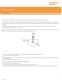
Note that the overtravel force, in the X-Y axis, varies with both direction and displacement for a given stylus length. In the X-Y axis there is a
pattern of 3 maximum and minimum force directions as illustrated in figure below.
Stylus selection
To obtain the best performance apply the following considerations when selecting and fitting a stylus:
Use the shortest possible stylus length
Minimise the mass of the stylus by using the types with ceramic or GF stems where possible - refer to the Renishaw stylus catalogue for
further information
Work within the recommended stylus limits
Ensure that stylus balls, threads and mating faces are kept clean
Tighten styli using only the tools provided
Use the stylus changing facility to optimise the styli for accuracy and feature access
Always qualify the styli at the gauging speed set for the part measurement program. If the speed is changed re-qualify the stylus tips
Issued 11 2014
19
TP200 user's guide
http://www.renishaw.com
Recommended stylus limits
The absolute maximum stylus carrying ability of the TP200 probe is determined by the mass of the stylus and the distance from the stylus
holder to the centre of gravity. The limits are:Low force module
Standard force module
3 g at 20 mm
8 g at 50 mm
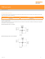
In practice, the stylus carrying is restricted by CMM vibration level, probe orientation and CMM controller flexibility. The recommended limits
are given in the figures below.
It may be possible to exceed the recommended limits but the user is advised to conduct trials to establish the suitability for the application
and the effect on measuring performance.
Recommended stylus limits - LF module:
Recommended stylus limits - SF / EO modules:
Issued 11 2014
20
TP200 user's guide
http://www.renishaw.com
Trigger level
Under certain conditions, vibration may cause false ‘air' triggers during gauging and it may be necessary to reduce the probe sensitivity.
False triggers may occur when large or heavy stylus arrangements are used, or where there is floor transmission from nearby machinery or
vehicles.
Trigger level 1 - the highest sensitivity mode, provides the best measuring accuracy
Trigger level 2 - lower sensitivity to vibration but with a small loss of measuring accuracy
The trigger level is selected by switch 10 on the rear panel of the PI 200-3 interface:
Level 1 - switch 10 DOWN
Level 2 - switch 10 UP
NOTE: For versions of the PI 200-3 prior to V9, the trigger level was adjusted by switch 11.
The trigger level selection does not affect sensitivity when the probe is in damped mode.
Please consult your CMM supplier before making any adjustment to the PI 200-3 settings.
All stylus tips must be re-qualified after changing the trigger level.
Issued 11 2014
21
TP200 user's guide
http://www.renishaw.com
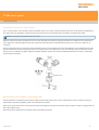
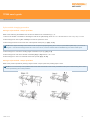
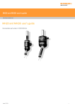
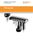
Installation procedure - SCR200 rack
Mounting the SCR200 rack on the CMM
Place the location piece over a threaded insert at the desired location on the CMM table and screw down using a M8 or M10 bolt and
hexagon key (supplied)
A special location piece with integral bolt is available for M12 inserts (Renishaw part number M-1371-0298)
Tighten the M12 location piece using a S1 ‘C' spanner (supplied with the probe kit)
Locate the base of the SCR200 rack over the location piece and partially tighten the fixing screw using the 1.5 mm AF hexagon key
(supplied)
Before fully tightening the fixing screw, rotate the rack and align with the CMM axes as described in the following procedure
NOTES: Your CMM supplier's instructions will indicate the preferred method of alignment. Alignment of the SCR200 with the CMM
axes may be essential for some measurement programs or may be desirable for ease of programming.
Mounting the SCR200 rack on the CMM:
Aligning the SCR200 rack to the CMM axes
Align the rack approximately by eye.
Take points P1 and P2 (see ‘Datuming the SCR200 rack').
Carefully rotate the rack until the runout between points P1 and P2 is less than 0.2 mm.
Tighten the fixing screw using the 1.5 mm AF hexagon key (supplied).
Datuming the SCR200 rack
Renishaw recommends that the PS2R stylus (supplied) is used to datum the SCR200 rack.
Issued 11 2014
22
TP200 user's guide
http://www.renishaw.com
NOTE: For racks previously supplied with a PS35R stylus, the instructions are identical.
If a different stylus is used, the length (L) (minimum 20 mm) and the ball radius (R) must be used to calculate offsets.
The following instructions assume uncompensated probing points are taken. Therefore, the target positions for stylus module changing are
given in absolute machine coordinates. The X, Y, Z axis system refers to the rack axes indicated in the following figure:
IMPORTANT:
The SCR200 rack must NOT be connected to the PI 200-3 interface when performing the datuming procedure.
Remove the electrical connector before datuming the rack
Open the lids of ports 1 and 6 and latch in position by sliding towards the centre of the rack
Establishing the docking depth (Y)
Take point P3
The docking depth for all ports is: {Y = P3 + R (1 mm) + 14.0 mm}
Establishing the docking height (Z)
Take point P4 on the top face, ensuring that the point is not taken on the label
The docking height for all ports is: {Z = P4 – L (20 mm) – R (1 mm) – 18.6 mm}
Issued 11 2014
23
TP200 user's guide
http://www.renishaw.com
Establishing the X-axis docking centres for ports 1, 2 and 3 (X1, X2, X3)
Take points P5 and P6 using the stylus shank to gauge the edges of the module retention plate in port 1
The docking centre for port 1: {X1 = centre point P5/P6}
The docking centre for port 2: {X2 = X1 + 30 mm}
The docking centre for port 3: {X3 = X1 + 60 mm}
Establishing the X-axis docking centres for ports 4, 5 and 6 (X4, X5, X6)
Take points P7 and P8 using the stylus shank to gauge the edges of the module retention plate in port 6
The docking centre for port 6 is: {centre point P7/P8 = X6}
The docking centre for port 4: {X4 = X6 - 60 mm}
The docking centre for port 5: {X5 = X6 - 30 mm}
Summary of docking target coordinates
Port 1 = X1, Y, Z
Port 2 = X2, Y, Z
Port 3 = X3, Y, Z
Port 4 = X4, Y, Z
Port 5 = X5, Y, Z
Port 6 = X6, Y, Z
CAUTION: The constant Y value assumes the SCR200 is aligned to your CMM axes or is using its own coordinate system.
After datuming the rack
Close the lids of ports 1 and 6
Select the operating mode (Tamper proof ON or OFF, refer to the 'Operating modes' section)
Connect the cable to the PI 200-3 interface and observe the POWER and STATUS LEDs for correct indication
Refer to the 'Loading stylus modules into the rack' section
Issued 11 2014
24
TP200 user's guide
http://www.renishaw.com
SCR200 electrical connection
Suitable cables for connection of the SCR200 rack to the PI 200-3 interface are available from Renishaw in three standard lengths:
Cable name
Part number
Length
PL63
A-1016-7630
5 m (196.85 in)
PL64
A-1016-7631
10 m (393.7 in)
PL65
A-1016-7632
15 m (590.55 in)
For applications requiring a second rack, a dual rack splitter cable is available.
Cable name
Part number
Length
PL97
A-1016-7660
260 mm (10.24 in)
NOTE: 2 × standard rack cables of the correct length will be required in addition to the dual SCR200 adaptor cable, which must be
installed at the PI 200-3 end.
Issued 11 2014
25
TP200 user's guide
http://www.renishaw.com
SCR200 rack operation
Operating modes
The SCR200 may be operated in either of two modes depending on the application requirements and whether the SCR200 is accessible in
normal operation.
With TAMPER PROOF ON selected, the stylus change cycle is initiated by moving the probe across the face of the Hall sensor, for the rack
to detect the presence of the probe before entering a docking port. In this mode, interruption of the light beams alone does not inhibit probe
triggering and therefore the probe cannot be accidentally inhibited during normal operation. For example by placing fingers in the light beam
or by operating a port lid.
With TAMPER PROOF OFF selected, direct entry to the rack ports is allowed. The light beams detect the probe entering a module docking
port and inhibit probe triggers. In this mode faster stylus changing is possible but Renishaw recommend that it is used only in situations
where access to the rack is restricted when the CMM is operating automatically.
To select the operating mode:
Remove the electrical connector
Move the mode selection slide switch (see 'Mounting the SCR200 rack on the CMM') - LEFT for tamper proof ON, RIGHT for tamper
proof OFF
Replace the electrical connector
Confirm that the POWER and STATUS lamps are indicating the correct mode
Loading stylus modules into the rack
Renishaw recommends that the stylus modules are mounted on the probe body by hand. An automatic stylus change routine is completed
prior to tip qualification then the stylus module is loaded into the rack.
The CMM should be used to load the stylus modules into the rack by following the 'Stylus module changing procedure'.
It is possible to load the rack by hand but care must be taken to ensure correct rotational alignment, as there is no warning if a module is
incorrectly seated on the probe sensor and gross measurement errors will occur.
Power and status indicators
Two LEDs are located on the top face of the rack:1. POWER - green
2. STATUS - red
Power
Status
SCR200 mode
OFF
Flashing for 10 s
Self-test, tamper proof ON
OFF
Flashing for 5 s
Self-test, tamper proof OFF
ON
OFF
Rack idle, tamper proof ON
ON
ON
Rack idle, tamper proof OFF
ON
Flashing
Stylus changing
Flashing
Flashing
Self-test failed
Issued 11 2014
26
TP200 user's guide
http://www.renishaw.com
Stylus module changing procedure
Storing a stylus module - tamper proof ON
Refer to the 'Datuming the SCR200 rack' section for definitions of coordinate X(n), Y, Z.
1. Move to the START coordinate for activating the Hall sensor: {Xs, Ys, Z}, where Xs = X1 + 82 mm and Ys = P3 + R (1 mm) - 7.5 mm.
2. Move along the X- axis to: {Xs - 12 mm} at a minimum speed of 5 mm/s.
3. Move along the X axis to the centre line of the required vacant port (n): {X(n), Ys, Z}
NOTE: If the stylus assembly has an offset or star component projecting along the Y+ axis, it is permissible (after step 1) to move out
along the Y- axis and exit the light beam for a max i mum of 5s, to avoid a collision with the SCR200 leg or another stored stylus.
4. Move along the Y+ axis to the docking target coordinate for port (n): {X(n), Y, Z}
5. Move along the Z+ axis to the release coordinate: {X(n), Y, Zr} where Zr = Z + 3 mm.
6. Move along the Y- axis to a coordinate clear of the port lid: {X(n), Ys, Zr}
Storing a stylus module - tamper proof OFF
Refer to the previous procedure ('Storing a stylus module - tamper proof ON') omitting steps 1 and 2.
NOTE: It is not necessary to stop CMM motion at the start coordinate in this mode, provided that the port is entered along the Y+ axis
at the specified X(n) and Z axis positions.
Issued 11 2014
27
TP200 user's guide
http://www.renishaw.com
Picking up a stylus module
This procedure is applicable to both operating modes. Refer to the section 'Datuming the SCR200 rack' for definitions of coordinate X(n),
Y, Z.
1.
2.
3.
4.
From the previous port coordinate: {X(n), Ys, Zr}, move along the X axis to the port (n) containing the required stylus module: {X(n), Ys, Zr}
Move along the Y+ axis to the port centre: {X(n), Y, Zr}
Move along the Z- axis to the docking target coordinate for port (n): {X(n), Y, Z}
Move along the Y- axis to a coordinate clear of the port lid: {X(n), Ys, Z}
Proceed with the part measurement program.
Issued 11 2014
28
TP200 user's guide
http://www.renishaw.com
Maintenance
TP200 probe body and stylus module
The kinematic coupling mechanism, connecting the probe body to the stylus module, incorporates precision ball / V groove seatings. The
coupling mechanism has been tested in a wide range of environments and is highly tolerant of non-metallic dust, but regular inspection and
cleaning with the CK200 material (supplied) is recommended to ensure continued high performance. Instructions for use are included with
the cleaning material (Renishaw part number A-1085-0016).
The user should determine the frequency of cleaning according to the conditions of use.
Stylus balls, threads and mating faces should be cleaned with a proprietary cleaning cloth or solvent.
Stylus modules that are not in use should be stored in spare ports in the SCR200 rack or in their transport boxes.
SCR200 rack
Periodic cleaning of the rack ports, lids and outer surfaces using a proprietary cleaning cloth, is recommended to prevent contamination of
the modules.
Issued 11 2014
29
TP200 user's guide
http://www.renishaw.com
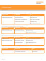
Fault finding
The CMM will not register a probe trigger, but the probe operates normally when the stylus is deflected by hand:
PI 200-3 indicators
Possible causes
Remedy
'STOP' lamp ON.
The CMM controller or a Renishaw system has
activated STOP signal.
Check status of Renishaw motorised probe head or
other systems.
SCR200 overtravel mechanism is deflected.
Clear obstruction and allow overtravel mechanism to
reset.
'TP200' lamp ON.
'SEATED' LED operates
normally.
The probe fails to trigger and the probe LEDs glow only dimly when the stylus touches the workpiece, but the probe operates normally when
the stylus is deflected by hand:
PI 200-3 indicators
Possible causes
Remedy
'SEATED' LED ON.
The trigger speed is too slow.
Probe normally to the workpiece surface.
The stylus is too heavy.
Increase gauging speed.
The probe will not arm or the probe does not stay armed when the RESET button is released. The probe LEDs are always OFF:
PI 200-3 indicators
Possible causes
Remedy
'STD' LED ON.
Probe sensor faulty.
Remove probe and test by substitution.
'SEATED' LED OFF.
Probe wiring open circuit.
Check wiring from probe to PI 200-3 interface.
The probe will not arm or the probe does not stay armed when the RESET button is released. The probe LEDs are always ON:
PI 200-3 indicators
Possible causes
Remedy
'TP200' LED ON.
Probe sensor faulty or damaged by collision.
Remove probe and test by substitution.
'SEATED' LED OFF.
Issued 11 2014
30
TP200 user's guide
http://www.renishaw.com
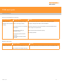
False (‘air') triggers occur while the CMM is stationary and the probe LEDs flicker:
PI 200-3 indicators
Possible causes
Remedy
'TP200' LED ON.
Probe sensor faulty.
Remove probe and test by substitution.
'SEATED' LED operates normally.
Probe loose in probe head.
Correctly tighten probe.
Excessive vibration from external source.
Remove cause or isolate CMM.
Excessive vibration from CMM.
Check CMM air supply.
Maintain CMM air bearing system.
False (‘air') triggers occur at gauging speed and the probe LEDs flicker:
PI 200-3 indicators
Possible causes
Remedy
'DAMPED' LED is OFF.
Stylus is too large or heavy.
Use stylus arrangements within recommendations.
'SEATED' LED operates normally.
Excessive vibration from CMM.
Check CMM air supply.
Maintain CMM air bearing system.
False (‘air') triggers occur at traverse speed and the probe LEDs flicker:
PI 200-3 indicators
Possible causes
Remedy
'DAMPED' LED is ON.
Stylus is too large or heavy.
Use stylus arrangements within recommendations.
'SEATED' LED operates normally.
Excessive vibration from CMM.
Check CMM air supply.
Traverse speed is too high.
Maintain CMM air bearing system.
Reduce traverse speed.
The probe triggers during an SCR200 stylus change:
PI 200-3 indicators
Possible causes
Remedy
'SEATED' LED operates normally.
The SCR200 is not connected to the PI 200-3.
Check SCR200 indicator lamps.
Incorrect SCR200 operating mode.
Re-connect cable.
Issued 11 2014
31
TP200 user's guide
http://www.renishaw.com
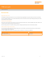
There is an unexpected loss of accuracy:
PI 200-3 indicators
Possible causes
Remedy
'TP200' LED ON.
Stylus ball is damaged or dirty.
Inspect and clean stylus ball, or replace and re-qualify the stylus.
'SEATED' LED operates Stylus is too large or heavy.
Use stylus arrangements within recommendations.
normally.
The probe is loose or not correctly Check the stylus joints. Ensure the module is correctly seated and the
assembled.
probe is tight in the probe head.
The kinematic coupling is
damaged or dirty.
Inspect and clean the kinematic coupling.
Re-qualify stylus tips.
The gauging speed has been
changed.
The trigger threshold has been
changed.
Deflection alarm active:
PI 200-3 indicators
Possible causes
Audible indicator ON. The stylus is or was deflected for >10s.
Remedy
Move the stylus clear of any obstruction and press the RESET button
Stylus module was changed manually.
Issued 11 2014
32
TP200 user's guide
http://www.renishaw.com
Accessories
High performance styli
For applications requiring styli longer than 40 mm, the Renishaw range of lightweight ‘GF' styli and extension pieces are recommended.
These are available individually or as a boxed kit (Renishaw part number A-5003-2310). See the stylus catalogue (Renishaw part number
H-1000-3200) for further information.
Extension bars and adaptors
Probe reach may be extended, with minimal loss of accuracy using probe extension bars. These are available in M8 - M8 or autojoint - M8
connector versions according to the type of probe head in use.
See the ‘Probing systems for coordinate measuring machines' catalogue (Renishaw part number H10005050) for details.
MSR1 module storage rack (manual)
For manual stylus changing applications the MSR1 storage rack is recommended. The rack holds and protects up to 6 stylus modules
carrying pre-qualified stylus arrangements.
The rack is available with a bracket for wall mounting or with a leg and base for mounting on the CMM table.
MSR1 (wall mounted)
A-1371-0330
MSR1 (CMM table mounted)
A-1371-0347
Issued 11 2014
33
TP200 user's guide
http://www.renishaw.com
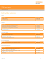
Part number summary
Probes:
Description
Part number
TP200 probe body
A-1207-0020
TP200B probe body
A-1207-0056
Probe kits:
Description
Part number
TP200 probe kit 1 (including standard force module)
A-1207-0001*
TP200 probe kit 2 (including low force module)
A-1207-0002*
TP200B probe kit 1 (including standard force module)
A-1207-0055*
TP200B probe body only
A-1207-0056
TP200 stylus modules:
Description
Part number
TP200 standard force stylus module
A-1207-0010
TP200 low force stylus module
A-1207-0011
TP200 extended overtravel stylus module
A-1207-0012
PI 200-3 probe interface:
Description
Part number
PI 200-3 probe interface for TP1, TP2, TP6, TP20 and TP200
A-1207-0050
SCR200 stylus changing rack:
Description
Part number
SCR200 kit- active six port change rack for use with TP200
(including 3 × standard force stylus modules)
A-1207-0030#
SCR200 kit - active six port change rack for use with TP200
(including 3 × low force stylus modules)
A-1207-0070#
SCR200 only
A-1207-0260
Issued 11 2014
34
TP200 user's guide
http://www.renishaw.com
MSR1 module storage rack:
Description
Part number
MSR1 - manual storage rack with wall mounting brackets
A-1371-0330
MSR1 - manual storage rack with leg and mounting base
A-1371-0347
TP200 accessories:
Description
Part number
M12 location piece (re: SCR200)
M-1371-0298
PL63 (5 m) SCR200 to PI 200-3 cable
A-1016-7630
PL64 (10 m) SCR200 to PI 200-3 cable
A-1016-7631
PL65 (15 m) SCR200 to PI 200-3 cable
A-1016-7632
PL97 (0.26 m) dual adaptor cable for connecting 2 × SCR200 racks to PI 2003
(requires 2 × cables PL63 / PL64 / PL65) in addition
A-1016-7660
Replacements:
Description
Part number
CK200 cleaning material
A-1085-0016
S1 'C' spanner
A-1042-1486
S9 double ended 'C' spanner
A-1047-3932
S7 stylus tool
M-5000-3540
Hexagon key 1.5 mm AF
P-TL03-0150
* TP200 / TP200B probe kit contents:
TP200 probe body
Stylus module
Tools / cleaning kit
Test certificate
User's guide
# SCR200 stylus change rack kit contents:
SCR200 rack
Stylus modules (×3)
Mounting kit
Datuming stylus
Issued 11 2014
35
Renishaw plc
New Mills, Wotton-under-Edge,
Gloucestershire, GL12 8JR
United Kingdom
T +44 (0)1453 524524
F +44 (0)1453 524901
www.renishaw.com/cmmsupport
For worldwide contact details,
please visit our main website at
www.renishaw.com/contact
Issued 11 2014