1
Advanced SerialRAID Adapters
User’s Guide and
Maintenance Information
SA33-3285-01
Advanced SerialRAID Adapters
User’s Guide and
Maintenance Information
SA33-3285-01
Second Edition (September 1999)
This major revision supersedes SA33-3285-00. Technical changes are shown by a vertical line to the left of each
change.
The following paragraph does not apply to any country where such provisions are inconsistent with local law:
THIS PUBLICATION IS PRINTED “AS IS” WITHOUT WARRANTY OF ANY KIND, EITHER EXPRESS OR IMPLIED,
INCLUDING, BUT NOT LIMITED TO, THE IMPLIED WARRANTIES OF MERCHANTABILITY OR FITNESS FOR A
PARTICULAR PURPOSE. Some states do not allow disclaimer of express or implied warranties in certain transactions;
therefore, this statement may not apply to you.
This publication could contain technical inaccuracies or typographical errors. Changes are periodically made to the
information herein; these changes will be incorporated in new editions of the publication.
It is possible that this publication may contain reference to, or information about, products (machines and programs),
programming, or services that are not announced in your country. Such references or information must not be
construed to mean that such products, programming, or services will be offered in your country. Any reference to a
licensed program in this publication is not intended to state or imply that you can use only the licensed program
indicated. You can use any functionally equivalent program instead.
© Copyright International Business Machines Corporation 1996, 1999. All rights reserved.
Note to U.S. Government Users — Documentation related to restricted rights — Use, duplication, or disclosure is
subject to restrictions set forth in the GSA ADP Schedule Contract.
Contents
Safety Notices . . . . . . . . . . . . . . . . . . . . . . . xiii
Definitions of Safety Notices . . . . . . . . . . . . . . . . . . . xiii
Safety Notice for Installing, Relocating, or Servicing . . . . . . . . . . . xiii
|
About This Book . . . . . . . . . . . . . . . . . . . . . . . xv
Who Should Use This Book . . . . . . . . . . . . . . . . . . . xv
What This Book Contains . . . . . . . . . . . . . . . . . . . . xv
If You Need More Information . . . . . . . . . . . . . . . . . . . xv
Web Support Pages . . . . . . . . . . . . . . . . . . . . . . xvi
Numbering Convention . . . . . . . . . . . . . . . . . . . . . xvi
Part 1. User Information . . . . . . . . . . . . . . . . . . . . . . . . 1
|
|
Chapter 1. Introducing SSA and the Advanced SerialRAID Adapters
Serial Storage Architecture (SSA) . . . . . . . . . . . . .
The Advanced SerialRAID Adapters (type 4–P) . . . . . . . .
Fast-Write Cache Feature . . . . . . . . . . . . . .
128 MB Memory Module Feature . . . . . . . . . . . .
Lights of the Advanced SerialRAID Adapters . . . . . . . .
Port Addresses of the Advanced SerialRAID Adapters . . . . .
SSA Adapter ID during Bring-Up . . . . . . . . . . . . .
.
.
.
.
.
.
.
.
.
.
.
.
.
.
.
.
.
.
.
.
.
.
.
.
.
.
.
.
.
.
.
.
Chapter 2. Introducing SSA Loops . . . . . . . . . . . .
Loops, Links, and Data Paths . . . . . . . . . . . . . .
Simple Loop . . . . . . . . . . . . . . . . . . .
Simple Loop — One Disk Drive Missing . . . . . . . . . .
Simple Loop — Two Disk Drives Missing . . . . . . . . .
One Loop with Two Adapters in One Using System . . . . . .
One Loop with Two Adapters in Each of Two Using Systems . .
Two Loops with One Adapter . . . . . . . . . . . . .
Two Loops with Two Adapters . . . . . . . . . . . . .
Large Configurations . . . . . . . . . . . . . . . . .
Switching Off Using Systems . . . . . . . . . . . . .
Switching On Using Systems . . . . . . . . . . . . .
Configuring Devices on an SSA Loop . . . . . . . . . . .
SSA Link Speed . . . . . . . . . . . . . . . . . .
Identifying and Addressing SSA Devices . . . . . . . . . .
Location Code Format . . . . . . . . . . . . . . .
Pdisks, Hdisks, and Disk Drive Identification . . . . . . . .
SSA Unique IDs . . . . . . . . . . . . . . . . .
Rules for SSA Loops . . . . . . . . . . . . . . . . .
Checking the Level of the Adapter Microcode. . . . . . . . .
Rules for the Physical Relationship between Disk Drives and Adapters
One Pair of Adapter Connectors in the Loop . . . . . . . .
Pairs of Adapter Connectors in the Loop – Some Shared Data . .
Pairs Of Adapter Connectors in the Loop – Mainly Shared Data .
.
.
.
.
.
.
.
.
.
.
.
.
.
.
.
.
.
.
.
.
.
.
.
.
3
3
4
5
5
6
6
6
. 7
. 7
. 8
. 9
. . . . . 10
. . . . . 11
. . . . . 12
. . . . . 14
. . . . . 15
. . . . . 16
. . . . . 17
. . . . . 17
. . . . . 18
. . . . . 18
. . . . . 19
. . . . . 19
. . . . . 19
. . . . . 21
. . . . . 22
. . . . . 23
. . . . . 24
. . . . . 24
. . . . . 25
. . . . . 26
iii
Reserving Disk Drives
Fast-Write Cache . .
|
.
.
.
.
.
.
.
.
.
.
.
.
.
.
.
.
.
.
.
.
.
.
.
.
.
.
.
.
.
.
.
.
.
.
.
.
.
.
.
.
. 27
. 27
.
.
.
.
.
.
.
.
.
.
.
.
.
.
.
.
.
.
.
.
.
.
.
.
.
.
.
.
.
.
.
.
.
.
.
.
.
.
.
.
.
.
.
.
.
.
.
.
.
.
.
.
.
.
.
.
.
.
.
.
.
.
.
.
.
.
.
.
.
.
.
.
.
.
.
.
.
.
.
.
.
.
.
.
.
.
.
.
.
.
.
.
.
.
.
.
.
.
.
.
.
.
.
.
.
.
.
.
.
.
.
.
.
.
.
.
.
.
.
.
.
.
.
.
.
.
.
.
.
.
.
.
.
.
.
.
.
.
.
.
.
.
.
.
.
.
.
.
.
.
.
.
.
.
.
.
.
.
.
.
.
.
.
.
.
.
.
.
.
.
.
.
.
.
.
.
.
.
.
.
.
.
.
.
.
.
.
.
.
.
.
.
.
.
.
.
.
.
.
.
.
.
.
.
.
.
.
.
.
.
.
.
.
.
.
.
.
.
.
.
.
.
.
.
.
.
.
.
.
.
.
.
.
.
.
.
.
.
.
.
.
.
.
.
.
.
.
.
.
.
.
.
.
.
.
.
.
.
.
.
.
.
.
.
.
.
.
.
.
.
.
.
.
.
.
.
.
.
.
.
.
.
.
.
.
.
.
.
.
.
.
.
.
.
.
.
.
.
.
29
29
29
30
31
31
31
32
33
33
33
33
34
34
35
36
36
37
37
37
37
38
38
Chapter 4. Using the SSA SMIT Menus . . . .
Getting Access to the SSA Adapters SMIT Menu .
Getting Access to the SSA Disks SMIT Menu. . .
Getting Access to the SSA RAID Arrays SMIT Menu
.
.
.
.
.
.
.
.
.
.
.
.
.
.
.
.
.
.
.
.
.
.
.
.
.
.
.
.
.
.
.
.
.
.
.
.
.
.
.
.
.
.
.
.
39
39
40
42
Chapter 3. RAID Functions and Array States
RAID Functions . . . . . . . . . .
Availability . . . . . . . . . . .
Disk Drives That Are Not in Arrays . . .
RAID-0 Array States . . . . . . . . .
Good State . . . . . . . . . . .
Offline State. . . . . . . . . . .
RAID-1 Array States . . . . . . . . .
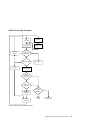
RAID-5 Array States . . . . . . . . .
Good State . . . . . . . . . . .
Exposed State . . . . . . . . . .
Degraded State . . . . . . . . .
Rebuilding State . . . . . . . . .
Offline State. . . . . . . . . . .
RAID-5 Array State Flowchart . . . . .
RAID-10 Array States . . . . . . . .
Good State . . . . . . . . . . .
Exposed State . . . . . . . . . .
Degraded State . . . . . . . . .
Rebuilding State . . . . . . . . .
Offline State. . . . . . . . . . .
Unknown State . . . . . . . . . .
Multiple States . . . . . . . . . .
|
|
|
|
|
|
|
|
|
|
|
|
|
|
|
Chapter 5. Hot Spare Management . . . . . . . . . .
Deciding how to Configure Hot Spare Disk Drive Pools . . . .
Choosing How Many Hot Spare Disk Drives to Include in Each Pool
Choosing the Error Threshold (Alarm) Level for a Hot Spare Pool .
Rules for Hot Spare Disk Drive Pools . . . . . . . . . .
Solving Hot Spare Pool Problems . . . . . . . . . . .
.
.
.
.
.
.
.
.
.
.
.
.
.
.
.
.
.
.
.
.
.
.
.
.
.
.
.
.
.
.
.
.
.
.
.
.
43
43
49
49
50
51
|
|
|
|
|
Chapter 6. Using the RAID Array Configurator . . . . .
Installing and Configuring SSA RAID Arrays . . . . . . .
Getting Access to the SSA RAID Arrays SMIT Menu . . .
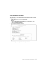
Adding an SSA RAID Array. . . . . . . . . . . .
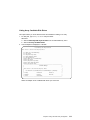
Deleting an SSA RAID Array . . . . . . . . . . .
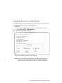
Creating a Hot Spare Disk Drive . . . . . . . . . .
Changing or Showing the Status of a Hot Spare Pool . . .
Showing the Disks That Are Protected by Hot Spares . . .
Listing the Disks That Are in a Hot Spare Pool . . . . .
Adding a New Hot Spare Pool. . . . . . . . . . .
Adding Disks to, or Removing Disks from, a Hot Spare Pool.
.
.
.
.
.
.
.
.
.
.
.
.
.
.
.
.
.
.
.
.
.
.
.
.
.
.
.
.
.
.
.
.
.
.
.
.
.
.
.
.
.
.
.
.
.
.
.
.
.
.
.
.
.
.
.
.
.
.
.
.
.
.
.
.
.
.
55
56
57
58
68
70
72
75
78
81
84
iv
Advanced SerialRAID Adapters User and Maintenance Information
.
.
.
.
.
.
.
.
.
.
.
Dealing with RAID Array Problems . . . . . . . . . . . . . .
Getting Access to the SSA RAID Array SMIT Menu . . . . . . . .
Identifying and Correcting or Removing Failed Disk Drives . . . . .
Installing a Replacement Disk Drive . . . . . . . . . . . . .
Using Other Configuration Functions . . . . . . . . . . . . .
Getting Access to the SSA RAID Array SMIT Menu . . . . . . . .
Listing All Defined SSA RAID Arrays. . . . . . . . . . . . .
Listing All Supported SSA RAID Arrays . . . . . . . . . . . .
Listing All SSA RAID Arrays That Are Connected to a RAID Manager .
Listing the Status of All Defined SSA RAID Arrays . . . . . . . .
Listing or Identifying SSA Physical Disk Drives . . . . . . . . .
Listing or Deleting Old RAID Arrays Recorded in an SSA RAID Manager
Changing or Showing the Attributes of an SSA RAID Array . . . . .
Changing Member Disks in an SSA RAID Array . . . . . . . .
Changing or Showing the Use of an SSA Disk Drive . . . . . . .
Changing the Use of Multiple SSA Physical Disks . . . . . . . .
.
.
.
.
.
.
.
.
.
.
.
.
.
.
.
.
|
|
|
|
|
|
|
|
Chapter 7. Split-Site Management . . . . . . . . . . . . . .
Configuration of RAID-1 and RAID-10 Arrays . . . . . . . . . . .
Operation after a Loss of Member Disks . . . . . . . . . . . . .
One Half of the Array Is Not Present . . . . . . . . . . . . .
Array is Offline because Adapter Is Not Known to the Remaining Half of the
Array . . . . . . . . . . . . . . . . . . . . . . .
Array is Offline because the Split and Join Procedure Was Not Performed
Correctly . . . . . . . . . . . . . . . . . . . . .
|
Chapter 8. Using the SSA Spare Tool .
|
. 157
.
. 159
.
.
.
.
. 163
Chapter 9. Using the Fast-Write Cache Feature. . . .
Fast-Write Cache Card Battery . . . . . . . . . .
Configuring the Fast-Write Cache Feature . . . . . .
Getting Access to the Fast-Write Menus . . . . . .
Enabling or Disabling Fast-Write for One Disk Drive . .
Enabling or Disabling Fast-Write for Multiple Devices. .
Bypassing the Cache in a One-Way Fast-Write Network.
Dealing with Fast-Write Problems . . . . . . . . .
SRN 42521 . . . . . . . . . . . . . . .
SRN 42524 . . . . . . . . . . . . . . .
SRN 42525 . . . . . . . . . . . . . . .
.
.
.
.
.
.
.
.
.
.
.
.
.
.
.
.
.
.
.
.
.
.
.
.
.
.
.
.
.
.
.
.
.
.
.
.
.
.
.
.
.
.
.
.
.
.
.
.
.
.
.
.
.
.
.
.
.
.
.
.
.
.
.
.
.
.
.
.
.
.
.
.
.
.
.
.
.
.
.
.
.
.
.
.
.
.
.
.
165
165
165
167
168
170
172
173
173
175
175
Chapter 10. SSA Error Logs
Error Logging . . . . . .
Summary . . . . . .
Detailed Description. . .
Error Logging Management .
Summary . . . . . .
Detailed Description. . .
Error Log Analysis . . . .
Summary . . . . . .
Detailed Description. . .
.
.
.
.
.
.
.
.
.
.
.
.
.
.
.
.
.
.
.
.
.
.
.
.
.
.
.
.
.
.
.
.
.
.
.
.
.
.
.
.
.
.
.
.
.
.
.
.
.
.
.
.
.
.
.
.
.
.
.
.
.
.
.
.
.
.
.
.
.
.
.
.
.
.
.
.
.
.
.
.
177
177
177
178
183
183
183
184
184
185
Contents
v
.
.
.
.
.
.
.
.
.
.
.
.
.
.
.
.
.
.
.
.
.
.
.
.
.
.
.
.
.
.
.
.
.
.
.
.
.
.
.
.
.
.
147
147
148
149
.
.
.
.
.
.
.
.
.
.
.
.
.
.
.
.
.
.
.
.
.
.
.
.
.
.
.
.
.
.
.
.
.
.
.
.
.
.
.
.
.
.
.
.
.
.
.
.
.
.
.
.
. 87
. 88
. 89
. 93
. 95
. 96
. 98
. 99
. 100
. 102
. 106
. 128
. 133
. 135
. 142
. 145
.
.
.
.
.
.
.
.
.
.
.
.
.
.
.
.
.
.
.
.
.
.
.
.
.
.
.
.
.
.
.
.
.
.
.
.
.
.
.
.
Good Housekeeping
.
.
.
.
.
.
.
.
.
.
.
.
.
.
.
.
.
.
.
.
Chapter 11. Using the SSA Command Line Interface for RAID Configurations
Command Syntax . . . . . . . . . . . . . . . . . . . . .
Options . . . . . . . . . . . . . . . . . . . . . . . . .
Object Types . . . . . . . . . . . . . . . . . . . . . . .
Instruct Types . . . . . . . . . . . . . . . . . . . . . . .
Examples . . . . . . . . . . . . . . . . . . . . . . . .
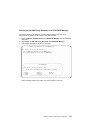
Example 1: To Create a RAID-0 Array . . . . . . . . . . . . . .
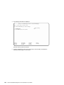
Example 2: To Create a RAID-1 Array . . . . . . . . . . . . . .
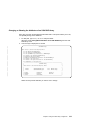
Example 3: To Create a RAID-5 Array . . . . . . . . . . . . . .
Example 4: To Create a RAID-10 Array . . . . . . . . . . . . .
Example 5: To Create a Hot Spare Pool . . . . . . . . . . . . .
Example 6: To List All Defined SSA Objects . . . . . . . . . . . .
Example 7: To Change an Attribute of an Object . . . . . . . . . .
Example 8: To Exchange a Member Disk Drive of an Existing Array . . . .
Example 9: To Make a New AIX System Disk . . . . . . . . . . .
Example 10: To Delete an Array. . . . . . . . . . . . . . . .
SSARAID Command Attributes . . . . . . . . . . . . . . . . .
RAID Arrays Creation and Change Attributes . . . . . . . . . . .
RAID Arrays Change Attributes . . . . . . . . . . . . . . . .
Hot Spare Pool Creation and Change Attribute . . . . . . . . . . .
Physical Disk Drive Change Attributes. . . . . . . . . . . . . .
Action Attributes (RAID-1, RAID-5, and RAID-10 Only) . . . . . . . .
Return Codes . . . . . . . . . . . . . . . . . . . . . . .
|
|
|
|
|
|
|
Chapter 12. Using the Programming Interface . . . . . . . . . .
SSA Subsystem Overview . . . . . . . . . . . . . . . . .
Device Drivers . . . . . . . . . . . . . . . . . . . .
Interface between the SSA Adapter Device Driver and Head Device Driver
Trace Formatting. . . . . . . . . . . . . . . . . . . .
SSA Adapter Device Driver . . . . . . . . . . . . . . . . .
Purpose . . . . . . . . . . . . . . . . . . . . . .
Syntax . . . . . . . . . . . . . . . . . . . . . . .
Description. . . . . . . . . . . . . . . . . . . . . .
PCI SSA Adapter ODM Attributes . . . . . . . . . . . . . .
Device-Dependent Subroutines . . . . . . . . . . . . . . .
Summary of SSA Error Conditions . . . . . . . . . . . . . .
Managing Dumps . . . . . . . . . . . . . . . . . . .
Files . . . . . . . . . . . . . . . . . . . . . . . .
IOCINFO (Device Information) SSA Adapter Device Driver ioctl Operation . .
Purpose . . . . . . . . . . . . . . . . . . . . . .
Description. . . . . . . . . . . . . . . . . . . . . .
Files . . . . . . . . . . . . . . . . . . . . . . . .
SSA_TRANSACTION SSA Adapter Device Driver ioctl Operation. . . . .
Purpose . . . . . . . . . . . . . . . . . . . . . .
Description. . . . . . . . . . . . . . . . . . . . . .
Return Values. . . . . . . . . . . . . . . . . . . . .
Files . . . . . . . . . . . . . . . . . . . . . . . .
SSA_GET_ENTRY_POINT SSA Adapter Device Driver ioctl Operation . . .
vi
Advanced SerialRAID Adapters User and Maintenance Information
.
.
.
. 188
.
.
.
.
.
.
.
.
.
.
.
.
.
.
.
.
.
.
.
.
.
.
189
191
192
192
192
193
193
193
194
194
195
195
195
196
196
197
198
198
201
202
203
204
205
. 207
. 207
. 207
208
. . 208
. . 209
. . 209
. . 209
. . 209
. . 209
. . 210
. . 211
. . 211
. . 212
. . 213
. . 213
. . 213
. . 213
. . 214
. . 214
. . 214
. . 215
. . 215
. . 216
Purpose . . . . . . . . . . . . . . . . . . . . . . . .
Description. . . . . . . . . . . . . . . . . . . . . . . .
Return Values. . . . . . . . . . . . . . . . . . . . . . .
Files . . . . . . . . . . . . . . . . . . . . . . . . . .
SSA Adapter Device Driver Direct Call Entry Point. . . . . . . . . . . .
Purpose . . . . . . . . . . . . . . . . . . . . . . . .
Description. . . . . . . . . . . . . . . . . . . . . . . .
Return Values. . . . . . . . . . . . . . . . . . . . . . .
ssadisk SSA Disk Device Driver . . . . . . . . . . . . . . . . . .
Purpose . . . . . . . . . . . . . . . . . . . . . . . .
Syntax . . . . . . . . . . . . . . . . . . . . . . . . .
Configuration Issues . . . . . . . . . . . . . . . . . . . .
Device Attributes . . . . . . . . . . . . . . . . . . . . . .
Device-Dependent Subroutines . . . . . . . . . . . . . . . . .
Error Conditions . . . . . . . . . . . . . . . . . . . . . .
Special Files . . . . . . . . . . . . . . . . . . . . . . .
IOCINFO (Device Information) SSA Disk Device Driver ioctl Operation . . . . .
Purpose . . . . . . . . . . . . . . . . . . . . . . . .
Description. . . . . . . . . . . . . . . . . . . . . . . .
Files . . . . . . . . . . . . . . . . . . . . . . . . . .
SSADISK_ISAL_CMD (ISAL Command) SSA Disk Device Driver ioctl Operation
Purpose . . . . . . . . . . . . . . . . . . . . . . . .
Description. . . . . . . . . . . . . . . . . . . . . . . .
Return Values. . . . . . . . . . . . . . . . . . . . . . .
Files . . . . . . . . . . . . . . . . . . . . . . . . . .
SSADISK_ISALMgr_CMD (ISAL Manager Command) SSA Disk Device Driver ioctl
Operation . . . . . . . . . . . . . . . . . . . . . . . .
Purpose . . . . . . . . . . . . . . . . . . . . . . . .
Description. . . . . . . . . . . . . . . . . . . . . . . .
Return Values. . . . . . . . . . . . . . . . . . . . . . .
Files . . . . . . . . . . . . . . . . . . . . . . . . . .
SSADISK_SCSI_CMD (SCSI Command) SSA Disk Device Driver ioctl Operation
Purpose . . . . . . . . . . . . . . . . . . . . . . . .
Description. . . . . . . . . . . . . . . . . . . . . . . .
Return Values. . . . . . . . . . . . . . . . . . . . . . .
Files . . . . . . . . . . . . . . . . . . . . . . . . . .
SSADISK_LIST_PDISKS SSA Disk Device Driver ioctl Operation. . . . . . .
Purpose . . . . . . . . . . . . . . . . . . . . . . . .
Description. . . . . . . . . . . . . . . . . . . . . . . .
Return Values. . . . . . . . . . . . . . . . . . . . . . .
Files . . . . . . . . . . . . . . . . . . . . . . . . . .
SSA Disk Concurrent Mode of Operation Interface . . . . . . . . . . .
Device Driver Entry Point . . . . . . . . . . . . . . . . . . .
Top Kernel Extension Entry Point . . . . . . . . . . . . . . . .
SSA Disk Fencing . . . . . . . . . . . . . . . . . . . . . .
SSA Target Mode . . . . . . . . . . . . . . . . . . . . . .
Configuring the SSA Target Mode . . . . . . . . . . . . . . . .
Buffer Management . . . . . . . . . . . . . . . . . . . . .
Understanding Target-Mode Data Pacing . . . . . . . . . . . . . .
Using SSA Target Mode . . . . . . . . . . . . . . . . . . .
Contents
216
216
216
216
217
217
217
217
218
218
218
218
222
224
226
228
229
229
229
229
230
230
230
231
232
233
233
233
234
234
235
235
235
236
236
237
237
237
238
238
239
239
240
242
243
244
245
245
246
vii
Execution of Target Mode Requests . . . . . . . . . . . .
SSA tmssa Device Driver . . . . . . . . . . . . . . . . .
Purpose . . . . . . . . . . . . . . . . . . . . .
Syntax . . . . . . . . . . . . . . . . . . . . . .
Description. . . . . . . . . . . . . . . . . . . . .
Configuration Information . . . . . . . . . . . . . . . .
Device-Dependent Subroutines . . . . . . . . . . . . . .
Errors . . . . . . . . . . . . . . . . . . . . . .
tmssa Special File . . . . . . . . . . . . . . . . . . .
Purpose . . . . . . . . . . . . . . . . . . . . .
Description. . . . . . . . . . . . . . . . . . . . .
Implementation Specifics . . . . . . . . . . . . . . . .
Related Information . . . . . . . . . . . . . . . . . .
IOCINFO (Device Information) tmssa Device Driver ioctl Operation . . .
Purpose . . . . . . . . . . . . . . . . . . . . .
Description. . . . . . . . . . . . . . . . . . . . .
TMIOSTAT (Status) tmssa Device Driver ioctl Operation . . . . . . .
Purpose . . . . . . . . . . . . . . . . . . . . .
Description. . . . . . . . . . . . . . . . . . . . .
TMCHGIMPARM (Change Parameters) tmssa Device Driver ioctl Operation
Purpose . . . . . . . . . . . . . . . . . . . . .
Description. . . . . . . . . . . . . . . . . . . . .
.
.
.
.
.
.
.
.
.
.
.
.
.
.
.
.
.
.
.
.
.
.
.
.
.
.
.
.
.
.
.
.
.
.
.
.
.
.
.
.
.
.
.
.
.
.
.
.
.
.
.
.
.
.
.
.
.
.
.
.
.
.
.
.
.
.
246
247
247
247
247
248
248
255
256
256
256
256
257
257
257
257
259
259
259
260
260
260
Part 2. Maintenance Information . . . . . . . . . . . . . . . . . . . . 263
Chapter 13. SSA Adapter Information . . . . . .
Installing the SSA Adapter . . . . . . . . . .
Cron Table Entries . . . . . . . . . . . . .
Microcode Maintenance . . . . . . . . . . .
Checking the ID and Level of the Microcode Package
Maintaining the Adapter Microcode . . . . . . .
Maintaining the Disk Drive Microcode . . . . . .
Vital Product Data (VPD) for the SSA Adapter . . . .
Adapter Power-On Self-Tests (POSTs) . . . . . .
|
.
.
.
.
.
.
.
.
.
.
.
.
.
.
.
.
.
.
.
.
.
.
.
.
.
.
.
.
.
.
.
.
.
.
.
.
.
.
.
.
.
.
.
.
.
.
.
.
.
.
.
.
.
.
.
.
.
.
.
.
.
.
.
.
.
.
.
.
.
.
.
.
Chapter 14. Removal and Replacement Procedures . . . . . . . . .
Exchanging Disk Drives . . . . . . . . . . . . . . . . . . .
Changing Pdisk and Hdisk Numbers . . . . . . . . . . . . . . .
Removing and Replacing an Advanced SerialRAID Adapter . . . . . . .
Removing an SDRAM Module of an Advanced SerialRAID Adapter . . . . .
Installing an SDRAM Module of an Advanced SerialRAID Adapter . . . . .
Removing the Fast-Write Cache Option Card of an Advanced SerialRAID Adapter
Installing the Fast-Write Cache Option Card of an Advanced SerialRAID Adapter
Removing the Battery Assembly from the Fast-Write Cache Option Card of an
Advanced SerialRAID Adapter . . . . . . . . . . . . . . . .
Installing a Battery Assembly into the Fast-Write Cache Option Card of an
Advanced SerialRAID Adapter . . . . . . . . . . . . . . . .
Part Numbers . . . . . . . . . . . . . . . . . . . . . . .
|
viii
Advanced SerialRAID Adapters User and Maintenance Information
.
.
.
.
.
.
.
.
.
265
265
265
266
266
267
267
268
268
.
.
.
.
.
.
271
271
278
279
280
281
283
285
. 287
. 289
. 291
Chapter 15. Using the SSA Command
ssaadap Command . . . . . . .
Purpose . . . . . . . . .
Syntax . . . . . . . . . .
Description. . . . . . . . .
Flags . . . . . . . . . .
ssacand Command . . . . . . .
Purpose . . . . . . . . .
Syntax . . . . . . . . . .
Description. . . . . . . . .
Flags . . . . . . . . . .
ssa_certify Command . . . . . .
Purpose . . . . . . . . .
Syntax . . . . . . . . . .
Description. . . . . . . . .
Flags . . . . . . . . . .
ssaconn Command . . . . . . .
Purpose . . . . . . . . .
Syntax . . . . . . . . . .
Description. . . . . . . . .
Flags . . . . . . . . . .
ssa_diag Command . . . . . . .
Purpose . . . . . . . . .
Syntax . . . . . . . . . .
Description. . . . . . . . .
Flags . . . . . . . . . .
Output . . . . . . . . . .
ssadisk Command . . . . . . .
Purpose . . . . . . . . .
Syntax . . . . . . . . . .
Description. . . . . . . . .
Flags . . . . . . . . . .
ssadload Command . . . . . . .
Purpose . . . . . . . . .
Syntax . . . . . . . . . .
Description. . . . . . . . .
Flags . . . . . . . . . .
Examples . . . . . . . . .
ssa_ela Command . . . . . . .
Purpose . . . . . . . . .
Syntax . . . . . . . . . .
Description. . . . . . . . .
Flags . . . . . . . . . .
Output . . . . . . . . . .
ssaencl Command . . . . . . .
Purpose . . . . . . . . .
Syntax . . . . . . . . . .
Description. . . . . . . . .
Flags . . . . . . . . . .
Examples . . . . . . . . .
Line
. .
. .
. .
. .
. .
. .
. .
. .
. .
. .
. .
. .
. .
. .
. .
. .
. .
. .
. .
. .
. .
. .
. .
. .
. .
. .
. .
. .
. .
. .
. .
. .
. .
. .
. .
. .
. .
. .
. .
. .
. .
. .
. .
. .
. .
. .
. .
. .
. .
Utilities
. . .
. . .
. . .
. . .
. . .
. . .
. . .
. . .
. . .
. . .
. . .
. . .
. . .
. . .
. . .
. . .
. . .
. . .
. . .
. . .
. . .
. . .
. . .
. . .
. . .
. . .
. . .
. . .
. . .
. . .
. . .
. . .
. . .
. . .
. . .
. . .
. . .
. . .
. . .
. . .
. . .
. . .
. . .
. . .
. . .
. . .
. . .
. . .
. . .
.
.
.
.
.
.
.
.
.
.
.
.
.
.
.
.
.
.
.
.
.
.
.
.
.
.
.
.
.
.
.
.
.
.
.
.
.
.
.
.
.
.
.
.
.
.
.
.
.
.
.
.
.
.
.
.
.
.
.
.
.
.
.
.
.
.
.
.
.
.
.
.
.
.
.
.
.
.
.
.
.
.
.
.
.
.
.
.
.
.
.
.
.
.
.
.
.
.
.
.
.
.
.
.
.
.
.
.
.
.
.
.
.
.
.
.
.
.
.
.
.
.
.
.
.
.
.
.
.
.
.
.
.
.
.
.
.
.
.
.
.
.
.
.
.
.
.
.
.
.
.
.
.
.
.
.
.
.
.
.
.
.
.
.
.
.
.
.
.
.
.
.
.
.
.
.
.
.
.
.
.
.
.
.
.
.
.
.
.
.
.
.
.
.
.
.
.
.
.
.
.
.
.
.
.
.
.
.
.
.
.
.
.
.
.
.
.
.
.
.
.
.
.
.
.
.
.
.
.
.
.
.
.
.
.
.
.
.
.
.
.
.
.
.
.
.
.
.
.
.
.
.
.
.
.
.
.
.
.
.
.
.
.
.
.
.
.
.
.
.
.
.
.
.
.
.
.
.
.
.
.
.
.
.
.
.
.
.
.
.
.
.
.
.
.
.
.
.
.
.
.
.
.
.
.
.
.
.
.
.
.
.
.
.
.
.
.
.
.
.
.
.
.
.
.
.
.
.
.
.
.
.
.
.
.
.
.
.
.
.
.
.
.
.
.
.
.
.
.
.
.
.
.
.
.
.
.
.
.
.
.
.
.
.
.
.
.
.
.
.
.
.
.
.
.
.
.
.
.
.
.
.
.
.
.
.
.
.
.
.
.
.
.
.
.
.
.
.
.
.
.
.
.
.
.
.
.
.
.
.
.
.
.
.
.
.
.
.
.
.
.
.
.
.
.
.
.
.
.
.
.
.
.
.
.
.
.
.
.
.
.
.
.
.
.
.
.
.
.
.
.
.
.
.
.
.
.
.
.
.
.
.
.
.
.
.
.
.
.
.
.
.
.
.
.
.
.
.
.
.
.
.
.
.
.
.
.
.
.
.
.
.
.
.
.
.
.
.
.
.
293
293
293
293
293
293
294
294
294
294
294
295
295
295
295
295
297
297
297
297
297
298
298
298
298
298
298
299
299
299
299
299
300
300
300
300
301
301
302
302
302
302
302
302
303
303
303
303
303
305
Contents
ix
ssa_format Command . .
Purpose . . . . .
Syntax . . . . . .
Description. . . . .
Flags . . . . . .
Output . . . . . .
ssa_getdump Command .
Purpose . . . . .
Syntax . . . . . .
Description. . . . .
Flags . . . . . .
Output . . . . . .
ssaidentify Command . .
Purpose. . . . . .
Syntax . . . . . .
Description . . . . .
Flags. . . . . . .
ssa_progress Command .
Purpose . . . . .
Syntax . . . . . .
Description. . . . .
Flags . . . . . .
Output . . . . . .
Examples . . . . .
ssa_rescheck Command .
Purpose . . . . .
Syntax . . . . . .
Description. . . . .
Flags . . . . . .
Output . . . . . .
Examples . . . . .
Return Codes . . . .
ssa_servicemode Command
Purpose . . . . .
Syntax . . . . . .
Description. . . . .
Flags . . . . . .
Output . . . . . .
ssa_speed Command . .
Purpose . . . . .
Syntax . . . . . .
Description. . . . .
Flags . . . . . .
Output . . . . . .
Examples . . . . .
ssavfynn Command . . .
Purpose . . . . .
Syntax . . . . . .
Description. . . . .
Flags . . . . . .
x
.
.
.
.
.
.
.
.
.
.
.
.
.
.
.
.
.
.
.
.
.
.
.
.
.
.
.
.
.
.
.
.
.
.
.
.
.
.
.
.
.
.
.
.
.
.
.
.
.
.
.
.
.
.
.
.
.
.
.
.
.
.
.
.
.
.
.
.
.
.
.
.
.
.
.
.
.
.
.
.
.
.
.
.
.
.
.
.
.
.
.
.
.
.
.
.
.
.
.
.
.
.
.
.
.
.
.
.
.
.
.
.
.
.
.
.
.
.
.
.
.
.
.
.
.
.
.
.
.
.
.
.
.
.
.
.
.
.
.
.
.
.
.
.
.
.
.
.
.
.
.
.
.
.
.
.
.
.
.
.
.
.
.
.
.
.
.
.
.
.
.
.
.
.
.
.
.
.
.
.
.
.
.
.
.
.
.
.
.
.
.
.
.
.
.
.
.
.
.
.
.
.
.
.
.
.
.
.
.
.
.
.
.
.
.
.
.
.
.
.
.
.
.
.
.
.
.
.
.
.
.
.
.
.
.
.
.
.
.
.
.
.
.
.
.
.
.
.
.
.
.
.
.
.
.
.
.
.
.
.
.
.
.
.
.
.
.
.
.
.
.
.
.
.
.
.
.
.
.
.
.
.
.
.
.
.
.
.
.
.
.
.
.
.
.
.
.
.
.
.
Advanced SerialRAID Adapters User and Maintenance Information
.
.
.
.
.
.
.
.
.
.
.
.
.
.
.
.
.
.
.
.
.
.
.
.
.
.
.
.
.
.
.
.
.
.
.
.
.
.
.
.
.
.
.
.
.
.
.
.
.
.
.
.
.
.
.
.
.
.
.
.
.
.
.
.
.
.
.
.
.
.
.
.
.
.
.
.
.
.
.
.
.
.
.
.
.
.
.
.
.
.
.
.
.
.
.
.
.
.
.
.
.
.
.
.
.
.
.
.
.
.
.
.
.
.
.
.
.
.
.
.
.
.
.
.
.
.
.
.
.
.
.
.
.
.
.
.
.
.
.
.
.
.
.
.
.
.
.
.
.
.
.
.
.
.
.
.
.
.
.
.
.
.
.
.
.
.
.
.
.
.
.
.
.
.
.
.
.
.
.
.
.
.
.
.
.
.
.
.
.
.
.
.
.
.
.
.
.
.
.
.
.
.
.
.
.
.
.
.
.
.
.
.
.
.
.
.
.
.
.
.
.
.
.
.
.
.
.
.
.
.
.
.
.
.
.
.
.
.
.
.
.
.
.
.
.
.
.
.
.
.
.
.
.
.
.
.
.
.
.
.
.
.
.
.
.
.
.
.
.
.
.
.
.
.
.
.
.
.
.
.
.
.
.
.
.
.
.
.
.
.
.
.
.
.
.
.
.
.
.
.
.
.
.
.
.
.
.
.
.
.
.
.
.
.
.
.
.
.
.
.
.
.
.
.
.
.
.
.
.
.
.
.
.
.
.
.
.
.
.
.
.
.
.
.
.
.
.
.
.
.
.
.
.
.
.
.
.
.
.
.
.
.
.
.
.
.
.
.
.
.
.
.
.
.
.
.
.
.
.
.
.
.
.
.
.
.
.
.
.
.
.
.
.
.
.
.
.
.
.
.
.
.
.
.
.
.
.
.
.
.
.
.
.
.
.
.
.
.
.
.
.
.
.
.
.
.
.
.
.
.
.
.
.
.
.
.
.
.
.
.
.
.
.
.
.
.
.
.
.
.
.
.
.
.
.
.
.
.
.
.
.
.
.
.
.
.
.
.
.
.
.
.
.
.
.
.
.
.
.
.
.
.
.
.
.
.
.
.
.
.
.
.
.
.
.
.
.
.
.
.
.
.
.
.
.
.
.
.
.
.
.
.
.
.
.
.
.
.
.
.
.
.
.
.
.
.
.
.
.
.
.
.
.
.
.
.
.
.
.
.
.
.
.
.
.
.
.
.
.
.
.
.
.
.
.
.
.
.
.
.
.
.
.
.
.
.
.
.
.
.
.
.
.
.
.
.
.
.
.
.
.
.
.
.
.
.
.
.
.
.
.
.
.
.
.
.
.
.
.
.
.
.
.
.
.
.
.
.
.
.
.
.
.
.
.
.
.
.
.
.
.
.
.
.
.
.
.
.
.
.
.
.
.
.
.
.
.
.
.
.
.
.
.
.
.
.
.
.
.
.
306
306
306
306
306
307
308
308
308
308
309
310
311
311
311
311
311
312
312
312
312
312
312
312
313
313
313
313
313
313
314
314
315
315
315
315
315
315
316
316
316
316
316
317
317
318
318
318
318
318
Output . . .
ssaxlate Command
Purpose . .
Syntax . . .
Description. .
Flags . . .
.
.
.
.
.
.
.
.
.
.
.
.
.
.
.
.
.
.
.
.
.
.
.
.
.
.
.
.
.
.
.
.
.
.
.
.
.
.
.
.
.
.
.
.
.
.
.
.
.
.
.
.
.
.
.
.
.
.
.
.
.
.
.
.
.
.
.
.
.
.
.
.
.
.
.
.
.
.
.
.
.
.
.
.
.
.
.
.
.
.
.
.
.
.
.
.
.
.
.
.
.
.
.
.
.
.
.
.
.
.
.
.
.
.
.
.
.
.
.
.
.
.
.
.
.
.
.
.
.
.
.
.
318
319
319
319
319
319
Chapter 16. SSA Service Aids . . . . . . . . . .
The Identify Function . . . . . . . . . . . . .
Starting the SSA Service Aids . . . . . . . . . .
Set Service Mode Service Aid . . . . . . . . . .
Link Verification Service Aid . . . . . . . . . . .
Configuration Verification Service Aid . . . . . . . .
Format Disk Service Aid . . . . . . . . . . . .
Certify Disk Service Aid . . . . . . . . . . . .
Display/Download Disk Drive Microcode Service Aid . . .
Link Speed Service Aid . . . . . . . . . . . .
Service Aid Service Request Numbers (SRNs) . . . . .
Using the Service Aids for SSA-Link Problem Determination
Example 1. Normal Loops. . . . . . . . . . .
Example 2. Broken Loop (Cable Removed) . . . . .
Example 3. Broken Loop (Disk Drive Removed) . . .
Finding the Physical Location of a Device . . . . . .
Finding the Device When Service Aids Are Available . .
Finding the Device When No Service Aids Are Available.
.
.
.
.
.
.
.
.
.
.
.
.
.
.
.
.
.
.
.
.
.
.
.
.
.
.
.
.
.
.
.
.
.
.
.
.
.
.
.
.
.
.
.
.
.
.
.
.
.
.
.
.
.
.
.
.
.
.
.
.
.
.
.
.
.
.
.
.
.
.
.
.
.
.
.
.
.
.
.
.
.
.
.
.
.
.
.
.
.
.
.
.
.
.
.
.
.
.
.
.
.
.
.
.
.
.
.
.
.
.
.
.
.
.
.
.
.
.
.
.
.
.
.
.
.
.
.
.
.
.
.
.
.
.
.
.
.
.
.
.
.
.
.
.
321
323
324
326
331
336
338
340
342
345
349
349
350
352
355
358
358
358
Chapter 17. SSA Problem Determination Procedures.
Service Request Numbers (SRNs) . . . . . . . .
The SRN Table . . . . . . . . . . . . .
Using the SRN Table . . . . . . . . . . .
Software and Microcode Errors . . . . . . . . .
SSA Loop Configurations that Are Not Valid . . . . .
SSA Maintenance Analysis Procedures (MAPs) . . .
How to Use the MAPs . . . . . . . . . . .
MAP 2010: START . . . . . . . . . . . . .
MAP 2320: SSA Link . . . . . . . . . . . .
MAP 2323: SSA Intermittent Link Error . . . . . .
MAP 2324: SSA RAID . . . . . . . . . . . .
MAP 2410: SSA Repair Verification . . . . . . .
SSA Link Errors . . . . . . . . . . . . . .
SSA Link Error Problem Determination . . . . .
Link Status (Ready) Lights . . . . . . . . .
Service Aid . . . . . . . . . . . . . .
Repair Actions . . . . . . . . . . . . .
.
.
.
.
.
.
.
.
.
.
.
.
.
.
.
.
.
.
.
.
.
.
.
.
.
.
.
.
.
.
.
.
.
.
.
.
.
.
.
.
.
.
.
.
.
.
.
.
.
.
.
.
.
.
.
.
.
.
.
.
.
.
.
.
.
.
.
.
.
.
.
.
.
.
.
.
.
.
.
.
.
.
.
.
.
.
.
.
.
.
.
.
.
.
.
.
.
.
.
.
.
.
.
.
.
.
.
.
.
.
.
.
.
.
.
.
.
.
.
.
.
.
.
.
.
.
.
.
.
.
.
.
.
.
.
.
.
.
.
.
.
.
.
.
359
359
359
359
388
388
390
390
391
393
398
402
420
423
423
425
426
426
.
.
.
.
.
.
.
.
.
.
.
.
.
.
.
.
.
.
Part 3. Appendixes . . . . . . . . . . . . . . . . . . . . . . . . . . 429
Appendix. Communications Statements . . . . .
Federal Communications Commission (FCC) Statement .
.
.
.
.
.
.
.
.
.
.
.
.
.
.
.
.
. 431
. 431
Contents
xi
xii
Japanese Voluntary Control Council for Interference (VCCI) Statement .
Korean Government Ministry of Communication (MOC) Statement . .
New Zealand Compliance Statement . . . . . . . . . . . .
International Electrotechnical Commission (IEC) Statement . . . . .
Avis de conformité à la réglementation d’Industrie Canada . . . . .
Industry Canada Compliance Statement . . . . . . . . . . .
United Kingdom Telecommunications Requirements . . . . . . .
European Union (EU) Statement . . . . . . . . . . . . .
Radio Protection for Germany . . . . . . . . . . . . . .
Taiwan Class A Compliance Statement . . . . . . . . . . .
.
.
.
.
.
.
.
.
.
.
.
.
.
.
.
.
.
.
.
.
.
.
.
.
.
.
.
.
.
.
.
.
.
.
.
.
.
.
.
.
Glossary .
.
.
.
.
.
.
.
.
.
.
.
.
.
.
.
.
.
.
.
.
.
.
.
. 435
Index
.
.
.
.
.
.
.
.
.
.
.
.
.
.
.
.
.
.
.
.
.
.
.
. 439
.
.
Advanced SerialRAID Adapters User and Maintenance Information
431
431
431
432
432
432
432
432
432
433
Safety Notices
For a translation of the danger and caution notices contained in this book, see the
Safety Information manual, SA23-2652.
Definitions of Safety Notices
A danger notice indicates the presence of a hazard that has the potential of causing
death or serious personal injury.
This book contains no danger notices.
A caution notice indicates the presence of a hazard that has the potential of causing
moderate or minor personal injury.
This book contains two caution notices. Those caution notices are in this safety section.
An attention notice indicates an action that could cause damage to a program, device,
system, or data.
Safety Notice for Installing, Relocating, or Servicing
Before connecting or removing any cables to or from connectors at the using system,
be sure to follow the steps in the installation or relocation checklist specified in the
Installation and Service Guide for your using system. For safety checks when servicing,
refer to that manual and to the Installation and Service Guide for your subsystem.
CAUTION:
A lithium battery can cause fire, explosion, or a severe burn. Do not recharge,
disassemble, heat above 100°C (212°F), solder directly to the cell, incinerate, or
expose cell contents to water. Keep away from children. Replace only with the
part number specified with your system. Use of another battery might present a
risk of fire or explosion.
The battery connector is polarized; do not try to reverse the polarity.
Dispose of the battery according to local regulations.
|
Each Advanced SerialRAID Adapter card contains a lithium battery.
CAUTION:
The Fast-Write Cache Option Card contains a nickel-cadmium (NiCad) battery. To
avoid possible explosion, do not incinerate the battery. Exchange it only with a
manufacturer-approved part. Recycle or discard the battery as instructed by local
regulations and where recycling facilities exist.
xiii
xiv
Advanced SerialRAID Adapters User and Maintenance Information
About This Book
Who Should Use This Book
This book is for people who operate or service a RISC system that contains one or
more Advanced SerialRAID Adapters. To follow the instructions in this book, you should
be familiar with the basic operational procedures for a RISC system.
What This Book Contains
Part 1 of this book is mainly for the user. It describes:
|
v The Advanced SerialRAID Adapters
v SSA loops
v The RAID facilities that are provided by the adapter
v How to use the SSA SMIT menus
v How to use the RAID configuration utility to configure arrays of SSA disk drives, and
how to deal with problems such as the failure of a disk drive in a RAID array
v How to use the SSA Spare Tool
v How to configure the Fast-Write feature
v SSA error logs
v How to use the SSA Command Line Interface
v How to use the programming interface
Part 2 of this book is mainly for service representatives. It describes:
|
v General technical topics about the Advanced SerialRAID Adapters
v Removal and replacement procedures
v How to use the SSA Command Line Utilities
v The SSA service aids
v Problem determination procedures, including Service Request Numbers (SRNs) and
Maintenance analysis procedures (MAPs)
The appendix contains the communications statements for the adapter.
A glossary and an index are provided.
If You Need More Information
The Problem Solving Guide and Reference, SC23-2204, is the first book you should
use if you have a problem with your system.
Other books that you might need are:
v The operator guide for your system
v Diagnostic Information for Multiple Bus Systems, SA38-0509
v Technical Reference for your adapter
xv
|
|
Web Support Pages
|
|
|
|
|
|
When you are installing an SSA device or subsystem, upgrading your SSA subsystem,
or doing preventive maintenance on your SSA subsystem, refer to the web pages that
are listed here. Refer to these pages also if you are upgrading your system hardware or
operating system, and the system contains SSA devices. These web pages provide
access to the latest SSA publications and support-microcode for the using system, SSA
adapters, and SSA subsystem.
|
|
|
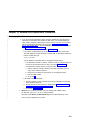
http://www.hursley.ibm.com/ssa/
This web page provides links to SSA publications and other web pages,
including the other web page in this list.
|
|
|
|
http://www.hursley.ibm.com/ssa/rs6k/
This web page contains a list of the latest levels of SSA support microcode,
and provides a microcode download capability for the RS/6000 and AIX
environments.
|
Numbering Convention
In this book:
KB means 1 000 bytes.
MB means 1 000 000 bytes.
GB means 1 000 000 000 bytes.
xvi
Advanced SerialRAID Adapters User and Maintenance Information
Part 1. User Information
1
2
Advanced SerialRAID Adapters User and Maintenance Information
Chapter 1. Introducing SSA and the Advanced SerialRAID Adapters
This chapter describes:
v Serial storage architecture (SSA).
|
|
|
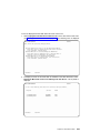
|
|
|
v The Advanced SerialRAID Adapter and the Advanced SerialRAID Plus Adapter.
Physically, the two types of adapter are the same. The Advanced SerialRAID Plus
Adapter, however, provides additional functions.
In this book, the name “Advanced SerialRAID Adapter” is used both for the Advanced
SerialRAID Adapter and for the Advanced SerialRAID Plus Adapter, unless otherwise
stated.
Serial Storage Architecture (SSA)
Serial Storage Architecture (SSA) is an industry-standard interface that provides
high-performance fault-tolerant attachment of I/O storage devices. In SSA subsystems,
transmissions to several destinations are multiplexed; the effective bandwidth is further
increased by spatial reuse of the individual links. Commands are forwarded
automatically from device to device along a loop until the target device is reached.
Multiple commands can be travelling around the loop simultaneously. SSA retains the
SCSI-2 commands, queuing model, and status and sense bytes.
3
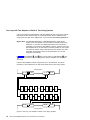
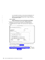
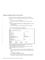
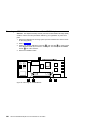
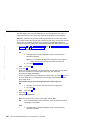
The Advanced SerialRAID Adapters (type 4–P)
|
|
|
|
|
|
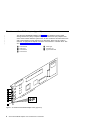
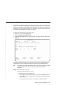
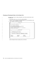
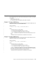
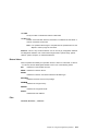
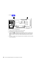
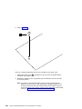
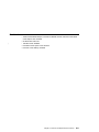
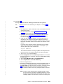
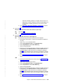
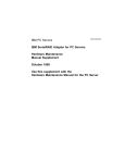
The Advanced SerialRAID Adapters (see Figure 1) are 40-MB-per-second Serial
Storage Architecture (SSA), Peripheral Component Interconnect (PCI) adapters that
serve as the interface between systems that use PCI architecture and devices that use
SSA. These adapters provide support for two SSA loops. Each loop can contain a
maximum of eight pairs of adapter connectors and a maximum of 48 disk drives. See
also “Rules for SSA Loops” on page 22.
1
2
3
4
5 Green light
6 Connector A1
7 Type-number label
Connector B2
Green light
Connector B1
Connector A2
1
2
3
4
5
6
4-P
7
Figure 1. An Advanced SerialRAID Adapter Card (Type 4–P)
4
Advanced SerialRAID Adapters User and Maintenance Information
Note: In the SSA service aids, this adapter is called “IBM SSA 160 SerialRAID Adapter
(14109100)”.
The adapter card has four SSA connectors that are arranged in two pairs. Connectors
A1 and A2 are one pair; connectors B1 and B2 are the other pair.
The SSA links must be configured as loops. Each loop is connected to a pair of
connectors at the SSA adapter card. These connectors must be a valid pair (that is, A1
and A2 or B1 and B2); otherwise, the disk drives on the loop are not fully configured,
and the diagnostics fail. Operations to all the disk drives on a particular loop can
continue if that loop breaks at any one point.
This adapter also contains array management software that provides RAID functions to
control the arrays of the RAID subsystem (see also “Chapter 3. RAID Functions and
Array States” on page 29). An array can contain several member disk drives. Each
array is handled as one disk by the operating system. The array management software
translates requests to this disk into requests to the member disk drives. Although this
adapter is a RAID adapter, it can be configured so that all, some, or none of the disk
drives that are attached to it are member disk drives of arrays.
The Advanced SerialRAID Adapter can be connected, by way of one or two SSA loops,
to other SSA adapters. These adapters can be either in the same using system, or in
separate using systems. (See “Rules for SSA Loops” on page 22 for details of valid
configurations.)
Fast-Write Cache Feature
|
|
|
|
An optional 32 MB Fast-Write Cache feature is available for the Advanced SerialRAID
Adapter. This feature improves performance for jobs that include many write operations.
128 MB Memory Module Feature
An optional 128 MB dual inline memory module (DIMM) feature is available. This
feature is recommended for two-way fast-write operations.
Chapter 1. Introducing SSA and the Advanced SerialRAID Adapters
5
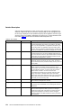
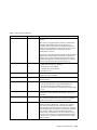
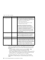
Lights of the Advanced SerialRAID Adapters
Each pair of connectors has a green light that indicates the operational status of its
related loop:
Status of Light Meaning
Off
Both SSA connectors are inactive. If disk drives or other SSA
adapters are connected to these connectors, either those disk drives
or adapters are failing, or their SSA links are not active.
Permanently on
Both SSA links are active (normal operating condition).
Slow Flash
Only one SSA link is active.
Port Addresses of the Advanced SerialRAID Adapters
The port addresses used in some SRNs that relate to these adapters can be numbers 0
through 3. They correspond to the port connectors on the SSA adapter:
0
1
2
3
=
=
=
=
Connector
Connector
Connector
Connector
A1
A2
B1
B2
SSA Adapter ID during Bring-Up
All adapters that can be used on RISC using systems generate a three-digit
configuration program indicator number. During system bring-up, this indicator number
appears on the three-digit display of the using system. The numbers are:
80C
6
Advanced SerialRAID Adapter (type 4-P) is being identified or configured.
Advanced SerialRAID Adapters User and Maintenance Information
Chapter 2. Introducing SSA Loops
This chapter describes the principles of SSA loops, how SSA devices are known to the
system programs, and the rules that you must observe when you configure your SSA
loops.
Loops, Links, and Data Paths
In the simplest SSA configuration, SSA devices are connected through two or more
SSA links to an SSA adapter that is located in a using system. The devices, SSA links,
and SSA adapter are configured in loops. Each loop provides a data path that starts at
one connector of the SSA adapter and passes through a link (SSA cable) to the
devices. The loop continues through the devices, then returns through another link to a
second connector on the SSA adapter.
The maximum permitted length for an external copper cable that connects two SSA
nodes (for example, disk drives) is 25 meters (82 feet).
The maximum permitted length for an external fiber optic cable that connects two SSA
nodes (for example, disk drives) is 10 kilometers (32800 feet). Some devices, however,
can operate only at shorter distances. See your subsystem documentation for details.
Details of the rules for configuring SSA loops are given for each SSA adapter in “Rules
for SSA Loops” on page 22.
7
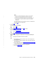
Simple Loop
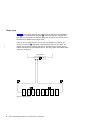
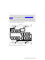
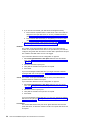
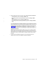
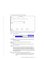
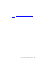
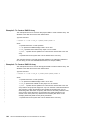
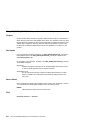
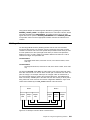
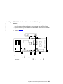
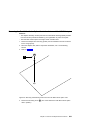
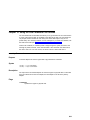
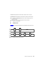
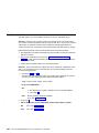
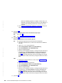
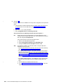
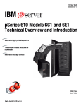
Figure 2 shows a simple SSA loop. The devices that are attached to the SSA adapter
card 1 are connected through SSA links 2. These SSA links are configured as a
loop. Data and commands to a particular device pass through all other devices on the
link between the adapter and the target device.
Data can travel in either direction round the loop. The adapter can, therefore, get
access to the devices 3 (disk drives in this example) through two data paths. The
adapter always, however, uses the path that has the fewest interconnecting devices
between the adapter and the destination device. The using system cannot detect which
data path is being used.
|
|
|
Using system
A1 A2
B1 B2
Disk
Disk
Disk
Disk
Disk
Disk
Disk
Disk
1
2
3
4
5
6
7
8
Figure 2. Simple Loop
8
Advanced SerialRAID Adapters User and Maintenance Information
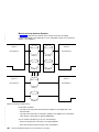
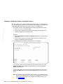
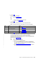
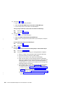
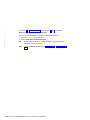
Simple Loop — One Disk Drive Missing
|
|
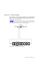
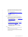
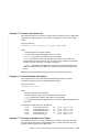
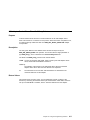
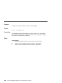
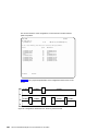
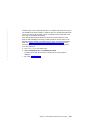
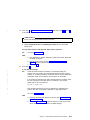
If a disk drive fails, or is switched off, the loop is broken, and one of the data paths to a
particular disk drive is no longer available. The disk drives on the remainder of the loop
continue to work, but an error is reported to the system. The adapter now uses the
alternative path to some of the devices.
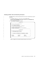
In Figure 3, disk drive number 3 has failed. Disk drives 1 and 2 can communicate with
the using system only through connector A1 of the SSA adapter. Disk drives 4 through
8 can communicate only through connector A2 of the SSA adapter.
Using system
A1 A2
B1 B2
Disk
Disk
Disk
Disk
Disk
Disk
Disk
Disk
1
2
3
4
5
6
7
8
Figure 3. Simple Loop with One Disk Drive Missing
Chapter 2. Introducing SSA Loops
9
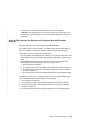
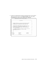
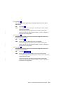
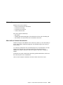
Simple Loop — Two Disk Drives Missing
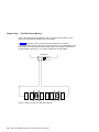
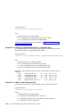
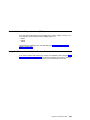
If two or more disk drives are switched off, fail, or are removed from the loop, some
disk drives might become isolated from the SSA adapter.
In Figure 4, disk drives 3 and 7 have been removed. Disk drives 1 and 2 can
communicate with the using system only through connector A1 of the SSA adapter. Disk
drive number 8 can communicate with the using system only through connector A2 of
the SSA adapter. Disk drives 4, 5, and 6 are isolated from the SSA adapter.
Using system
A1 A2
B1 B2
Disk
Disk
Disk
Disk
Disk
Disk
Disk
Disk
1
2
3
4
5
6
7
8
Figure 4. Simple Loop with Two Disk Drives Missing
10
Advanced SerialRAID Adapters User and Maintenance Information
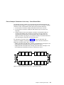
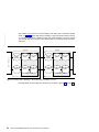
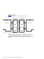
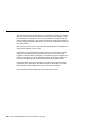
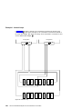
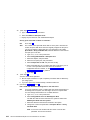
One Loop with Two Adapters in One Using System
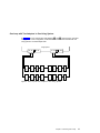
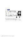
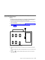
In Figure 5, the loop contains two SSA adapters 1 and 2 that are both in the same
using system. In this configuration, all the disk drives can still communicate with the
using system if one SSA adapter fails.
Using System
A1 A2
1
B1 B2
A1 A2
2
B1 B2
Disk
Disk
Disk
Disk
Disk
Disk
Disk
Disk
16
15
14
13
12
11
10
9
Disk
Disk
Disk
Disk
Disk
Disk
Disk
Disk
1
2
3
4
5
6
7
8
Figure 5. One Loop with Two Adapters in One Using System
Chapter 2. Introducing SSA Loops
11
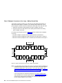
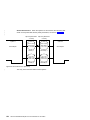
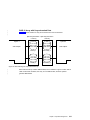
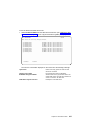
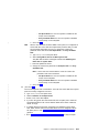
One Loop with Two Adapters in Each of Two Using Systems
If the loop contains four SSA adapters, with two adapters in each of two using systems,
disk drives become isolated if they are connected between the two adapters of one
using system, and both those adapters fail, or are held reset, but remain powered on.
Bypass Note: Your SSA Disk Subsystem, or SSA Disk Enclosure, might contain
bypass cards. Each bypass card can switch the internal strings of the
subsystem, or enclosure, if it detects that neither of its connectors is
connected to a powered-on SSA adapter or device. Therefore, if the two
SSA adapters fail, or are held reset, but remain powered on, the bypass
card does not operate, and the disk drives become isolated. (For more
information about bypass cards, see the publications for your disk
subsystem or enclosure.)
In Figure 6, SSA adapters 1 and 2 are in using system 1; SSA adapters 3 and
4 are in using system 2. In each using system, the two adapters are connected to
each other.
If the two SSA adapters of either using system fail, or are held reset, but remain
powered on, all the disk drives can still communicate with the other using system.
Using System 1
A1 A2
1
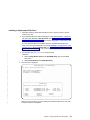
B1 B2
A1 A2
2
B1 B2
Disk
Disk
Disk
Disk
Disk
Disk
Disk
Disk
16
15
14
13
12
11
10
9
Disk
Disk
Disk
Disk
Disk
Disk
Disk
Disk
1
2
3
4
5
6
7
8
B2 B1
3
A2 A1
B2 B1
4
A2 A1
Using System 2
Figure 6. One Loop, Two Adapters in Each of Two Using Systems
12
Advanced SerialRAID Adapters User and Maintenance Information
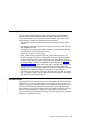
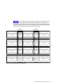
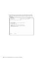
If, however, disk drives are connected into the link between two SSA adapters that are
in the same using system, those disk drives become isolated if both SSA adapters fail,
or are held reset, but remain powered on (see also “Bypass Note” on page 12). In
Figure 7, disk drives 13 through 16 have been connected between the SSA adapters in
using system 1. If both adapters fail, or are held reset, but remain powered on, disk
drives 1 through 12 can still communicate with using system 2. Disk drives 13 through
16, however, cannot communicate with using system 2, because their data paths are
through the adapters in using system 1. When using system 1 is rebooted, disk drives
13 through 16 remain unavailable for a long time.
Using System 1
A1 A2
1
B1 B2
A1 A2
Disk
Disk
Disk
Disk
16
15
14
13
2
B1 B2
Disk
Disk
Disk
Disk
12
11
10
9
Disk
Disk
Disk
Disk
Disk
Disk
Disk
Disk
1
2
3
4
5
6
7
8
B2 B1
3
A2 A1
B2 B1
4
A2 A1
Using System 2
Figure 7. Disk Drives Isolated by Failing Using System
Chapter 2. Introducing SSA Loops
13
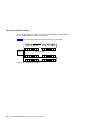
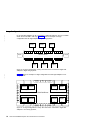
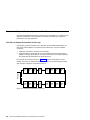
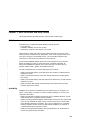
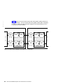
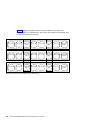
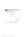
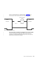
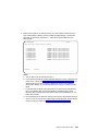
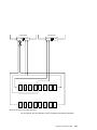
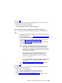
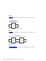
Two Loops with One Adapter
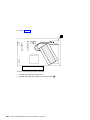
If only one SSA adapter is contained in the SSA loops, the adapter can provide support
for up to 96 disk drives (a maximum of 48 per loop).
Figure 8 shows an example configuration that has two loops and one adapter:
Adapter
SSA Disk Drives
Figure 8. Two Loops with One Adapter
14
Advanced SerialRAID Adapters User and Maintenance Information
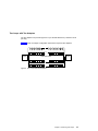
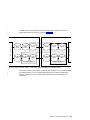
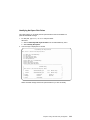
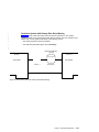
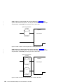
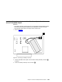
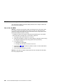
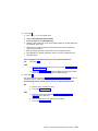
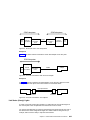
Two Loops with Two Adapters
The two adapters can provide support for up to 96 SSA disk drives (a maximum of 48
per loop).
Figure 9 shows an example configuration that has two loops and two adapters:
Adapter
SSA Disk Drives
Adapter
Figure 9. Two Loops with Two Adapters
Chapter 2. Introducing SSA Loops
15
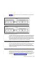
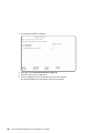
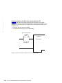
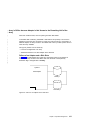
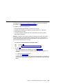
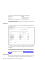
Large Configurations
|
|
|
|
Up to eight SSA adapters can be connected in a particular SSA loop, and up to 48 disk
drives can be included in that loop. Figure 10 shows an example of a large
configuration that has eight adapters in eight using systems.
Adapter
Adapter
Adapter
Adapter
Adapter
SSA Disk Drives
Adapter
Adapter
Adapter
Figure 10. A Large Configuration of Thirty-Two Disk Drives Connected to Eight SSA
Adapters in Eight Using Systems
|
|
|
Figure 11 shows an example of a large configuration that has eight adapters in four
using systems.
Adapter
Adapter
Adapter
Using System A
Adapter
Using System B
SSA Disk Drives
Using System C
Adapter
Adapter
Using System D
Adapter
Adapter
Figure 11. A Large Configuration of Thirty-Two Disk Drives Connected to Eight SSA
Adapters in Four Using Systems,
16
Advanced SerialRAID Adapters User and Maintenance Information
|
Switching Off Using Systems
Be careful if you want to switch off one or more using systems in a large configuration.
If any disk subsystem in the configuration does not use bypass cards, some using
systems might lose access to disk drives if you:
v Switch off more than one using system at a time
v Switch off a using system when a disk drive has failed.
Note: For more information about bypass cards, see the publications for your disk
subsystems or enclosures.
Switching On Using Systems
When you switch on using systems of a large configuration, ensure that each using
system configures all the disk drives in the SSA loop. You can switch on each using
system and give the cfgmgr command to ensure that all the disk drives are configured.
If, however, you need your pdisk assignments to be constant between using systems,
follow the procedures given in “Configuring Devices on an SSA Loop” on page 18.
Chapter 2. Introducing SSA Loops
17
Configuring Devices on an SSA Loop
If an SSA loop contains three or more SSA adapters that are installed in two or more
using systems, you must ensure that all those using systems are switched on, and that
all the disk drives in all those using systems are configured, as follows:
|
|
|
|
|
|
v If all the using systems are switched off (Micro Channel or PCI):
1. For each Micro Channel system:
a. Set Secure mode on each using system.
b. Switch on all the using systems.
c. Wait for 200 to be displayed on the operator panel of each system.
|
|
|
|
|
|
|
|
|
|
|
|
|
For each PCI system:
a. Switch on one using system only.
b. Wait for the first display (logo) to appear on the screen. Press F1
immediately. The using system goes into System Management Services
mode.
2. When each using system is in the state described in the preceding steps:
– For Micro Channel systems, set Normal mode to continue the boot process.
– For PCI systems, press F10 (Exit) to continue the boot process.
v If one or more using systems are switched on (Micro Channel or PCI):
1. Switch on the remaining using systems.
2. On each using system:
a. Run the cfgmgr command to configure all the disk drives.
b. Manually vary on the volume groups and mount the file systems as required.
|
SSA Link Speed
Some SSA devices can run at 20 MB per second; others can run at 40 MB per second.
Both types of devices can exist in a particular configuration, but for best performance all
links should run at the same speed. Two types of SSA cable are available:
v 20 MB per second SSA cables (color coded black)
v 40 MB per second SSA cables (color coded blue).
The speed at which a link runs is automatically agreed between its two nodes. Under
some fault conditions, a link that normally runs at 40 MB per second might run at
20 MB per second. The automatic run_ssa_link_speed diagnostic searches for pairs
of 40-MB-per-second nodes that are running at only 20 MB per second. This diagnostic
is started by an entry in the cron table. If you are using 20-MB-per-second cables to
connect 40-MB-per-second SSA nodes, delete the run_ssa_link_speed entry from the
cron table. This action prevents the logging of errors that can be solved only by the
installation of 40-MB-per-second cables.
18
Advanced SerialRAID Adapters User and Maintenance Information
Identifying and Addressing SSA Devices
This section describes how SSA adapters and devices are known to the using system
programs.
Location Code Format
Location codes identify the locations of adapters and devices in the using system and
its attached subsystems and devices. These codes are displayed when the diagnostic
programs isolate a problem. For information about the location codes that are used by
the using system, see the Operator Guide for the using system.
A B - CD - E F - GH
Unused
Unused
Unused
P = Physical disk drive
L = Logical disk drive
Adapter position
(number of the slot, 1 through 8,
containing the SSA adapter)
System I/O bus identifier
Expansion adapter position
Expansion drawer
The location code shows only the position of the SSA adapter in the using system and
the type of device that is attached. The location of the device within the SSA loop must
be found by use of a service aid. The service aids use the IEEE-standard 16-digit
unique ID of the device.
Pdisks, Hdisks, and Disk Drive Identification
The physical disk drives (pdisks) in an SSA subsystem can be configured as logical
units (LUNs). A LUN is also known as an hdisk, and can consist of one or more
physical disk drives. An hdisk in an SSA subsystem might, therefore, consist of one
pdisk or several pdisks.
The configuration software allocates an identification (hdisk and pdisk number) to each
disk drive during the configuration of the SSA link. The disk drives do not have fixed
physical addresses.
The numeric identifiers of pdisks, hdisks, and the disk drive slots are not related to each
other. For example, pdisk1 is not necessarily in slot 1 of the physical unit in which it is
installed.
Chapter 2. Introducing SSA Loops
19
The configuration software first recognizes the disk drive by its machine-readable serial
number. The serial number of the disk drive is also displayed by the service aids. The
service aids show the number as the last eight digits of the IEEE SSA Unique ID.
Service actions are always related to physical disk drives. For this reason, errors that
occur on SSA disk drives are always logged against the physical disk drive (pdisk).
If a disk drive that has been formatted on a machine of a particular type (for example, a
Personal System/2) is later installed into a using system that is of a different type (for
example, an RS/6000), that disk drive is configured only as a pdisk during the
configuration of the using system.
20
Advanced SerialRAID Adapters User and Maintenance Information
SSA Unique IDs
Each SSA device has a specific identifier that is not used by any other SSA device in
the whole world. This identifier is called the IEEE SSA Unique ID (UID) of the device. It
is written into the device during manufacture.
The full UID consists of 16 characters. The label on the side of a disk drive shows the
full UID. The label on the front of a disk drive shows the serial number of the disk drive.
The serial number is actually part of the UID. Also part of the UID, the Connection
Address consists of the LUN name and the device-type identifier. The software uses
this information to access the device.
Full UID
Disk drive serial number
Connection Address
0000XXXXXXNNNNNN
XXNNNNNN
XXXXXXNNNNNNLLD
where:
XXXXXX
NNNNNN
LL
D
=
=
=
=
IEEE Organization Identifier (manufacturer)
Product / ID (assigned unique number)
LUN (always 00 for a LUN device)
Device type:
(D for an SSA Physical disk drive)
(E for a fast-write logical disk)
(F for a RAID-0 array)
(K for a RAID-5 array)
You might need to know the UID of a disk drive if you want to use the mkdev
command to give that disk drive a specific hdisk number.
Chapter 2. Introducing SSA Loops
21
|
|
Rules for SSA Loops
|
|
|
|
|
|
|
|
|
|
|
|
|
For SSA loops that include an Advanced SerialRAID Adapter (type 4–P), the following
rules apply:
|
|
|
|
|
|
|
|
|
|
|
|
|
|
|
Table 1. Number of Adapters that are Supported in an SSA Loop
v Each SSA loop must be connected to a valid pair of connectors on the SSA adapter
(that is, either connectors A1 and A2, or connectors B1 and B2).
v A maximum of one pair of adapter connectors can be connected in a particular SSA
loop.
v All member disk drives of an array must be on the same SSA loop.
v A maximum of 48 SSA devices can be connected in a particular SSA loop.
v When an SSA adapter is connected to two SSA loops, and each loop is connected to
other adapters, all adapters must be connected to both loops.
v The number of adapters that are supported in an SSA loop is determined by whether
any disk drives are configured for RAID or fast-write operations, and by the type of
adapter (see Table 1).
Array Type
Non-RAID
Number of
Adapters in
Loop
8
Type of Adapters Allowed
Advanced SerialRAID Adapter
PCI SSA Multi-Initiator/RAID EL Adapter
Micro Channel SSA Multi-Initiator/RAID EL Adapter
RAID-0
1
Advanced SerialRAID Adapter
RAID-1
2
Advanced SerialRAID Adapter at microcode level above 50
RAID-5
2
Advanced SerialRAID Adapter
PCI SSA Multi-Initiator/RAID EL Adapter
Micro Channel SSA Multi-Initiator/RAID EL Adapter
|
|
|
|
RAID-10
2
Advanced SerialRAID Adapter at microcode level above 50
Fast-Write
1
Advanced SerialRAID Adapter at microcode level below 50
2
Advanced SerialRAID Adapter at microcode level above 50
See the SSA Adapters: User’s Guide and Maintenance Information manual,
SA33-3272 (Version 01 or above) for more information about the level of code that is
required in the Micro Channel SSA Multi-Initiator/RAID EL Adapter (type 4–M) or the
PCI SSA Multi-Initiator/RAID EL Adapter (type 4–N).
|
22
Advanced SerialRAID Adapters User and Maintenance Information
Checking the Level of the Adapter Microcode
If you need to check the level of the adapter microcode:
1. Type, on the command line:
lscfg -vl ssan
where ssan is the name of the adapter whose microcode you are checking; for
example, ssa0.
A list of vital product data (VPD) is displayed.
2. Find ROS Level and ID. The first two characters of this field show the level of the
adapter microcode. For example, 50nn (where n is a digit 0 through 9) shows a
microcode level of 50.
Chapter 2. Introducing SSA Loops
23
Rules for the Physical Relationship between Disk Drives and Adapters
The physical relationship between the disk drives and the adapters in an SSA loop can
affect the performance of the subsystem. The following rules help you to get best
performance from your subsystem.
One Pair of Adapter Connectors in the Loop
The following sequence enables you to determine the best relationship between the
disk drives and the adapter on an SSA loop that contains only one pair of adapter
connectors.
1. Determine which data is accessed most frequently.
2. Assign that data to those disks drives that are farthest (round the loop) from the
adapter connectors. By doing this, you prevent the activity of the busiest disk drive
from obstructing the data path to the other disk drives.
For example, the loop that is shown in Figure 12 contains 16 disk drives, and the
adapter connectors are between disk drives 1 and 16. The most-frequently-accessed
data, therefore, should be on disk drives 8 and 9.
Disk
2
Disk
3
Disk
4
Disk
5
Disk
6
Disk
7
Disk
8
Disk
16
Disk
15
Disk
14
Disk
13
Disk
12
Disk
11
Disk
10
Disk
9
Adapter
Disk
1
Figure 12. One Pair of Connectors in the Loop
24
Advanced SerialRAID Adapters User and Maintenance Information
Pairs of Adapter Connectors in the Loop – Some Shared Data
The following sequence enables you to determine the best relationship between the
disk drives and the adapter on an SSA loop that contains two or more pairs of adapter
connectors. Some of the disk drives share data access with other disk drives.
1. For each pair of connectors, identify all the data that the loop is to access.
2. For each pair of connectors, identify the data that the loop is to access most
frequently.
3. Assign the data for each pair of adapter connectors to the disk drives that are
connected immediately next to the pair of connectors in the loop. Assign the
most-frequently-accessed data to those disk drives that are farthest from the
adapter connectors. By doing this, you prevent the activity of the busiest disk drive
from obstructing the data path to the other disk drives.
For example, the loop that is shown in Figure 13 contains 16 disk drives. The
connectors of adapter A are between disk drives 1 and 16, and the connectors of
adapter B are between disks 8 and 9. Therefore:
v Adapter A should access disk drives 1 through 4 and disk drives 13 through 16. The
most-frequently-accessed data should be on disk drives 4 and 13.
v Adapter B should access disk drives 5 through 8 and disk drives 9 through 12. The
most-frequently-accessed data should be on disk drives 5 and 12.
Disk
2
Disk
3
Disk
4
Disk
5
Disk
6
Disk
7
Disk
8
Disk
16
Disk
15
Disk
14
Disk
13
Disk
12
Disk
11
Disk
10
Disk
9
Adapter A
Adapter B
Disk
1
Figure 13. Pairs of Connectors in the Loop – Some Shared Data
Chapter 2. Introducing SSA Loops
25
Pairs Of Adapter Connectors in the Loop – Mainly Shared Data
The following sequence enables you to determine the best relationship between the
disk drives and the adapter, or adapters, on an SSA loop that contains two or more
pairs of adapter connectors. Most of the disk drives share data access with each other.
1. Determine which data is shared between the pairs of adapter connectors.
2. Assign this data to the disk drives that are equally spaced between the sharing
pairs of adapter connectors.
For example, the loop that is shown in Figure 14 contains 16 disks and four adapters.
In this loop:
v The pairs of adapter connectors should be spaced between the disk drives.
v Data that is shared by adapters A and B should be put onto disk drives 1 through 4.
v Data that is shared by adapters B and C should be put onto disk drives 5 through 8.
Adapter B
Disk
2
Disk
3
Disk
4
Disk
5
Disk
6
Disk
7
Disk
8
Disk
16
Disk
15
Disk
14
Disk
13
Disk
12
Disk
11
Disk
10
Disk
9
Adapter A
Adapter C
Disk
1
Adapter D
Figure 14. Pairs of Connectors in the Loop – Mainly Shared Data
Note: For configurations such as that shown here, we recommend that the adapters be
installed in separate using systems. Otherwise, disk drives can become isolated
should both adapters fail, or be held reset, in one of the using systems. See
“One Loop with Two Adapters in One Using System” on page 11 and “One Loop
with Two Adapters in Each of Two Using Systems” on page 12 for more
information.
If two using systems are switched off, disk drives can become isolated if the
SSA subsystem does not have bypass cards (see “Bypass Note” on page 12). If
more than one using system is rebooted at the same time, disk drives can
become isolated while the boot is running.
26
Advanced SerialRAID Adapters User and Maintenance Information
Reserving Disk Drives
The Advanced SerialRAID Adapter, the Micro Channel SSA Multi-Initiator/RAID EL
Adapter, and the PCI SSA Multi-Initiator/RAID EL Adapter implement reservation by
using commands that are sent directly from adapter to adapter. They do not use the
SCSI reservation command. The advantages of this method are:
v The AIX Physical Volume ID (PVID) can be read from a reserved drive by system
software.
v It is possible to determine which adapter is holding a reservation to a disk using the
ssa_rescheck command.
v The diagnostics can detect particular failure conditions on reserved drives that they
cannot detect with the other reservation method.
v Fencing can be used on a reserved disk.
v Node_number locking is supported. With node_number locking, the drive is not
locked to an adapter, but rather to a using system. To do this, each using system in
an SSA network must have a unique node number. The node number is stored as
the node_number attribute of ssar. It can be queried with the lsattr command and set
by using the chdev command. The ssavfynn command (described in “ssavfynn
Command” on page 318) can be used to verify that no duplicate node numbers exist.
v If a reservation is challenged (that is, a node that does not hold the reservation
attempts to access a reserved SSA logical disk), the adapter verifies that a valid path
still exists to the node that is holding the reservation. If no path exists, the
reservation is removed, and the new node is allowed access to the disk. This means
that, if an adapter is used to reserve a disk and is then disconnected or powered off,
that disk becomes effectively unreserved.
|
|
|
|
|
|
|
|
|
|
Fast-Write Cache
SSA adapters that are on SSA loops of up to two SSA adapters can use the Fast-Write
cache feature. For a two-way configuration, the two adapters can be in the same, or in
different, using systems. Fast-write functions can be enabled for single disk drives or for
RAID arrays. Performance improvements are related to the type of disk drive (single
disk or RAID array type) and the workload. If two-way fast-write functions are used in a
two-host system configuration, the performance improvements are greater when
concurrent access is not permitted to disk drives. When concurrent access is permitted,
performance improvements are less.
Chapter 2. Introducing SSA Loops
27
28
Advanced SerialRAID Adapters User and Maintenance Information
Chapter 3. RAID Functions and Array States
This chapter describes the RAID functions and the states of RAID arrays.
RAID Functions
Redundant Array of Independent Disks (RAID) technology provides:
v Larger disk size
v Immediate availability and recovery of data
v Redundancy of data at a level that you can choose.
RAID technology stores data across groups of disk drives that are known as arrays.
These arrays are contained in array subsystems, which can be configured with one or
more arrays. All arrays, except RAID-0 arrays, can provide data redundancy that
ensures that no data is lost if one disk drive in the array fails.
|
|
|
|
An Advanced SerialRAID Adapter, which uses microcode below level 50, provides
RAID-0 and RAID-5 functions to control the arrays of the RAID subsystem. An
Advanced SerialRAID Plus Adapter, which uses microcode at or above level 50,
provides RAID-0, RAID-1, RAID-5, and RAID-10 functions.
|
|
|
|
|
|
|
|
|
The main characteristics of the various RAID types are as follows:
|
|
|
|
|
|
|
|
|
|
|
v RAID-0 provides data striping across disk drives, but provides no added protection
against loss of data.
v RAID-1 provides data mirroring across two member disk drives to protect against
loss of data.
v RAID-5 provides data striping with parity data across disk drives to provide protection
against loss of data.
v RAID-10 provides data striping and data mirroring across disk drives to provide
protection against loss of data.
Availability
Availability is an important consideration that can affect the way you configure your
arrays. It is the ability of a system to continue operating, although one or more of its
components have failed.
v RAID-0 provides data availability equivalent to that of a standard disk drive, but with
better performance for long data transfer operations.
v RAID-1 provides good data availability because data is mirrored on two member disk
drives, as it is with RAID-10. RAID-1 arrays, however, have only two member disk
drives. Member disk drives of a RAID-1 array can be configured to be in separate
domains. Separate domains ensure that data remains available if, for example, a
complete domain fails through loss of power.
v RAID-5 provides good data availability with good performance for workloads that
include many read and write operations.
29
v RAID-10 provides good data availability and performance that is better than that
provided by RAID-5, especially when a member disk drive has failed. For long data
transfer operations, performance is better than that provided by RAID-1 because data
is striped across member disk drives. For short data transfer operations, performance
is better because operations are distributed across the member disk drives, and the
effect of skew is reduced. Member disk drives of a RAID-10 array can be configured
to be in separate domains. Separate domains ensure that data remains available if,
for example, a complete domain fails through loss of power.
|
|
|
|
|
|
|
|
Disk Drives That Are Not in Arrays
Disk drives that are connected to an SSA RAID adapter do not need to be members of
an array. The SSA RAID adapter handles such disk drives in the same way as a
non-RAID SSA adapter does. It transfers data directly between the disk drives and the
system, and uses no RAID functions.
When first installed, all disk drives are, by default, defined as AIX disks; that is, they are
not members of an array. Before they can be added to arrays, you must redefine them
so that the system no longer has direct access to them.
30
Advanced SerialRAID Adapters User and Maintenance Information
RAID-0 Array States
A RAID-0 array can be in either of two states. A knowledge of those states is useful
when you are configuring your arrays. The states are described here.
Good State
A RAID-0 array is in the Good state when all the member disk drives of that array are
present.
Offline State
A RAID-0 array enters Offline state when one or more member disk drives become
missing. Read and write operations are not allowed.
Chapter 3. RAID Functions and Array States
31
|
|
RAID-1 Array States
|
|
RAID-1 array states are the same as RAID-10 array states. For details, see “RAID-10
Array States” on page 36.
|
|
|
|
|
|
|
|
In RAID-1 arrays, the first member disk drive of the array is defined as the primary disk
drive and the second member disk drive is defined as the secondary disk drive. These
definitions prevent operation on separate member disk drives of the array when the
array becomes split, but separate systems can still access one of the member disk
drives. RAID-10 defines the first and third disk drives to be primary member disk drives.
RAID-1 defines the first disk drive to be the equivalent of the first and third disk drives
together. If the first disk drive is missing in RAID-1, it is equivalent to the first and third
disk drives being missing in RAID-10.
32
Advanced SerialRAID Adapters User and Maintenance Information
RAID-5 Array States
A RAID-5 array can be in one of several states. A knowledge of those states is useful
when you are configuring your arrays. The states are described here. A flowchart for the
RAID-5 array states is shown in Figure 15 on page 35.
Good State
A RAID-5 array is in the Good state when all the member disk drives of that array are
present.
Exposed State
A RAID-5 array enters the Exposed state when a member disk drive becomes missing
(logically or physically) from that array. When an array is in the Exposed state, you can
reintroduce the missing disk drive, or exchange it for a new one. If the missing disk
drive is reintroduced, the array returns to the Good state. The array management
software does not need to rebuild the data. If a new disk drive is exchanged for the
missing disk drive, the array management software rebuilds the data that was on the
original disk drive before it became missing, then writes that rebuilt data to the
replacement disk drive. When the data is correct, the array management software
returns the array to the Good state.
Read Operations while in the Exposed State
When a read operation is performed on an array that is in the Exposed state, the array
management software recreates the data that was contained on the missing disk drive.
On the Advanced SerialRAID Adapter, the array management software immediately
exchanges a hot spare disk drive for the missing disk drive, if a hot spare disk drive is
enabled and available when the read command is sent.
Write Operations while in the Exposed State
When a write command is sent to an array that is in the Exposed state, the array
management software does the following:
v If a hot spare disk drive is enabled and available when the write command is sent,
the array management software immediately exchanges the hot spare disk drive for
the missing disk drive, and returns the array to the Rebuilding state.
v If no hot spare disk drive is enabled and available, the first write operation causes
the array to enter the Degraded state. The written data is not protected. If the power
fails during a write operation, data might be lost (64 KB) unless the array is
configured to allow read-only operations while in the Exposed state. Most application
programs, however, cannot be run when write operations are not allowed.
Degraded State
A RAID-5 array enters the Degraded state if, while in the Exposed state, it receives a
write command. If a hot spare disk drive is available, the array management software
Chapter 3. RAID Functions and Array States
33
immediately exchanges the hot spare disk drive for the missing disk drive, and returns
the array to the Rebuilding state. If no hot spare disk drive is available, and a write
operation is performed on the array, the array remains in the Degraded state until you
take action to return that array to the Good state.
While in Degraded state, an array is not protected. If another disk drive in the array
fails, or the power fails during a write operation, data might be lost.
You can return the disk drive to the array, or install another disk drive by using the
procedure in step 32 on page 418 of MAP 2324: SSA RAID to logically add the device
to the array. The array management software starts a rebuilding operation to
synchronize the new disk drive with the data that is contained in the other disk drives of
the array. This action returns the array to the Good state.
Rebuilding State
A RAID-5 array enters the Rebuilding state when:
v That array is first created
v A member disk drive is replaced
v An adapter is replaced, but a correct shutdown has not been performed
Initial Rebuilding Operation
When an array is first created, it enters the Rebuilding state while parity is rebuilt. If a
disk drive fails during the initial rebuilding operation, no hot spare disk drive is
exchanged for the failing disk drive.
Disk Drive Replacement
An array enters Rebuilding state after a missing disk drive has been returned to the
array or exchanged for a replacement disk drive. When the array is in this state, all the
member disk drives are present, but the data and parity are being rebuilt on the
returned or replacement disk drive. The array management software allows read and
write operations on a disk drive that is in Rebuilding state. If the power fails before the
rebuilding is complete, the array management software restarts the complete rebuilding
operation when the power returns.
Adapter Replacement
If, for any reason, an adapter is exchanged for a replacement adapter, and a correct
shutdown has not been performed, the parity is rebuilt on all the associated arrays
when the replacement adapter powers on.
Offline State
A RAID-5 array enters Offline state when two or more member disk drives become
missing. Read and write operations are not allowed.
34
Advanced SerialRAID Adapters User and Maintenance Information
RAID-5 Array State Flowchart
Array Good
Disk
is removed
Disk fails
Array Exposed
Disk rejected
Second
disk fails or
is removed
Original disk
replaced
Y
N
N
Write operation
Array Offline
Y
New disk
Array Degraded
Array
enabled for
Hot Spare
N
Y
Hot Spare
available
N
Y
Hot Spare
swapped in
Allow
Write while
Exposed
Y
N
Array
Rebuilding
Write Op
rejected
Array Degraded
(no protection)
Figure 15. RAID-5 Array State Flowchart
Chapter 3. RAID Functions and Array States
35
|
|
RAID-10 Array States
|
|
|
Configuration information of the array is held in a reserved area sector on each of the
first three member disk drives of the array. If fewer than two of these sectors can be
read or written, the array normally goes into the Offline state.
|
|
|
|
|
|
|
|
|
|
|
|
|
|
|
|
|
|
|
|
|
|
|
An important characteristic of RAID-10 is that the mirrored pairs can be located in
different sites in different power domains. The availability of a RAID-10 array is,
therefore, better than that of RAID-5 array. However, if both domains of a two-site
configuration are both operational, but communication is lost between the sites, it is
important to ensure that each system does not continue to operate on its own copy of
the array. Under this condition the data might not be consistent. To prevent this problem
from occurring, the first, third, and fifth member disk drives of the array are the primary
members; the second, fourth, and sixth member disk drives are the secondary
members. Access to at least one of the primary disk drives that contain the
configuration information is normally required for array operations to continue.
Therefore:
|
|
A RAID-10 array can be in one of several states. A knowledge of those states is useful
when you are configuring your arrays. The states are described here.
|
v If a network partition exists, the using system that has access to the primary
configuration disk drives continues to operate. The using system that has access to
only the secondary configuration disk drives cannot normally access the array.
v If the using system fails at the site that contains the secondary member disk drive,
the using system that has access to the primary configuration disk drives continues
to operate.
v If the using system that has access to the primary configuration disk drives fails and
the primary configuration disk drives also fail, only the site that contains the
secondary configuration disk drives remains operational. Normally, the using system
that is at the secondary site is not allowed access to the array. To allow this using
system access to the array, the user must use the RAID array configurator to set a
flag that allows the using system to operate on only the secondary disk drives.
Good State
|
|
|
|
|
A RAID-10 array is in the Good state when:
|
|
|
The array is fully protected from the loss of multiple member disk drives if one copy of
the mirrored data is still available. Some unsynchronized records might still be under
repair.
v All the member disk drives of that array are present.
v No member disk drive is deconfigured.
v Read and write operations can be done on the array.
v No rebuilding operations need to be done.
36
Advanced SerialRAID Adapters User and Maintenance Information
|
Exposed State
|
|
|
|
|
A RAID-10 array is in the Exposed state when member disk drives are missing but still
configured. Read and write operations can be performed on the array, although write
operations put the array into the Degraded state. When the missing member disk drives
are reintroduced, the array returns to the Good state.
Degraded State
|
|
|
|
|
A RAID-10 array is in the Degraded state when one or more member disk drives are
missing or deconfigured, and a write operation has occurred. Read and write operations
can be performed on the array. The missing member disk drives are deconfigured so
that they are permanently excluded from the array. If they become available again, they
can be introduced only as new members.
|
|
|
A RAID-10 array is in the Degraded state also if the secondary half of the array
operates while the primary half is deconfigured. Under this condition, the secondary half
holds information about the members of the primary half to track recovery.
|
Rebuilding State
|
|
|
A RAID-10 array is in the Rebuilding state when a rebuilding operation is running on
one or more member disk drives. Read and write operations can be performed on the
array.
|
|
When an array is created, it enters the Rebuilding state to synchronize the member disk
drives. When the rebuilding operation is complete, the array returns to the Good State.
|
|
If the medium-error table fills during a rebuilding operation, the array remains in the
Rebuilding state until space becomes available in the table.
|
|
|
|
|
|
|
|
|
|
|
|
|
|
|
Offline State
A RAID-10 array can be in the Offline state for any of the following reasons:
v No NVRAM is available to operate the array.
v The array is split across SSA loops.
v All these three conditions exist:
– In the secondary half of the array, the member disk drive that contains the
configuration sector is present.
– In the primary half of the array, no members that hold configuration sectors are
present.
– The Split Array Resolution flag is not set.
v All these three conditions exist:
– In the primary half of the array, disk drive members that hold configuration sectors
are present.
– In the secondary half of the array, the member disk drive that contains the
configuration sector is not present.
Chapter 3. RAID Functions and Array States
37
|
|
|
|
|
|
|
|
– The Split Array Resolution flag is set.
v In the primary and secondary halves of the array, member disk drives that hold
configuration sectors are present, and the Split Array Resolution flag is set on the
secondary half. The array, however, was not initialized correctly.
v Two failures in a configuration update (configuration sectors, fence sector, label
sector, medium-error table, or unsync table).
v Both member disk drives of a mirrored pair are missing, deconfigured, or rebuilding.
Unknown State
|
|
|
|
|
|
|
|
|
|
A RAID-10 array is in the Unknown state when not enough array members are present
for the array configuration to be determined; that is, fewer than two of the first three
members are present. Unless the Split Array Resolution flag is set, the array enters the
Offline state to allow split arrays to operate if:
v The member disk drive that holds the configuration sector in the secondary half of
the array is available
and
v Neither of the member disk drives that hold configuration sectors in the primary half
of the array is available.
Multiple States
|
|
|
|
|
|
|
|
|
|
Different member disk drives of a RAID-10 array can be in different states. For
example, one mirrored pair might be rebuilding while, in a different pair, one member
disk drive is missing and the remaining member is in the Degraded state. A priority of
array states of the different members is used when the state of an array is reported
(highest priority first):
|
|
An error is logged whenever the state of an array changes, unless the state changes to
Good or Rebuilding.
1. Unknown
2. Offline
3. Exposed
4. Degraded
5. Rebuilding
38
Advanced SerialRAID Adapters User and Maintenance Information
Chapter 4. Using the SSA SMIT Menus
This chapter describes how to use the system management interface tool (SMIT) to
display and change characteristics of the SSA devices, and to access various service
functions. Three SSA menus are available through the SMIT Devices menu.
v SSA Adapter
v SSA Disks
v SSA RAID Arrays
Getting Access to the SSA Adapters SMIT Menu
1. For fast-path access to the SSA RAID Array SMIT menus, type smitty ssaa and
press Enter.
Otherwise:
a. Type smitty and press Enter. The System Management menu is displayed.
b. Select Devices. The Devices menu is displayed.
c. Select SSA Adapters.
2. The SSA Adapters menu is displayed:
|
|
|
|
|
|
|
|
|
|
|
|
|
|
|
|
|
|
|
|
|
|
|
|
|
|
SSA Adapters
Move cursor to desired item and press Enter.
List All SSA Adapters
Change/Show Characteristics of an SSA Adapter
Generate Error Report
Trace an SSA Adapter
Change/Show the SSA Node Number for this System
List All SSA Adapter Dumps
Copy an SSA Adapter Dump
F1=Help
F9=Shell
F2=Refresh
F10=Exit
F3=Cancel
Enter=Do
F8=Image
If you need help with an item, move the cursor to that item, and press F1 (Help).
39
Getting Access to the SSA Disks SMIT Menu
1. For fast-path access to the SSA RAID Array SMIT menus, type smitty ssad and
press Enter.
Otherwise:
a. Type smitty and press Enter. The System Management menu is displayed.
b. Select Devices. The Devices menu is displayed.
c. Select SSA Disks.
2. The SSA Disks menu is displayed:
SSA Disks
Move cursor to desired item and press Enter.
SSA Logical Disks
SSA Physical Disks
F1=Help
F9=Shell
F2=Refresh
F10=Exit
F3=Cancel
Enter=Do
F8=Image
Select the type of SSA disk on which you want to work.
v SSA logical disks are configured into the using system as hdisks. SSA hdisks
can be single disk drives or SSA RAID arrays.
v SSA physical disks are configured into the using system as pdisks. SSA pdisks
are used for service and configuration operations.
3. If you select SSA Logical Disks, go to step 4 on page 41.
If you select SSA Physical Disks, go to step 5 on page 41.
40
Advanced SerialRAID Adapters User and Maintenance Information
4. The SSA Logical Disks menu is displayed:
SSA Logical Disks
Move cursor to desired item and press Enter.
List All Defined SSA Logical Disks
List All Supported SSA Logical Disks
Add an SSA Logical Disk
Change/Show Characteristics of an SSA Logical Disk
Remove an SSA Logical Disk
Configure a Defined SSA Logical Disk
Generate Error Report
Trace an SSA Logical Disk
Show Logical to Physical SSA Disk Relationship
List Adapters Connected to an SSA Logical Disk
List SSA Logical Disks Connected to an SSA Adapter
Identify an SSA Logical Disk
Cancel all SSA Disk Identifications
Enable/Disable Fast-Write for Multiple Devices
F1=Help
F9=Shell
F2=Refresh
F10=Exit
F3=Cancel
Enter=Do
F8=Image
If you need help with an item, move the cursor to that item, and press F1 (Help).
5. The SSA Physical Disks menu is displayed:
SSA Physical Disks
Move cursor to desired item and press Enter.
List All Defined SSA Physical Disks
List All Supported SSA Physical Disks
Add an SSA Physical Disk
Change/Show Characteristics of an SSA Physical Disk
Remove an SSA Physical Disk
Configure a Defined SSA Physical Disk
Generate Error Report
Trace an SSA Physical Disk
Show Physical to Logical SSA Disk Relationship
List Adapters Connected to an SSA Physical Disk
List SSA Physical Disks Connected to an SSA Adapter
Identify an SSA Physical Disk
Cancel all SSA Disk Identifications
Show Connection Paths to an SSA Physical Disk
F1=Help
F9=Shell
F2=Refresh
F10=Exit
F3=Cancel
Enter=Do
F8=Image
If you need help with an item, move the cursor to that item, and press F1 (Help).
Chapter 4. Using the SSA SMIT Menus
41
Getting Access to the SSA RAID Arrays SMIT Menu
1. For fast-path access to the SSA RAID Array SMIT menus, type smitty ssaraid and
press Enter.
Otherwise:
a. Type smitty and press Enter. The System Management menu is displayed.
b. Select Devices. The Devices menu is displayed.
c. Select SSA RAID Arrays.
2. The SSA RAID Arrays menu is displayed:
|
|
|
|
|
|
|
|
|
|
|
|
|
|
|
|
|
|
|
|
|
|
|
|
|
|
|
|
|
|
SSA RAID Arrays
Move cursor to desired item and press Enter.
List All Defined SSA RAID Arrays
List All Supported SSA RAID Arrays
List All SSA RAID Arrays Connected to a RAID Manager
List Status Of All Defined SSA RAID Arrays
List/Identify SSA Physical Disks
List/Delete Old RAID Arrays Recorded in an SSA RAID Manager
List Status of Hot Spare Pools
List Status of Hot Spare Protection for an SSA RAID Array
List Components in a Hot Spare Pool
Add a Hot Spare Pool
Add an SSA RAID Array
Delete an SSA RAID Array
Change/Show Attributes of an SSA RAID Array
Change Member Disks in an SSA RAID Array
Change/Show Use of an SSA Physical Disk
Change Use of Multiple SSA Physical Disks
Change/Show/Delete a Hot Spare Pool
F1=Help
F9=Shell
F2=Refresh
F10=Exit
F3=Cancel
Enter=Do
F8=Image
For more information about how to use this menu, go to “Chapter 6. Using the RAID
Array Configurator” on page 55.
42
Advanced SerialRAID Adapters User and Maintenance Information
|
|
|
|
|
|
|
|
|
|
|
Chapter 5. Hot Spare Management
With all levels of adapter code, disk drives can be configured to be hot spare disk
drives. These hot spare disk drives can be used in any array that is on the same SSA
loop. If the adapter microcode level is at, or higher than, level 50, each hot spare disk
drive can be configured to a particular hot spare pool. The pdisks of arrays can also be
configured to hot spare pools. You can, therefore, control which hot spare disk drive is
to replace a particular failed member of an array. This chapter describes the ways in
which you can use hot spare pools.
Deciding how to Configure Hot Spare Disk Drive Pools
|
|
|
|
|
|
RAID-1 and RAID-10 arrays provide data protection by writing the same data to two
disk drives at the same time. You can provide more data protection if you put the two
disk drives into separate physical domains. These physical domains can be separate
SSA disk enclosures, separate power sources, or separate rooms or buildings. When
you use separate physical domains, you provide some capability to recover from an
unrecoverable loss of power.
|
|
|
|
For a RAID-1 or RAID-10 array to be able to recover after the failure of a physical
domain, at least one copy of the data must remain available. It is important, therefore,
that the action of replacing a failing disk drive with a hot spare disk drive does not
cause an array member to move to another physical domain.
43
|
|
|
|
|
Figure 16 shows an array that has its primary disk drives (pdisk2, pdisk3, pdisk10 and
pdisk11) in building 1, and its secondary disk drives (pdisk5, pdisk6, pdisk7 and pdisk8)
in building 2. Pdisk1 and pdisk4 have been assigned as hot spare disk drives, but no
hot spare pool has been defined.
Building 1
A
D
A
P
T
E
R
pdisk1
(Spare)
pdisk2
pdisk12
pdisk11
Building 2
pdisk3
pdisk10
pdisk4
(Spare)
pdisk5
pdisk9
pdisk8
Primary Disks
Figure 16. Primary Disks in Building 1; Secondary Disks in Building 2
44
Advanced SerialRAID Adapters User and Maintenance Information
pdisk6
A
D
A
P
T
E
R
pdisk7
Secondary Disks
|
|
|
If pdisk2 fails, the hot spare disk drive pdisk4 might replace pdisk 2 as one of the
primary disk drives in the array, as shown in Figure 17.
Building 1
A
D
A
P
T
E
R
Building 2
pdisk1
(Spare)
pdisk2
(Failed)
pdisk3
pdisk12
pdisk11
pdisk10
pdisk4
pdisk5
pdisk6
A
D
A
P
T
E
R
Primary Disks
pdisk9
pdisk8
pdisk7
Secondary Disks
Figure 17. Primary Disk in Building 1; Secondary Disks in Building 2; Distributed Spares
|
|
|
|
Now, assume that for some reason, the disk drives in building 2 are no longer available.
The example array is now in the Offline state because one of its four primary disk
drives is in building 2. Only the three primary disk drives that are in building 1 are
operational.
Chapter 5. Hot Spare Management
45
|
|
|
|
|
|
This problem can be solved if, in each building, a hot spare pool is created for the disk
drives. In Figure 18, all the disk drives in building 1 have been made members of pool
A1, and all the disk drives in building 2 have been made members of Pool A2. A failure
of a member disk drive in Pool A1 now causes pdisk1 to be selected as the hot spare
disk drive.
Building 1
Building 2
Pool A1
A
D
A
P
T
E
R
pdisk1
(Spare)
pdisk2
pdisk12
pdisk11
Pool A2
pdisk3
pdisk10
pdisk4
(Spare)
pdisk5
pdisk9
pdisk8
pdisk6
A
D
A
P
T
E
R
Primary Disks
pdisk7
Secondary Disks
Figure 18. Primary Disk in Building 1; Secondary Disks in Building 2; Pools
|
Hot spare pools can be configured in other ways, as shown in figures 19 through 21.
46
Advanced SerialRAID Adapters User and Maintenance Information
|
|
|
|
|
|
Figure 19 shows how RAID-5 arrays can be protected against the complete failure of an
SSA enclosure. Each pdisk of each array (hdisk) is in a different SSA enclosure. The
hot spare disk drives are also in a different enclosure. Pools A1 and A2 each contain an
hdisk and a hot spare disk drive. The pools ensure that, if any one SSA enclosure fails
completely, three disk drives are always available for each hdisk.
Enclosure-1
Pool A1
Pool A2
hdisk
hdisk
pdisk
pdisk
pdisk
pdisk
pdisk
pdisk
Spare
Spare
Enclosure-2
Enclosure-3
Enclosure-4
Figure 19. Pools and Hdisks across Enclosures
Chapter 5. Hot Spare Management
47
|
|
|
|
Figure 20 shows an alternative method of protecting RAID-5 arrays against the
complete failure of an SSA Enclosure. This method uses a different hot spare disk drive
to protect each member of the array.
Enclosure-1
hdisk
Pool A1
pdisk
Enclosure-2
pdisk
Spare
pdisk
Spare
pdisk
Spare
Pool A2
pdisk
Enclosure-3
Pool A3
pdisk
Figure 20. Pools along, and Hdisks across, Enclosures
48
hdisk
Advanced SerialRAID Adapters User and Maintenance Information
|
|
|
Figure 21 shows how a RAID-10 array can be protected against the complete failure of
an SSA enclosure.
Enclosure-1
Pool A1
hdisk1 Primary Disks
hdisk2 Primary Disks
spare
Enclosure-2
Pool A2
hdisk1 Secondary Disks
hdisk2 Secondary Disks
spare
Figure 21. Pools and Hdisks along Enclosures
|
|
|
|
|
|
|
|
|
|
|
|
|
|
|
|
|
|
|
|
The primary disk drives of the array are in enclosure 1; the secondary disk drives are in
enclosure 2. The secondary disk drives contain the same data as do the primary disk
drives. Pool A1 contains all the primary disk drives of the arrays and a hot spare disk
drive; pool A2 contains all the secondary disk drives and a hot spare disk drive. If one
enclosure fails completely, the other enclosure can still recover from a disk drive failure
because its disk drives and the hot spare disk drive are in the same pool.
Choosing How Many Hot Spare Disk Drives to Include in Each Pool
The number of hot spare disk drives that can be included in a hot spare pool is limited
only by the number of disk drives that are permitted on a single SSA loop. When
choosing how many disk drives to include in a hot spare pool, think about how many
disk drives the hot spare is protecting and how much time might elapse before a failed
disk drive can be replaced.
Choosing the Error Threshold (Alarm) Level for a Hot Spare Pool
Normally, a hot spare pool reports an error when any hot spare disk drive has been
used. Under some conditions, such as a disk drive failure at an unattended site, you
might prefer to delay service activities until more than one disk drive in a hot spare pool
has failed. You can do this when you create a hot spare pool. When you create a hot
spare pool (see “Adding a New Hot Spare Pool” on page 81), set the Hot Spare
Chapter 5. Hot Spare Management
49
|
|
|
|
|
|
Minimum parameter to be equal to the minimum number of hot spare disk drives that is
needed to protect the array in the selected pool. No error log entry is made until the
number of hot spare disk drives that remains in the pool is less than the Hot Spare
Minimum parameter.
Rules for Hot Spare Disk Drive Pools
v By default, all hot spare disk drives are in pool zero.
|
|
|
|
|
|
|
|
|
|
|
|
|
|
|
|
|
|
|
|
|
|
|
|
|
|
|
|
|
v Pool zero is called A0 for hot spare disk drives that are on SSA loop A, and B0 for
hot spare disk drives that are on SSA loop B.
v Hot spare pool numbers are in the range A0 through A31 and B0 through B31. The
pool number is automatically assigned when a hot spare pool is created.
v Arrays in pool zero can never use hot spare disk drives that are assigned to other
hot spare pools.
v Each pdisk can be assigned to a hot spare pool.
v Each member disk drive of a RAID array can be assigned to a different hot spare
pool.
v Disk drives can be added to a new pool only if they are in pool zero.
v If a disk drive is removed from a hot spare pool, that disk drive moves to pool zero.
v A hot spare pool can exist only on an SSA loop. For example, hot spare pool B1 on
adapter ssa0 has no physical or logical connection to hot spare pool B1 on adapter
ssa1.
v A hot spare pool can contain any number of hot spare disk drives. For instructions on
how to configure hot spare pools, see “Chapter 6. Using the RAID Array
Configurator” on page 55.
v If the Choose Hot Spare Only from Preferred Pool option is set to yes, hot spare
disk drives are selected only from the hot spare pool that contains the failing member
disk drive.
v If the Choose Hot Spare Only from Preferred Pool option is set to no, the selected
hot spare disk drive can be:
– A hot spare disk drive that is in the hot spare pool that contains the failing
member disk drive
– A hot spare disk drive that is in hot spare pool zero
– A hot spare disk drive that is in any other hot spare pool
v If more that one hot spare disk drive is available in a pool, and the hot spare disk
drives are of different sizes, the smallest appropriate disk drive is selected.
|
50
Advanced SerialRAID Adapters User and Maintenance Information
|
|
Solving Hot Spare Pool Problems
|
|
|
|
|
Hot spare pool problems are indicated by the state of the pool and by error codes in the
system error log. When configuring or reconfiguring hot spare pools, it is recommended
that you use the state of the hot spare pool to help guide your actions. If hot spare pool
problems occur during normal operations, use the Service Request Number (SRN) that
is generated by the diagnostics to guide your actions.
|
|
|
|
|
To display the operating state of a hot spare pool:
1. Type smitty ssaraid and press Enter.
2. Select List Status of Hot Spare Pools.
3. Select the SSA adapter that you want to inspect. The status of the hot spare pool is
displayed:
|
|
|
|
|
|
|
|
|
|
|
|
|
|
|
|
|
|
|
|
|
|
|
|
|
COMMAND STATUS
Command: OK
stdout: yes
stderr: no
Before command completion, additional instructions may appear below.
ssa1
Pool
Components
Spares
0
3
6
1
2
1
pool_A0
pool_A1
pool_B1
F1=Help
F8=Image
n=Find Next
Configured
1
2
1
F2=Refresh
F9=Shell
Minimum
Status
1
1
1
unused
full
full
F3=Cancel
F10=Exit
F6=Command
/=Find
|
|
The normal operating state for a hot spare pool is Full. Any other state indicates that a
problem exists or some configuration actions are required. The possible states are:
|
|
|
Full
|
Empty No hot spares are in the pool.
|
|
|
|
|
|
The number of hot spare disk drives that are in the pool is equal to the number
of hot spare disk drives that were in the pool when the pool was last
configured.
To add a hot spare disk drive to a pool:
1. Ensure that you have disk drives that:
v Are assigned as hot spare disk drives, or as array candidate disk drives
v Have a size equal to, or greater than, the largest disk drive that they will
be protecting
v Are in pool 0 on the SSA loop on which the hot spare pool exists
Chapter 5. Hot Spare Management
51
|
|
|
|
|
|
|
|
2. If you are not sure whether your disk drives are assigned correctly:
a. Ensure that the required number of disk drives of the correct size are
assigned as hot spare disk drives, or as array candidate disk drives
(see “Changing the Use of Multiple SSA Physical Disks” on page 145).
b. Ensure that the disk drives that you are planning to use are in pool 0
(see “Listing the Disks That Are in a Hot Spare Pool” on page 78).
3. Add the required number of disk drives to the pool (see “Adding Disks to,
or Removing Disks from, a Hot Spare Pool” on page 84).
|
|
|
|
Reduced
The number of hot spare disk drives that are in the pool is less than the
number of hot spare disk drives that were in the pool when the pool was last
configured, but greater than the minimum number that is specified for this pool.
|
This condition does not cause an error to be logged.
|
|
|
|
|
|
|
If you removed a disk drive from the configuration on purpose:
|
|
|
If you have exchanged a failed disk drive, you might now want to add the
exchanged disk drive to this pool (see “Adding Disks to, or Removing Disks
from, a Hot Spare Pool” on page 84).
1. Select Change/Show/Delete a Hot Spare Pool from the smit ssaraid
menu (see “Adding Disks to, or Removing Disks from, a Hot Spare Pool”
on page 84).
2. Select the reduced hot spare pool.
3. Verify that the contents of the pool are as required.
4. Press Enter.
|
|
Critical The number of hot spare disk drives that are in the pool is less than the
specified minimum number for that pool.
|
|
|
|
|
|
|
If you removed a disk drive from the configuration on purpose:
1. Select Change/Show/Delete a Hot Spare Pool from the smit ssaraid
menu (see “Adding Disks to, or Removing Disks from, a Hot Spare Pool”
on page 84).
2. Select the critical hot spare pool.
3. Verify that the contents of the pool are as required.
4. Press Enter.
|
|
|
If you have exchanged a failed disk drive, you must now add the exchanged
disk drive to this pool (see “Adding Disks to, or Removing Disks from, a Hot
Spare Pool” on page 84).
|
|
|
|
Inconsistent
The member disk drives in the pool do not agree about the size of the hot
spare disk drives, or about the minimum number of hot spare disk drives that
is required.
52
Advanced SerialRAID Adapters User and Maintenance Information
|
|
|
|
This state is probably caused by changes to the SSA loop; for example, the
addition of disk drives or changes to the SSA cabling. If you did not intend to
make such changes, and you correct them, the pool returns to its original
state.
|
|
|
|
|
|
|
If you did intend to make the changes:
|
1. Select Change/Show/Delete a Hot Spare Pool from the smit ssaraid
menu (see “Adding Disks to, or Removing Disks from, a Hot Spare Pool”
on page 84).
2. Select the reduced hot spare pool.
3. Verify that the contents of the pool are as required.
4. Press Enter.
Mixed
|
|
|
|
|
|
|
|
|
|
|
|
|
|
|
|
|
|
|
An array in this pool has used a hot spare disk drive from another pool.
When replacement disk drives are installed in exchange for failed disk drives,
the replacement disk drives are assigned as hot spare disk drives or as free
disk drives. The hot spare pools, however, are no longer configured as
intended. To correct the configuration:
1. Select List Components in a Hot Spare Pool (see “Listing the Disks That
Are in a Hot Spare Pool” on page 78).
2. Select the mixed hot spare pool.
3. From the displayed list, note the number of the pdisk that has a status of
wrong_pool.
4. Note the number of the hdisk to which the pdisk belongs.
5. Select Swap Member Disks in an SSA RAID Array (see “Changing
Member Disks in an SSA RAID Array” on page 135).
6. Select the hdisk that you noted in step 4.
The Disk to Remove is the pdisk that you noted in step 3.
The Disk to Add is the replacement disk drive that was installed in
exchange for the failed disk drive.
Unused
Hot spare disk drives exist in a pool, but they are not protecting any member
disk drive.
|
This condition does not cause an error to be logged.
|
|
|
If required, you can move hot spare disk drives from this pool to a pool that
contains RAID arrays. Alternatively, you can change the use of hot spare disk
drives that are in this pool.
Chapter 5. Hot Spare Management
53
54
Advanced SerialRAID Adapters User and Maintenance Information
|
Chapter 6. Using the RAID Array Configurator
This chapter describes how to use the system management interface tool (SMIT) to
manage your SSA RAID arrays. The SMIT provides a set of menus from which you can
select the various functions of the ssaraid command. The ssaraid command allows
you to create, delete, and manage your RAID arrays.
If you prefer to use the ssaraid command through the command line interface instead
of through the menus, see Chapter 11. Using the SSA Command Line Interface for
RAID Configurations. If you want to use the SMIT menus, remain in this chapter . Help
information is available from each SMIT menu.
This chapter has three main parts:
v “Installing and Configuring SSA RAID Arrays” on page 56
v “Dealing with RAID Array Problems” on page 87
v “Using Other Configuration Functions” on page 95
Note: If you select a List function from a SMIT menu, and no resource of the required
type exists, the following error popup window might be displayed:
Change Member Disks in an SSA RAID Array
Move cursor to desired item and press Enter.
Remove a Disk from an SSA RAID Array
Add a Disk to an SSA RAID Array
Swap Members of an SSA RAID Array
-------------------------------------------------------------------------|
ERROR MESSAGE
|
|
|
| Press Enter or Cancel to return to the application.
|
|
|
|
1800-051 There are no items of this type.
|
|
|
| F1=Help
F2=Refresh
F3=Cancel
|
| F8=Image
F10=Exit
Enter=Do
|
--------------------------------------------------------------------------
For example, if you select Add a Disk to an SSA RAID Array, and no exposed
or degraded arrays exist, the error popup window is displayed.
55
Installing and Configuring SSA RAID Arrays
You can get to the required SMIT menu by using fast path commands, or by working
through other menus. In this chapter, the fast path command for a particular option is
given at the start of the description of that option.
Notes:
1. Although this book always refers to the smitty commands, you can use either the
smitty command, or the smit command. The procedures that you follow remain the
same, whichever of the two commands you use. If you send the smit command
from a graphics terminal, however, the menus are displayed slightly differently from
those shown in this book. If you are not familiar with the selection of items from the
graphics versions of the menus, use the smitty command. The menus will then
appear as shown in this book.
2. If you use fast-path commands, you might need to go through intermediate steps
that are not shown in this book. Also, some menus might be displayed slightly
differently from those shown in this book.
56
Advanced SerialRAID Adapters User and Maintenance Information
Getting Access to the SSA RAID Arrays SMIT Menu
1. For fast-path access to the SSA RAID Array SMIT menus, type smitty ssaraid and
press Enter.
Otherwise:
a. Type smitty and press Enter. The System Management menu is displayed.
b. Select Devices. The Devices menu is displayed.
c. Select SSA RAID Arrays.
2. The SSA RAID Arrays menu is displayed:
|
|
|
|
|
|
|
|
|
|
|
|
|
|
|
|
|
|
|
|
|
|
|
|
|
|
|
|
|
|
SSA RAID Arrays
Move cursor to desired item and press Enter.
List All Defined SSA RAID Arrays
List All Supported SSA RAID Arrays
List All SSA RAID Arrays Connected to a RAID Manager
List Status Of All Defined SSA RAID Arrays
List/Identify SSA Physical Disks
List/Delete Old RAID Arrays Recorded in an SSA RAID Manager
List Status of Hot Spare Pools
List Status of Hot Spare Protection for an SSA RAID Array
List Components in a Hot Spare Pool
Add a Hot Spare Pool
Add an SSA RAID Array
Delete an SSA RAID Array
Change/Show Attributes of an SSA RAID Array
Change Member Disks in an SSA RAID Array
Change/Show Use of an SSA Physical Disk
Change Use of Multiple SSA Physical Disks
Change/Show/Delete a Hot Spare Pool
F1=Help
F9=Shell
F2=Refresh
F10=Exit
F3=Cancel
Enter=Do
F8=Image
From the following list, find the option that you want, and go to the place that is
indicated.
v “Adding an SSA RAID Array” on page 58
v “Deleting an SSA RAID Array” on page 68
v “Creating a Hot Spare Disk Drive” on page 70
|
|
|
|
|
v “Changing or Showing the Status of a Hot Spare Pool” on page 72
v “Showing the Disks That Are Protected by Hot Spares” on page 75
v “Listing the Disks That Are in a Hot Spare Pool” on page 78
v “Adding a New Hot Spare Pool” on page 81
v “Adding Disks to, or Removing Disks from, a Hot Spare Pool” on page 84
Chapter 6. Using the RAID Array Configurator
57
Adding an SSA RAID Array
This option lets you add an array to the configuration.
1. For fast path, type smitty mkssaraid and press Enter.
Otherwise, select Add an SSA RAID Array from the SSA RAID Array menu.
A list of adapters is displayed in a window:
|
|
|
|
|
|
|
|
|
|
|
|
|
|
|
|
|
|
|
|
|
|
|
|
|
|
SSA RAID Arrays
Move cursor to desired item and press Enter.
List All Defined SSA RAID Arrays
List All Supported SSA RAID Arrays
List All SSA RAID Arrays Connected to a RAID Manager
List Status Of All Defined SSA RAID Arrays
List/Identify SSA Physical Disks
List/Delete Old RAID Arrays Recorded in an SSA RAID Manager
List Status of Hot Spare Pools
List Status of Hot Spare Protection for an SSA RAID Array
List Components in a Hot Spare Pool
Add a Hot Spare Pool
-------------------------------------------------------------------------|
SSA RAID Manager
|
|
|
| Move cursor to desired item and press Enter.
|
|
|
|
ssa0 Available 00-04 IBM SSA 160 SerialRAID Adapter (14109100)
|
|
|
| F1=Help
F2=Refresh
F3=Cancel
|
| F8=Image
F10=Exit
Enter=Do
|
| /=Find
n=Find Next
|
--------------------------------------------------------------------------
58
Advanced SerialRAID Adapters User and Maintenance Information
2. Select the adapter to which you want to add the array.
A list of array types is displayed in a window:
|
|
|
|
|
|
|
|
|
|
|
|
|
|
|
|
|
|
|
|
|
|
|
|
|
SSA RAID Arrays
Move cursor to desired item and press Enter.
List All Defined SSA RAID Arrays
List All Supported SSA RAID Arrays
List All SSA RAID Arrays Connected to a RAID Manager
List Status Of All Defined SSA RAID Arrays
List/Identify SSA Physical Disks
List/Delete Old RAID Arrays Recorded in an SSA RAID Manager
List Status of Hot Spare Pools
-------------------------------------------------------------------------|
RAID Array Type
|
|
|
| Move cursor to desired item and press Enter.
|
|
|
|
raid_0
RAID-0 array
|
|
raid_1
RAID-1 array
|
|
raid_5
RAID-5 array
|
|
raid_10
RAID-10 array
|
|
|
| F1=Help
F2=Refresh
F3=Cancel
|
| F8=Image
F10=Exit
Enter=Do
|
| /=Find
n=Find Next
|
--------------------------------------------------------------------------
Chapter 6. Using the RAID Array Configurator
59
|
|
3. Select the type of array that you want to create.
If you select RAID-0, the following menu is displayed:
|
|
|
|
|
|
|
|
|
|
|
|
|
|
|
|
|
|
|
|
|
|
|
|
|
|
Add an SSA RAID Array
Type or select values in entry fields.
Press Enter AFTER making all desired changes.
[Entry Fields]
ssa0
raid_0
SSA RAID Manager
RAID Array Type
* Member Disks
Allow Page Splits
Enable Fast-Write
F1=Help
F5=Reset
F9=Shell
|
F2=Refresh
F6=Command
F10=Exit
F3=Cancel
F7=Edit
Enter=Do
For the meanings of the fields, see page 64.
60
+
+
+
yes
no
Advanced SerialRAID Adapters User and Maintenance Information
F4=List
F8=Image
|
|
|
|
|
|
|
|
|
|
|
|
|
|
|
|
|
|
|
|
|
|
|
|
|
|
|
|
|
If you select RAID-1, the following menu is displayed:
Add an SSA RAID Array
Type or select values in entry fields.
Press Enter AFTER making all desired changes.
SSA RAID Manager
RAID Array Type
* Primary Disk
* Secondary Disk
Split Array Resolution
Enable Use of Hot Spares
Choose Hot Spare only from Preferred Pool
Allow Hot Spare Splits
Allow Page Splits
Initial Rebuild
Enable Fast-Write
F1=Help
F5=Reset
F9=Shell
F2=Refresh
F6=Command
F10=Exit
F3=Cancel
F7=Edit
Enter=Do
[Entry Fields]
ssa0
raid_1
Primary
yes
no
no
yes
no
no
+
+
+
+
+
+
+
+
+
F4=List
F8=Image
For the meanings of the fields, see page 64.
Chapter 6. Using the RAID Array Configurator
61
|
If you select RAID-5, the following menu is displayed:
|
|
|
|
|
|
|
|
|
|
|
|
|
|
|
|
|
|
|
|
|
|
|
|
|
|
Add an SSA RAID Array
Type or select values in entry fields.
Press Enter AFTER making all desired changes.
SSA RAID Manager
RAID Array Type
* Member Disks
Strip Size (KB)
Enable Use of Hot Spares
Choose Hot Spare only from Preferred Pool
Allow Page Splits
Enable-Fast Write
F1=Help
F5=Reset
F9=Shell
|
F2=Refresh
F6=Command
F10=Exit
F3=Cancel
F7=Edit
Enter=Do
For the meanings of the fields, see page 64.
62
Advanced SerialRAID Adapters User and Maintenance Information
[Entry Fields]
ssa0
raid_5
+
+
+
+
+
+
64
yes
no
yes
no
F4=List
F8=Image
|
|
|
|
|
|
|
|
|
|
|
|
|
|
|
|
|
|
|
|
|
|
|
|
|
|
|
|
|
|
|
|
|
|
If you select RAID-10, the following menu is displayed:
Add an SSA RAID Array
Type or select values in entry fields.
Press Enter AFTER making all desired changes.
SSA RAID Manager
RAID Array Type
* Primary Disks
* Secondary Disks
Strip Size (KB)
Split Array Resolution
Enable Use of Hot Spares
Choose Hot Spare only from Preferred Pool
Allow Hot Spare Splits
Allow Page Splits
Initial Rebuild
Enable Fast-Write
F1=Help
F5=Reset
F9=Shell
F2=Refresh
F6=Command
F10=Exit
F3=Cancel
F7=Edit
Enter=Do
[Entry Fields]
ssa0
raid_10
16
Primary
yes
no
no
yes
no
no
+
+
+
+
+
+
+
+
+
+
F4=List
F8=Image
For the meanings of the fields, see page 64.
Chapter 6. Using the RAID Array Configurator
63
|
Meanings of the Fields
|
|
|
SSA RAID Manager
The name of an SSA RAID Manager. SSA RAID Managers are devices
that control SSA RAID arrays.
|
|
RAID Array Type
The type of the SSA RAID array.
|
|
|
|
Member Disks
For a RAID-0 or a RAID-5 array, member disks are the disk drives that are
to be added to the SSA RAID array. The array must consist of disk drives
that are in the same loop.
|
|
|
|
|
Primary Disk
The primary disk drive of a RAID-1 array. A RAID-1 array must consist of
two disk drives, one primary and one secondary, that are in the same loop.
The data that is contained on the primary disk drive is a mirror copy of the
data that is contained on the secondary disk drive.
|
|
|
|
|
Secondary Disk
The secondary disk drive of a RAID-1 array. A RAID-1 array must consist
of two disk drives, one primary and one secondary, that are in the same
loop. The data that is contained on the secondary disk drive is a mirror
copy of the data that is contained on the primary disk drive.
|
|
|
|
|
|
|
|
Primary Disks
The primary disk drives of a RAID-10 array. A RAID-10 array consists of an
even-numbered quantity (4 through 16) of disk drives that are in the same
loop. The minimum RAID-10 array consists of two primary and two
secondary disk drives. The data that is contained on the primary disk
drives is a mirror copy of the data that is contained on the secondary disk
drives. Ensure that you choose a quantity of primary disk drives that
matches the quantity of secondary disk drives.
|
|
|
|
|
|
|
Secondary Disks
The secondary disk drives of a RAID-10 array. A RAID-10 array consists of
an even-numbered quantity (4 through 16) of disk drives that are in the
same loop. The data that is contained on the secondary disk drives is a
mirror copy of the data that is contained on the primary disk drives. Ensure
that you choose a quantity of secondary disk drives that matches the
quantity of primary disk drives.
|
|
|
Strip Size
The maximum amount of contiguous data that is mapped to a single
member disk drive.
|
|
|
|
|
Enable Use of Hot Spares
If you enable this option, the SSA RAID Manager can use any available
hot spare disk drive to replace a failing member disk drive dynamically. The
failing disk drive is rejected from the array, and the hot spare disk drive is
put into the available place.
64
Advanced SerialRAID Adapters User and Maintenance Information
|
|
|
If you select Exact, the replacement disk drive is chosen only from hot
spare disk drives whose size exactly matches the size of the failing disk
drive.
|
|
|
Choose Hot Spare only from Preferred Pool
If you select yes for this option, a hot spare disk drive is selected only from
the hot spare pool that contains the failed member disk drive.
|
|
|
|
|
|
If you select no for this option, a hot spare disk drive is selected, if
available, from the hot spare pool that contains the failed member disk
drive. If no hot spare disk drive is available in that pool, a hot spare disk
drive is selected from the default hot spare pool for that SSA loop (Pool A0
or B0). If no hot spare disk drives are available in pool 0, a hot spare disk
drive is selected from any other hot spare pool.
|
|
|
|
|
Allow Hot Spare Splits
If you select no for this option, the RAID manager does not attempt to use
hot spare disk drives to replace missing members when a RAID-1 or
RAID-10 array is split exactly in half, and all the primary or secondary
member disk drives of that array are present.
|
|
It is recommended that this option be set to no if the RAID-1 or RAID-10
array is configured to protect against the loss of a physical domain.
|
|
|
|
|
|
|
|
|
Allow Page Splits
If you enable page splits, data that is being written to the array is split into
4096-byte pages. The pages are then written in parallel to the member disk
drives of the array. These actions increase the general speed of write
operations to the array, although the pages are written in a random
sequence. If you disable this option, the data is written sequentially, but the
general speed of write operations is decreased. The sequence in which
data is written to the array might be critical to the program that is using the
data, if an error occurs during the write operation.
|
|
|
|
|
|
|
Initial Rebuild
When a RAID-1 or a RAID-10 array is first created, the data that is
contained in the primary member disk drive of the array is different from
the data that is contained in the secondary disk drive of the array. When
data is written to the array, it is written both to the primary disk drive and to
the secondary disk drive. The data that is on the secondary disk drive is,
therefore, a mirrored copy of the data that is on the primary disk drive.
|
|
|
|
|
If, however, you use a program that attempts to read data from the array
before it has written any data to that array, the data that it reads might not
be consistent. The data can be from either the primary disk drive or from
the secondary disk drive, which at this time, are not mirrored copies of
each other. If you use such a program, use the Initial Rebuild option.
|
|
|
|
If you select no for this option, any data that your program writes to the
array is mirrored. Any data that your program reads from the array,
however, might not be consistent because it might not have been written
previously by this particular program.
Chapter 6. Using the RAID Array Configurator
65
|
|
|
|
If you select yes for this option, the array enters the Rebuilding state. The
data that is on the primary disk drives is copied to the secondary disk
drives. This operation might take several hours to complete, during which
time, performance is affected.
|
|
|
|
|
Enable Fast-Write
Switches the fast-write cache on or off. This facility is not available on
adapter cards that do not, or cannot, have a fast-write cache installed.
4. Move the cursor to the appropriate disk field (that is, Member, Primary, or
Secondary), and press the List key to display a list of candidate disk drives.
5. If candidate disk drives are available, a list of those disk drives is displayed in a
window:
Add an SSA RAID Array
Type or select values in entry fields.
Press Enter AFTER making all desired changes.
[Entry Fields]
SSA RAID Manager
ssa0
RAID Array Type
raid_5
* Member Disks
+
Enable Use of Hot Spares
yes
+
------------------------------------------------------------------------|
Member Disks
|
|
|
| Move cursor to desired item and press F7.
|
|
ONE OR MORE items can be selected
|
| Press Enter AFTER making all selections
|
|
|
|
# Disks in Loop B are:
|
|
pdisk0 0004AC506C2900D free n/a 4.5GB Physical Disk
|
|
pdisk1 0004AC5119E000D free n/a 4.5GB Physical Disk
|
|
pdisk2 0004AC7C00E800D free n/a 4.5GB Physical Disk
|
|
pdisk3 0004AC9C00E700D free n/a 1.1GB Physical Disk
|
| F1=Help
F2=Refresh
F3=Cancel
|
| F7=Select
F8=Image
F10=Exit
|
| Enter=Do
/=Find
n=Find Next
|
------------------------------------------------------------------------The disks selected must all be on the same loop.
If a list of disk drives is displayed, and the list contains enough disk drives for the
array you are creating, go to step 6 on page 67.
If no list is displayed, or the list does not contain enough disk drives, go to
“Changing or Showing the Use of an SSA Disk Drive” on page 142 for a description
of how to assign disk drives as array candidates. When you have enough candidate
disk drives, return to step 6 on page 67 in this section.
66
Advanced SerialRAID Adapters User and Maintenance Information
6. Select the disk drives that you want in the array. You must select a minimum of:
v Two disk drives if you are creating a RAID-0 array
|
|
v One primary and one secondary disk drive if you are creating a RAID-1
array
v Three disk drives if you are creating a RAID-5 array
|
|
v Two primary and two secondary disk drives if you are creating a RAID-10
array
Try to select disk drives of equal sizes. Although you can mix disk drives of various
sizes, all the disk drives in a particular array are logically truncated to the size of the
smallest disk drive in that array. For example, if you create an array from the four
disk drives pdisk0, pdisk1, pdisk2, and pdisk3 that are shown on the screen in step
5 on page 66, all four disk drives are assigned as 1.1 GB disk drives, because
pdisk3 is a 1.1 GB disk drive. If you use disk drives of various sizes, therefore, you
waste some storage size.
Attention: When the array has been created, you can use it. You might, however,
prefer to wait until the array state changes from Rebuilding to Good, because hot
spare disk drives are not available until the array is in the Good state. If a disk drive
fails before the array is in the Good state, you might no longer be able to write to
the array.
|
7. Change other array attributes as required. For more information about each
attribute, move the cursor to the attribute, and press the Help key.
Chapter 6. Using the RAID Array Configurator
67
Deleting an SSA RAID Array
This option allows you to delete arrays that you have created through the Add an SSA
RAID Array option. The deleted array is broken into its member disk drives. You cannot
delete arrays that do not have a corresponding hdisk.
1. For fast path, type smitty rmssaraid and press Enter.
Otherwise, select Delete an SSA RAID Array from the SSA RAID Array menu.
A list of arrays is displayed in a window:
|
|
|
|
|
|
|
|
|
|
|
|
|
|
|
|
|
|
|
|
|
|
|
|
|
SSA RAID Arrays
Move cursor to desired item and press Enter.
List All Defined SSA RAID Arrays
List All Supported SSA RAID Arrays
List All SSA RAID Arrays Connected to a RAID Manager
List Status Of All Defined SSA RAID Arrays
List/Identify SSA Physical Disks
List/Delete Old RAID Arrays Recorded in an SSA RAID Manager
List Status of Hot Spare Pools
List Status of Hot Spare Protection for an SSA RAID Array
List Components in a Hot Spare Pool
-------------------------------------------------------------------------|
SSA RAID Array
|
|
|
| Move cursor to desired item and press Enter.
|
|
|
|
hdisk3
095231779F0737K good
3.4G
RAID-5 array
|
|
hdisk4
09523173A02137K good
3.4G
RAID-5 array
|
|
|
| F1=Help
F2=Refresh
F3=Cancel
|
| F8=Image
F10=Exit
Enter=Do
|
| /=Find
n=Find Next
|
--------------------------------------------------------------------------
2. Select the array that you want to delete.
68
Advanced SerialRAID Adapters User and Maintenance Information
3. A prompt is displayed in a window:
|
|
|
|
|
|
|
|
|
|
|
|
|
|
|
|
|
|
|
|
|
|
|
|
|
|
SSA RAID Arrays
Move cursor to desired item and press Enter.
List All Defined SSA RAID Arrays
List All Supported SSA RAID Arrays
List All SSA RAID Arrays Connected to a RAID Manager
List Status Of All Defined SSA RAID Arrays
List/Identify SSA Physical Disks
List/Delete Old RAID Arrays Recorded in an SSA RAID Manager
List Status of Hot Spare Pools
List Status of Hot Spare Protection for an SSA RAID Array
List Components in a Hot Spare Pool
-------------------------------------------------------------------------|
ARE YOU SURE?
|
|
|
| Continuing may delete information you may want
|
| to keep. This is your last chance to stop
|
| before continuing.
|
|
Press Enter to continue.
|
|
Press Cancel to return to the application.
|
|
|
| F1=Help
F2=Refresh
F3=Cancel
|
| F8=Image
F10=Exit
Enter=Do
|
| /=Find
n=Find Next
|
--------------------------------------------------------------------------
4. At the prompt, press Enter if you want to delete the array. Press Cancel if you do
not want to delete the array.
Chapter 6. Using the RAID Array Configurator
69
Creating a Hot Spare Disk Drive
1. For fast path, type smitty chgssadisk and press Enter.
Otherwise, select Change/Show Use of an SSA Physical Disk from the SSA RAID
Array menu.
A list of disk drives and their usage is displayed in a window:
SSA RAID Arrays
Move cursor to desired item and press Enter.
List All Defined SSA RAID Arrays
-------------------------------------------------------------------------|
SSA Physical Disk
|
|
|
| Move cursor to desired item and press Enter. Use arrow keys to scroll.
|
|
|
|
# SSA physical disks which are members of arrays.
|
|
pdisk0
00022123DFHC00D member
n/a
4.5G Physical d |
|
pdisk1
0004AC5119E000D member
n/a
1.1G Physical d |
|
pdisk2
0004AC5119E000D member
n/a
1.1G Physical d |
|
pdisk3
08005AEA003500D member
n/a
4.5G Physical d |
|
pdisk4
08005AEA030D00D member
n/a
2.3G Physical d |
|
pdisk5
08005AEA080100D member
n/a
4.5G Physical d |
|
pdisk7
08005AEA087A00D member
n/a
4.5G Physical d |
|
# SSA physical disks which are hot spares.
|
|
pdisk6
08005AEA080800D spare
n/a
4.5G Physical d |
|
|
| F1=Help
F2=Refresh
F3=Cancel
|
| F8=Image
F10=Exit
Enter=Do
|
| /=Find
n=Find Next
|
--------------------------------------------------------------------------
2. Using the arrow keys, scroll the information until you find the list of SSA physical
disks that are not used.
70
Advanced SerialRAID Adapters User and Maintenance Information
3. Select the disk drive that you want to designate as a hot spare.
The following screen is displayed for the disk drive that you have chosen:
Change/Show Attributes of an SSA Physical Disk
Type or select values in entry fields.
Press Enter AFTER making all desired changes.
[Entry Fields]
ssa0
pdisk6
08005AEA080800D
Hot Spare Disk
SSA RAID Manager
SSA physical disk
CONNECTION address
Current use
F1=Help
F5=Reset
F9=Shell
F2=Refresh
F6=Command
F10=Exit
F3=Cancel
F7=Edit
Enter=Do
+
F4=List
F8=Image
Move the cursor to Current Use, and press the List key.
Note: If the Current Use field shows that the disk drive is owned by an array, you
cannot change that use.
4. Select Hot Spare Disk in the Current Use field.
5. Press Enter.
Chapter 6. Using the RAID Array Configurator
71
|
Changing or Showing the Status of a Hot Spare Pool
|
|
|
|
|
This option shows you the existing configuration of the arrays and the status of each
hot spare pool.
1. For fast path, type smitty ls_hsm_status and press Enter.
Otherwise, select List Status of Hot Spare Pools from the SSA RAID Array menu.
2. A list of adapters is displayed in a window:
|
|
|
|
|
|
|
|
|
|
|
|
|
|
|
|
|
|
|
|
|
|
|
|
|
|
|
SSA RAID Arrays
Move cursor to desired item and press Enter.
List All Defined SSA RAID Arrays
List All Supported SSA RAID Arrays
List All SSA RAID Arrays Connected to a RAID Manager
List Status Of All Defined SSA RAID Arrays
List/Identify SSA Physical Disks
List/Delete Old RAID Arrays Recorded in an SSA RAID Manager
List Status of Hot Spare Pools
-------------------------------------------------------------------------|
SSA RAID Manager
|
|
|
| Move cursor to desired item and press F7.
|
|
ONE OR MORE items can be selected.
|
| Press Enter AFTER making all selections.
|
|
|
|
ssa0 Available 04-06 IBM SSA 160 SerialRAID Adapter (14109100)
|
|
ssa1 Available 04-07 IBM SSA 160 SerialRAID Adapter (14109100)
|
|
|
| F1=Help
F2=Refresh
F3=Cancel
|
| F7=Select
F8=Image
F10=Exit
|
F| Enter=Do
/=Find
n=Find Next
|
--------------------------------------------------------------------------
|
Select the adapter whose hot spare pools you want to list.
72
Advanced SerialRAID Adapters User and Maintenance Information
|
|
|
|
|
|
|
|
|
|
|
|
|
|
|
|
|
|
|
|
|
|
|
|
|
|
3. A list of hot spare pools and their status is displayed:
COMMAND STATUS
Command: OK
stdout: yes
stderr: no
Before command completion, additional instructions may appear below.
ssa1
Pool
Components
Spares
0
7
6
1
0
2
pool_A0
pool_A1
pool_B1
F1=Help
F8=Image
n=Find Next
Configured
F2=Refresh
F9=Shell
1
1
2
Minimum
Status
1
1
1
unused
empty
full
F3=Cancel
F10=Exit
F6=Command
/=Find
|
The columns of information displayed on the screen have the following meanings:
|
Pool
The pool identifier.
|
|
|
|
Note: Until you have defined hot spare pools (see “Adding a New Hot
Spare Pool” on page 81), all disk drives are in pool_A0 and
pool_B0. Any RAID arrays that are in pool_A0 and pool_B0 cannot
be restricted to make them select disk drives from only that pool.
|
|
|
Components
The number of array member disk drives that the hot spare disk drives in
the pool are protecting.
|
Spares The number of hot spare disk drives that are now in the pool.
|
|
|
Configured
The number of hot spare disk drives that were in the pool when it was
created or changed.
|
|
|
|
|
|
|
Minimum
The value that is selected to be the minimum number of hot spare disk
drives that can exist in a pool before an error condition is logged. This
number is normally set to be the same as the number of disk drives that
were originally configured in the pool. You can, however, set the minimum
to a lower number if you do not want to be alerted when a single hot spare
disk drive has been used.
|
Status The status of the hot spare pool. Valid values for status are:
|
|
|
full
The number of hot spare disk drives that are in the pool equals
the number of hot spare disk drives that are configured for the
pool.
Chapter 6. Using the RAID Array Configurator
73
|
|
|
empty
|
|
|
|
reduced
|
|
critical The number of hot spare disk drives that are in the pool is less
than the specified number of hot spare disk drives for that pool.
|
|
|
|
inconsistent
Configuration data for the hot spare pool is saved on all hot spare
disk drives. The hot spare disk drives that are in the pool,
however, do not all contain the same configuration data.
|
|
mixed
|
|
|
unused
The pool contains no hot spare disk drives, or the hot spare disk
drives that are in the pool are not suitable as member disk drives
of the pool.
The number of hot spare disk drives that are in the pool is less
than the number of hot spare disk drives that were originally
configured, but greater than the configured minimum number.
An array that is in this pool has used a hot spare disk drive that is
from another pool.
Hot spare disk drives exist in a pool, but they are protecting no
member disk drives.
|
74
Advanced SerialRAID Adapters User and Maintenance Information
|
|
|
|
|
|
|
|
|
|
|
|
|
|
|
|
|
|
|
|
|
|
|
|
|
|
|
|
|
|
|
|
|
|
|
Showing the Disks That Are Protected by Hot Spares
This option shows you which member disk drives of an array are protected by hot spare
disk drives.
1. For fast path, type smitty ls_hsm_array_status and press Enter.
Otherwise, select List Status of Hot Spare Protection for an SSA RAID Array
from the SSA RAID Array menu.
2. A list of adapters is displayed in a window:
SSA RAID Arrays
Move cursor to desired item and press Enter.
List All Defined SSA RAID Arrays
List All Supported SSA RAID Arrays
List All SSA RAID Arrays Connected to a RAID Manager
List Status Of All Defined SSA RAID Arrays
List/Identify SSA Physical Disks
List/Delete Old RAID Arrays Recorded in an SSA RAID Manager
List Status of Hot Spare Pools
-------------------------------------------------------------------------|
SSA RAID Manager
|
|
|
| Move cursor to desired item and press F7.
|
|
ONE OR MORE items can be selected.
|
| Press Enter AFTER making all selections.
|
|
|
|
ssa0 Available 04-06 IBM SSA 160 SerialRAID Adapter (14109100)
|
|
ssa1 Available 04-07 IBM SSA 160 SerialRAID Adapter (14109100)
|
|
|
| F1=Help
F2=Refresh
F3=Cancel
|
| F7=Select
F8=Image
F10=Exit
|
F| Enter=Do
/=Find
n=Find Next
|
--------------------------------------------------------------------------
Select the adapter whose protected member disk drives you want to list.
Chapter 6. Using the RAID Array Configurator
75
|
3. A list of protected member disk drives is displayed:
|
|
|
|
|
|
|
|
|
|
|
|
|
|
|
|
|
|
|
|
|
|
|
|
|
COMMAND STATUS
Command: OK
stdout: yes
stderr: no
Before command completion, additional instructions may appear below.
ssa1
Component
Location
Size
Pool
hdisk4
pdisk13
pdisk11
pdisk3
pdisk6
pdisk7
pdisk15
raid_10
04-02-REGY-06-P
04-02-REGY-08-P
04-02-REGY-05-P
04-02-REGY-03-P
04-02-REGY-01-P
04-02-REGY-07-P
18.2GB
9.2GB
9.2GB
9.2GB
9.2GB
18.2GB
pool_B2
pool_B1
pool_B2
pool_B1
pool_B2
pool_B1
F1=Help
F8=Image
n=Find Next
F2=Refresh
F9=Shell
F3=Cancel
F10=Exit
Protected Status
yes
yes
yes
yes
yes
yes
good
good
good
good
good
good
F6=Command
/=Find
|
The columns of information displayed on the screen have the following meanings:
|
|
Component
The array member disk drive of the hdisk that is listed on the screen.
|
|
Location
The physical location code of the array member disk drive.
|
|
|
Size
The size of the array member disk drive. This value is useful to know, if
you have assigned a hot spare disk drive to a pool, but the array member
disk drive is too large to be protected by the hot spare disk drive.
|
Pool
The pool to which the array member disk drive is assigned.
|
|
|
|
|
|
|
Protected
If set to yes, this field indicates that if the array member disk drive fails, a
hot spare disk drive is available to replace it. That hot spare disk drive is
selected from the listed hot spare pool or, if no hot spare disk drives are
available in that pool, and Choose Hot Spare Only from Preferred Pool
is set to no (see “Changing or Showing the Attributes of an SSA RAID
Array” on page 133), the hot spare disk drive is selected from another pool.
|
|
|
|
|
If set to no, this field indicates that the array member disk drive is not
protected. No suitable hot spare disk exists in the listed pool, and if
Choose Hot Spare Only from Preferred Pool is set to no (see “Changing
or Showing the Attributes of an SSA RAID Array” on page 133), no suitable
hot spare disk exists in any other hot spare pool.
76
Advanced SerialRAID Adapters User and Maintenance Information
|
Status The status of the array member disk drive. Valid values for status are:
|
good
|
|
|
not_present
The disk drive cannot be detected. It has been removed or it has
failed.
|
|
|
too_large
The member disk drive is too large to be protected by any hot
spare disk drive that is in the pool.
|
|
|
|
|
|
|
|
|
|
|
|
|
|
|
|
The disk drive is working.
Note: The size of the member disk drive is not the physical size
of the disk drive, but the size that the array manager
assigns to it. For example, if a RAID-10 array is created
from three 9 GB disk drives and one 18 GB disk drive, the
size that is assigned to each array member disk drive is 9
GB. The 18 GB disk drive can still be protected by a 9 GB
hot spare disk drive.
wrong_pool
This member disk drive of the array has been replaced with a hot
spare disk drive from another pool. This action has occurred
because no hot spare disk drive was available in this pool when
the array member disk drive failed. When all failed disk drives
have been replaced, this array member disk drive should be
exchanged with a disk drive that is in the same physical domain
as are the other disk drives in the pool (see “Chapter 5. Hot Spare
Management” on page 43).
|
Chapter 6. Using the RAID Array Configurator
77
|
Listing the Disks That Are in a Hot Spare Pool
|
|
|
|
|
|
This option shows you all the disk drives that are in a hot spare pool and shows the
status of each disk drive.
1. For fast path, type smitty ls_hsm_array_components and press Enter.
Otherwise, select List Components in a Hot Spare Pool from the SSA RAID Array
menu.
2. A list of adapters is displayed in a window:
|
|
|
|
|
|
|
|
|
|
|
|
|
|
|
|
|
|
|
|
|
|
|
|
|
|
|
SSA RAID Arrays
Move cursor to desired item and press Enter.
List All Defined SSA RAID Arrays
List All Supported SSA RAID Arrays
List All SSA RAID Arrays Connected to a RAID Manager
List Status Of All Defined SSA RAID Arrays
List/Identify SSA Physical Disks
List/Delete Old RAID Arrays Recorded in an SSA RAID Manager
List Status of Hot Spare Pools
List Status of Hot Spare Protection for an SSA RAID Array
List Components in a Hot Spare Pool
Add a Hot Spare Pool
-------------------------------------------------------------------------|
SSA RAID Manager
|
|
|
| Move cursor to desired item and press Enter.
|
|
|
|
ssa0 Available 00-04 IBM SSA 160 SerialRAID Adapter (14109100)
|
|
|
| F1=Help
F2=Refresh
F3=Cancel
|
| F8=Image
F10=Exit
Enter=Do
|
| /=Find
n=Find Next
|
--------------------------------------------------------------------------
|
Select the hot spare pool that you want to list.
78
Advanced SerialRAID Adapters User and Maintenance Information
|
|
|
|
|
|
|
|
|
|
|
|
|
|
|
|
|
|
|
|
|
|
|
|
|
|
|
|
|
|
|
|
|
|
|
|
|
|
|
|
|
|
|
|
|
|
|
|
|
|
|
|
|
|
|
|
|
|
|
3. A list of hot spare pools whose disk drives you want to list is displayed:
SSA RAID Arrays
Move cursor to desired item and press Enter.
List All Defined SSA RAID Arrays
List All Supported SSA RAID Arrays
List All SSA RAID Arrays Connected to a RAID Manager
------------------------------------------------------------------------|
SSA Hot Spare Pools
|
|
|
| Move cursor to desired item and press F7.
|
|
ONE OR MORE items can be selected.
|
| Press Enter AFTER making all selections.
|
|
|
|
###########################################################
|
|
# Hot Spare Pools in Loop A are:
|
|
pool_A1
|
|
###########################################################
|
|
# Hot Spare Pools in Loop B are:
|
|
pool_B1
|
|
|
|
|
|
|
| F1=Help
F2=Refresh
F3=Cancel
|
| F7=Select
F8=Image
F10=Exit
|
F| Enter=Do
/=Find
n=Find Next
|
--------------------------------------------------------------------------
Select the hot spare pool whose disk drives you want to list.
4. The pool status is displayed:
COMMAND STATUS
Command: OK
stdout: yes
stderr: no
Before command completion, additional instructions may appear below.
ssa1 :
pool_B2
Component
hdisk4
pdisk13
pdisk3
pdisk7
Hot Spare Disks
pdisk9
F1=Help
F8=Image
n=Find Next
Location
Size
Status
raid_10
04-02-REGY-06-P
04-02-REGY-05-P
04-02-REGY-01-P
18.2GB
9.2GB
9.2GB
04-02-REGY-02-P
9.2GB
F2=Refresh
F9=Shell
F3=Cancel
F10=Exit
good
good
good
F6=Command
/=Find
The columns of information displayed on the screen have the following meanings:
Chapter 6. Using the RAID Array Configurator
79
|
|
|
Component
The array member disk drive of the hdisk that is listed on the screen, or
hot spare disk drives that are assigned to the pool.
|
|
Location
The physical location of the array member disk drive.
|
|
|
Size
|
Status The status of the array member disk drive. Valid values for status are:
The size of the array member disk drive. This value is useful to know, if
you have assigned a hot spare disk drive to a pool, but the array member
disk drive is too large to be protected by the hot spare disk drive.
|
good
|
|
|
not_present
The disk drive cannot be detected. It has been removed or it has
failed.
|
|
|
too_large
The member disk drive is too large to be protected by any hot
spare disk drive in the pool.
|
|
|
|
|
|
|
The disk drive is working.
Note: The size of the member disk drive is not the physical size
of the disk drive, but the size that the array manager
assigns to it. For example, if a RAID-10 array is created
from three 9 GB disk drives and one 18 GB disk drive, the
size that is assigned to each array member disk drive is 9
GB. The 18 GB disk drive can still be protected by a 9 GB
hot spare disk drive.
|
|
|
|
|
|
|
|
|
wrong_pool
This member disk drive of the array has been replaced with a hot
spare disk drive from another pool. This action has occurred
because no hot spare disk drive was available in this pool when
the array member disk drive failed. When all failed disk drives
have been replaced, this array member disk drive should be
exchanged with a disk drive that is in the same physical domain
as are the other disk drives in the pool (see “Chapter 5. Hot Spare
Management” on page 43).
|
80
Advanced SerialRAID Adapters User and Maintenance Information
|
|
|
|
|
|
|
|
|
|
|
|
|
|
|
|
|
|
|
|
|
|
|
|
|
|
|
|
|
|
|
|
|
|
|
Adding a New Hot Spare Pool
This option allows you to add a new hot spare pool. If you are not sure how to
configure hot spare pools, read “Chapter 5. Hot Spare Management” on page 43 before
you proceed.
1. For fast path, type smitty add_hsm_pool_adap and press Enter.
Otherwise, select Add a Hot Spare Pool from the SSA RAID Array menu.
2. A list of adapters is displayed in a window:
SSA RAID Arrays
Move cursor to desired item and press Enter.
List All Defined SSA RAID Arrays
List All Supported SSA RAID Arrays
List All SSA RAID Arrays Connected to a RAID Manager
List Status Of All Defined SSA RAID Arrays
List/Identify SSA Physical Disks
List/Delete Old RAID Arrays Recorded in an SSA RAID Manager
List Status of Hot Spare Pools
List Status of Hot Spare Protection for an SSA RAID Array
List Components in a Hot Spare Pool
Add a Hot Spare Pool
-------------------------------------------------------------------------|
SSA RAID Manager
|
|
|
| Move cursor to desired item and press Enter.
|
|
|
|
ssa0 Available 00-04 IBM SSA 160 SerialRAID Adapter (14109100)
|
|
|
| F1=Help
F2=Refresh
F3=Cancel
|
| F8=Image
F10=Exit
Enter=Do
|
| /=Find
n=Find Next
|
--------------------------------------------------------------------------
Select the adapter to which you want to add the hot spare pool.
Chapter 6. Using the RAID Array Configurator
81
|
3. A list that shows Loop A or Loop B is displayed:
|
|
|
|
|
|
|
|
|
|
|
|
|
|
|
|
|
|
|
|
|
|
|
|
|
|
|
|
|
SSA RAID Arrays
Move cursor to desired item and press Enter.
List All Defined SSA RAID Arrays
List All Supported SSA RAID Arrays
List All SSA RAID Arrays Connected to a RAID Manager
List Status Of All Defined SSA RAID Arrays
List/Identify SSA Physical Disks
List/Delete Old RAID Arrays Recorded in an SSA RAID Manager
List Status of Hot Spare Pools
List Status of Hot Spare Protection for an SSA RAID Array
List Components in a Hot Spare Pool
-------------------------------------------------------------------------|
SSA Loops
|
|
|
| Move cursor to desired item and press Enter.
|
|
|
|
Loop A
|
|
Loop B
|
|
|
|
|
|
|
| F1=Help
F2=Refresh
F3=Cancel
|
| F7=Select
F8=Image
F10=Exit
|
F| Enter=Do
/=Find
n=Find Next
|
--------------------------------------------------------------------------
|
|
Select the loop on which you want to create the hot spare pool.
4. The Hot Spare Pool Creation menu is displayed:
|
|
|
|
|
|
|
|
|
|
|
|
|
|
|
|
|
|
|
|
|
|
|
|
|
|
Add a Hot Spare Pool
Type or select values in entry fields.
Press Enter AFTER making all desired changes.
[Entry Fields]
ssa1
pool_B3
[]
[1]
SSA RAID Manager
Spares Pool
* Components to Add
Hot Spares Minimum
F1=Help
F5=Reset
F9=Shell
|
F2=Refresh
F6=Command
F10=Exit
F3=Cancel
F7=Edit
Enter=Do
+
#
F4=List
F8=Image
This menu automatically assigns the next available pool number to the new pool.
82
Advanced SerialRAID Adapters User and Maintenance Information
|
|
|
|
|
|
|
|
|
|
|
|
|
|
|
|
|
|
|
|
|
|
|
|
|
|
|
|
|
|
|
|
|
|
|
|
The Hot Spares Minimum field contains a default value of 1. This value defines the
minimum number of spares that can exist in the pool before an error condition is
logged. You should normally set this field to the number of hot spare disk drives that
you intend to assign to this pool. You can, however, set it to a lower number if you
do not want to be alerted when a single hot spare disk drive has been used (see
“Choosing the Error Threshold (Alarm) Level for a Hot Spare Pool” on page 49).
5. Select Components to Add and press the List key.
6. A list of valid hot spare pool candidates is displayed. This list contains RAID disk
drives, hot spare disk drives, and free disk drives that are now in pool zero on the
selected SSA loop.
Add a Hot Spare Pool
Ty -------------------------------------------------------------------------Pr|
Components to Add
|
|
|
| Move cursor to desired item and press F7.
|
|
ONE OR MORE items can be selected.
|
| Press Enter AFTER making all selections.
|
* |
|
|
# SSA physical disks that are members of an array.
|
|
# hdisk4
raid_10
|
|
pdisk13
AC7AAB76 04-02-REGY-06-P
18.2GB good
|
|
pdisk3
AC7AA0B2 04-02-REGY-05-P
9.2GB good
|
|
pdisk7
AC7AA0BD 04-02-REGY-01-P
9.2GB good
|
|
#
|
|
# SSA physical disks that are hot spare disks.
|
|
pdisk9
AC7AA2D6 04-02-REGY-02-P
9.2GB
|
|
#
|
|
# SSA physical disks that are free.
|
|
#
|
|
|
| F1=Help
F2=Refresh
F3=Cancel
|
F1| F7=Select
F8=Image
F10=Exit
|
F5| Enter=Do
/=Find
n=Find Next
|
F9---------------------------------------------------------------------------
|
Select the disk drives that you want to add to the hot spare pool, and press Enter.
|
|
|
|
|
|
|
|
|
Notes:
a. If all the member disk drives of an hdisk are now in pool zero, you can select
the hdisk. This action adds all the member pdisks of the array to the hot spare
pool that you are creating. If some of the member pdisks of an hdisk have
already been assigned to another hot spare pool, the hdisk cannot be selected
and is shown with a comment # flag in front of it, as shown in the example
screen.
b. If a free disk is selected from the list it is converted to a hot spare disk drive
when it is added to the hot spare pool.
|
Chapter 6. Using the RAID Array Configurator
83
|
Adding Disks to, or Removing Disks from, a Hot Spare Pool
|
|
|
|
|
|
|
This option allows you to exchange the disk drives that are in the hot spare pool, or to
resynchronize the state of the pool. If you are not sure how to configure hot spare
pools, read “Chapter 5. Hot Spare Management” on page 43 before you proceed.
1. For fast path, type smitty chg_hsm_pool_adap and press Enter.
Otherwise, select Change/Show/Delete a Hot Spare Pool from the SSA RAID
Array menu.
2. A list of adapters is displayed in a window:
|
|
|
|
|
|
|
|
|
|
|
|
|
|
|
|
|
|
|
|
|
|
|
|
|
|
|
SSA RAID Arrays
Move cursor to desired item and press Enter.
List All Defined SSA RAID Arrays
List All Supported SSA RAID Arrays
List All SSA RAID Arrays Connected to a RAID Manager
List Status Of All Defined SSA RAID Arrays
List/Identify SSA Physical Disks
List/Delete Old RAID Arrays Recorded in an SSA RAID Manager
List Status of Hot Spare Pools
List Status of Hot Spare Protection for an SSA RAID Array
List Components in a Hot Spare Pool
-------------------------------------------------------------------------|
SSA RAID Manager
|
|
|
| Move cursor to desired item and press Enter.
|
|
|
|
ssa0 Available 04-03 IBM SSA 160 SerialRAID Adapter (14109100)
|
|
ssa1 Available 04-02 IBM SSA 160 SerialRAID Adapter (14109100)
|
|
|
| F1=Help
F2=Refresh
F3=Cancel
|
| F8=Image
F10=Exit
Enter=Do
|
F| /=Find
n=Find Next
|
--------------------------------------------------------------------------
|
Select the adapter on which you want to change the hot spare pool.
84
Advanced SerialRAID Adapters User and Maintenance Information
|
|
|
|
|
|
|
|
|
|
|
|
|
|
|
|
|
|
|
|
|
|
|
|
|
|
|
|
|
|
3. A list of hot spare pools is displayed:
SSA RAID Arrays
Move cursor to desired item and press Enter.
List All Defined SSA RAID Arrays
List All Supported SSA RAID Arrays
List All SSA RAID Arrays Connected to a RAID Manager
------------------------------------------------------------------------|
SSA Hot Spare Pools
|
|
|
| Move cursor to desired item and press Enter.
|
|
|
|
|
|
###########################################################
|
|
# Hot Spare Pools in Loop A are:
|
|
pool_A1
|
|
pool_A2
|
|
###########################################################
|
|
# Hot Spare Pools in Loop B are:
|
|
pool_B1
|
|
pool_B2
|
|
|
| F1=Help
F2=Refresh
F3=Cancel
|
| F7=Select
F8=Image
F10=Exit
|
F| Enter=Do
/=Find
n=Find Next
|
--------------------------------------------------------------------------
Select the hot spare pool that you want to change.
Chapter 6. Using the RAID Array Configurator
85
|
4. The hot spare pool is displayed:
|
|
|
|
|
|
|
|
|
|
|
|
|
|
|
|
|
|
|
|
|
|
|
|
|
|
|
|
|
|
|
|
|
|
|
|
|
|
|
|
|
|
|
|
|
|
|
SSA Hot Spare Pools
Type or select values in entry fields.
Press Enter AFTER making all desired changes.
[Entry Fields]
ssa1
pool_B2
full
3
1
1
[]
[]
[1]
SSA RAID Manager
Spares Pool
Status
Components in Pool
Hot Spares Previously Configured
Hot Spares in Pool
Components to Add
Components to Remove
Hot Spares Minimum
F1=Help
F5=Reset
F9=Shell
F2=Refresh
F6=Command
F10=Exit
F3=Cancel
F7=Edit
Enter=Do
+
+
#
F4=List
F8=Image
v To add disk drives to the pool:
1. Select Components to Add and press the List key. A list of valid hot spare pool
candidates is displayed. This list contains RAID disk drives, hot spare disk drives,
and free disk drives that are in pool zero on the selected loop. The popup list is
in the same format as the list that is used when a hot spare pool is created.
2. Select the member disk drives to add to the pool and press Enter.
3. If necessary, change the Hot Spares Minimum field.
4. Press Enter.
v To remove disk drives from the pool:
1. Select Components to Remove and press the List key. A list of disk drives that
are now in the pool is displayed.
2. Select the member disk drives that are to be removed from the pool and press
Enter.
3. If necessary, change the Hot Spares Minimum field.
4. Press Enter. The member disk drives that have been removed from the pool are
now moved to pool zero of the selected loop.
|
|
|
|
|
Notes:
1. If all member disk drives are removed from the pool, the pool is automatically
deleted.
2. When all member adding and deleting tasks have been completed, if the pool status
is anything other than full, go to “Solving Hot Spare Pool Problems” on page 51.
86
Advanced SerialRAID Adapters User and Maintenance Information
|
Dealing with RAID Array Problems
This part of the chapter describes how to solve problems that might occur on your SSA
RAID arrays. You can get to the required SMIT menu by using fast path commands or
by working through other menus. During problem determination, you can use any of the
maintenance procedures described in Using Other Configuration Functions.
A hot spare disk drive automatically replaces a failed or missing disk drive in a RAID
array if:
v The Enable Use of Hot Spares attribute is set to yes.
v A hot spare disk drive is available.
When a hot spare disk drive starts operating, its Current Use attribute is changed from
Hot Spare Disk to Member of an SSA RAID Array. If a member disk drive of an array
fails, but access to that disk drive is still possible, its Current Use attribute is changed
from Member of an SSA RAID Array to Rejected. For all other changes to the use of
a disk drive, you must use either the ssaraid commands or the SMIT menus.
Notes:
1. Although this book always refers to the smitty commands, you can use either the
smitty command, or the smit command. The procedures that you follow remain the
same, whichever of the two commands you use. If you send the smit command
from a graphics terminal, however, the menus are displayed slightly differently from
those shown in this book. If you are not familiar with the selection of items from the
graphics versions of the menus, use the smitty command. The menus will then
appear as shown in this book.
2. If you use fast-path commands, you might need to go through intermediate steps
that are not shown in this book. Also, some menus might be displayed slightly
differently from those shown in this book.
Chapter 6. Using the RAID Array Configurator
87
Getting Access to the SSA RAID Array SMIT Menu
1. For fast-path access to the SSA RAID Array SMIT menus, type smitty ssaraid and
press Enter.
Otherwise:
a. Type smitty and press Enter. The System Management menu is displayed.
b. Select Devices. The Devices menu is displayed.
c. Select SSA RAID Arrays.
2. The SSA RAID Arrays menu is displayed:
|
|
|
|
|
|
|
|
|
|
|
|
|
|
|
|
|
|
|
|
|
|
|
|
|
|
|
|
|
|
SSA RAID Arrays
Move cursor to desired item and press Enter.
List All Defined SSA RAID Arrays
List All Supported SSA RAID Arrays
List All SSA RAID Arrays Connected to a RAID Manager
List Status Of All Defined SSA RAID Arrays
List/Identify SSA Physical Disks
List/Delete Old RAID Arrays Recorded in an SSA RAID Manager
List Status of Hot Spare Pools
List Status of Hot Spare Protection for an SSA RAID Array
List Components in a Hot Spare Pool
Add a Hot Spare Pool
Add an SSA RAID Array
Delete an SSA RAID Array
Change/Show Attributes of an SSA RAID Array
Change Member Disks in an SSA RAID Array
Change/Show Use of an SSA Physical Disk
Change Use of Multiple SSA Physical Disks
Change/Show/Delete a Hot Spare Pool
F1=Help
F9=Shell
F2=Refresh
F10=Exit
F3=Cancel
Enter=Do
F8=Image
From the following list, find the option that you want, and go to the place that is
indicated.
v “Identifying and Correcting or Removing Failed Disk Drives” on page 89
v “Installing a Replacement Disk Drive” on page 93
88
Advanced SerialRAID Adapters User and Maintenance Information
Identifying and Correcting or Removing Failed Disk Drives
When a disk drive fails, the array rejects it. If access to the array is still possible, the
Current Use attribute of the disk drive is changed from Member of an SSA RAID
Array to Rejected. The disk drive is listed in the SMIT menus as a rejected disk drive.
If the disk drive cannot be accessed, however, it cannot be listed as a rejected disk. (A
disk drive cannot be accessed if its Check light is on, or its Power light is off.)
To find rejected disk drives that cannot be accessed, go to “MAP 2010: START” on
page 391 to determine the cause of the failure.
To find rejected disk drives that can be accessed, do the following procedure:
1. For fast path, type smitty lfssaraid and press Enter.
Otherwise:
a. Select List/Identify SSA Physical Disks from the SSA RAID Array menu.
b. Select List Rejected Array Disks.
2. A list of adapters is displayed in a window:
List/Identify SSA Physical Disks
Move cursor to desired item and press Enter.
List Disks in an SSA RAID Array
List Hot Spares
List Rejected Array Disks
List Array Candidate Disks
List AIX System Disks
Identify Disks in an SSA RAID Array
Identify Hot Spares
Identify Rejected Array Disks
Identify Array Candidate Disks
Identify AIX System Disks
-------------------------------------------------------------------------|
SSA RAID Manager
|
|
|
| Move cursor to desired item and press Enter.
|
|
|
|
ssa0 Available 00-04 IBM SSA 160 SerialRAID Adapter (14109100)
|
|
|
| F1=Help
F2=Refresh
F3=Cancel
|
| F8=Image
F10=Exit
Enter=Do
|
| /=Find
n=Find Next
|
--------------------------------------------------------------------------
Select the adapter whose rejected disk drives you want to list.
Chapter 6. Using the RAID Array Configurator
89
3. A list of rejected disk drives is displayed:
COMMAND STATUS
Command: OK
stdout: yes
stderr: no
Before command completion, additional instructions may appear below.
pdisk4
F1=Help
F8=Image
n=Find Next
08005AEA030D00D member
F2=Refresh
F9=Shell
rejected
F3=Cancel
F10=Exit
2.3G
Physical disk
F6=Command
/=Find
4. Check the list of rejected disk drives against other error reports to find out why the
disk drive was rejected from the array.
5. If you know the physical location of the rejected disk drive, go to step 12 on
page 91. Otherwise, go to step 6 to identify the rejected disk drive.
6. For fast path, type smitty ifssaraid and press Enter.
Otherwise:
a. Return to the List/Identify SSA Physical Disks menu.
b. Select Identify Rejected Array Disks.
7. The list of adapters that was displayed in step 2 on page 89 is displayed again.
90
Advanced SerialRAID Adapters User and Maintenance Information
8. Select the adapter that contains the rejected disk drive.
The following menu is displayed:
Identify Rejected Array Disks
Type or select values in entry fields.
Press Enter AFTER making all desired changes.
[Entry Fields]
ssa0
SSA RAID Manager
* Rejected Array Disks
Flash Disk Identification Lights
F1=Help
F5=Reset
F9=Shell
F2=Refresh
F6=Command
F10=Exit
+
+
yes
F3=Cancel
F7=Edit
Enter=Do
F4=List
F8=Image
9. Select yes in the Flash Disk Identification Lights field.
10. Press the List key to list the disk drives.
11. From the displayed list, select the disk drives that you want to identify.
The Check light flashes on each disk drive that you have selected.
12. If the disk drive was rejected from the array because the disk drive itself has failed,
go to step 13 on page 92.
If the disk drive was rejected from the array because some other part has failed
(for example, a power supply unit, or an SSA cable):
a. Correct the problem, or call your service representative.
b. Add the disk drive to the array (see “Adding a Disk Drive to an SSA RAID
Array” on page 138).
c. Run system diagnostics to verify that the repair is successful.
Alternatively:
a. Change the use of the original disk drive so that it becomes a hot spare disk
drive (see “Changing or Showing the Use of an SSA Disk Drive” on page 142).
b. Install a replacement disk drive (see “Installing a Replacement Disk Drive” on
page 93).
c. Run system diagnostics to verify that the repair is successful.
Chapter 6. Using the RAID Array Configurator
91
13. Physically remove the failing disk drive for a new one (see the Operator Guide or
Service Guide for the unit).
14. If you are going to install a replacement disk drive, go to “Installing a Replacement
Disk Drive” on page 93.
92
Advanced SerialRAID Adapters User and Maintenance Information
Installing a Replacement Disk Drive
1. Physically install the replacement disk drive (see the Operator Guide or Service
Guide for the unit).
2. If the failed disk drive has been exchanged for a hot spare disk drive, change the
use of the new disk drive to Hot Spare Disk (see “Changing or Showing the Use
of an SSA Disk Drive” on page 142). Run system diagnostics to verify that the disk
drive is working correctly.
If no hot spare disk drive was available when the original disk drive failed, the
array is now in the Exposed state or in the Degraded state. Change the use of the
new disk drive to Array Candidate Disk (see “Changing or Showing the Use of an
SSA Disk Drive” on page 142), and continue with this procedure to add the new
disk drive to the array.
|
|
|
|
|
|
|
|
|
|
|
|
|
|
|
|
|
|
|
|
|
|
|
|
|
|
|
|
|
|
|
|
|
|
|
|
3. For fast path, type smitty exssaraid and press Enter.
Otherwise:
a. Select Change Member Disks of an SSA RAID Array from the SSA RAID
Array menu.
b. Select Swap Members of an SSA RAID Array.
4. A list of arrays is displayed:
Change Member Disks of an SSA RAID Array
Move cursor to desired item and press Enter.
Remove a Disk from an SSA RAID Array
Add a Disk to an SSA RAID Array
Swap Members of an SSA RAID Array
-------------------------------------------------------------------------SSA RAID Array
|
|
Move cursor to desired item and press Enter.
|
|
hdisk3
00703795D3F7C0G system good
9.2GB raid_1
|
hdisk4
00703784C540C0O system degraded
27.5GB raid_10
|
hdisk5
007037943540C0O system good
27.5GB raid_10
|
|
F1=Help
F2=Refresh
F3=Cancel
|
F8=Image
F10=Exit
Enter=Do
|
/=Find
n=Find Next
|
--------------------------------------------------------------------------
|
|
|
|
|
|
|
|
|
|
|
Select the array into which you are installing the replacement disk drive. This array
is listed as exposed or degraded.
Chapter 6. Using the RAID Array Configurator
93
|
5. The following information is displayed:
|
|
|
|
|
|
|
|
|
|
|
|
|
|
|
|
|
|
|
|
|
|
|
|
|
|
Swap Members of an SSA RAID Array
Type or select values in entry fields.
Press Enter AFTER making all desired changes.
[Entry Fields]
ssa1
hdisk4
raid_10
00703784C540C0O
SSA RAID Manager
SSA RAID Array
RAID Array Type
Connection Address / Array Name
* Disk To Remove
* Disk To Add
F1=Help
F5=Reset
F9=Shell
|
|
|
|
|
|
|
|
|
F2=Refresh
F6=Command
F10=Exit
+
+
F3=Cancel
F7=Edit
Enter=Do
F4=List
F8=Image
6. Select Disk to Remove.
7. Press the List key to display the disk drive to remove. If the disk drive that you are
replacing has been rejected by the array, that disk drive is listed as
BlankReservedZ.
8. Select the required disk drive, and press Enter.
9. Select Disk to Add.
10. Press the List key to display the disk drive to add. Disk drives that are free or hot
spare disk drives are listed.
11. Select the required disk drive, and press Enter.
12. Press Enter to perform the swap operation.
94
Advanced SerialRAID Adapters User and Maintenance Information
Using Other Configuration Functions
This part of the chapter describes the maintenance procedures that are available for
your Advanced SerialRAID Adapter. You can use these procedures at any time. You can
get to the required SMIT menu by using fast path commands or by working through
other menus.
Notes:
1. Although this book always refers to the smitty commands, you can use either the
smitty command, or the smit command. The procedures that you follow remain the
same, whichever of the two commands you use. If you send the smit command
from a graphics terminal, however, the menus are displayed slightly differently from
those shown in this book. If you are not familiar with the selection of items from the
graphics versions of the menus, use the smitty command. The menus will then
appear as shown in this book.
2. If you use fast-path commands, you might need to go through intermediate steps
that are not shown in this book. Also, some menus might be displayed slightly
differently from those shown in this book.
Chapter 6. Using the RAID Array Configurator
95
Getting Access to the SSA RAID Array SMIT Menu
1. For fast-path access to the SSA RAID Array SMIT menus, type smitty ssaraid and
press Enter.
Otherwise:
a. Type smitty and press Enter. The System Management menu is displayed.
b. Select Devices. The Devices menu is displayed.
c. Select SSA RAID Arrays.
2. The SSA RAID Arrays menu is displayed:
|
|
|
|
|
|
|
|
|
|
|
|
|
|
|
|
|
|
|
|
|
|
|
|
|
|
|
|
|
|
SSA RAID Arrays
Move cursor to desired item and press Enter.
List All Defined SSA RAID Arrays
List All Supported SSA RAID Arrays
List All SSA RAID Arrays Connected to a RAID Manager
List Status Of All Defined SSA RAID Arrays
List/Identify SSA Physical Disks
List/Delete Old RAID Arrays Recorded in an SSA RAID Manager
List Status of Hot Spare Pools
List Status of Hot Spare Protection for an SSA RAID Array
List Components in a Hot Spare Pool
Add a Hot Spare Pool
Add an SSA RAID Array
Delete an SSA RAID Array
Change/Show Attributes of an SSA RAID Array
Change Member Disks in an SSA RAID Array
Change/Show Use of an SSA Physical Disk
Change Use of Multiple SSA Physical Disks
Change/Show/Delete a Hot Spare Pool
F1=Help
F9=Shell
F2=Refresh
F10=Exit
F3=Cancel
Enter=Do
F8=Image
From the following list, find the option that you want, and go to the place that is
indicated.
v “Listing All Defined SSA RAID Arrays” on page 98
v “Listing All Supported SSA RAID Arrays” on page 99
v “Listing All SSA RAID Arrays That Are Connected to a RAID Manager” on
page 100
v “Listing the Status of All Defined SSA RAID Arrays” on page 102
v “Listing or Identifying SSA Physical Disk Drives” on page 106
– “Listing the Disk Drives in an SSA RAID Array” on page 107
– “Listing Hot Spare Disk Drives” on page 109
– “Listing Rejected Array Disk Drives” on page 111
– “Listing Array Candidate Disk Drives” on page 113
– “Listing AIX System Disk Drives” on page 115
96
Advanced SerialRAID Adapters User and Maintenance Information
– “Identifying the Disk Drives in an SSA RAID Array” on page 117
– “Identifying Hot Spare Disk Drives” on page 119
– “Identifying Rejected Array Disk Drives” on page 121
– “Identifying Array Candidate Disk Drives” on page 123
– “Identifying AIX System Disk Drives” on page 125
– “Canceling all SSA Disk Drive Identifications” on page 127
v “Listing or Deleting Old RAID Arrays Recorded in an SSA RAID Manager” on
page 128
– “Listing Old RAID Arrays Recorded in an SSA RAID Manager” on page 129
– “Deleting an Old RAID Array Recorded in an SSA RAID Manager” on
page 131
v “Changing or Showing the Attributes of an SSA RAID Array” on page 133
v “Changing Member Disks in an SSA RAID Array” on page 135
– “Removing a Disk Drive from an SSA RAID Array” on page 136
– “Adding a Disk Drive to an SSA RAID Array” on page 138
– “Swapping Members of an SSA RAID Array” on page 140
v “Changing or Showing the Use of an SSA Disk Drive” on page 142
v “Changing the Use of Multiple SSA Physical Disks” on page 145
Chapter 6. Using the RAID Array Configurator
97
Listing All Defined SSA RAID Arrays
This option lists all the arrays that are connected to the SSA adapter.
1. For fast path, type smitty lsdssaraid and press Enter.
Otherwise, select List All Defined SSA RAID Arrays from the SSA RAID Array
menu.
2. A list of defined arrays is displayed:
COMMAND STATUS
Command: OK
stdout: yes
stderr: no
Before command completion, additional instructions may appear below.
hdisk3
hdisk4
F1=Help
F8=Image
n=Find Next
98
095231779F0737K good
09523173A02137K good
F2=Refresh
F9=Shell
3.4G
3.4G
F3=Cancel
F10=Exit
Advanced SerialRAID Adapters User and Maintenance Information
RAID-5 array
RAID-5 array
F6=Command
/=Find
Listing All Supported SSA RAID Arrays
This option lists all the types of array that are supported by the installed SSA RAID
managers.
1. For fast path, type smitty lsssaraid and press Enter.
Otherwise, select List All Supported SSA RAID Arrays from the SSA RAID Array
menu.
2. A list of supported arrays is displayed:
COMMAND STATUS
Command: OK
stdout: yes
stderr: no
Before command completion, additional instructions may appear below.
raid_0
raid_5
F1=Help
F8=Image
n=Find Next
RAID-0 array
RAID-5 array
F2=Refresh
F9=Shell
F3=Cancel
F10=Exit
F6=Command
/=Find
Chapter 6. Using the RAID Array Configurator
99
Listing All SSA RAID Arrays That Are Connected to a RAID Manager
This option lists all the SSA RAID disk drives that are connected to a particular RAID
manager.
1. For fast path, type smitty lsmssaraid and press Enter.
Otherwise, select List All SSA RAID Arrays Connected to a RAID Manager from
the SSA RAID Array menu.
2. A list of RAID managers is displayed in a window:
|
|
|
|
|
|
|
|
|
|
|
|
|
|
|
|
|
|
|
|
|
|
|
|
|
SSA RAID Arrays
Move cursor to desired item and press Enter.
List All Defined SSA RAID Arrays
List All Supported SSA RAID Arrays
List All SSA RAID Arrays Connected to a RAID Manager
List Status Of All Defined SSA RAID Arrays
List/Identify SSA Physical Disks
List/Delete Old RAID Arrays Recorded in an SSA RAID Manager
List Status of Hot Spare Pools
List Status of Hot Spare Protection for an SSA RAID Array
List Components in a Hot Spare Pool
Add a Hot Spare Pool
-------------------------------------------------------------------------|
SSA RAID Manager
|
|
|
| Move cursor to desired item and press Enter.
|
|
|
|
ssa0 Available 00-04 IBM SSA 160 SerialRAID Adapter (14109100)
|
|
|
| F1=Help
F2=Refresh
F3=Cancel
|
| F8=Image
F10=Exit
Enter=Do
|
| /=Find
n=Find Next
|
--------------------------------------------------------------------------
Select the RAID manager for which you want a list of connected arrays.
100
Advanced SerialRAID Adapters User and Maintenance Information
3. A list of arrays is displayed:
COMMAND STATUS
Command: OK
stdout: yes
stderr: no
Before command completion, additional instructions may appear below.
hdisk4
hdisk3
F1=Help
F8=Image
n=Find Next
09523173A02137K good
095231779F0737K good
F2=Refresh
F9=Shell
3.4G
3.4G
F3=Cancel
F10=Exit
RAID-5 array
RAID-5 array
F6=Command
/=Find
Chapter 6. Using the RAID Array Configurator
101
Listing the Status of All Defined SSA RAID Arrays
This option lists the status of each defined array.
1. For fast path, type smitty lstssaraid and press Enter.
Otherwise, select List Status of All Defined SSA RAID Arrays from the SSA RAID
Array menu.
2. The following information is displayed:
|
|
|
|
|
|
|
|
|
|
|
|
|
|
|
|
|
|
|
|
|
|
|
|
|
SSA RAID Arrays
Move cursor to desired item and press Enter.
List All Defined SSA RAID Arrays
List All Supported SSA RAID Arrays
List All SSA RAID Arrays Connected to a RAID Manager
List Status Of All Defined SSA RAID Arrays
List/Identify SSA Physical Disks
List/Delete Old RAID Arrays Recorded in an SSA RAID Manager
List Status of Hot Spare Pools
List Status of Hot Spare Protection for an SSA RAID Array
-------------------------------------------------------------------------|
RAID Array Type
|
|
|
| Move cursor to desired item and press Enter.
|
|
|
|
raid_1
|
|
raid_5
|
|
raid_10
|
|
|
| F1=Help
F2=Refresh
F3=Cancel
|
| F8=Image
F10=Exit
Enter=Do
|
| /=Find
n=Find Next
|
--------------------------------------------------------------------------
|
Select the type of RAID array for which you want to display the status.
|
|
Note: No additional status information is available for RAID-0 arrays.
102
Advanced SerialRAID Adapters User and Maintenance Information
|
3. The following information is displayed for RAID-5 arrays:
COMMAND STATUS
Command: OK
stdout: yes
stderr: no
Before command completion, additional instructions may appear below.
hdisk3
hdisk4
F1=Help
F8=Image
n=Find Next
Unsynced Parity Strips
0
0
F2=Refresh
F9=Shell
Unbuilt Data Strips
0
0
F3=Cancel
F10=Exit
F6=Command
/=Find
Chapter 6. Using the RAID Array Configurator
103
The following information is displayed for RAID-1 and RAID-10 arrays:
|
|
|
|
|
|
|
|
|
|
|
|
|
|
|
|
|
|
|
|
|
|
COMMAND STATUS
Command: OK
stdout: yes
stderr: no
Before command completion, additional instructions may appear below.
Components
Primary
hdisk4
pdisk13
pdisk3
pdisk7
F1=Help
F8=Image
n=Find Next
Secondary
Status
degraded
good
good
degraded
pdisk15
pdisk6
BlankReserved5Z
F2=Refresh
F9=Shell
F3=Cancel
F10=Exit
F6=Command
/=Find
|
|
Status data is given for the array and for each mirrored pair of disk drives in the
array. The status values for the array are:
|
good
|
|
|
exposed
The status of one or more mirrored pairs is exposed. No mirrored pair is
degraded.
|
|
degraded
The status of one or more mirrored pairs is degraded.
|
|
|
rebuilding
The status of one or more mirrored pairs is rebuilding. No mirrored pair is
exposed or degraded.
|
|
|
|
|
|
offline One of the following conditions exists:
|
|
|
|
unknown
Not enough configuration data is available to determine the state of the
array. Under these conditions, ignore the primary and secondary
designations and the array-pair status.
|
The status values for mirrored pairs are:
|
good
The status of all mirrored pairs is good.
v The status of one or more mirrored pairs is offline.
v The first two member disk drives of the primary half are missing, and the
Split Array Resolution flag is set to Primary.
v The first member disk drive of the secondary half is missing, and the
Split Array Resolution flag is set to Secondary.
104
Both member disk drives of the mirrored pair are present and working.
Advanced SerialRAID Adapters User and Maintenance Information
|
|
|
exposed
One member disk drive of a mirrored pair is missing or has failed, but no
write operation has been issued to the pair.
|
|
|
degraded
One member disk drive of a mirrored pair is missing or has failed, and a
write operation has been issued to the working member disk drive.
|
|
|
rebuilding
A failed member disk drive in a mirrored pair has been exchanged and
data is rebuilding.
|
offline
Both member disk drives of a mirrored pair are missing or have failed.
|
Chapter 6. Using the RAID Array Configurator
105
Listing or Identifying SSA Physical Disk Drives
This option allows you to list the disk drives that are being used by a particular array,
and to identify particular disk drives.
1. For fast path, type smitty lsidssaraid and press Enter.
Otherwise, select List/Identify SSA Physical Disks from the SSA RAID Array
menu.
2. The following information is displayed:
List/Identify SSA Physical Disks
Move cursor to desired item and press Enter.
List Disks in an SSA RAID Array
List Hot Spares
List Rejected Array Disks
List Array Candidate Disks
List AIX System Disks
Identify Disks in an SSA RAID Array
Identify Hot Spares
Identify Rejected Array Disks
Identify Array Candidate Disks
Identify AIX System Disks
Cancel all SSA Disk Identifications
F1=Help
F9=Shell
F2=Refresh
F10=Exit
F3=Cancel
Enter=Do
F8=Image
Select the option that you want, and go to the instructions for that option:
v “Listing the Disk Drives in an SSA RAID Array” on page 107
v “Listing Hot Spare Disk Drives” on page 109
v “Listing Rejected Array Disk Drives” on page 111
v “Listing Array Candidate Disk Drives” on page 113
v “Listing AIX System Disk Drives” on page 115
v “Identifying the Disk Drives in an SSA RAID Array” on page 117
v “Identifying Hot Spare Disk Drives” on page 119
v “Identifying Rejected Array Disk Drives” on page 121
v “Identifying Array Candidate Disk Drives” on page 123
v “Identifying AIX System Disk Drives” on page 125
v “Canceling all SSA Disk Drive Identifications” on page 127
106
Advanced SerialRAID Adapters User and Maintenance Information
Listing the Disk Drives in an SSA RAID Array
This option allows you to list the disk drives that are contained in a particular array.
1. For fast path, type smitty lssaraid and press Enter.
Otherwise:
a. Select List/Identify SSA Physical Disks from the SSA RAID Array menu.
b. Select List Disks in an SSA RAID Array.
2. A list of arrays is displayed in a window:
List/Identify SSA Physical Disks
Move cursor to desired item and press Enter.
List Disks in an SSA RAID Array
List Hot Spares
List Rejected Array Disks
List Array Candidate Disks
List AIX System Disks
Identify Disks in an SSA RAID Array
Identify Hot Spares
Identify Rejected Array Disks
Identify Array Candidate Disks
-------------------------------------------------------------------------|
SSA RAID Array
|
|
|
| Move cursor to desired item and press Enter.
|
|
|
|
hdisk3
095231779F0737K good
3.4G
RAID-5 array
|
|
hdisk4
09253173A02137K good
3.4G
RAID-5 array
|
|
|
| F1=Help
F2=Refresh
F3=Cancel
|
| F8=Image
F10=Exit
Enter=Do
|
| /=Find
n=Find Next
|
--------------------------------------------------------------------------
Select the array whose disk drives you want to list.
Chapter 6. Using the RAID Array Configurator
107
3. A list of disk drives is displayed:
COMMAND STATUS
Command: OK
stdout: yes
stderr: no
Before command completion, additional instructions may appear below.
pdisk1
pdisk4
pdisk7
pdisk8
F1=Help
F8=Image
n=Find Next
108
0004AC5119E000D
08005AEA030D00D
08005AEA087A00D
08005AEA098100D
F2=Refresh
F9=Shell
member
member
member
member
present
present
present
not_present
F3=Cancel
F10=Exit
Advanced SerialRAID Adapters User and Maintenance Information
1.1G
2.3G
4.5G
n/a
Physical
Physical
Physical
Physical
disk
disk
disk
disk
F6=Command
/=Find
Listing Hot Spare Disk Drives
This option allows you to list the hot spare disk drives that are available to a particular
array.
1. For fast path, type smitty lhssaraid and press Enter.
Otherwise:
a. Select List/Identify SSA Physical Disks from the SSA RAID Array menu.
b. Select List Hot Spares.
2. A list of adapters is displayed in a window:
List/Identify SSA Physical Disks
Move cursor to desired item and press Enter.
List Disks in an SSA RAID Array
List Hot Spares
List Rejected Array Disks
List Array Candidate Disks
List AIX System Disks
Identify Disks in an SSA RAID Array
Identify Hot Spares
Identify Rejected Array Disks
Identify Array Candidate Disks
Identify AIX System Disks
-------------------------------------------------------------------------|
SSA RAID Manager
|
|
|
| Move cursor to desired item and press Enter.
|
|
|
|
ssa0 Available 00-04 IBM SSA 160 SerialRAID Adapter (14109100)
|
|
|
| F1=Help
F2=Refresh
F3=Cancel
|
| F8=Image
F10=Exit
Enter=Do
|
| /=Find
n=Find Next
|
--------------------------------------------------------------------------
Select the adapter whose hot spare disk drives you want to list.
Chapter 6. Using the RAID Array Configurator
109
3. A list of hot spare disk drives is displayed:
COMMAND STATUS
Command: OK
stdout: yes
stderr: no
Before command completion, additional instructions may appear below.
pdisk3
pdisk5
F1=Help
F8=Image
n=Find Next
110
0004AC5119E000D spare
08005AEA030D00D spare
F2=Refresh
F9=Shell
n/a
n/a
F3=Cancel
F10=Exit
Advanced SerialRAID Adapters User and Maintenance Information
1.1G
2.3G
Physical disk
Physical disk
F6=Command
/=Find
Listing Rejected Array Disk Drives
This option allows you to list disk drives that have been rejected (probably because of
failure) from arrays.
1. For fast path, type smitty lfssaraid and press Enter.
Otherwise:
a. Select List/Identify SSA Physical Disks from the SSA RAID Array menu.
b. Select List Rejected Array Disks.
2. A list of adapters is displayed in a window:
List/Identify SSA Physical Disks
Move cursor to desired item and press Enter.
List Disks in an SSA RAID Array
List Hot Spares
List Rejected Array Disks
List Array Candidate Disks
List AIX System Disks
Identify Disks in an SSA RAID Array
Identify Hot Spares
Identify Rejected Array Disks
Identify Array Candidate Disks
Identify AIX System Disks
-------------------------------------------------------------------------|
SSA RAID Manager
|
|
|
| Move cursor to desired item and press Enter.
|
|
|
|
ssa0 Available 00-04 IBM SSA 160 SerialRAID Adapter (14109100)
|
|
|
| F1=Help
F2=Refresh
F3=Cancel
|
| F8=Image
F10=Exit
Enter=Do
|
| /=Find
n=Find Next
|
--------------------------------------------------------------------------
Select the adapter whose rejected disk drives you want to list.
Chapter 6. Using the RAID Array Configurator
111
3. A list of rejected disk drives is displayed:
COMMAND STATUS
Command: OK
stdout: yes
stderr: no
Before command completion, additional instructions may appear below.
pdisk3
pdisk5
F1=Help
F8=Image
n=Find Next
112
0004AC5119E000D rejected n/a
08005AEA030D00D rejected n/a
F2=Refresh
F9=Shell
F3=Cancel
F10=Exit
Advanced SerialRAID Adapters User and Maintenance Information
1.1G
2.3G
Physical disk
Physical disk
F6=Command
/=Find
Listing Array Candidate Disk Drives
This option allows you to list disk drives that are available for adding to an array.
1. For fast path, type smitty lcssaraid and press Enter.
Otherwise:
a. Select List/Identify SSA Physical Disks from the SSA RAID Array menu.
b. Select List Array Candidate Disks.
2. A list of adapters is displayed in a window:
List/Identify SSA Physical Disks
Move cursor to desired item and press Enter.
List Disks in an SSA RAID Array
List Hot Spares
List Rejected Array Disks
List Array Candidate Disks
List AIX System Disks
Identify Disks in an SSA RAID Array
Identify Hot Spares
Identify Rejected Array Disks
Identify Array Candidate Disks
Identify AIX System Disks
-------------------------------------------------------------------------|
SSA RAID Manager
|
|
|
| Move cursor to desired item and press Enter.
|
|
|
|
ssa0 Available 00-04 IBM SSA 160 SerialRAID Adapter (14109100)
|
|
|
| F1=Help
F2=Refresh
F3=Cancel
|
| F8=Image
F10=Exit
Enter=Do
|
| /=Find
n=Find Next
|
--------------------------------------------------------------------------
Select the adapter whose candidate disk drives you want to list.
Chapter 6. Using the RAID Array Configurator
113
3. A list of candidate disk drives is displayed:
COMMAND STATUS
Command: OK
stdout: yes
stderr: no
Before command completion, additional instructions may appear below.
pdisk3
pdisk5
F1=Help
F8=Image
n=Find Next
114
0004AC5119E000D free
08005AEA030D00D free
F2=Refresh
F9=Shell
1.1G
2.3G
F3=Cancel
F10=Exit
Advanced SerialRAID Adapters User and Maintenance Information
Physical disk
Physical disk
F6=Command
/=Find
Listing AIX System Disk Drives
This option allows you to list disk drives that are used by the using system. These disk
drives are not member disk drives of any array.
1. For fast path, type smitty lassaraid and press Enter.
Otherwise:
a. Select List/Identify SSA Physical Disks from the SSA RAID Array menu.
b. Select List AIX System Disks.
2. A list of adapters is displayed in a window:
List/Identify SSA Physical Disks
Move cursor to desired item and press Enter.
List Disks in an SSA RAID Array
List Hot Spares
List Rejected Array Disks
List Array Candidate Disks
List AIX System Disks
Identify Disks in an SSA RAID Array
Identify Hot Spares
Identify Rejected Array Disks
Identify Array Candidate Disks
Identify AIX System Disks
-------------------------------------------------------------------------|
SSA RAID Manager
|
|
|
| Move cursor to desired item and press Enter.
|
|
|
|
ssa0 Available 00-04 IBM SSA 160 SerialRAID Adapter (14109100)
|
|
|
| F1=Help
F2=Refresh
F3=Cancel
|
| F8=Image
F10=Exit
Enter=Do
|
| /=Find
n=Find Next
|
--------------------------------------------------------------------------
Select the adapter whose AIX system disk drives you want to list.
Chapter 6. Using the RAID Array Configurator
115
3. A list of AIX system disk drives is displayed:
COMMAND STATUS
Command: OK
stdout: yes
stderr: no
Before command completion, additional instructions may appear below.
pdisk3
pdisk5
F1=Help
F8=Image
n=Find Next
116
0004AC5119E000D system
08005AEA030D00D system
F2=Refresh
F9=Shell
1.1G
2.3G
F3=Cancel
F10=Exit
Advanced SerialRAID Adapters User and Maintenance Information
Physical disk
Physical disk
F6=Command
/=Find
Identifying the Disk Drives in an SSA RAID Array
This option allows you to identify the disk drives that are contained in a particular array.
1. For fast path, type smitty issaraid and press Enter.
Otherwise:
a. Select List/Identify SSA Physical Disks from the SSA RAID Array menu.
b. Select Identify Disks in an SSA RAID Array.
2. A list of arrays is displayed in a window:
List/Identify SSA Physical Disks
Move cursor to desired item and press Enter.
List Disks in an SSA RAID Array
List Hot Spares
List Rejected Array Disks
List Array Candidate Disks
List AIX System Disks
Identify Disks in an SSA RAID Array
Identify Hot Spares
Identify Rejected Array Disks
Identify Array Candidate Disks
-------------------------------------------------------------------------|
SSA RAID Array
|
|
|
| Move cursor to desired item and press Enter.
|
|
|
|
hdisk3
095231779F0737K good
3.4G
RAID-5 array
|
|
hdisk4
09253173A02137K good
3.4G
RAID-5 array
|
|
|
| F1=Help
F2=Refresh
F3=Cancel
|
| F8=Image
F10=Exit
Enter=Do
|
| /=Find
n=Find Next
|
--------------------------------------------------------------------------
|
Select the array whose disk drives you want to identify.
|
|
|
|
Note: The menu shown here is displayed when you select a RAID-5 array. If you
select a RAID-1 or a RAID-10 array, two lists of disk drives are available.
One list is for primary disk drives; the other is for secondary disk drives.
Chapter 6. Using the RAID Array Configurator
117
3. The following information is displayed:
Identify Disks in an SSA RAID Array
Type or select values in entry fields.
Press Enter AFTER making all desired changes.
Entry Fields
ssa0
hdisk2
SSA RAID Manager
SSA RAID Array
* Member Disks
Flash Disk Identification Lights
F1=Help
F5=Reset
F9=Shell
F2=Refresh
F6=Command
F10=Exit
+
+
yes
F3=Cancel
F7=Edit
Enter=Do
F4=List
F8=Image
4. Select yes in the Flash Disk Identification Lights field.
5. Press the List key to list the disk drives.
6. From the displayed list, select the disk drives that you want to identify.
The Check light flashes on each disk drive that you have selected.
118
Advanced SerialRAID Adapters User and Maintenance Information
Identifying Hot Spare Disk Drives
This option allows you to identify the hot spare disk drives that are available to a
particular SSA RAID manager.
1. For fast path, type smitty ihssaraid and press Enter.
Otherwise:
a. Select List/Identify SSA Physical Disks from the SSA RAID Array menu.
b. Select Identify Hot Spares.
2. A list of arrays is displayed in a window:
List/Identify SSA Physical Disks
Move cursor to desired item and press Enter.
List Disks in an SSA RAID Array
List Hot Spares
List Rejected Array Disks
List Array Candidate Disks
List AIX System Disks
Identify Disks in an SSA RAID Array
Identify Hot Spares
Identify Rejected Array Disks
Identify Array Candidate Disks
-------------------------------------------------------------------------|
SSA RAID Array
|
|
|
| Move cursor to desired item and press Enter.
|
|
|
|
hdisk3
095231779F0737K good
3.4G
RAID-5 array
|
|
hdisk4
09253173A02137K good
3.4G
RAID-5 array
|
|
|
| F1=Help
F2=Refresh
F3=Cancel
|
| F8=Image
F10=Exit
Enter=Do
|
| /=Find
n=Find Next
|
--------------------------------------------------------------------------
Select the RAID manager whose hot spare disk drives you want to identify.
Chapter 6. Using the RAID Array Configurator
119
3. The following information is displayed:
Identify Hot Spares
Type or select values in entry fields.
Press Enter AFTER making all desired changes.
[Entry Fields]
ssa0
SSA RAID Manager
* Hot Spare Disks
Flash Disk Identification Lights
F1=Help
F5=Reset
F9=Shell
F2=Refresh
F6=Command
F10=Exit
+
+
yes
F3=Cancel
F7=Edit
Enter=Do
F4=List
F8=Image
4. Select yes in the Flash Disk Identification Lights field.
5. Press the List key to list the disk drives.
6. From the displayed list, select the disk drives that you want to identify.
The Check light flashes on each disk drive that you have selected.
120
Advanced SerialRAID Adapters User and Maintenance Information
Identifying Rejected Array Disk Drives
This option allows you to identify disk drives that have been rejected (probably because
of failure) from arrays.
1. For fast path, type smitty ifssaraid and press Enter.
Otherwise:
a. Select List/Identify SSA Physical Disks from the SSA RAID Array menu.
b. Select Identify Rejected Array Disks.
2. A list of arrays is displayed in a window:
List/Identify SSA Physical Disks
Move cursor to desired item and press Enter.
List Disks in an SSA RAID Array
List Hot Spares
List Rejected Array Disks
List Array Candidate Disks
List AIX System Disks
Identify Disks in an SSA RAID Array
Identify Hot Spares
Identify Rejected Array Disks
Identify Array Candidate Disks
-------------------------------------------------------------------------|
SSA RAID Array
|
|
|
| Move cursor to desired item and press Enter.
|
|
|
|
hdisk3
095231779F0737K good
3.4G
RAID-5 array
|
|
hdisk4
09253173A02137K good
3.4G
RAID-5 array
|
|
|
| F1=Help
F2=Refresh
F3=Cancel
|
| F8=Image
F10=Exit
Enter=Do
|
| /=Find
n=Find Next
|
--------------------------------------------------------------------------
Select the array whose rejected disk drives you want to identify.
Chapter 6. Using the RAID Array Configurator
121
3. The following information is displayed:
Identify Rejected Array Disks
Type or select values in entry fields.
Press Enter AFTER making all desired changes.
[Entry Fields]
ssa0
SSA RAID Manager
* Rejected Array Disks
Flash Disk Identification Lights
F1=Help
F5=Reset
F9=Shell
F2=Refresh
F6=Command
F10=Exit
+
+
yes
F3=Cancel
F7=Edit
Enter=Do
F4=List
F8=Image
4. Select yes in the Flash Disk Identification Lights field.
5. Press the List key to list the disk drives.
6. From the displayed list, select the disk drives that you want to identify.
The Check light flashes on each disk drive that you have selected.
122
Advanced SerialRAID Adapters User and Maintenance Information
Identifying Array Candidate Disk Drives
This option allows you to identify disk drives that are available for adding to an array.
1. For fast path, type smitty icssaraid and press Enter.
Otherwise:
a. Select List/Identify SSA Physical Disks from the SSA RAID Array menu.
b. Select Identify Array Candidate Disks.
2. A list of adapters is displayed in a window:
List/Identify SSA Physical Disks
Move cursor to desired item and press Enter.
List Disks in an SSA RAID Array
List Hot Spares
List Rejected Array Disks
List Array Candidate Disks
List AIX System Disks
Identify Disks in an SSA RAID Array
Identify Hot Spares
Identify Rejected Array Disks
Identify Array Candidate Disks
Identify AIX System Disks
-------------------------------------------------------------------------|
SSA RAID Manager
|
|
|
| Move cursor to desired item and press Enter.
|
|
|
|
ssa0 Available 00-04 IBM SSA 160 SerialRAID Adapter (14109100)
|
|
|
| F1=Help
F2=Refresh
F3=Cancel
|
| F8=Image
F10=Exit
Enter=Do
|
| /=Find
n=Find Next
|
--------------------------------------------------------------------------
Select the adapter whose candidate disk drives you want to identify.
Chapter 6. Using the RAID Array Configurator
123
3. The following information is displayed:
Identify Array Candidate Disks
Type or select values in entry fields.
Press Enter AFTER making all desired changes.
[Entry Fields]
ssa0
SSA RAID Manager
* Array Candidate Disks
Flash Disk Identification Lights
F1=Help
F5=Reset
F9=Shell
F2=Refresh
F6=Command
F10=Exit
+
+
yes
F3=Cancel
F7=Edit
Enter=Do
F4=List
F8=Image
4. Select yes in the Flash Disk Identification Lights field.
5. Press the List key to list the disk drives.
6. From the displayed list, select the disk drives that you want to identify.
The Check light flashes on each disk drive that you have selected.
124
Advanced SerialRAID Adapters User and Maintenance Information
Identifying AIX System Disk Drives
This option allows you to identify disk drives that are used by the using system. These
disk drives are not member disk drives of any array.
1. For fast path, type smitty iassaraid and press Enter.
Otherwise:
a. Select List/Identify SSA Physical Disks from the SSA RAID Array menu.
b. Select Identify AIX System Disks.
2. A list of adapters is displayed in a window:
List/Identify SSA Physical Disks
Move cursor to desired item and press Enter.
List Disks in an SSA RAID Array
List Hot Spares
List Rejected Array Disks
List Array Candidate Disks
List AIX System Disks
Identify Disks in an SSA RAID Array
Identify Hot Spares
Identify Rejected Array Disks
Identify Array Candidate Disks
Identify AIX System Disks
-------------------------------------------------------------------------|
SSA RAID Manager
|
|
|
| Move cursor to desired item and press Enter.
|
|
|
|
ssa0 Available 00-04 IBM SSA 160 SerialRAID Adapter (14109100)
|
|
|
| F1=Help
F2=Refresh
F3=Cancel
|
| F8=Image
F10=Exit
Enter=Do
|
| /=Find
n=Find Next
|
--------------------------------------------------------------------------
Select the adapter whose AIX system disk drives you want to identify.
Chapter 6. Using the RAID Array Configurator
125
3. The following information is displayed:
Identify AIX System Disks
Type or select values in entry fields.
Press Enter AFTER making all desired changes.
[Entry Fields]
ssa0
SSA RAID Manager
* AIX System Disks
Flash Disk Identification Lights
F1=Help
F5=Reset
F9=Shell
F2=Refresh
F6=Command
F10=Exit
+
+
yes
F3=Cancel
F7=Edit
Enter=Do
F4=List
F8=Image
4. Select yes in the Flash Disk Identification Lights field.
5. Press the List key to list the disk drives.
6. From the displayed list, select the disk drives that you want to identify.
The Check light flashes on each disk drive that you have selected.
126
Advanced SerialRAID Adapters User and Maintenance Information
Canceling all SSA Disk Drive Identifications
This option allows you to cancel all disk drive identifications.
For fast path, type smitty ssa_identify_cancel and press Enter.
Otherwise:
1. Select List/Identify SSA Physical Disks from the SSA RAID Array menu.
2. Select Cancel all SSA Disk Identifications.
The Check lights of all identified disk drives stop flashing.
Chapter 6. Using the RAID Array Configurator
127
Listing or Deleting Old RAID Arrays Recorded in an SSA RAID Manager
If an array becomes disconnected from a RAID manager by some method other than
the method described in “Deleting an SSA RAID Array” on page 68, a record of that
array remains in the RAID manager. The record must be deleted manually. This option
allows you to list the serial numbers of such arrays, and to delete the records of those
arrays from the SSA RAID manager.
1. For fast path, type smitty nvrssaraid and press Enter.
Otherwise, select List/Delete Old RAID Arrays in an SSA RAID Manager from the
SSA RAID Array menu.
2. The following menu is displayed:
List/Delete Old RAID Arrays in an SSA RAID Manager
Move cursor to desired item and press Enter.
List Old RAID Arrays Recorded in an SSA RAID Manager
Delete an Old RAID Array Recorded in an SSA RAID Manager
F1=Help
F9=Shell
F2=Refresh
F10=Exit
F3=Cancel
Enter=Do
F8=Image
If you want to list the arrays, select List Old RAID Arrays Recorded in an SSA
RAID Manager, and go to step 3 on page 129 of Listing Old RAID Arrays Recorded
in an SSA RAID Manager.
If you want to delete the arrays, select Delete an Old RAID Array Recorded in an
SSA RAID Manager, and go to step 3 on page 131 of Deleting an Old RAID Array
Recorded in an SSA RAID Manager.
128
Advanced SerialRAID Adapters User and Maintenance Information
Listing Old RAID Arrays Recorded in an SSA RAID Manager
This option allows you to list the serial numbers of disconnected arrays whose records
remain in the RAID manager.
1. Select List/Delete Old RAID Arrays in an SSA RAID Manager from the SSA RAID
Array menu.
2. Select List Old RAID Arrays Recorded in an SSA RAID Manager.
3. A list of RAID managers is displayed in a window:
List/Delete Old RAID Arrays in an SSA RAID Manager
Move cursor to desired item and press Enter.
List Old RAID Arrays Recorded in an SSA RAID Manager
Delete an Old RAID Array Recorded in an SSA RAID Manager
-------------------------------------------------------------------------SSA RAID Manager
|
|
Move cursor to desired item and press Enter.
|
|
ssa0 Available 00-02 IBM SSA 160 SerialRAID Adapter (14109100)
|
|
F1=Help
F2=Refresh
F3=Cancel
|
F8=Image
F10=Exit
Enter=Do
|
/=Find
n=Find Next
|
--------------------------------------------------------------------------
|
|
|
|
|
|
|
|
|
4. Select the RAID manager for which you want a list of old arrays.
Chapter 6. Using the RAID Array Configurator
129
5. If any old arrays are in the RAID manager, a list of those arrays appears:
COMMAND STATUS
Command: OK
stdout: yes
stderr: no
Before command completion, additional instructions may appear below.
[TOP]
0952314698B637K
09523146994837K
0952314699A437K
0952314699CE37K
095231469A9337K
095231469B6D37K
095231469C4537K
095231469CEE37K
095231469D7A37K
095231469E2C37K
095231469F7C37K
09523146A42637K
09523146A4B737K
[MORE...15]
F1=Help
F8=Image
n=Find Next
F2=Refresh
F9=Shell
F3=Cancel
F10=Exit
F6=Command
/=Find
6. If you want to delete any records, note the names of those records, and go to
“Deleting an Old RAID Array Recorded in an SSA RAID Manager” on page 131.
130
Advanced SerialRAID Adapters User and Maintenance Information
Deleting an Old RAID Array Recorded in an SSA RAID Manager
This option allows you to delete the records of RAID managers that have been
disconnected, but whose records remain in the RAID manager.
1. Select List/Delete Old RAID Arrays in an SSA RAID Manager from the SSA RAID
Array menu.
2. Select Delete an Old RAID Array Recorded in an SSA RAID Manager.
3. A list of RAID managers is displayed in a window:
List/Delete Old RAID Arrays in an SSA RAID Manager
Move cursor to desired item and press Enter.
List Old RAID Arrays Recorded in an SSA RAID Manager
Delete an Old RAID Array Recorded in an SSA RAID Manager
-------------------------------------------------------------------------SSA RAID Manager
|
|
Move cursor to desired item and press Enter.
|
|
ssa0 Available 00-02 IBM SSA 160 SerialRAID Adapter (14109100)
|
|
F1=Help
F2=Refresh
F3=Cancel
|
F8=Image
F10=Exit
Enter=Do
|
/=Find
n=Find Next
|
--------------------------------------------------------------------------
|
|
|
|
|
|
|
|
|
Select the RAID manager from which you want to delete an old array.
Chapter 6. Using the RAID Array Configurator
131
4. The following information is displayed:
Delete an Old RAID Array Recorded in an SSA RAID Manager
Type or select values in entry fields.
Press Enter AFTER making all desired changes.
[Entry Fields]
ssa0
SSA RAID Manager
* Old SSA RAID Array Record to Delete
F1=Help
F5=Reset
F9=Shell
F2=Refresh
F6=Command
F10=Exit
F3=Cancel
F7=Edit
Enter=Do
F4=List
F8=Image
Press the List key to list the records.
5. From the displayed list, select the record that you want to delete, and follow the
instructions that are given on the screen.
132
Advanced SerialRAID Adapters User and Maintenance Information
Changing or Showing the Attributes of an SSA RAID Array
Each array type has several attributes associated with it. This option allows you to see,
and possibly change, those attributes.
1. For fast path, type smitty chssaraid and press Enter.
Otherwise, select Change/Show Attributes of an SSA RAID Array from the SSA
RAID Array menu.
2. A list of arrays is displayed in a window:
|
|
|
|
|
|
|
|
|
|
|
|
|
|
|
|
|
|
|
|
|
|
|
|
|
SSA RAID Arrays
Move cursor to desired item and press Enter.
List All Defined SSA RAID Arrays
List All Supported SSA RAID Arrays
List All SSA RAID Arrays Connected to a RAID Manager
List Status Of All Defined SSA RAID Arrays
List/Identify SSA Physical Disks
List/Delete Old RAID Arrays Recorded in an SSA RAID Manager
List Status of Hot Spare Pools
List Status of Hot Spare Protection for an SSA RAID Array
List Components in a Hot Spare Pool
-------------------------------------------------------------------------|
SSA RAID Array
|
|
|
| Move cursor to desired item and press Enter.
|
|
|
|
hdisk2
095231779F0737K good
3.4G
RAID-5 array
|
|
hdisk3
09523173A02137K good
3.4G
RAID-5 array
|
|
|
| F1=Help
F2=Refresh
F3=Cancel
|
| F8=Image
F10=Exit
Enter=Do
|
| /=Find
n=Find Next
|
--------------------------------------------------------------------------
Select the array whose attributes you want to see or change.
Chapter 6. Using the RAID Array Configurator
133
3. A list of attributes is displayed:
Change/Show Attributes of an SSA RAID Array
Type or select values in entry fields.
Press Enter AFTER making all desired changes.
[Entry Fields]
ssa0
hdisk3
00243199986267K
raid_5
good
pdisk1 pdisk3 pdisk4 p>
3.4G
Not Rebuilding
yes
+
yes
+
AIX System Disk
+
SSA RAID Manager
SSA RAID Array
Connection Address / Array Name
RAID Array Type
State
Member Disks
Size of Array
Percentage Rebuilt
Enable Use of Hot Spares
Allow Page Splits
Current Use
F1=Help
F5=Reset
F9=Shell
F2=Refresh
F6=Command
F10=Exit
F3=Cancel
F7=Edit
Enter=Do
F4=List
F8=Image
Move the cursor to the attribute that you want to change, and press the List key.
4. A list of options for that attribute is displayed. Select the option that you want.
5. If you want to change another attribute, move the cursor to that attribute and press
the List key.
6. Again, choose from the list of displayed options.
7. Repeat steps 5 and 6 for each attribute that you want to change.
134
Advanced SerialRAID Adapters User and Maintenance Information
Changing Member Disks in an SSA RAID Array
This option allows you to remove a disk drive from an array and install a replacement
disk drive. All the data that is on the original disk drive is automatically written to the
replacement disk drive.
1. For fast path, type smitty swpssaraid and press Enter.
Otherwise, select Change Member Disks in an SSA RAID Array from the SSA
RAID Array menu.
2. The following menu is displayed:
Change Member Disks in an SSA RAID Array
Move cursor to desired item and press Enter.
Remove a Disk From an SSA RAID Array
Add a Disk to an SSA RAID Array
Swap Members of an SSA RAID Array
F1=Help
F9=Shell
F2=Refresh
F10=Exit
F3=Cancel
Enter=Do
F8=Image
If you have an available disk drive, select Swap Members of an SSA RAID Array,
and go to step 2 on page 140 of Swapping Members of an SSA RAID Array.
If you do not have an available disk drive, select Remove a Disk from an SSA
RAID Array, and go to step 2 on page 136 of Removing a Disk Drive from an SSA
RAID Array.
Chapter 6. Using the RAID Array Configurator
135
Removing a Disk Drive from an SSA RAID Array
This option allows you to remove a disk drive from an array so that you can install a
replacement disk drive. Use this option when you do not have either an available online
disk drive, or a spare slot for a replacement disk drive.
1. For fast path, type smitty redssaraid and press Enter.
Otherwise:
a. Select Change Member Disks in an SSA RAID Array from the SSA RAID
Array menu.
b. Select Remove a Disk from an SSA RAID Array.
2. A list of arrays is displayed in a window:
Change Member Disks in an SSA RAID Array
Move cursor to desired item and press Enter.
Remove a Disk from an SSA RAID Array
Add a Disk to an SSA RAID Array
Swap Members of an SSA RAID Array
-------------------------------------------------------------------------SSA RAID Array
|
|
Move cursor to desired item and press Enter.
|
|
hdisk3
095231779F0737K good
3.4G
RAID-5 array
|
hdisk4
09523173A02137K good
3.4G
RAID-5 array
|
|
F1=Help
F2=Refresh
F3=Cancel
|
F8=Image
F10=Exit
Enter=Do
|
/=Find
n=Find Next
|
--------------------------------------------------------------------------
|
|
|
|
|
|
|
|
|
|
Select the array from which you want to remove a disk drive.
136
Advanced SerialRAID Adapters User and Maintenance Information
3. The following information is displayed:
Remove a Disk from an SSA RAID Array
Type or select values in entry fields.
Press Enter AFTER making all desired changes.
[Entry Fields]
ssa0
hdisk3
095231779F0737K
SSA RAID Manager
SSA RAID Array
Connection Address / Array Name
* Disk to Remove
F1=Help
F5=Reset
F9=Shell
F2=Refresh
F6=Command
F10=Exit
+
F3=Cancel
F7=Edit
Enter=Do
F4=List
F8=Image
Press the List key to list the disk drives.
4. From the displayed list, select the disk drive that you want to remove.
5. Physically remove the disk drive from the subsystem (see the Operator Guide or
Service Guide for the unit).
|
6. Go to “Swapping Members of an SSA RAID Array” on page 140.
Chapter 6. Using the RAID Array Configurator
137
Adding a Disk Drive to an SSA RAID Array
|
|
|
|
This option allows you to install a replacement disk drive into a RAID-5 array that is
running in the Exposed or Degraded state because a disk drive has been rejected or
removed from the array. You cannot use this procedure to add a disk drive to a
RAID-1 or RAID-10 array.
When you install the replacement disk drive, all the data that was contained on the
original disk drive is automatically written to the replacement disk drive.
1. For fast path, type smitty addssaraid and press Enter.
Otherwise:
a. Select Change Member Disks of an SSA RAID Array from the SSA RAID
Array menu.
b. Select Add a Disk to an SSA RAID Array.
2. A list of arrays is displayed in a window:
Change Member Disks in an SSA RAID Array
Move cursor to desired item and press Enter.
Remove a Disk from an SSA RAID Array
Add a Disk to an SSA RAID Array
Swap Members of an SSA RAID Array
-------------------------------------------------------------------------SSA RAID Array
|
|
Move cursor to desired item and press Enter.
|
|
hdisk2
095231779F0737K degraded
3.4G
RAID-5 array
|
|
F1=Help
F2=Refresh
F3=Cancel
|
F8=Image
F10=Exit
Enter=Do
|
/=Find
n=Find Next
|
--------------------------------------------------------------------------
|
|
|
|
|
|
|
|
|
Select the array to which you are adding the disk drive.
138
Advanced SerialRAID Adapters User and Maintenance Information
3. The following information is displayed:
Add a Disk to an SSA RAID Array
Type or select values in entry fields.
Press Enter AFTER making all desired changes.
[Entry Fields]
ssa0
hdisk3
09523177F0737K
SSA RAID Manager
SSA RAID Array
Connection Address / Array Name
* Disk to Add
F1=Help
F5=Reset
F9=Shell
F2=Refresh
F6=Command
F10=Exit
+
F3=Cancel
F7=Edit
Enter=Do
F4=List
F8=Image
Press the List key to list the disk drives.
4. From the displayed list, select the name of the disk drive that you are adding.
Chapter 6. Using the RAID Array Configurator
139
Swapping Members of an SSA RAID Array
This option allows you to swap a disk drive for a replacement disk drive.
1. For fast path, type smitty exssaraid and press Enter.
Otherwise:
a. Select Change Member Disks in an SSA RAID Array from the SSA RAID
Array menu.
b. Select Swap Members of an SSA RAID Array.
2. A list of arrays is displayed in a window:
Change Member Disks of an SSA RAID Array
Move cursor to desired item and press Enter.
Remove a Disk from an SSA RAID Array
Add a Disk to an SSA RAID Array
Swap Members of an SSA RAID Array
-------------------------------------------------------------------------SSA RAID Array
|
|
Move cursor to desired item and press Enter. Use arrow keys to scroll.
|
|
hdisk3
095231779F0737K rebuilding 3.4G
RAID-5 array
|
hdisk3
09523173A02137K good
3.4G
RAID-5 array
|
|
F1=Help
F2=Refresh
F3=Cancel
|
F8=Image
F10=Exit
Enter=Do
|
/=Find
n=Find Next
|
--------------------------------------------------------------------------
|
|
|
|
|
|
|
|
|
|
Select the array whose disk drives you want to swap.
140
Advanced SerialRAID Adapters User and Maintenance Information
3. The following information is displayed:
Swap Members of an SSA RAID Array
Type or select values in entry fields.
Press Enter AFTER making all desired changes.
[Entry Fields]
ssa0
hdisk3
09523173A02137K
SSA RAID Manager
SSA RAID Array
Connection Address / Array Name
* Disk To Remove
* Disk To Add
F1=Help
F5=Reset
F9=Shell
|
|
|
|
|
|
|
|
|
F2=Refresh
F6=Command
F10=Exit
+
+
F3=Cancel
F7=Edit
Enter=Do
F4=List
F8=Image
Select Disk to Remove, and press the List key.
4. From the displayed list, select the disk drive that you want to remove, and press
Enter.
Note: If the disk drive that you are replacing has been removed, or the array has
rejected it, it is listed as BlankReservedZ.
5. Select Disk to Add, and press the List key.
6. From the displayed list, select the name of the disk drive that you want to add, and
press Enter.
7. Press Enter to perform the swap operation.
Chapter 6. Using the RAID Array Configurator
141
Changing or Showing the Use of an SSA Disk Drive
This option allows you to change, or see, how particular disk drives are used.
1. For fast path, type smitty chgssadisk and press Enter.
Otherwise, select Change/Show Use of an SSA Physical Disk from the SSA RAID
Array menu.
2. A list of adapters is displayed in a window:
List/Identify SSA Physical Disks
Move cursor to desired item and press Enter.
List Disks in an SSA RAID Array
List Hot Spares
List Rejected Array Disks
List Array Candidate Disks
List AIX System Disks
Identify Disks in an SSA RAID Array
Identify Hot Spares
Identify Rejected Array Disks
Identify Array Candidate Disks
Identify AIX System Disks
-------------------------------------------------------------------------|
SSA RAID Manager
|
|
|
| Move cursor to desired item and press Enter.
|
|
|
|
ssa0 Available 00-04 IBM SSA 160 SerialRAID Adapter (14109100)
|
|
|
| F1=Help
F2=Refresh
F3=Cancel
|
| F8=Image
F10=Exit
Enter=Do
|
| /=Find
n=Find Next
|
--------------------------------------------------------------------------
Select the adapter whose disk drives you want to list.
142
Advanced SerialRAID Adapters User and Maintenance Information
3. A list of disk drives and their usage is displayed in a window:
SSA RAID Arrays
Move cursor to desired item and press Enter.
List All Defined SSA RAID Arrays
-------------------------------------------------------------------------|
SSA Physical Disk
|
|
|
| Move cursor to desired item and press Enter. Use arrow keys to scroll.
|
|
|
|
# SSA physical disks which are members of arrays.
|
|
pdisk0
00022123DFHC00D member
n/a
4.5G Physical d |
|
pdisk1
0004AC5119E000D member
n/a
1.1G Physical d |
|
pdisk2
0004AC5119E000D member
n/a
1.1G Physical d |
|
pdisk3
08005AEA003500D member
n/a
4.5G Physical d |
|
pdisk4
08005AEA030D00D member
n/a
2.3G Physical d |
|
pdisk5
08005AEA080100D member
n/a
4.5G Physical d |
|
pdisk7
08005AEA087A00D member
n/a
4.5G Physical d |
|
# SSA physical disks which are hot spares.
|
|
pdisk6
08005AEA080800D spare
n/a
4.5G Physical d |
|
|
| F1=Help
F2=Refresh
F3=Cancel
|
| F8=Image
F10=Exit
Enter=Do
|
| /=Find
n=Find Next
|
--------------------------------------------------------------------------
Using the arrow keys, scroll the information until you find the list of SSA physical
disks that contains the disk drive that you want to change.
Chapter 6. Using the RAID Array Configurator
143
4. Select the disk drive that you want to change or show.
The following screen is displayed for the disk drive that you have chosen:
Change/Show Use of an SSA Physical Disk
Type or select values in entry fields.
Press Enter AFTER making all desired changes.
[Entry Fields]
ssa0
pdisk6
08005AEA080800D
Hot Spare Disk
SSA RAID Manager
SSA physical disk
CONNECTION address
Current use
F1=Help
F5=Reset
F9=Shell
F2=Refresh
F6=Command
F10=Exit
F3=Cancel
F7=Edit
Enter=Do
+
F4=List
F8=Image
If you are only checking the use of the disk drive, and do not want to change it, go
no further with these instructions. Otherwise, go to step 5.
5. Note: If the Current Use field shows that the disk drive is owned by an array, you
cannot change that use.
Move the cursor to Current Use, and press the List key.
6. A list of uses is displayed. Make your selection, and press Enter.
144
Advanced SerialRAID Adapters User and Maintenance Information
Changing the Use of Multiple SSA Physical Disks
1. For fast path, type smitty chgssadisks and press Enter.
Otherwise, select Change Use of Multiple SSA Physical Disks from the SSA
RAID Array menu.
2. A list of adapters is displayed in a window:
|
|
|
|
|
|
|
|
|
|
|
|
|
|
|
|
|
|
|
|
|
|
|
|
|
SSA RAID Arrays
Move cursor to desired item and press Enter.
List All Defined SSA RAID Arrays
List All Supported SSA RAID Arrays
List All SSA RAID Arrays Connected to a RAID Manager
List Status Of All Defined SSA RAID Arrays
List/Identify SSA Physical Disks
List/Delete Old RAID Arrays Recorded in an SSA RAID Manager
List Status of Hot Spare Pools
List Status of Hot Spare Protection for an SSA RAID Array
List Components in a Hot Spare Pool
Add a Hot Spare Pool
-------------------------------------------------------------------------|
SSA RAID Manager
|
|
|
| Move cursor to desired item and press Enter.
|
|
|
|
ssa0 Available 00-04 IBM SSA 160 SerialRAID Adapter (14109100)
|
|
|
| F1=Help
F2=Refresh
F3=Cancel
|
| F8=Image
F10=Exit
Enter=Do
|
| /=Find
n=Find Next
|
--------------------------------------------------------------------------
3. Select the adapter.
A list is displayed of the disk drives that are attached to the adapter:
SSA RAID Arrays
-------------------------------------------------------------------------SSA Physical Disks
|
|
Move cursor to desired item and press F7. Use arrow keys to scroll.
|
ONE OR MORE items can be selected.
|
Press Enter AFTER making all selections.
|
|
# SSA physical disks that are free.
|
pdisk7
0004AC51848900D free
n/a
2.3G
Physical d |
pdisk8
0004AC51965300D free
n/a
2.3G
Physical d |
pdisk10
0004AC51BD8F00D free
n/a
4.5G
Physical d |
# SSA physical disks that are hot spares.
|
pdisk9
0004AC51BD8000D spare
n/a
4.5G
Physical d |
# SSA physical disks that are AIX system disks.
|
pdisk0
0004AC50A30300D system
n/a
4.5G
Physical d |
|
|
|
F1=Help
F2=Refresh
F3=Cancel
|
F7=Select
F8=Image
F10=Exit
|
Enter=Do
/=Find
n=Find Next
|
--------------------------------------------------------------------------
|
|
|
|
|
|
|
|
|
|
|
|
|
|
|
|
|
|
|
|
Chapter 6. Using the RAID Array Configurator
145
4. Use the Select key to select the disk drives whose use you want to change. Select
only those disk drives that are to have the same use. (For example, select only disk
drives that are to become hot spare disk drives, or select only disk drives that are to
become AIX system disks.)
The following screen is displayed for the disk drives that you have chosen:
Change Use of Multiple SSA Physical Disks
Type or select values in entry fields.
Press Enter AFTER making all desired changes.
[Entry Fields]
ssa0
pdisk6, pdisk7, pdisk8
AIX System Disks
+
SSA RAID Manager
SSA physical disk
New use
F1=Help
F5=Reset
F9=Shell
F2=Refresh
F6=Command
F10=Exit
F3=Cancel
F7=Edit
Enter=Do
F4=List
F8=Image
5. If you want to select other uses for other disk drives, repeat this procedure for each
different use.
146
Advanced SerialRAID Adapters User and Maintenance Information
|
|
|
|
|
|
|
Chapter 7. Split-Site Management
This chapter describes how to configure and manage a system in which the computing
and disk drive resources are split between two or more sites, so that the system can
continue to operate if one site is lost.
Configuration of RAID-1 and RAID-10 Arrays
|
|
|
|
|
|
RAID-1 and RAID-10 arrays hold data on mirrored pairs of disk drives; that is, the two
disk drives of a particular pair contain the same data. If either disk drive fails, the data
is still available. This characteristic of these array types allows the mirrored copies of
the data to be held on disk drives that are in different domains. For example, the disk
drives can be in different disk subsystems, or on different sites. If one domain loses
power, the array continues to operate because one copy of the data is still available.
|
|
|
|
|
|
|
|
The RAID manager ensures that the two copies of the data are synchronized. It is
possible for an array to become split in half, and for the adapters to become unable to
communicate with each other. The design of the system must include precautions,
therefore, that prevent both using systems from continuing to operate on the half of the
array that each system can access. Such a condition causes the data on each mirrored
pair to be inconsistent. The RAID manager allows only one half of the array to remain
available. This action prevents two using systems writing different data to the separate
halves of the array.
|
|
|
|
|
The Split Array Resolution flag determines whether the primary or secondary side of the
array can operate when some of the configuration disks are not available. Normally, the
Split Array Resolution flag is reset. When the Split Array Resolution flag is reset and the
secondary configuration disk can be accessed, but no primary configuration disk drive
can be accessed by an adapter, the array goes into the Offline state to that adapter.
|
|
Note: In the ssaraid command, the Split Array Resolution Flag is known as
split_resolution.
|
|
|
|
When the Split Array Resolution flag is set and the secondary configuration disk drive
can be detected, access to the array is permitted. If the Split Array Resolution flag is
set, and the secondary configuration disk cannot be detected, the array goes into the
Offline state.
|
|
|
|
|
|
|
|
|
The Split Array Resolution flag affects initialization of the array:
v If an array appears with the Split Array Resolution flag set, only member disk drives
from the secondary half of the array are accepted. If member disk drives from the
primary half of the array appear, they are exchanged into the array and a rebuilding
process begins. These actions are logged for each primary disk drive. If all the
member disk drives for the primary half of the array appear, and they are rebuilding,
or they have completed rebuilding, the Split Array Resolution flag is reset.
v If, in a RAID-10 array, the first two primary disk drives and the first secondary disk
drive are all in separate power domains, you can configure that array so that it can
147
|
|
|
|
|
|
|
always continue to operate after a power failure of a single power domain. After the
loss of any power domain in this configuration, a using system continues to detect
either all the primary configuration disk drives, or one primary and one secondary
configuration disk drive, and continues to access the array without the need to set
the Split Array Resolution flag.
Operation after a Loss of Member Disks
|
|
|
|
An array goes into the Offline state if, after any component failure or change in
configuration, it becomes possible for the disk drives of mirrored pairs each to receive
different data from different systems. Under such conditions, the disk drives of a
mirrored pair might no longer contain matching data; that is, they are not synchronized.
|
|
|
|
|
|
|
|
|
|
|
|
|
An array can continue to operate although one of the following conditions might exist:
|
|
|
|
|
|
|
|
|
|
|
|
|
|
The array goes into the Offline state for the following errors or reconfiguration:
|
|
|
|
|
The HotSpareSplits parameter can be used to control if Hot Spares are introduced
when exactly half the member disk drives of an array are missing. In a split site
configuration when one site loses access to the other, it may be desirable in that
situation for Hot Spares not to be introduced when half the disks are no longer visible.
When HotSpareSplits is off and all the secondary disks and the other adapter are not
v The number of managing adapters is increased or decreased when all the primary
and secondary configuration disk drives are working.
v A primary disk drive is missing, cannot be read, or cannot be written, but the other
primary and secondary disk drives are working.
v The secondary configuration disk drive is missing, cannot be read, or cannot be
written, but both primary configuration disk drives are working
v Both primary configuration disk drives are missing, but the secondary configuration
disk drive is working, and all the adapters in the management list can be detected.
The adapter microcode automatically sets the Split Array Resolution flag.
v Both primary disk drives can be detected, but they cannot be read or written and the
secondary configuration disk drive is working. The adapter microcode automatically
sets the Split Array Resolution flag.
v Both primary configuration disks are missing and less than all the managing adapters
on the list are visible. Split Array Resolution needs to be set before operations to the
array can continue.
v The secondary disk drives are missing and all the managing adapters are missing.
v The primary side of the array initializes, read or write operations are performed on
the array, and the Split Array Resolution flag is not set on the primary configuration
disk drives. Later, the secondary configuration disk drive appears. Its Split Array
Resolution flag is set. Under these conditions, both the primary side and the
secondary side might have been written independently, and the data might not be
consistent on the mirrored pair members. You must determine whether the correct
data is on the primary side or on the secondary side. Then you must reinitialize by
changing the value of the Split Array Resolution flag on the side that does not have
the correct data.
148
Advanced SerialRAID Adapters User and Maintenance Information
|
|
|
visible, Hot Spares are not introduced. If Split Array Resolution has been set on
(secondary disks only are being used) and HotSpareSplits is off, Hot Spares are not
introduced when all the primary disks and the other adapter are not visible.
|
|
|
|
|
Three types of array management problems can cause an array to be in the Offline
state to the using system:
|
|
This section describes those problems, gives examples of possible causes, and
recommends recovery actions.
|
v One half of the array is not present.
v The adapter is not known to the remaining half of the array.
v The split and join procedure was not performed correctly.
One Half of the Array Is Not Present
|
This condition produces SRN 48750.
|
|
|
|
This type of problem can be caused by:
v Disk drive failure
v Power failure in the using system
v Communication problems between two systems on the SSA network
|
Chapter 7. Split-Site Management
149
Single-Host System with Primary Disk Drive Missing
|
|
|
|
|
|
Figure 22 shows a single-host system that has just been switched on. The system
contains a RAID-1 array whose primary disk drive is missing. The array remains in the
Offline state until either of the following occurs:
v The primary disk drive becomes available.
v The Split Array Resolution flag is set to Secondary.
|
System 1
SSA Adapter
Primary 1
Secondary 1
Figure 22. Single-Host System with Primary Disk Drive Missing
150
Advanced SerialRAID Adapters User and Maintenance Information
Dual-Host System with Primary Disk Drive Missing
|
|
|
|
|
|
Figure 23 shows a dual-host system that has just been switched on. The system
contains a RAID-1 array whose primary disk drive is missing. The array remains in the
Offline state on both systems until either of the following occurs:
v The primary disk drive becomes available.
v The Split Array Resolution flag is set to Secondary.
|
Split Array Resolution
= Primary
System 1
System 2
SSA Adapter
SSA Adapter
Primary 1
Secondary 1
Figure 23. Dual-Host System with Primary Disk Drive Missing
Chapter 7. Split-Site Management
151
Dual-Host System with Only One System Switched On
|
|
|
|
|
|
|
Figure 24 shows a dual-host system that has just been switched on. The system
contains a RAID-1 array, but the primary disk drive is missing because system 1 in not
switched on. The array remains in the Offline state on both systems until either of the
following occurs:
v The primary disk drive becomes available.
v The Split Array Resolution flag is set to Secondary.
|
Split Array Resolution
= Primary
System 2
SSA Adapter
Secondary 1
Figure 24. Dual-Host System with Only One System Switched On
152
Advanced SerialRAID Adapters User and Maintenance Information
|
|
|
Split Systems
|
|
System 1 Split from System 2: Figure 25 shows system 1 split from system 2.
The system can become split because communications have failed between the two
systems.
Split Array Resolution Split Array Resolution
= Primary
= Primary
System 1
System 2
SSA Adapter
SSA Adapter
Primary 1
Secondary 1
Primary 2
Secondary 2
Figure 25. System 1 Split from System 2
|
|
|
|
|
|
|
|
|
|
|
|
On system 1, the array is in the Exposed or the Degraded state. On system 2, the array
is in the Offline state, and SRN 48750 is generated. The array remains in the Offline
state on system 2 until:
v The two systems are reconnected.
v The Split Array Resolution flag is set to Secondary.
Attention: You must set the Split Array Resolution flag to Secondary on both
halves of the array if you need access from system 2. This action ensures that write
operations can be performed only on the secondary half of the array. If data had
been allowed to be written to both halves of the array, the data would become
unsynchronized. If the two halves are later reconnected, and the Split Array
Resolution flag is set differently on the primary and secondary side, the array enters
the Offline state to both systems.
|
Chapter 7. Split-Site Management
153
|
|
|
Normal Reconnection: When the systems are reconnected, the secondary disk
drives are resynchronized with the primary disk drives, as shown in Figure 26.
Split Array Resolution Split Array Resolution
= Primary
= Primary
System 1
SSA Adapter
System 2
0011 0011
1111 0000
0011 0011
1111 1111
Primary 1
Secondary 1
0000 1111
1010 1010
0000 1111
1010 1010
Primary 2
Secondary 2
Figure 26. Reconnection of a Split Array
|
The array enters the Good state for both systems.
154
Advanced SerialRAID Adapters User and Maintenance Information
SSA Adapter
|
|
|
Failure of a Primary Disk Drive in a Dual-Host System: Figure 27 shows a
dual-host system in which the primary disk drive of a RAID-1 array has failed.
Split Array Resolution
= Primary
System 1
System 2
SSA Adapter
SSA Adapter
Primary 1
Secondary 1
Figure 27. RAID-1 Disk Drive Failure
|
|
|
|
|
Because both adapters can still detect the secondary disk drive of the array, the Split
Array Resolution flag is automatically set to Secondary, and I/O operations continue.
The array is in the Exposed or Degraded state. When the primary disk drive is
reconnected, it is resynchronized from the secondary disk drive, and the Split Array
Resolution flag is automatically set to Primary.
Chapter 7. Split-Site Management
155
|
|
|
|
RAID-1 Failure of a Host System and a Primary Disk Drive: Figure 28 shows
system 2 disconnected from system 1. The array is in the Offline state. If you set Split
Array Resolution to Secondary, the array goes into the Good state.
Split Array Resolution
= Primary
System 2
SSA Adapter
Secondary 1
Figure 28. RAID-1 Failure of a Host System and a Primary Disk Drive
|
|
|
|
RAID-10 Failure of a Host System and a Primary Disk Drive: Figure 29 shows
system 2 disconnected from system 1. The array is in the Offline state. If you set Split
Array Resolution to Secondary, the array goes into the Good state.
Split Array Resolution
= Primary
System 2
SSA Adapter
Secondary 1
Secondary 2
Figure 29. RAID-10 Failure of a Host System and a Primary Disk Drive
156
Advanced SerialRAID Adapters User and Maintenance Information
|
|
Array is Offline because Adapter Is Not Known to the Remaining Half of the
Array
|
When this condition exists, the host system generates SRN 48755.
|
|
|
|
To maintain data consistency, SSA RAID-1 and RAID-10 arrays keep a record of the
adapters to which they are connected. If exactly one half of the array is connected to a
different adapter, the array remains in the Offline state unless you take specific action to
make the array available.
|
|
|
This type of problem can be caused by:
|
|
|
|
|
Failure of an Adapter and a Disk Drive
v Incorrect reconfiguration of an array
v Simultaneous failure of an SSA adapter and a disk drive
In Figure 30, an SSA adapter and a disk drive have failed. When a new adapter is
installed, the array remains in the Offline state until the state of the Split Array
Resolution flag is changed back to Primary.
System 1
SSA Adapter
Primary 1
Secondary 1
Figure 30. Failure of an Adapter and a Disk Drive
Chapter 7. Split-Site Management
157
Moving an Array between Systems
|
|
|
|
|
In Figure 31, exactly half of a RAID-10 array is being moved from its original
connections (adapter A and adapter B) to a new configuration where it is connected to
adapter C and adapter D.
System 1
System 2
SSA Adapter A
SSA Adapter B
Primary 1
Secondary 1
Primary 2
Secondary 2
System 3
System 4
SSA Adapter C
SSA Adapter D
Primary 1
Primary 2
Figure 31. Moving a RAID-10 Array
|
|
|
|
|
Under these conditions:
|
|
|
You can solve this problem if you do one of the following:
v The half of the array that is still connected to adapter A and adapter B is in the
Exposed state.
v The half of the array that is connected to adapter C and adapter D is in the Offline
state. System 3 and system 4 generate SRN 48755.
v Return the primary half of the array to its original adapters.
v Move the secondary half of the array to the new adapters.
158
Advanced SerialRAID Adapters User and Maintenance Information
|
|
|
|
|
|
v Change the state of the Split Array Resolution flag on the new adapters.
Attention: This method helps you to recover the system from severe errors. Use
this method only if the other half of the array has failed completely, and will never be
used again.
Array is Offline because the Split and Join Procedure Was Not Performed
Correctly
|
When this condition occurs, the host system generates SRN 48760.
|
|
The condition can be caused if a RAID-1 or a RAID-10 array has been split exactly in
half, and a separate write operation has been performed to each half of the array.
|
|
|
|
|
|
|
|
|
|
|
This problem can occur in a dual-host configuration if:
|
|
|
|
|
|
|
The problem can also occur in a single-host system if only one half of the RAID array
can be detected, and the following sequence of events occurs:
v Only one adapter can be detected on the SSA loop, you change the state of the Split
Array Resolution flag, and a separate write operation is performed to each half of the
array.
v Both adapters can be detected on the SSA loop, but one half of the RAID array
cannot be detected, and the following sequence of events occurs:
1. A write operation is performed.
2. The half of the array that could originally be detected can no longer be detected.
3. The half of the array that could not originally be detected can now be detected,
and data is written to it.
4. The half of the array that could originally be detected can now be detected again.
1. A write operation is performed.
2. The half of the array that could not originally be detected can now be detected.
3. The half of the array that could originally be detected can no longer be detected,
and data is written to it.
4. The half of the array that could originally be detected can now be detected again.
|
Chapter 7. Split-Site Management
159
RAID-10 Array Split
|
|
|
Figure 32 shows a RAID-10 array that has been split into halves.
Split Array Resolution Split Array Resolution
= Primary
= Primary
System 1
System 2
SSA Adapter
SSA Adapter
Primary 1
Secondary 1
Primary 2
Secondary 2
Figure 32. Forcing Access on a RAID-10 Array
|
|
|
|
|
The Split Array Resolution flag has been set to Secondary to permit I/O operations to
be performed on the secondary half of the array. Only user actions can set this
condition. Separate write operations can be performed to each half of the array. If these
write operations are performed, however, the two halves of the array must not be
reconnected.
160
Advanced SerialRAID Adapters User and Maintenance Information
|
|
|
RAID-10 Array with Unsynchronized Data
Figure 33 shows a RAID–10 array whose halves have been reconnected.
Split Array Resolution Split Array Resolution
= Primary
= Primary
System 2
System 1
SSA Adapter
0011 1110
1010 0000
?
Primary 1
1110 0001
1111 0100
Primary 2
1111 0000
0000 0001
SSA Adapter
Secondary 1
?
0001 0101
0101 1110
Secondary 2
Figure 33. Reconnecting an Unsynchronized Array
|
|
|
Each half of the array contains different data, but no indication is given to which data is
valid. Under these conditions, the array is in the Offline state, and both systems
generate SRN 48760.
Chapter 7. Split-Site Management
161
162
Advanced SerialRAID Adapters User and Maintenance Information
|
|
Chapter 8. Using the SSA Spare Tool
|
|
|
|
|
|
|
|
|
|
|
|
|
|
|
The SSA Spare Tool helps you to manage your SSA networks when Logical Volume
Manager (LVM) mirrored volume groups are used. It works with the LVM to identify
stale partitions or missing physical volumes in LVM mirrored volume groups. If the SSA
Spare Tool finds any stale partitions or missing physical volumes:
|
|
|
|
When a failed disk drive has been physically exchanged and the data has been
resynchronized, the SSA Spare tool can use various scripts to:
|
|
To obtain the SSA Spare Tool, go to the uniform resource locator (URL) address, and
follow the instructions that are given there. The address is:
|
http://www.hursley.ibm.com/ssa/rs6k/SpareTool/sparetool.html
v It automatically resynchronizes the stale partition if no replacement hardware is
needed.
v It sends an email message that describes the actions taken, and indicates whether a
disk drive must be exchanged for a new one.
v It logically exchanges the failed disk drive in the volume group with a preassigned
spare disk drive. This process is called hot sparing.
v It synchronizes the new disk drive with the remaining disk drives in the volume
group.
v It notifies you when it has logically exchanged a failed disk drive, and has
synchronized the replacement disk drive with the other disk drives in the volume
group.
v Move the data from the temporary spare disk drive to the replacement disk drive.
v Prepare the spare disk drive so that it can again be used if another disk drive fails.
163
164
Advanced SerialRAID Adapters User and Maintenance Information
|
Chapter 9. Using the Fast-Write Cache Feature
This chapter describes how to configure the Fast-Write Cache feature, and how to deal
with any fast-write problems that might occur during fast-write operations.
Fast-Write Cache Card Battery
The Fast-Write Cache Option Card receives its power from a rechargeable battery. This
battery can maintain data in the write cache for seven days after power has been
removed from the adapter card. When an adapter is connected to the power, the
Fast-Write Option Cache Card performs a fast-charge operation on the battery. This
fast-charge operation lasts from 5 to 60 minutes, as determined by the charge state of
the battery. During the fast-charge operation, you can enable, and get access to,
fast-write disk drives. The fast-write function, however, remains inactive until the battery
is fully charged.
Note: If you run diagnostics to an adapter that contains a Fast-Write Option Card
whose battery is on a fast-charge operation, SRN 42529 is generated.
The Fast-Write Cache Option Card keeps a record of the age of its battery. When the
battery approaches the age at which it might not be able to maintain the data in the
fast-write cache for seven days, an error is logged. This error recommends that the
battery be exchanged for a new one. At this time, the fast-write cache continues to work
normally. If the battery is not exchanged inside approximately three months from the
time of the error, the fast-write cache is disabled and a new error is logged. This error
indicates that the fast-write cache is no longer active.
Configuring the Fast-Write Cache Feature
|
|
|
|
|
|
This section describes how to use the system management tool (SMIT) to configure
and install arrays and disks that have the fast-write attribute. It also gives guidance
about the preferred setting for two-way fast-write operation. If you prefer to use the
ssaraid command through the command line interface instead of through the menus,
see “Chapter 11. Using the SSA Command Line Interface for RAID Configurations” on
page 189.
You can get access to the SMIT panels by using fast path commands, or by working
through the menus. In this chapter, the fast path command for a particular option is
given at the start of the description of that option.
Notes:
1. Although this book always refers to the smitty commands, you can use either the
smitty command, or the smit command. The procedures that you follow remain the
same, whichever of the two commands you use. If you send the smit command
from a graphics terminal, however, the menus are displayed slightly differently from
165
those shown in this book. If you are not familiar with the selection of items from the
graphics versions of the menus, use the smitty command. The menus will then
appear as shown in this book.
2. If you use fast-path commands, you might need to go through intermediate steps
that are not shown in this book. Also, some menus might be displayed slightly
differently from those shown in this book.
166
Advanced SerialRAID Adapters User and Maintenance Information
Getting Access to the Fast-Write Menus
1. For fast-path access to the Fast-Write SMIT menus, type smitty ssadlog and press
Enter.
Otherwise:
a. Type smitty and press Enter. The System Management menu is displayed.
b. Select Devices. The Devices menu is displayed.
c. Select SSA Disks. The SSA Disks menu is displayed.
d. Select SSA Logical Disks.
2. The SSA Logical Disks menu is displayed:
SSA Logical Disks
Move cursor to desired item and press Enter.
List All Defined SSA Logical Disks
List All Supported SSA Logical Disks
Add an SSA Logical Disk
Change/Show Characteristics of an SSA Logical Disk
Remove an SSA Logical Disk
Configure a Defined SSA Logical Disk
Generate an Error Report
Trace an SSA Logical Disk
Show Logical to Physical SSA Disk Relationship
List Adapters Connected to an SSA Logical Disk
List SSA Logical Disks Connected to an SSA Adapter
Identify an SSA Logical Disk
Cancel all SSA Disk Identifications
Enable/Disable Fast-Write for Multiple Devices
F1=Help
F9=Shell
F2=Refresh
F10=Exit
F3=Cancel
Enter=Do
F8=Image
If you want to enable or disable a fast-write attribute for one logical disk drive, see
“Enabling or Disabling Fast-Write for One Disk Drive” on page 168.
|
|
|
If you use the two-way fast-write function, and you want to disable the fast-write
attribute for a disk drive if the partner adapter becomes not accessible, see “Bypassing
the Cache in a One-Way Fast-Write Network” on page 172.
Chapter 9. Using the Fast-Write Cache Feature
167
Enabling or Disabling Fast-Write for One Disk Drive
This option lets you enable or disable the fast-write function for one disk drive.
|
|
|
|
1. For fast-path access to the Change/Show Characteristics of an SSA Logical Disk
menu:
a. Type smitty chgssardsk and press Enter.
b. From the menu displayed, select the logical disk that you want to change.
|
|
|
|
Otherwise:
|
A list of options for the logical disk drives is displayed:
a. Select Change/Show Characteristics of an SSA Logical Disk from the SSA
Logical Disks menu.
b. From the menu displayed, select the logical disk that you want to change.
|
|
|
|
|
|
|
|
|
|
|
|
|
|
|
|
|
|
|
|
|
|
|
|
|
|
Change/Show Characteristics of an SSA Logical Disk
Type or select values in entry fields.
Press Enter AFTER making all desired changes.
[MORE...6]
Location Label
Parent
Size in Megabytes
adapter_a
adapter_b
primary_adapter
Connection address
Physical volume IDENTIFIER
ASSIGN physical volume identifier
RESERVE disk on open
Queue depth
Maximum Coalesce
Enable Fast-Write
Bypass Cache In 1 Way Fast-Write Network
[BOTTOM]
F1=Help
F2=Refresh
F3=Cancel
F5=Reset
F6=Command
F7=Edit
F9=Shell
F10=Exit
Enter=Do
[Entry Fields]
[ ]
ssar
4512
ssa0
ssa1
adapter_a
0004AC506C3600E
00406fdac2fb8203000000>
no
yes
[5]
[0x20000]
yes
no
+
+
+
+
+
+
+
F4=List
F8=Image
2. If you want to enable the fast-write function for a particular disk drive, set the
Enable Fast Write option to yes for that disk drive.
If you want to disable the fast-write function for a particular disk drive, set the
Enable Fast Write option to no for that disk drive.
Notes:
a. If you are using two-way fast-write, and you enable or disable the fast-write
function, the hdisk on the other using system becomes unavailable. Delete the
hdisk:
1) Type: rmdev -l hdiskname -d
2) Run cfgmgr to reconfigure the new hdisk.
b. You can disable the fast-write function from this menu only if no data for your
selected device is present in the fast-write cache. If data for your selected
168
Advanced SerialRAID Adapters User and Maintenance Information
device is present in the fast-write cache, and you want to disable the fast-write
function, go to “Enabling or Disabling Fast-Write for Multiple Devices” on
page 170.
Chapter 9. Using the Fast-Write Cache Feature
169
Enabling or Disabling Fast-Write for Multiple Devices
This option allows you to enable or disable the fast-write function on multiple devices.
You can select multiple devices from the list that this option displays. The displayed list
contains also offline and broken cache items, so that you can delete them.
|
|
|
|
1. For fast path access to the Enable/Disable Fast Write for Multiple Devices menu:
a. Type smitty ssafastw and press Enter.
b. From the menu displayed, select all the logical disk drives for which you are
enabling or disabling the fast-write function.
|
|
|
|
|
|
Otherwise:
a. Select Enable/Disable Fast Write for Multiple Devices from the SSA Logical
Disks menu.
b. From the menu displayed, select all the logical disk drives for which you are
enabling or disabling the fast-write function.
2. The Enable/Disable Fast Write for Multiple Devices menu appears:
Enable/Disable Fast Write for Multiple Devices
Type or select values in entry fields.
Press Enter AFTER making all desired changes.
[Entry Fields]
hdisk1
no
no
List of Devices
Enable Fast Write
Force Delete
[BOTTOM]
F1=Help
F5=Reset
F9=Shell
F2=Refresh
F6=Command
F10=Exit
F3=Cancel
F7=Edit
Enter=Do
F4=List
F8=Image
If you want to enable the fast-write function for the selected disk drives, set the
Enable Fast Write option to yes for those disk drives. The state of the Force
Delete option is ignored.
If you want to disable the fast-write function for the selected disk drives, set the
Enable Fast Write option to no and the Force Delete option to no for those disk
drives.
Note: The fast-write function is disabled only if no data for your selected devices is
present in the fast-write cache. If data for your selected devices is present in
the fast-write cache, and you want to disable the fast-write function, go to
step 3 on page 171.
170
Advanced SerialRAID Adapters User and Maintenance Information
3. If data for your selected devices is present in the fast-write cache, and you want to
disable the fast-write function, set the Enable Fast Write option to no, and the
Force Delete option to yes. The Force Delete screen is displayed:
Enable/Disable Fast Write for Multiple Devices
--------------------------------------------------------------------------|
Force Delete
|
|
|
|
|
|
|
|
Setting Force Delete to 'yes' will allow the system to disable
|
|
Fast-Write for this SSA Logical Disk even if this involves
|
|
discarding data in an inaccessible Fast-Write Cache card.
|
|
|
|
The data in the Fast-Write Cache card is the most recent copy
|
|
of some portions of the data on the SSA Logical Disk.
|
|
Discarding this data may destroy the integrity of the data on
|
|
the disk, resulting in system crashes, data corruption and
|
|
loss of system integrity.
|
|
It is suggested that you try selecting no for this option first
|
|
Force Delete is applicable only if you are setting
|
|
Enable Fast-Write to 'no'
|
|
|
|
yes
|
|
no
|
|
|
| F1=Help
F2=Refresh
F3=Cancel
|
| F8=Image
F10=Exit
Enter=Do
|
| /=Find
n=find next
|
---------------------------------------------------------------------------
Chapter 9. Using the Fast-Write Cache Feature
171
|
Bypassing the Cache in a One-Way Fast-Write Network
|
|
|
|
|
|
|
|
If you are using the two-way fast-write function (that is, two adapters have access to a
fast-write disk drive), you can choose whether you want fast-write operations to
continue if the partner adapter fails or becomes not accessible. By default , fast-write
operations continue.
1. For fast-path access to the Change/Show Characteristics of an SSA Logical Disk
menu:
a. Type smitty chgssardsk and press Enter.
b. From the menu displayed, select the logical disk that you want to change.
|
|
|
|
Otherwise:
|
A list of options for the logical disk drives is displayed:
a. Select Change/Show Characteristics of an SSA Logical Disk from the SSA
Logical Disks menu.
b. From the menu displayed, select the logical disk that you want to change.
|
|
|
|
|
|
|
|
|
|
|
|
|
|
|
|
|
|
|
|
|
|
|
|
|
|
|
|
|
|
|
|
Change/Show Characteristics of an SSA Logical Disk
Type or select values in entry fields.
Press Enter AFTER making all desired changes.
[MORE...6]
Location Label
Parent
Size in Megabytes
adapter_a
adapter_b
primary_adapter
Connection address
Physical volume IDENTIFIER
ASSIGN physical volume identifier
RESERVE disk on open
Queue depth
Maximum Coalesce
Enable Fast-Write
Bypass Cache In 1 Way Fast-Write Network
[BOTTOM]
F1=Help
F2=Refresh
F3=Cancel
F5=Reset
F6=Command
F7=Edit
F9=Shell
F10=Exit
Enter=Do
[Entry Fields]
[ ]
ssar
4512
ssa0
ssa1
adapter_a
0004AC506C3600E
00406fdac2fb8203000000>
no
yes
[5]
[0x20000]
yes
no
+
+
+
+
+
+
+
F4=List
F8=Image
2. If you do not want the fast-write function to continue on a particular disk drive if the
partner adapter becomes not accessible, set the Bypass Cache in 1 Way
Fast-Write Network flag to yes for that disk drive. With the flag set to yes, an error
is logged when the cache is bypassed.
If you want the fast-write function to continue on a particular disk drive if the partner
adapter becomes not accessible, set the Bypass Cache in 1 Way Fast-Write
Network flag to no for that disk drive.
|
172
Advanced SerialRAID Adapters User and Maintenance Information
Dealing with Fast-Write Problems
This section describes how to recover from problems that might occur during fast-write
operations. The type of problems are those in which data loss might have occurred or
customer data recovery procedures need to be performed. These problems are
indicated by any of the following Service Request Numbers (SRNs):
v 42521
v 42524
v 42525
If any of these SRNs occurs, do the following actions:
1. Go to “Service Request Numbers (SRNs)” on page 359, and find the SRN.
2. Do the actions that are given for the SRN, and come to this section when the
actions tell you to do so.
Important: Do not come to this section until the SRN actions tell you to do
so.
3. Find the SRN in this section, and do the actions given.
SRN 42521
You can use the ssaraid command to list the devices that are affected by this failure.
The ssaraid command is in /usr/sbin.
v To list all devices that are affected by this cache failure, type:
ssaraid -l ssaX -Iz -a state=cache_data_error
where X is the number of the adapter that has reported the failure in the error log; for
example, ssa3. The output from the command produces one line of information for
each device, as follows:
2327340C228635K 2327340C228635K cache_data_error
hdisk3
2327340C423235K cache_data_error
pdisk5
08005AEA045E00D cache_data_error
2.3GB
36.4GB
9.1GB
RAID-5 array
RAID-5 array
Physical disk
This output shows the name of the device, if available, the 15-digit SSA serial
number, the device state, and the device size and type.
The location of the corrupted data is not known, and no simple data recovery
procedure is possible. To attempt data recovery, you must disable the fast-write
cache, then make the devices available again.
Chapter 9. Using the Fast-Write Cache Feature
173
v To disable the fast-write cache, type:
ssaraid -l ssaX -H -n Y -a fastwrite=off -a force=yes -u
where X is the number of the adapter that has reported the failure, and Y is the
name of the device. (The name of the device can be either the logical disk name, or
the SSA serial number.) A typical command line might be, therefore:
ssaraid -l ssa3 -H -n pdisk5 -a fastwrite=off -a force=yes -u
or:
ssaraid -l ssa3 -H -n 2327340C423235K -a fastwrite=off -a force=yes -u
The force attribute ensures that all data is lost from the fast-write cache. You cannot
recover that data. The force attribute also prevents the reattachment of the disk to
AIX; no logical disk can, therefore, be created. The actions of the force attribute are
important, because the lost data might include file system metadata. If that data is
damaged as a result of the fast-write cache failure, further data loss and system
crashes might occur when you attempt to restart the file system.
When the fast-write cache has been disabled, you can attempt to recover the data on
the device.
Attention: Ensure that the disk is not returned with its current use defined as
System Disk, until you are sure that the file system is safe.
v To reattach the disk and create a logical disk, type:
ssaraid -l ssaX -H -n Y -a use=system -k Z -d
where X is the adapter number, Y is the 15-digit device serial number from the list
function that you ran earlier, and Z is the name of a logical disk. For the logical disk,
choose a name that is different from the names of existing logical disks. This action
ensures that the logical disk that you have created is not automatically attached if the
using system crashes and reboots.
When this operation has completed, a message is displayed. This message tells you
that the logical disk (Z) has been attached, and that the device (/dev/Z) can be
accessed. For example:
ssaraid -l ssa3 -H -n 2327340C228635K -a use=system -k ZZDataRecovery -d
2327340C228635K attached
ZZDataRecovery Available
where /dev/ZZDataRecovery is the device.
You can now use standard AIX commands (for example, fsck and fsdb) to attempt
to repair any possible damage to the file system, before you attempt data recovery.
174
Advanced SerialRAID Adapters User and Maintenance Information
SRN 42524
If a Fast-Write Cache Option Card fails, or is removed from the adapter, the affected
devices are all those that contain unsynchronized data when the cache card fails, or is
removed. To list these devices, type:
ssaraid -l ssaX -Iz -a state=no_cache
where X is the adapter number. Use the recovery procedure that is described for SRN
42521. You must recover all the devices that are listed.
SRN 42525
If a Fast-Write Cache Option Card fails, or is removed from the adapter, the affected
devices are all those that contain unsynchronized data when the cache card fails, or is
removed. To list these devices, type:
ssaraid -l ssaX -Iz -a state=wrong_cache
where X is the adapter number. Use the recovery procedure that is described for SRN
42521. You must recover all the devices that are listed.
Chapter 9. Using the Fast-Write Cache Feature
175
176
Advanced SerialRAID Adapters User and Maintenance Information
Chapter 10. SSA Error Logs
This chapter describes:
v Error logging
v Error logging management
v Error log analysis
v Good housekeeping
Each topic is discussed as a summary, then as a detailed description.
The summaries provide all the information that you need for routine service operations
on SSA subsystems. For these operations, you have no need to inspect the system
error log, or to attempt to analyze the contents of the log.
The detailed descriptions help you understand the meaning of the error log data so that
you can further analyze the error log. For example, you might decide to fail-over an
HACMP system when particular critical failures are logged.
Error Logging
Summary
Hardware errors can be detected by an SSA disk drive, an SSA Adapter, or the SSA
device driver. The SSA adapter performs error recovery for disk drive errors; the SSA
device driver performs error recovery for the SSA adapter. When a problem is detected
that needs to be logged, all the relevant data is sent to the error logging service in the
device driver. The error logging service then sends the data to the system error logger.
SSA errors are logged asynchronously; that is, independently of any system I/O activity.
For example, if an SSA cable is unexpectedly disconnected, an Open Serial Link error
is logged immediately. The SSA subsystem does not wait for a read or write command
before it logs the error.
Sometimes, on the SSA network, the SSA adapter and SSA disk drives detect errors
that were possibly caused by activities elsewhere on the network. (Such activities might
be the rebooting of another using system, a system upgrade, or maintenance.) These
errors do not need any service action, and should not cause any problem unless the
automatic error log analysis determines that the error is critical.
Because SSA subsystems are designed for high availability, most subsystem errors do
not cause I/O operations to fail. Some errors, therefore, might not be obvious to the
user. To ensure that the user knows about such errors, a health-check is run to the
adapter each hour. This health-check is started by a cron table entry that instructs the
run_ssa_healthcheck shell script to run once each hour. When an SSA adapter receives
a health-check, it logs any currently-active errors and conditions that it knows exist on
the SSA subsystem.
177
Detailed Description
SSA error logs are grouped into types of errors. Each type of error is assigned to an
AIX Error Label and an Error ID. The Error Label specifies the text that appears when
the error log is displayed. It also specifies the priority that is applied to each error type
when the cause of a problem is determined. The Error ID is a numeric identifier for the
Error Label. Table 2 shows the error labels that SSA subsystems use.
Table 2. Error Labels
Error Label
Error ID
Error Description
DISK_ERR1
368AE575
An unrecovered media error has been detected. The problem will
be solved automatically when data is next written to the failing
block. If you are using RAID-5, no application has failed. If you
are not using RAID-5, an application might have had a media
error. Run error log analysis to determine whether the disk drive
has become unreliable and should be exchanged for a new one.
DISK_ERR4
5173762C
A recovered media error has been detected. An occasional
recovered media error is not serious. Multiple media errors per
day on one disk drive, however, might indicate that the disk drive
is failing. Run error log analysis to determine whether the disk
drive should be exchanged for a new one.
SSA_ARRAY_ERROR
B4C00618
A RAID array failure has been detected, and the array is not fully
operational. Usually, the data on the array is safe, but ensure
that you follow the service procedures exactly so that you do not
lose any data.
SSA_CACHE_ERROR
BC31DEA7
These errors indicate that the fast-write cache has detected a
problem. Usually, the problem has been caused by user or
service actions, such as moving a Fast-Write Cache Option card
from one adapter to another, or moving a disk drive between
adapters before the data in the cache card has been
synchronized with the data on the disk drive. Take care when
moving cache cards, or adapters that contain cache cards,
because they might contain data that needs to be synchronized.
Always follow the service procedures for the SRN carefully to
ensure that you do not lose any data.
SSA_CACHE_BATTERY
26CA120B
This error recommends that the battery of the Fast-Write Cache
Option card be exchanged for a new one.
SSA_DEGRADED_ERROR
36E69D82
An error or condition has occurred that might cause some of the
SSA functions to be unavailable or to be working with reduced
performance.
SSA_DETECTED_ERROR
B8ED86C4
Errors of this type are logged by the adapter when a device
failure has been reported via SSA asynchronous messages.
Because the system name of the device, or devices, that are
sending these messages is not known, the error is logged
against the adapter. The SRN indicates the service procedures
to be performed.
178
Advanced SerialRAID Adapters User and Maintenance Information
Table 2. Error Labels (continued)
Error Label
Error ID
Error Description
SSA_DEVICE_ERROR
F5CF7C4B
This error can be logged against the adapter or disk drive
resource.
When the error is logged against a disk drive, it indicates that
the adapter has detected a failure on the disk drive. It is
possible, however, that the failure was detected because the
disk drive was unavailable for a short period. Run the error log
analysis to determine whether the disk drive should be
exchanged for a new one.
When the error is logged against the adapter, it indicates that the
adapter has received a report of a status that is not valid. The
adapter cannot, however, determine which disk drive sent the
bad data. Run diagnostics to all SSA disk drives. If no failure is
found, the log might have been caused by a link error.
SSA_DISK_ERR1
C939BCA6
An SSA disk drive has received a command or parameter that is
not valid. This error might be caused by:
v A software error in the adapter
v A software error in the disk drive
v A hardware error
SSA_DISK_ERR2
99DEBE79
The disk drive has performed an internal error recovery
operation. No action is needed.
SSA_DISK_ERR3
808CB45E
The disk drive has performed internal media maintenance. No
action is needed.
SSA_DISK_ERR4
CD815F62
One of the following has occurred:
v The disk drive has had an unrecovered hardware error.
v The disk drive has had a hardware error that is now
recovered, but the disk drive is reporting that it might be going
to fail.
SSA_HDW_ERROR
0EA8952E
A hardware failure has occurred. Run diagnostics in Problem
Determination mode to determine which FRUs to exchange for
new FRUs.
SSA_HDW_RECOVERED
B8AEC405
A hardware error has occurred that has been recovered by the
error recovery procedures. Run error log analysis to determine
whether a FRU needs to be exchanged for a new FRU.
SSA_LINK_ERROR
7FFB7C60
Link errors might be detected by any node in the SSA loop. The
adapter is notified of these errors. It performs any necessary
error recovery, and logs the error. Link errors are normally
associated with some other failure on the SSA loop. Link errors
might be logged when other devices on the loop are switched on
or off, or when cables or devices are disconnected during
service activity. Intermittent link errors are not serious. If many
link errors occur, however, one of the SSA links might be going
to fail. Run error log analysis to determine whether any repair
action is needed.
Chapter 10. SSA Error Logs
179
Table 2. Error Labels (continued)
Error Label
Error ID
Error Description
SSA_LINK_OPEN
D9EBBAEF
SSA devices are normally configured in a closed loop. The loop
consists of a series of links, each link connecting two SSA
devices. A device can be an adapter card or a disk drive. If this
loop becomes broken, the alternative signal path round the loop
is automatically used. A link might be broken if:
v A device is removed from the loop
v A device on the loop is reset or switched off, or it fails
v An SSA cable is removed, or it fails
Each SSA device has a Ready light that indicates the
operational status of the SSA loop to which that device is
attached. The light is permanently on when the device can
communicate with the two SSA devices that are logically next to
it on the SSA loop. The light flashes if the device can
communicate with only one of those two devices. The light is off
if the device cannot communicate with either of the two SSA
devices. Usually, an SSA device is present at each side of the
point where the SSA loop is broken. Each of those devices has
its Ready light flashing.
SSA_LOGGING_ERROR
6A5A3542
The adapter has passed error log data for a disk drive to the
device driver error logger, but the disk drive to which the data is
related is not configured into the AIX system. This problem
usually occurs because the disk drive was not available to the
adapter when the cfgmgr command was previously run.
SSA_SETUP_ERROR
48489B00
A user procedure has not been performed correctly. Use the
SRN to determine the procedure that has caused the problem.
SSA_SOFTWARE_ERROR
EE34C798
The software has detected an unexpected condition. If you have
just installed the SSA subsystem, ensure that the latest versions
of microcode and software have been installed. If the system is
still operational and you have any hot spare disk drives attached
to the adapter, an automatic dump might have been performed.
Run ssa_getdump -l to see if any dump data is present.
Software errors can result from hardware failures. Always solve
hardware problems, therefore, before looking for software errors.
Disk drive errors on SSA subsystems are logged against the physical disk drive (pdisk)
rather than the logical disk drive (hdisk). If you are looking for the cause of a problem
where the failing hdisk is known, you can use either of the following methods to find
that cause:
v Use the Configuration Verification service aid, or give the ssaxlate -l hdisk
command, to determine which pdisks are associated with the hdisk.
v Give the ssa_ela -l hdisk command to run error log analysis. When ssa_ela is run to
an hdisk, it performs an error log analysis for all the devices that support that hdisk.
Those devices are one or more adapters and one or more pdisks.
The following example shows a part of an SSA error log. See the using-system
documentation for a detailed description of all the fields that appear in the error log
display.
180
Advanced SerialRAID Adapters User and Maintenance Information
LABEL:
IDENTIFIER:
SSA_LINK_OPEN
625E6B9A
Date/Time:
Sequence Number:
Machine Id:
Node Id:
Class:
Type:
Resource Name:
Resource Class:
Resource Type:
Location:
Tue 23 Sep 03:00:00
640
00400076C400
identity
H
PERM
ssa0
adapter
ssa
04-07
The Type field can have the following flags: PEND, PERF, PERM, TEMP, UNKN, and
INFO. These flags are described in the using-system documentation. The PERM flag,
however, is also described here because the SSA definition of the flag is slightly
different from the AIX definition.
The PERM flag is used to log many SSA errors. AIX defines the PERM flag as an error
from which recovery is not possible. For SSA devices, the error, although possibly
permanent, is not necessarily obvious to the customer. The PERM flag is used here to
ensure that when diagnostics are run in Problem Determination mode, the SSA error
log analysis runs, and any problems that need service action are identified.
Detail Data Formats
The Detail Data fields of SSA error logs use two data formats:
v SCSI Sense Data format
v SSA Error Code format
SCSI Sense Data Format: Errors that are logged with the following labels have SCSI
sense data in the detail data field in the error log:
DISK_ERR1
DISK_ERR4
SSA_DISK_ERR1
SSA_DISK_ERR2
SSA_DISK_ERR3
SSA_DISK_ERR4
SCSI sense data consists of 32 bytes of data. See “Error Log Analysis” on page 184 to
find out how this data is used.
Chapter 10. SSA Error Logs
181
SSA Error Code Format: Errors that are logged with the following labels have SSA
error code data in the detail data field in the error log:
SSA_ARRAY_ERROR
SSA_CACHE_BATTERY
SSA_CACHE_ERROR
SSA_DEGRADED_ERROR
SSA_DETECTED_ERROR
SSA_DEVICE_ERROR
SSA_HDW_ERROR
SSA_HDW_RECOVERED
SSA_LINK_ERROR
SSA_LINK_OPEN
SSA_LOGGING_ERROR
SSA_REMOTE_ERROR
SSA_SETUP_ERROR
SSA_SOFTWARE_ERROR
The SSA Error code data format consists of three bytes of error code followed by up to
153 bytes of debug data. See “Error Log Analysis” on page 184 to find out how this
data is used.
run_ssa_healthcheck cron
The run_ssa_healthcheck program checks for SSA subsystem problems that do not
cause I/O errors, but cause some loss or redundancy or functionality. It reports such
errors each hour until the problem is solved. During SSA device driver installation, the
following entry is added to the cron table:
0 * * * * /usr/lpp/diagnostics/bin/run_ssa_healthcheck 1>/dev/null 2>/dev/null
This run_ssa_healthcheck program sends a command to the adapter. The command
causes the adapter to write a new error log entry for any problems that it can detect,
although those problems might not be causing any failure in the user’s applications.
Such problems include:
v Adapter hardware faults
v Adapter configuration problems
v RAID array problems
v Fast-write cache problems
v Open serial link conditions
v Link configuration faults
v Disk drives that are returning Check status to an inquiry command
v Redundant power failures in SSA enclosures
The test runs hourly at a specific time in the hour.
run_ssa_link_speed cron
SSA links can run at 20 MB per second or at 40 MB per second. Normally, two SSA
nodes that can communicate at 40 MB per second operate the link between them at 40
MB per second. Some faults, however, can cause a 40-MB-per-second link to run at
only 20 MB per second. The run_ssa_link_speed program detects when a pair of
high-speed nodes are running at low speed. The following entry is added to the cron
table to invoke this program at 04:30 each day:
182
Advanced SerialRAID Adapters User and Maintenance Information
30 4 * * * /usr/lpp/diagnostics/bin/run_ssa_link_speed 1>/dev/null 2>/dev/null
If the program detects a problem, it sends an error code to the system error log.
You can also use the ssa_speed -x command to check whether any high-speed nodes
are running at low speed (see “ssa_speed Command” on page 316.).
Duplicate Node Test
The node_number attribute of the ssar can be set to enable SSA disk fencing or SSA
target mode operations. It is important, however, that duplicate node numbers do not
exist on the subsystem. Each hour, therefore, the device driver performs a
duplicate-node-number test. If this test finds a duplicate node number, it logs an error
code under the SSA_SETUP_ERROR label. The device driver continues to log this
error each hour until the problem is solved. This test runs separately from the
run_ssa_healthcheck. The test is run hourly but not at any specific time in the hour.
Error Logging Management
Summary
If an error is permanent, it is reported each time that the health check is run. If an error
is intermittent, it is logged each time that it occurs. Because a particular error need be
logged only a defined number of times for the automatic error log analysis to determine
that service activity is needed, the device driver stops the repeated logging of the same
error. If error logging were not managed in this way, a repeated error could fill the error
log and hide other errors that other components in the system might have logged. If
error logging management is active for one type of error, a different type of error can
still be sent to the error log. All types of error are, therefore, logged.
Detailed Description
Error logging management is performed for the following error types:
DISK_ERR4
SSA_CACHE_BATTERY
SSA_CACHE_ERROR
SSA_DEGRADED_ERROR
SSA_DETECTED_ERROR
SSA_DEVICE_ERROR
SSA_DISK_ERR1
SSA_DISK_ERR4
SSA_HDW_ERROR
SSA_HDW_RECOVERED
SSA_LINK_ERROR
SSA_LINK_OPEN
SSA_LOGGING_ERROR
SSA_REMOTE_ERROR
SSA_SETUP_ERROR
SSA_SOFTWARE_ERROR
If one of these error types is permanent on a particular device, it is reported each time
that the health check is run. The SSA adapter sends the resulting error-log entries to
the device driver. The device driver error logger permits these error-log entries to be
sent on to the AIX error log until the number of entries for that error reaches a
Chapter 10. SSA Error Logs
183
predetermined threshold value. After that value is reached, no more entries of that type
are made for that device until the first error has been in the log for at least six hours.
The example in Figure 34 shows an open-link error occurring. This type of error has a
logging threshold value of three. The error is logged when the link is first broken (in this
example, at about 04:30). The error is then logged each hour as a result of the heath
check.
04:00 05:00 06:00 07:00 08:00 09:00 10:00 11:00 12:00 13:00
Adapter sends
LINK_OPEN log to
Device Driver
SSA Error Logger
Device Driver sends
LINK_OPEN log to
AIX
AIX Error Log
Figure 34. Example of an Open Link Error
The example also shows that, during any six hour period, no more than three errors of
this type are sent to the error log. If other types of error occur for this device, or errors
occur for another device, they are sent immediately to the error log. The actual
threshold values that are used for any given error type are regularly reviewed, and
might change with any new version of the device driver. They always permit, however,
enough errors to be logged to ensure that the error log analysis produces an SRN
when any service action is required.
Error Log Analysis
Summary
The error log is analyzed automatically every 24 hours. This automatic error log
analysis is started by the run_ssa_ela cron job. If the results of the analysis show that
any service activity is needed, the automatic error log analysis:
1. Sends an operator message (OPMSG) to the error log.
2. Displays an error message on /dev/console.
3. Sends a mail message to ssa_adm. The name ssa_adm is an alias (alternative)
address that is set up in /etc/aliases. By default, ssa_adm is set to root. You can,
however, change this alias to any valid mail address for your using system. See
your using-system documentation for information about how to change alias
addresses.
184
Advanced SerialRAID Adapters User and Maintenance Information
Error log analysis also runs automatically each time that diagnostics run in Problem
Determination mode. In this mode, the error log analysis runs before any diagnostic test
is run to the SSA devices. Diagnostics in Problem Determination mode, therefore,
generate an SRN if any SSA error logs show that service activity is need.
If you run the ssa_ela command from the command line, you can also run error log
analysis to all SSA devices that are attached to a system.
If SD/6000 is installed on the system, it runs error log analysis whenever a hardware
error is logged, and raises an incident if problems are found that need service activity.
Detailed Description
Error log analysis determines whether the data that is in the error log indicates that
service activity is needed on the subsystem. The analysis uses the detailed data that is
logged with each error. If service activity is needed, an SRN is produced. This SRN
provides an entry point into the maintenance procedures that are given either in this
book or in the Service Guide for the SSA subsystem. (See “Service Request Numbers
(SRNs)” on page 359 for more information about SRNs.)
Error log analysis can be started in several ways:
v If you run diagnostics in Problem Determination mode to an SSA device, one of the
following procedures occurs:
– An error log analysis is performed for all SSA devices if any SSA device has a
permanent (PERM) error in the error log.
– An error log analysis is performed for that device before the physical device is
tested. If errors are found, no test is performed on the hardware.
v Error log analysis is performed every 24 hours by the run_ssa_ela cron (see
“run_ssa_ela cron” on page 187).
v You can use the AIX diag command to run error log analysis. On the command line,
enter:
diag -ecd [device]
Error log analysis runs for the selected device. If the analysis determines that service
action is needed, a message is displayed. This message indicates that a problem
was detected, and requests that diagnostics be run to that device.
v You can run error log analysis to all SSA devices. On the command line, enter:
ssa_ela
A list of SRNs for all SSA devices that need service action is displayed.
v You can run error log analysis for selected SSA devices. On the command line,
enter:
ssa_ela [device]
The device that is selected can be an SSA adapter, a pdisk, or an hdisk. If an hdisk
is selected, the error log analysis runs for the adapters that control the selected hdisk
and the pdisk (or pdisks if it is a RAID array) that makes up the hdisk.
Chapter 10. SSA Error Logs
185
v If SD/6000 is installed on the using system, and a hardware error is logged, the
SD/6000 runs error log analysis and reports an incident if problems are found that
need service activity.
Error Log Analysis Routine
The purpose of the SSA error log analysis routine that is contained in the diagnostics is
to generate an SRN for any logged errors that need service action. Normally, the
error-log-analysis is related to the previous 24-hour period. If you want to perform an
error log analysis that is related to a period longer than 24 hours, use the ssa_ela
command (see “Command Line Error Log Analysis” on page 187).
If the detail data field for the error record contains SCSI sense data:
v SSA_DISK_ERR2 or SSA_DISK_ERR3 type errors do not generate an SRN.
v DISK_ERR1 or DISK_ERR4 type errors (media errors) generate an SRN if more than
a predetermined number of these errors exist in the log. The SRN is 1XXXX, where
XXXX is the contents of bytes 20 and 21 of the detail data.
v SSA_DISK_ERR1 or SSA_DISK_ERR4 type errors generate the SRN 1XXXX, where
XXXX is the contents of bytes 20 and 21 of the detail data.
If the detail data field contains SSA error code data, the first character of the data is
used as an error-log-analysis threshold value. If the number of times that a particular
error has been logged during the previous 24 hours is greater than the threshold value
for that error, an SRN is generated. This SRN is generated from the next 5 characters
of the detail data.
Examples:
v The following is logged for ssa0:
0400 0000 0000 00.. .... .... ....
Error log analysis produces SRN 40000.
v The following is logged for ssa0:
2450 1000 0000 00.. .... .... ....
Error log analysis produces SRN 45010 only if this error has occurred three times for
ssa0 during the previous 24 hours.
If more than one type of error exists in the error log for a device, the error log analysis
determines which error code has the highest priority, and returns this as the result of
the analysis. Usually, the action of correcting the highest-priority error also corrects the
lower-priority problems.
186
Advanced SerialRAID Adapters User and Maintenance Information
Command Line Error Log Analysis
A command line utility has been provided that allows you to run SSA error log analysis
from a manually-entered command or from shell scripts. The utility is ssa_ela. It can
perform SSA error log analysis on:
v All SSA devices
v A selected hdisk
v A selected pdisk
v A selected adapter
v Any of the above items for a history period of up to seven days
See “ssa_ela Command” on page 302 for details of how to use the utility.
run_ssa_ela cron
During installation of the SSA device drivers, the following entry is added to the cron
table:
01 5 * * * /usr/lpp/diagnostics/bin/run_ssa_ela 1>/dev/null 2>/dev/null
This cron entry instructs the run_ssa_ela shell script to run at 05:01 each day for all
SSA devices that are configured in the using system. The shell script analyzes the error
log. If it finds any problems, the script warns the user in the following ways. It sends:
v A message to /dev/console. This message is displayed on the system console.
v An OPMSG to the error log. This message indicates the source of the error.
v A mail message to ssa_adm.
Note: ssa_adm is an alias address that is set up in /etc/aliases. By default this
address is set to “root”, but you can change it to any valid mail address for the
using system.
Chapter 10. SSA Error Logs
187
Good Housekeeping
The items described here can help you ensure that your SSA subsystem works
correctly.
v When you are installing your SSA subsystem, ensure that ssa_adm is set to an
address that is suitable for your installation.
v Regularly view the mail messages or OPMSGs that are in the error log, to determine
whether the automatic error log analysis has detected any errors.
v If the automatic error log analysis has detected errors, but the diagnostics do not
generate an SRN, run an error log analysis with the history option set. Type:
ssa_ela -l Device [-h timeperiod]
where timeperiod is the number of 24-hour periods.
Set timeperiod to include at least the 24 hours that preceded the error. For example,
if at 09:00 on Monday you find that the error log analysis has reported an error on
pdisk3 at 05:01 on Sunday, type:
ssa_ela -l pdisk3 -h 3
where 3 is the number of 24-hour periods. An SRN for the error is generated.
Note: The error occurred on Sunday. When running the error log analysis, you need
to include at least the 24 hours that preceded the error; that is, Saturday. In
this example, therefore, timeperiod includes Saturday, Sunday, and Monday.
v If application programs fail, run diagnostics in Problem Determination mode to find
the SRN.
v Have no concerns about events that occur in the error log, unless an application
program fails, or error log analysis generates an SRN.
188
Advanced SerialRAID Adapters User and Maintenance Information
Chapter 11. Using the SSA Command Line Interface for RAID
Configurations
You can use the ssaraid command from the command line instead of the from the
SMIT panels (see “Chapter 6. Using the RAID Array Configurator” on page 55) to
configure and manage your arrays. The Command Line Interface includes a README
file that explains the syntax for the ssaraid command. The README file is located at:
/usr/lpp/devices.ssa.IBM_raid/ssaraid.README
Using the ssaraid command from the Command Line Interface, you can do the
following:
v List all the SSA adapters that provide support for RAID arrays in a system. Those
adapters are called RAID Manager.
v List SSA objects that are connected to a particular RAID Manager:
– List all objects of a given type (for example, RAID- 5 arrays).
– List the preferred name (serial number) of an object.
– List all member objects of another object (for example, a RAID array).
– List the parent object of a member object.
– List all candidate objects that can be used to exchange an existing member of a
RAID array object.
– List all candidate objects that can be used to create new RAID array objects.
v Give information about an object, such as size and current usage:
– Give information in colon-separated format.
– Give information in a summary format.
– Give information for a specified device, its members, its parents, its exchange
candidates, or its object candidates.
– Give information for all objects of a particular type.
– Limit the list to objects that have particular attribute values.
v Create an object:
– Create a particular type of object that is built from the specified members.
– Assign values for attributes of the created object.
– Create AIX customized device objects for the new object and, if required, use the
option that allows you to specify the AIX device name.
v Delete an object:
– Delete the named RAID object.
– Use the option that allows you to delete the AIX device that is associated with the
deleted RAID object.
v Change an object by specifying new values for attributes of that object.
v Perform an action on an object (for example, swap, remove, or add disk drives in a
RAID array).
189
v List the objects that have support from a particular RAID manager:
– List all the types of array objects.
– List all the types of objects that can be created.
– List all types of object.
Notes about the ssaraid Command:
1. You can specify RAID object names (arrays or member disk drives) as either the
15-character connection location, or as the AIX device name.
The preferred name is the 15-character connection location. This name is the same
as the SSA serial number for the device.
2. You can specify Boolean attribute values as any of the following:
0
f
false
n
no
off
1
t
true
y
yes
on
The attributes must be in lowercase.
190
Advanced SerialRAID Adapters User and Maintenance Information
Command Syntax
|
|
|
|
|
|
|
|
|
|
|
ssaraid
ssaraid
ssaraid
ssaraid
ssaraid
ssaraid
ssaraid
ssaraid
ssaraid
-?
-M [-o] [-l RaidManager]
-l RaidManager [-n Name [-m|-p|-x] | -t ObjectType [-c]]
-I -l RaidManager [-n Name [-m|-p|-x] | -t ObjectType [-c]] [-a Attribute=Value]...
[-o|-z[-h] | -S[-o]]
-C -l RaidManager -t CreateType -s Member [Member]...
[-a Attribute=Value]... [-d [-k DeviceName]] [-n Name]
-D -l RaidManager -n Name [-u]
-H -l RaidManager -n Name [-u|-d [-k DeviceName]] [-a Attribute=Value]...
-A -l RaidManager -n Name -i InstructType [-a Attribute=Value]...
-Y[c|a|o] -l RaidManager
Legend:
RaidManager
The name of the SSA adapter that has RAID array support.
Name
The name of the specific device upon which the operation is to be performed.
See “Notes about the ssaraid Command” on page 190.
Object Type
The type of device upon which the operation is to be performed. See “Object
Types” on page 192.
Attribute
The name of the attribute.
Value
The value of the attribute.
DeviceName
The user-preferred name of the newly created device.
InstructType
The swap, remove, or add action that is to be performed on the object. See
“Instruct Types” on page 192.
Chapter 11. Using the SSA Command Line Interface for RAID Configurations
191
Options
You can use the following options with the ssaraid command:
Option
-?
-A
-C
-D
-H
-I
-M
-S
-Ya
-Yc
-Yo
-a
-c
-d
-h
-i
-k
-l
-m
-n
-o
-p
-s
-t
-u
-x
-z
|
|
Description
Print a short usage message.
Perform an action on an object.
Create an object.
Delete an object.
Change an object.
Report information on an object.
List all the available SSA RAID managers that are on the system.
Show the hot spare pool information for an SSA RAID array.
List all array types.
List all create types.
List all objects.
An attribute and its desired value.
List the candidates for an object type.
Create the AIX device for the specified RAID object.
Print column headers when showing object information in summary format.
The instruct action to perform.
The AIX device name to use.
The name of the SSA RAID manager to use.
List the member objects for the named object.
The name of an object, for example a RAID array, or member disk drive.
Information is presented in colon-separated format.
List the parent objects for the named object.
The disk drives that are to become members of the array.
The type of the object to list or create.
Remove the AIX device for the specified RAID object.
List exchange candidate disk drives for the named object.
Information is presented in summary format.
Object Types
You can find the object types argument for the -t option if you type the following
command:
> ssaraid -Yc -l ssa0
where ssa0 is the name of the RAID manager.
Instruct Types
You can give the following instruct type as an argument to the -i option when that
option is used with the -A option:
* exchange
192
Advanced SerialRAID Adapters User and Maintenance Information
Examples
For the examples given here, assume that the following items of hardware are available
in the system:
v A RAID Manager named ssa0
v Four SSA physical disks named pdisk0, pdisk1, pdisk2, and pdisk3
|
|
|
Example 1: To Create a RAID-0 Array
This example shows how to use three SSA physical disks to create a RAID-0 array. The
attributes of the disks are all set to their default values.
|
|
Type the command:
|
|
|
|
|
|
|
where:
|
|
|
> ssaraid -C -l ssa0 -t raid_0 -s pdisk0 pdisk1 pdisk2 -d
-C specifies that this is a create operation.
-l ssa0 specifies that RAID Manager ssa0 is to be used.
-t raid_0 specifies that a RAID-0 array object is to be created.
-s pdisk... specifies the free pdisk that is to become the member disk of the new
array.
-d specifies that an AIX system disk is to be attached to the new array.
Example 2: To Create a RAID-1 Array
This example shows how to use two SSA physical disks to create a RAID-1 array. The
attributes of the disks are all set to their default values.
|
|
Type the command:
|
|
|
|
|
|
|
|
where:
> ssaraid -C -l ssa0 -t raid_1 -s pdisk0 pdisk1 -d
-C specifies that this is a create operation.
-l ssa0 specifies that RAID Manager ssa0 is to be used.
-t raid_1 specifies that a RAID-1 array object is to be created.
-s pdisk... specifies the free pdisk that is to become the member disk of the new
array. RAID-1 arrays provide support for only two member disk drives. The first disk
drive that is specified becomes the primary member disk drive.
-d specifies that an AIX system disk is to be attached to the new array.
|
Chapter 11. Using the SSA Command Line Interface for RAID Configurations
193
Example 3: To Create a RAID-5 Array
This example shows how to use three SSA physical disks to create a RAID-5 array. The
attributes of the disks are all set to their default values.
Type the command:
> ssaraid -C -l ssa0 -t raid_5 -s pdisk0 pdisk1 pdisk2 -d
where:
-C specifies that this is a create operation.
-l ssa0 specifies that RAID Manager ssa0 is to be used.
-t raid_5 specifies that a RAID-5 array object is to be created.
-s pdisk... specifies the free pdisk that is to become the member disk of the new
array.
-d specifies that an AIX system disk is to be attached to the new array.
This command causes a new SSA logical disk (hdiskX) to be created and attached to
the new array. (X is the next available hdisk number; for example, hdisk5.)
|
|
|
|
Example 4: To Create a RAID-10 Array
This example shows how to use four SSA physical disks to create a RAID-10 array. The
attributes of the disks are all set to their default values.
|
|
Type the command:
|
|
|
|
|
|
|
|
|
|
|
|
where:
> ssaraid -C -l ssa0 -t raid_10 -s pdisk0 pdisk1 pdisk3 pdisk2 -d
-C specifies that this is a create operation.
-l ssa0 specifies that RAID Manager ssa0 is to be used.
-t raid_10 specifies that a RAID-10 array object is to be created.
-s pdisk... specifies the free pdisk that is to become the member disk of the new
array. RAID-10 arrays provide support for only even numbers of member disk drives.
The sequence in which the disk drives are specified is important when you are
determining which disk drives are primary and which are secondary members of the
array. The first, third, fifth (and so on) disk drives are primary disk drives. The
second, fourth, sixth (and so on) disk drives are secondary disk drives. In this
example, pdisk0 and pdisk3 are the primary disk drives.
-d specifies that an AIX system disk is to be attached to the new array.
|
194
Advanced SerialRAID Adapters User and Maintenance Information
|
|
|
|
Example 5: To Create a Hot Spare Pool
This example shows how to create a hot spare pool that contains an array member disk
drive and a hot spare disk drive. The attributes of the disks are all set to their default
values.
|
|
Type the command:
|
|
|
|
|
|
|
|
|
|
where:
|
Note: Not all RAID managers provide support for the hot spare pool function.
|
> ssaraid -C -l ssa0 -t spare_pool -n pool_B1 -s pdisk0 pdisk3
-C specifies that this is a create operation.
-l ssa0 specifies that RAID Manager ssa0 is to be used.
-t spare_pool specifies that a spare pool is to be created.
-n pool_B1 specifies the name of the hot spare pool that is to be created. The
format of the name must match the pool_XY format, where X defines the SSA loop
and has a value A or B, and Y is a number 1 through 31.
-s pdisk... specifies the free pdisk that is to become the member disk of the hot
spare pool. Valid members are RAID array member disk drives and hot spare disk
drives.
Example 6: To List All Defined SSA Objects
This example shows how to list all the defined SSA objects that are at present
connected in summary format to a particular RAID manager.
Type the command:
> ssaraid -I -z -l ssa0
where:
-I specifies that this is a list operation.
-z specifies that the output is to be presented in summary format.
-t raid_5 specifies that a RAID-5 array object is to be created.
-l ssa0 specifies that all SSA objects that are connected to RAID Manager ssa0 are
to be listed.
A result similar to that shown here is displayed:
pdisk0
pdisk1
pdisk2
pdisk3
hdisk5
0004AC506C4000D
0004AC506D6D00D
0004AC50A44200D
0004AC515EA400D
900335FE80C84CK
member
member
member
free
good
n/a
n/a
n/a
n/a
4.5GB
4.5GB
2.3GB
4.5GB
9.0GB
Physical disk
Physical disk
Physical disk
Physical disk
RAID-5 array
Example 7: To Change an Attribute of an Object
This example shows how to change an attribute of an object; for example, to change
the new array so that it does not automatically call a hot spare disk drive if one of its
member disk drives goes into the Offline state.
Chapter 11. Using the SSA Command Line Interface for RAID Configurations
195
Type the command:
> ssaraid -H -l ssa0 -n hdisk5 -a spare=false
where:
-H specifies that this is a change operation.
-n hdisk5 specifies that the object hdisk5 is about to be changed.
-a spare= specifies the new value for the spare attribute.
A list of user-changeable attributes are available from “Hot Spare Pool Creation and
Change Attribute” on page 202.
Example 8: To Exchange a Member Disk Drive of an Existing Array
This example shows how to exchange a member disk drive of an existing array with a
free pdisk; for example, to exchange pdisk0 with pdisk3.
Type the command:
> ssaraid -A -l ssa0 -i exchange -n hdisk5 -a old_member=pdisk0 new_member=pdisk3
where:
-A specifies that this is an exchange operation.
-n hdisk5 specifies that the array about to be changed.
-a old_member= specifies the name of the existing member disk.
-new_member= specifies the name of the new member disk drive.
If you give a List command in summary format, a result similar to that shown here is
displayed:
pdisk0
pdisk1
pdisk2
pdisk3
hdisk5
0004AC506C4000D
0004AC506D6D00D
0004AC50A44200D
0004AC515EA400D
900335FE80C84CK
free
member
member
member
rebuilding
n/a
n/a
n/a
n/a
4.5GB
4.5GB
2.3GB
4.5GB
9.0GB
Physical disk
Physical disk
Physical disk
Physical disk
RAID-5 array
Example 9: To Make a New AIX System Disk
This example shows how use a single SSA disk to make a new AIX system disk.
Type the command:
> ssaraid -H -l ssa0 -n pdisk0 -a use=system -d
where:
-H specifies that this is a change operation.
-l ssa0 specifies the RAID manager that is to be used.
-n pdiskspecifies the pdisk that is to be changed to an AIX system disk.
-a use specifies the new use of the pdisk.
196
Advanced SerialRAID Adapters User and Maintenance Information
-d specifies that an AIX system disk is to be attached to the new array.
The result, in summary format, is similar to that shown here:
pdisk0
pdisk1
pdisk2
pdisk3
hdisk5
0004AC506C4000D
0004AC506D6D00D
0004AC50A44200D
0004AC515EA400D
900335FE80C84CK
system
member
member
member
rebuilding
n/a
n/a
n/a
n/a
4.5GB
4.5GB
2.3GB
4.5GB
9.0GB
Physical disk
Physical disk
Physical disk
Physical disk
RAID-5 array
Example 10: To Delete an Array
This example shows how to delete an array.
Type the command:
> ssaraid -D -l ssa0 -n hdisk5 -u
where:
-D specifies that this is a delete operation.
-l ssa0 specifies the RAID manager that is to be used.
-n hdisk specifies the hdisk that is to be deleted
-u specifies the AIX system disk must be detached.
Chapter 11. Using the SSA Command Line Interface for RAID Configurations
197
SSARAID Command Attributes
When using the ssaraid command, you can specify the following types of attribute:
v RAID array Creation and Change attributes
v RAID array Change attributes
v Physical Disk Drive Change attributes
v Action attributes
|
|
|
|
RAID Arrays Creation and Change Attributes
|
|
|
|
|
|
This section describes the creation and change attributes that you can use for:
|
Creation and Change Attributes for All RAID Arrays
|
|
You can specify the following attributes with the -a option when you are using the
ssaraid command with the -C or -H option to create or change a RAID array:
|
|
allow_page_splits=true/false (default=true)
With the attribute set to true:
v All RAID arrays
v RAID-1, RAID-5, and RAID-10 arrays only
v RAID-1 and RAID-10 arrays only
v RAID-5 arrays only
v RAID-10 arrays only
|
|
|
|
|
When large blocks of data are sent to an array, those blocks can be internally
split into smaller, 4096-byte blocks that can then be written in parallel to the
member disk drives of the array. This action greatly improves the performance
of write operations to the array, although the blocks are not written sequentially
to the member disk drives.
|
With the attribute set to false:
|
|
|
|
|
The blocks of data are written sequentially to the member disk drives of the
array. This action can have a negative effect on the performance of write
operations to the array. The sequence in which the data is written to the array
might be critical to the application program that is using the data, if an error
occurs during the write operation.
|
|
fastwrite=on/off (default=off)
This attribute enables and disables the fast-write cache.
|
|
When using the fast-write cache, you can use the following attributes to control the
operation of the cache:
|
|
fw_start_block (default=0)
See the definition for fw_end_block.
|
|
fw_end_block (default=array size)
This attribute and the fw_start_block attribute control the range of blocks for
198
Advanced SerialRAID Adapters User and Maintenance Information
|
|
|
which the fast-write cache is enabled. Write operations that are outside the
default range of 0 through array size write data directly to the array, and do not
use the fast-write cache.
|
|
|
|
fw_max_length (default=128)
This attribute sets the maximum size, in blocks, of write operations to the
cache. Write operations that are larger than the specified value write data
directly to the array, and do not use the fast-write cache.
|
bypass_cache_if_oneway (default=false)
|
With the attribute set to true:
|
|
If the partner fast-write cache becomes not available, the fast-write cache
operations to this disk drive are disabled, and an entry is made in the error log.
|
With the attribute set to false:
|
|
|
If the partner fast-write cache becomes not available, fast-write operations to
this disk drive continue. If the SSA adapter fails during these operations, some
data might not be flushed to the disk drive until the adapter has been repaired.
|
|
Creation and Change Attributes for RAID-1, RAID-5, and RAID-10
Arrays Only
|
|
|
You can specify the following attributes with the -a option when you are using the
ssaraid command with the -C or -H option to create or change a RAID-1, RAID-5, or
RAID-10 array:
|
|
|
|
|
|
|
|
|
spare=true/false (default=true)
Normally, if the array is in the Exposed state, and a write operation to that
array is attempted, the array enters the Degraded state. You can prevent this if
you enable the spare attribute of the array, and provide a suitable hot spare
disk drive to the RAID manager that is controlling the array. When the spare
attribute is enabled, and a write operation is attempted to an array that is in
the Exposed state, the RAID manager searches for an available hot spare disk
drive to exchange for the failing disk drive. This action prevents the array from
entering the Degraded state.
|
|
|
|
|
|
|
|
|
|
|
|
spare_exact=true/false (default=false)
When used with the spare attribute, the spare_exact attribute modifies the
action of the RAID manager when the RAID manager attempts to exchange a
hot spare disk drive for a failing disk drive. Normally, the RAID manager uses
any hot spare disk drive that is large enough to replace the failing disk drive.
The spare_exact attribute causes the RAID manager to use only a hot spare
disk drive that has the exact size that the array requires. The size of the hot
spare disk drive is determined by the size of the other member disk drives of
the array. The sizes of all the member disks are logically truncated to the size
of the smallest member disk drive. The hot spare disk drive must also have the
size of the smallest member disk drive so that it can be exchanged for the
failing disk drive.
Chapter 11. Using the SSA Command Line Interface for RAID Configurations
199
|
|
read_only_when_exposed=true/false (default=false)
With the attribute set to false:
|
|
|
|
|
|
|
|
If the array enters the Exposed state, and write operations are made to the
array:
v The first write operation causes the array to enter the Degraded state. The
written data is not protected. If another disk drive in the array fails, or the
power fails during a write operation, data might be lost. While the array is in
the Degraded state, however, operations to the array continue.
v The rebuilding operation that runs on the replacement disk drive takes a
long time to complete.
|
|
|
|
|
|
|
|
With the attribute set to true:
v If the array enters the Exposed state, and hot spare disk drives are not
enabled, the array operates in read-only mode until the failing disk drive is
exchanged for a replacement drive.
v If the array enters the Exposed state, and hot spare disk drives are enabled,
a hot spare disk drive is added to the array when the first write operation to
that array is attempted. If no suitable hot spare disk drive is available, the
array operates in read-only mode.
|
|
spare_preferred (default=true)
This attribute is used with the spare attribute.
|
|
With the attribute set to true, a hot spare disk drive is selected only from the
hot spare pool that contains the failed member disk drive.
|
|
|
|
With the attribute set to false, a hot spare disk drive (if available) is selected
from the hot spare pool that contains the failed member disk drive. If no hot
spare disk drive is available in that pool, a hot spare disk drive is selected from
the default hot spare pool for that SSA loop (Pool A0 or B0).
|
|
Creation and Change Attributes for RAID-1 and RAID-10 Arrays
Only
|
|
|
You can specify the following attributes with the -a option when you are using the
ssaraid command with the -C or -H option to create or change a RAID-1 or RAID-10
array:
|
|
|
split_resolution (default=primary)
This attribute selects the copy of the data that is to remain available if the
primary disk drive is completely separated from the secondary disk drive.
|
|
|
|
|
|
|
hot_spare_splits
With the attribute set to no, the RAID manager does not attempt to use hot
spare disk drives to replace missing member disk drives if a RAID-1 or
RAID-10 array is split exactly in half, or all the secondary member disk drives
are present. It is recommended that this attribute be set to no if the RAID-1 or
RAID-10 array is configured to provide protection against the loss of a physical
domain.
200
Advanced SerialRAID Adapters User and Maintenance Information
|
Creation and Change Attribute for RAID-5 Arrays Only
|
|
You can specify the following attribute with the -a option when you are using the
ssaraid command with the -C or -H option to create or change a RAID-5 array:
|
|
|
|
strip_size (default=64 KB or 128 x 512 byte blocks)
This attribute is used only when the array is created. The strip size is the
maximum amount of contiguous data that is mapped to one member disk
drive. Valid values are: 32 KB (64 blocks) and 64 KB (128 blocks).
|
Creation and Change Attribute for RAID-10 Arrays Only
|
|
You can specify the following attribute with the -a option when you are using the
ssaraid command with the -C or -H option to create or change a RAID-10 array:
|
|
|
|
|
strip_size (default=16 KB or 32 x 512 byte blocks)
This attribute is used only when the array is created. The strip size is the
maximum amount of contiguous data that is mapped to one member disk
drive. Valid values are: 16 KB (32 blocks), 32 KB (64 blocks), and 64 KB (128
blocks).
|
RAID Arrays Change Attributes
|
|
|
|
This section describes the creation and change attributes that you can use for:
|
|
|
Change Attributes for All RAID Arrays
|
|
use=system/free
With the attribute set to system:
v All RAID arrays
v Hot spare disk drives only
v Array member disk drives only
You can specify the following attributes with the -a option only when you are using the
ssaraid command with the -H option to change a RAID array:
|
|
The array is made usable by the AIX operating system. If you specify also the
-d option, a corresponding AIX hdisk device is created for the array.
|
With the attribute set to free:
|
|
|
The array has no use assigned to it, and AIX cannot use it as an hdisk. If you
specify the -u option, you ensure that no corresponding AIX device exists for
the array.
|
|
|
force=yes/no
If an array is using a fast-write cache that is failing, you must specify this
attribute as yes to allow the fast-write cache to be disabled.
|
|
|
Change Attribute for Hot Spare Disk Drives Only
You can specify the following attribute with the -a option only when you are using the
ssaraid command with the -C or -H option to change a hot spare disk drive:
Chapter 11. Using the SSA Command Line Interface for RAID Configurations
201
|
|
|
|
|
|
spare_pool (default=pool_A0 or pool_B0, as determined by the network ID)
If you set this attribute, the hot spare disk drive is assigned to the specific hot
spare pool. If the spare_preferred attribute is set to true, the hot spare disk
drive protects only the array member disk drives that are in the same pool. If
the spare_preferred is set to false, the hot spare disk drive protects the
member disk drives of any array.
|
|
|
Change Attribute for Array Member Disk Drives Only
|
|
|
|
|
|
spare_pool (default=pool_A0 or pool_B0, as determined by the network ID)
If you set this attribute, the array member disk drive is assigned to the specific
hot spare pool. If the spare_preferred attribute is set to true, this member
disk drive (if it fails) can be replaced only by a hot spare disk drive that is in
the same pool. If the spare_preferred is set to false, this member disk drive
(if it fails) can be replaced by a hot spare that is in any pool.
|
You can specify the following attribute with the -a option only when you are using the
ssaraid command with the -H option to change an array member disk drive:
Hot Spare Pool Creation and Change Attribute
|
|
You can specify the following attribute with the -a option when you are using the
ssaraid command with the -C or -H option to create or change a hot spare pool:
|
|
|
|
minimum_spares(default=0)
This attribute determines the minimum number of hot spare disk drives that
must be in this hot spare pool to prevent a hot spare pool error from being
logged.
|
202
Advanced SerialRAID Adapters User and Maintenance Information
Physical Disk Drive Change Attributes
You can specify the following attributes with the -a option when you are using the
ssaraid command with the -H option to change a physical disk drive.
use=system/spare/free
With the attribute set to system:
The physical disk drive can be used directly by the AIX operating system. If
you specify also the -d option, a corresponding AIX hdisk device is created for
the physical disk drive.
With the attribute set to spare:
The physical disk drive becomes a hot spare disk drive. It is, therefore,
available for addition to any arrays on the RAID manager that are in the
Exposed state. Specify also the -u option to ensure that no corresponding AIX
hdisk device exists for the physical disk drive.
With the attribute set to free:
The physical disk drive has no use assigned to it. It is, therefore, available for
any new arrays that are to be created. Specify also the -u option.
If you use the ssaraid command with the -I option to display information
about a physical disk drive, the following values for the use attribute can also
be displayed:
member
The disk drive is a member of an array.
rejected
The disk drive was a member of an array. It was rejected from the
array because it reported a problem.
You cannot change the use of member disk drives. You must first remove the
disk drives from their array, either by deleting the array, or by exchanging them
out of the array with the -A and -i exchange options of the ssaraid command.
You can assign new uses to disk drives that have been rejected. You must,
however, first check the disk drives to find the cause of the problem.
fastwrite=on/off (default=off)
This attribute enables and disables the fast-write cache.
When using the fast-write cache, you can use the following attributes to control the
operation of the cache:
fw_start_block (default=0)
See the definition for fw_end_block.
fw_end_block (default=array size)
This attribute and the fw_start_block attribute control the range of blocks for
Chapter 11. Using the SSA Command Line Interface for RAID Configurations
203
which the fast-write cache is enabled. Write operations that are outside the
default range of 0 through array size write data directly to the disk, and do not
use the fast-write cache.
fw_max_length (default=128)
This attribute sets the maximum size, in blocks, of write operations to the
fast-write cache. Write operations that are larger than the specified value write
data directly to the disk, and do not use the fast-write cache.
force=yes/no
If a disk is using a fast-write cache that is failing, you must specify this
attribute as yes to allow the fast-write cache to be disabled.
Action Attributes (RAID-1, RAID-5, and RAID-10 Only)
You can specify the following attributes with the -a option when you are using the
ssaraid command with the -A and -i exchange options to do maintenance on an array.
new_member=disk
This attribute specifies the disk drive that is to be added to the array, either in
exchange for a failing disk drive that has caused the array to enter the
Exposed state, or in exchange for a disk drive that the old_member attribute
has specified.
old_member=disk
This attribute specifies the member disk drive that is to be removed from the
array. You can use the attribute on its own, or with the new member attribute.
Use the old_member attribute on its own if you want only to remove the disk
drive from the array.
Use the old_member attribute and the new_member attribute together if you
want to exchange the disk drives in one action, and the subsystem has a
spare slot available for the new disk drive.
If no spare slot is available, use the following method to exchange the disk
drives:
1. Logically remove the failing disk drive. For this action, use the ssaraid
command with only the old_member attribute specified.
2. Physically remove the disk drive from the slot.
3. Install the new disk drive into the slot that contained the old disk drive.
4. Logically add the new disk drive to the array. For this action, use the
ssaraid command with only the new_member attribute specified.
Notes:
1. If you specify the new_member attribute and the old_member attribute together,
an in-place exchange is attempted; the old_member disk drive is replaced by the
new_member disk drive in one operation.
2. You can remove disk drives only from arrays that are not in the Exposed state.
When you remove a disk drive, the array enters the Exposed state, and remains in
that state until you add the new disk drive.
3. RAID-5 arrays cannot operate if they lose more than one disk drive at a time.
204
Advanced SerialRAID Adapters User and Maintenance Information
4. To generate a list of suitable exchange candidates, use the -x flag with the list
command.
Return Codes
Code
0
1
2
3
4
5
6
7
8
9
10
11
12
100
101
102
103
104
Description
Successful.
Some changes made, but finally not successful.
General problem accessing the object data manager (ODM).
Specified object (file, record, ODM object) not found.
Heap allocation failed.
Open/ioctl failure for RAID manager.
Bad Transaction result.
Array already known to AIX cfgmgr.
System call failed.
Internal logic error.
Method not found, not executable, or not correct.
Problem communicating with back-end method.
Problem with environment variable, message catalog, and so on.
Problem with self-defining structure for RDVs.
The argument in the command line is not valid and given to back end.
Problem with FC_CandidateList transaction.
Problem with FC_ResrcList transaction.
Problem with FC_ResrcView transaction.
Chapter 11. Using the SSA Command Line Interface for RAID Configurations
205
206
Advanced SerialRAID Adapters User and Maintenance Information
Chapter 12. Using the Programming Interface
SSA Subsystem Overview
Device Drivers
Two types of device driver provide support for all SSA subsystems:
v The SSA adapter device driver, which deals with the SSA adapter.
v The SSA head device drivers, which deal with devices that are attached to the SSA
adapter. The SSA disk device driver is an example of an SSA head device driver.
For subsystems that use the Micro Channel SSA Multi-Initiator/RAID EL Adapter, the
PCI SSA Multi-Initiator/RAID EL Adapter, or the Advanced SerialRAID Adapter, the
Target-Mode SSA (TMSSA) device driver is also available. This device driver provides
support for communications from using system to using system. For information about
SSA Target Mode and the TMSSA device driver, see “SSA Target Mode” on page 243.
Responsibilities of the SSA Adapter Device Driver
The SSA adapter device driver provides a consistent interface to all SSA head device
drivers, of which the SSA disk device driver is an example.
The SSA adapter device driver sends commands for SSA devices to the adapter that is
related to those devices. When the SSA adapter device driver detects that the
commands have completed, it informs the originator of the command.
Responsibilities of the SSA Disk Device Driver
The SSA disk device driver provides support for the SSA disk drives that are connected
to an SSA adapter. That support consists of:
v Standard block I/O to SSA logical disks, which are represented as hdisks
v Character mode I/O to SSA logical disks, which are represented as rhdisks
v Error reporting from SSA physical disks, which are represented as pdisks
v Diagnostics and service interface to SSA physical disks that are represented as
pdisks
v Re-issue of commands in the event of an adapter reset
207
Interface between the SSA Adapter Device Driver and Head Device Driver
To communicate with the SSA adapter device driver, the SSA head device driver:
1. Uses the fp_open kernel service to open the required instance of the SSA adapter
device driver.
2. Calls the fp_ioctl kernel service to issue the SSA_GET_ENTRY_POINT operation
to the opened adapter.
3. Calls the function SSA_Ipn_Directive whose address was returned by the ioctl
operation. These calls to SSA_Ipn_Directive are used for all communication with
the SSA device.
4. Uses the fp_close kernel service to close the adapter.
Note: When fp_close is called, SSA_Ipn_Directive cannot be called.
Trace Formatting
The SSA adapter device driver and the SSA disk device driver can both make entries in
the kernel trace buffer. The hook ID for the SSA adapter device driver is 45A. The hook
ID for the SSA disk device driver is 45B. For information on how to use the kernel trace
feature, refer to the trace command for the kernel debug program. With the PCI SSA
Multi-Initiator/RAID EL Adapter, the Micro Channel SSA Multi-Initiator/RAID EL Adapter,
or the Advanced SerialRAID Adapter, the Target-Mode SSA device driver can make
entries in the kernel trace buffer; its hook ID is 3B4.
208
Advanced SerialRAID Adapters User and Maintenance Information
SSA Adapter Device Driver
Purpose
To provide support for the SSA adapter.
Syntax
#include /usr/include/sys/ssa.h
#include /usr/include/sys/devinfo.h
Description
The /dev/ssan special files provide an interface that allows client application programs
to access SSA adapters and the SSA devices that are connected to those adapters.
Multiple-head device drivers and application programs can all access a particular SSA
adapter and its connected devices at the same time.
Configuring Devices
All the SSA adapters that are connected to the using system are normally configured
automatically during the system boot sequence.
PCI SSA Adapter ODM Attributes
The PCI SSA adapter has a number of object data manager (ODM) attributes that you
can display by using the lsattr command:
ucode
Holds the file name of the microcode package file that supplies the adapter
microcode that is present in an SSA adapter.
bus_io_addr
Holds the value of the bus I/O base address of the adapter registers that the
SSA adapter device driver for this adapter will use.
bus_mem_start
Holds the value of the bus-memory start address that the SSA adapter device
driver for this adapter will use.
bus_mem_start2
Holds the value of the bus-memory start address that the SSA adapter device
driver for this adapter will use.
bus_mem_start3
Holds the value of the bus-memory start address that the SSA adapter device
driver for this adapter will use.
bus_mem_start4
Holds the value of the bus-memory start address that the SSA adapter device
driver for this adapter will use.
Chapter 12. Using the Programming Interface
209
bus_intr_level
Holds the value of the bus interrupt level that the SSA adapter device driver for
this adapter will use.
intr_priority
Holds the value of the interrupt priority that the SSA adapter device driver for
this adapter will use.
daemon
Specifies whether to start the SSA adapter daemon. If the attribute is set to
TRUE, the daemon is started when the adapter is configured.
The daemon holds the adapter device driver open although the operating
system might not be using that adapter device driver at the time. This action
allows the adapter device driver to reset the adapter card if the software that is
running on it finds an unrecoverable problem. It also allows the adapter device
driver to log errors against the adapter.
The ability of the device driver to log errors against the adapter is especially
useful if the adapter is in an SSA loop that is used by another adapter,
because failure of this adapter can affect the availability of the SSA loop to the
other adapter.
You can use the chdev command to change the value of this attribute.
host_address
Holds the host address (using-system address) for this adapter.
scat_gat_pages
Specifies the number of 4-kilobyte pages that the device driver has kept for the
management of scatter/gather lists. If many large transfer operations are to be
performed, think about increasing the value of this attribute if the I/O does not
reach the expected rate.
dma_mem
Specifies the size of the DMA memory. On AIX 4.3 systems only, the memory
should be big enough to hold the biggest expected I/O load. If you specify too
small a size, the system cannot reach the best-possible I/O rate.
Device-Dependent Subroutines
The SSA adapter device driver provides support only for the open, close, and ioctl
subroutines. It does not provide support for the read and write subroutines.
open and close Subroutines
The open and openx subroutines must be called by any application program that wants
to send ioctl calls to the device driver.
You can use the open or the openx subroutine call to open the SSA adapter device
driver. If you use the openx subroutine call, set the ext parameter to 0, because the call
does not use it.
210
Advanced SerialRAID Adapters User and Maintenance Information
Summary of SSA Error Conditions
If an open or ioctl subroutine that has been issued to an SSA adapter fails, the
subroutine returns -1, and the global variable errno is set to a value from the file
/usr/include/sys/errno.h.
Possible errno values for the SSA adapter device driver are:
EINVAL
An unknown ioctl was attempted or the parameters supplied were not valid.
EIO
An I/O error occurred.
ENOMEM
The command could not be completed because not enough real memory or
paging space was available.
ENXIO The requested device does not exist.
Managing Dumps
The SSA adapter device driver is a target for the system dump facility.
The DUMPQUERY option returns a minimum transfer size of 0 bytes and a maximum
transfer size that is appropriate for the SSA adapter.
To be processed, calls to the SSA adapter device driver DUMPWRITE option should
use the arg parameter as a pointer to the SSA_Ioreq_t structure, which is defined in
/usr/include/sys/ssa.h. Using this interface, commands for which the adapter provides
support can be run on a previously started (opened) target device. The SSA adapter
device driver ignores the uiop parameter.
Note: Only the SsaMCB.MCB_Result field of the SSA_Ioreq_t structure is set at
completion of the DUMPWRITE. During the dump, no support is provided for
error logging.
If the dddump entry point completes successfully, it returns a 0. If the entry point does
not complete successfully, it returns one of the following:
EINVAL
A request that is not valid was sent to the adapter device driver; for example, a
request for the DUMPSTART option was sent before a DUMPINIT option had
been run successfully.
EIO
The adapter device driver was unable to complete the command because the
required resources were not available, or because an I/O error had occurred.
ETIMEDOUT
The adapter did not respond with status before the passed command time-out
value expired.
Chapter 12. Using the Programming Interface
211
Files
/dev/ssa0, /dev/ssa1,..., /dev/ssan
Provide an interface to allow SSA head device drivers to access SSA devices
or adapters.
212
Advanced SerialRAID Adapters User and Maintenance Information
IOCINFO (Device Information) SSA Adapter Device Driver ioctl Operation
Purpose
To return a structure that is defined in the /usr/include/sys/devinfo.h file.
Description
The IOCINFO ioctl operation returns a structure that is defined in the
/usr/include/sys/devinfo.h header file. The caller supplies the address to an area that
is of the type struct devinfo. This area is in the arg parameter to the IOCINFO
operation. The device-type field for this component is DD_BUS; the subtype is
DS_SDA.
The IOCINFO operation is defined for all device drivers that use the ioctl subroutine, as
follows:
The operation returns a devinfo structure. The caller supplies the address of this
structure in the argument to the IOCINFO operation. The device type in this structure is
DD_BUS, and the subtype is DS_SDA. The flags field is set to DF_FIXED.
Files
/dev/ssa0, /dev/ssa1,..., /dev/ssan
Chapter 12. Using the Programming Interface
213
SSA_TRANSACTION SSA Adapter Device Driver ioctl Operation
Purpose
To send an SSA transaction to an SSA adapter.
Description
The SSA_TRANSACTION operation allows the caller to issue an IPN (Independent
Packet Network) transaction to a selected SSA adapter. IPN is the language that is
used to communicate with the SSA adapter. The caller must be root, or have an
effective user ID of root, to issue this operation.
IPN is described in theTechnical Reference for the adapter.
The arg parameter for the SSA_TRANSACTION operation specifies the address of a
SSA_TransactionParms_t structure. This structure is defined in the
/usr/include/sys/ssa.h file.
The SSA_TRANSACTION operation uses the following fields of the
SSA_TransactionParms_t structure:
DestinationNode
Contains the target node for the transaction.
DestinationService
Contains the target service on that node.
MajorNumber
Major number of the transaction.
MinorNumber
Minor number of the transaction.
DirectiveStatusByte
Contains the directive status byte for the transaction. This contains a value that
is defined in the /usr/include/ipn/ipndef.h file. A non-zero value indicates an
error.
TransactionResult
Contains the IPN result word that is returned by IPN for the transaction. This
contains values that are defined in the /usr/include/ipn/ipntra.h file. A
non-zero value indicates an error.
ParameterDDR
Set by the caller to indicate the buffer for parameter data.
TransmitDDR
Set by the caller to indicate the buffer for transmit data.
ReceiveDDR
Set by the caller to indicate the buffer for received data.
214
Advanced SerialRAID Adapters User and Maintenance Information
StatusDDR
Set by the caller to indicate the buffer for status data.
TimeOutPeriod
Number of seconds after which the transaction is considered to have failed. A
value of 0 indicates no time limit.
Note: If an operation takes longer to complete than the specified time-out, the
adapter is reset to purge the command.
Attention: This is a very low-level interface. It is for use only by configuration methods
and diagnostics software. Use of this interface might result in system hangs, system
crashes, system corruption, or undetected data loss.
Return Values
When completed successfully, this operation returns a value of 0. Otherwise, a value of
-1 is returned, and the errno global variable is set to one of the following values:
EIO
Indicates an unrecoverable I/O error.
ENXIO Indicates an unknown device.
EINVAL
Indicates an unknown command. Indicates a bad buffer type.
EACCESS
Indicates user does not have root privilege.
ENOMEM
Indicates not enough memory.
ENOSPC
Indicates not enough file blocks.
EFAULT
Indicates bad user address.
Files
/dev/ssa0, /dev/ssa1,..., /dev/ssan
Chapter 12. Using the Programming Interface
215
SSA_GET_ENTRY_POINT SSA Adapter Device Driver ioctl Operation
Purpose
To allow another kernel extension, typically a SSA head device driver, to determine the
direct call entry point for the SSA adapter device driver. This operation is the entry point
through which the head device driver communicates with the adapter device driver. The
address that is supplied is valid only while the calling kernel extension holds an open
file descriptor for the SSA adapter device driver. This operation is not valid for a user
process.
Description
The arg parameter specifies the address of a SSA_GetEntryPointParms_t structure in
kernel address space. The SSA_GetEntryPointParms_t structure is defined in the
/usr/include/sys/ssa.h file.
On completion of the operation, the fields in the SSA_GetEntryPointParms_t structure
are modified as follows:
EntryPoint
Address of the direct call entry point for the SSA adapter device driver, which
is used to submit operations from a head device driver.
InterruptPriority
The off level interrupt priority at which the calling kernel extension is called
back for completion of commands that are started by calling the direct call
entry point.
Return Values
When completed successfully, this operation returns a value of 0. Otherwise, a value of
-1 is returned and the errno global variable is set to the following value:
EINVAL
Indicates that the caller was not in kernel mode.
Files
/dev/ssa0, /dev/ssa1,..., /dev/ssan
216
Advanced SerialRAID Adapters User and Maintenance Information
SSA Adapter Device Driver Direct Call Entry Point
Purpose
To allow another kernel extension to send transactions to the SSA adapter device
driver. This function is not valid for a user process. When the function completes its run,
an off-level interrupt notifies the caller. See SSA_GET_ENTRY_POINT SSA adapter
ioctl operation.
Description
The entry point address is the address that is returned in EntryPoint by the
SSA_GET_ENTRY_POINT ioctl operation. The function takes a single parameter of
type SSA_Ioreq_t, which is defined in the /usr/include/sys/ssa.h file.
The fields of the SSA_Ioreq_t structure are used as follows:
SsaDPB An array of size SSA_DPB_SIZE, which is used by the SSA adapter device
driver, and should be initialized to all NULLs.
SsaNotify
The address of the function in the SSA head device driver that the SSA
adapter device driver calls when the directive has completed.
u0
The transaction to be executed. Valid transactions are described in the
Technical Reference for the adapter.
Return Values
This function does not return errors. You can determine success or failure of the
directive by examining the directive status byte and transaction result fields, which are
set up in the SSA MCB. For details, see the Technical Reference for the adapter.
Chapter 12. Using the Programming Interface
217
ssadisk SSA Disk Device Driver
Purpose
To provide support for Serial Storage Architecture (SSA) disk drives.
Syntax
#include <sys/devinfo.h>
#include <sys/ssa.h>
#include <sys/ssadisk.h>
Configuration Issues
SSA Logical Disks, SSA Physical Disks, and SSA RAID Arrays
Serial Storage Architecture (SSA) disk drives are represented in AIX as SSA logical
disks (hdisk0, hdisk1.....hdiskN) and SSA physical disks (pdisk0,pdisk1.....pdiskN).
SSA RAID arrays are represented as SSA logical disks (hdisk0, hdisk1.....hdiskN).
SSA logical disks represent the logical properties of the disk drive or array, and can
have volume groups and file systems mounted on them. SSA physical disks represent
the physical properties of the disk drive.
By default:
v One pdisk is always configured for each physical disk drive.
v One hdisk is configured either for each disk drive that is connected to the using
system, or for each array.
By default, all disk drives are configured as system (AIX) disk drives. The array
management software deletes hdisks to create arrays.
SSA physical disks have the following properties. They:
v Are configured as pdisk0, pdisk1.....pdiskn
v Have errors logged against them in the system error log
v Provide support for a character special file (/dev/pdisk0 /dev/pdisk1..../dev/pdiskn)
v Provide support for the ioctl subroutine for servicing and diagnostics functions
v Do not accept read or write subroutine calls for the character special file
SSA logical disks have the following properties. They:
v Are configured as hdisk0, hdisk1.....hdiskn
v Provide support for a character special file (/dev/rhdisk0,
/dev/rhdisk1..../dev/rhdiskn)
v Provide support for a block special file (/dev/hdisk0, /dev/hdisk1..../dev/hdiskn)
v Provide support for the ioctl subroutine call for nonservice and diagnostics functions
only
218
Advanced SerialRAID Adapters User and Maintenance Information
v Accept the read and write subroutine call to the special files
v Can be members of volume groups, and have file systems mounted on them
Multiple Adapters
Some SSA subsystems (see “Rules for SSA Loops” on page 22) allow a disk drive to be
controlled by up to two adapters in a particular using system. The disk drive has,
therefore, two paths to each using system, and the SSA subsystem can continue to
function if an adapter fails. If an adapter fails or the disk drive cannot be accessed from
the original adapter, the SSA disk device driver switches to the alternative adapter
without returning an error to any working application.
When a disk drive has been successfully opened, takeover by the alternative adapter
does not occur simply because a drive becomes reserved or fenced out. However,
during an open of an SSA logical disk, the device driver does attempt to access the
disk drive through the alternative adapter if the path through the original adapter
experiences reservation conflict or fenced-out status.
A medium error on the disk drive does not cause takeover to occur. Takeover occurs
only after extensive error-recovery activity within the adapter and several retries by the
device driver. Intermittent errors that last for only approximately one second usually do
not cause adapter takeover.
When takeover has successfully occurred and the device driver has accessed the disk
drive through the alternative adapter, the original adapter becomes the standby adapter.
Takeover can, therefore, occur repeatedly from one adapter to another so long as one
takeover event is completed before the next one starts. Completion of a takeover event
is considered to have occurred when the device driver successfully accesses the disk
drive through the alternative adapter.
When takeover has occurred, the device driver continues to use the alternative adapter
to access the disk drive until either the system is rebooted, or takeover occurs back to
the original adapter.
Each time the SSA disks are configured, the SSA disk device driver is informed which
path or paths are available to each disk drive, and which adapter is to be used as the
primary path. By default, primary paths to disk drives are shared equally among the
adapters to balance the load. This static load balancing is performed once, when the
devices are configured for the first time. You can use the chdev command to modify the
primary path.
Because of the dynamic nature of the relationship between SSA adapters and disk
drives, SSA pdisks and hdisks are not children of an adapter but of an SSA router. This
router is called ssar. It does not represent any actual hardware, but exists only to be
the parent device for the SSA logical disks and SSA physical disks.
Note: When the SSA disk device driver switches from using one adapter to using the
other adapter to communicate with a disk, it issues a command that breaks any
SSA-SCSI reserve condition that might exist on that disk. The reservation break
Chapter 12. Using the Programming Interface
219
is performed only if this using system has successfully reserved the disk drive
through the original adapter. This check is to prevent adapter takeover from
breaking reservations that are held by other using systems. If multiple using
systems are connected to the SSA disks, SSA-SCSI reserve should not,
therefore, be used as the only method for controlling access to the SSA disks.
Fencing is provided as an alternative method for controlling access to disks that
are connected to multiple using systems.
The PCI SSA Multi-Initiator/RAID EL Adapter, the Micro Channel SSA
Multi-Initiator/RAID EL Adapter, and the Advanced SerialRAID Adapter can reserve to a
node number rather than to an adapter (see “Reserving Disk Drives” on page 27). It is
highly recommended that you make use of this ability by setting the SSA router
node_number attribute if multiple adapters are to be configured as described here.
Configuring SSA Disk Drive Devices
SSA disk drives are represented in AIX as SSA logical disks (hdisk0, hdisk1.....hdiskn)
and SSA physical disks (pdisk0, pdisk1.....pdiskn). The properties of each are
described in the SSA Subsystem Overview.
Normally, the system boot process automatically configures all the disk drives that are
connected to the using system. You do not need to take any action to configure them.
Because SSA devices might be added to the SSA network while the using system is
running and online, you might need to configure SSA disks after the boot process has
completed. Under these conditions, use the cfgmgr command to configure the devices.
An exception is to configure a specific device with a specific name. You can do this with
the mkdev command.
220
Advanced SerialRAID Adapters User and Maintenance Information
Using mkdev to Configure a Physical Disk
To use mkdev to configure an SSA physical disk, specify the following information:
Parent
ssar
Class
pdisk
Subclass
ssar
Type
You can list the types by typing: lsdev -P -c pdisk -s ssar
ConnectionLocation
15-character unique identifier of the disk drive. You can determine the unique
identifier in three ways:
v If the disk drive is already defined, you can use the lsdev command to
determine the unique identity, as follows:
1. Type lsdev -Ccpdisk -r connwhere and press Enter.
2. Select the 15-character unique identifier (UID) for which characters 5
through 12 match the serial number that is on the front of the disk drive.
v Construct the 15-character unique identifier from the 12-character SSA UID
that is shown on the label that is on the side of the disk drive. You can
recognize the UID by its three-character suffix “00D”.
v Run the ssacand command, and specify the adapter to which the physical
disk is connected. For example:
ssacand -a ssa0 -P
Using mkdev to Configure a Logical Disk
To use mkdev to configure an SSA logical disk, specify the following information:
Parent
ssar
Class
disk
Subclass
ssar
Type
hdisk
ConnectionLocation
15-character unique identifier of the logical disk.
If the logical disk is a system (AIX) disk, you can determine the unique
identifier in three ways:
v If the logical disk is already defined, you can use the lsdev command to
determine the unique identity, as follows:
1. Type lsdev -Ccdisk -r connwhere and press Enter.
2. Select the 15-character unique identifier (UID) for which characters 5
through 12 match the serial number that is on the front of the disk drive.
Chapter 12. Using the Programming Interface
221
v Construct the 15-character unique identifier from the 12-character SSA UID
that is shown on the label that is on the side of the disk drive. You can
recognize the UID by its three-character suffix “00D”.
v Run the ssacand command, and specify the adapter to which the logical
disk is connected. For example:
ssacand -a ssa0 -L
If the logical disk is an array, you can determine the unique identifier in two
ways:
v If the logical disk is already defined, you can use the lsdev command to
determine the unique identity, as follows:
1. Type lsdev -Ccdisk -r connwhere and press Enter.
2. Select the 15-character unique identifier (UID) that was given by the
RAID configuration program when the array was created.
v Run the ssacand command, and specify the adapter to which the logical
disk is connected. For example:
ssacand -a ssa0 -L
Device Attributes
SSA logical disks and SSA physical disks and the ssar router have several attributes.
You can use the lsattr command to display these attributes.
Attributes of the SSA Router, ssar
node_number
This attribute must be set on systems that are using the SSA Fencing facility
or the SSA Disk Concurrent Mode of Operation Interface facility. These
facilities of the SSA disk device driver are used only in configurations where
the SSA disk drives are connected to more than one using system. Therefore,
in configurations where the SSA disk drives are connected to only one using
system, the node_number attribute has no effect.
For configurations that use SSA Fencing or the SSA Disk Concurrent Mode of
Operation Interface, set the node_number to a different value on each using
system that is in the configuration.
222
Advanced SerialRAID Adapters User and Maintenance Information
Attributes Common to SSA Logical and SSA Physical Disks
adapter_a
Specifies either the name of one adapter that is connected to the device, or
none if no adapter is connected as adapter_a now.
adapter_b
Specifies either the name of one adapter that is connected to the device, or
none if no adapter is connected as adapter_b now.
primary_adapter
Specifies whether adapter_a or adapter_b is to be the primary adapter for this
device.
You can use the chdev command to modify this attribute to one of the values:
adapter_a, adapter_b or assign. If you set the value to assign, static load
balancing is performed when this device is made available, and the system
sets the value to either adapter_a, or adapter_b.
connwhere_shad
Holds a copy of the value of the connwhere parameter for this disk drive. SSA
disks drives cannot be identified by the location field that the lsdev command
gives, because they are connected in a loop, and do not have the
hardware-selectable addresses of SCSI devices. The serial numbers of the
disk drives are the only method of identification. The serial number of a
particular disk drive is written in the connwhere field of the CuDv entry for that
disk drive. This connwhere_shad attribute, which shadows the connwhere
value, allows you to display the connwhere value for an SSA device for a pdisk
or hdisk.
location
Describes, in text, the descriptions of the disk drives and their locations (for
example, drawer number 1, slot number 1). The user enters the information
for this attribute.
Attributes for SSA Logical Disks Only
pvid
Holds the ODM copy of the PVID for this disk drive for an hdisk.
queue_depth
Specifies the maximum number of commands that the SSA disk device driver
dispatches for a single disk drive for an hdisk. You can use the chdev
command to modify this attribute. The default value is correct for normal
operating conditions.
reserve_lock
Specifies whether the SSA disk device driver locks the device with a
reservation when it is opened for an hdisk.
size_in_mb
Specifies the size of the logical disk in megabytes.
max_coalesce
The maximum number of bytes that the SSA disk device driver attempts to
transfer to or from an SSA logical disk in one operation.
Chapter 12. Using the Programming Interface
223
The default value is appropriate for most environments. For applications that
perform very long sequential write operations, performance improves when
data is written in blocks of 64 KB multiplied by (n-1), where n is the number of
disks in the array. For example, if the array contains six member disks, the
data would be written in blocks of 64 KB x 5. (These operations are known as
full-stride writes.) To use full-stride writes, increase the value of this attribute to
64 KB x (n-1), or to some multiple of this number.
write_queue_mod
Alters the way in which write commands are queued to SSA logical disks. The
default value is 0 for all SSA logical disks that do not use the fast-write cache;
with this setting the SSA disk device driver maintains a single seek-ordered
queue of queue_depth operations on the disk. Read operations and write
operations are queued together in this mode.
If write_queue_mod is set to a non-zero value, the SSA disk device driver
maintains two separate seek-ordered queues: one for read operations, and
one for write operations. In this mode, the device driver issues up to
queue_depth read commands and up to write_queue_mod write commands to
the logical disk.
This facility is provided because, in some environments, it might be beneficial
to hold back write commands in the device driver so that they can be
coalesced into larger operations that can be handled as full-stride writes by the
RAID software in the adapter.
This facility is not likely to be useful, unless a large percentage of the workload
to a RAID-5 device consists of sequential write operations.
Device-Dependent Subroutines
The open, read, write, and close subroutines start typical physical volume operations.
open, read, write and close Subroutines
The open subroutine is mainly for use by the diagnostic commands and utilities.
Correct authority is required for execution. If an attempt is made to run the open
subroutine without the correct authority, the subroutine returns a value of -1, and sets
the errno global variable to a value of EPERM.
The ext parameter that is passed to the openx subroutine selects the operation for the
target device. The /usr/include/sys/ssadisk.h file defines possible values for the ext
parameter.
The ext parameter can contain any combination of the following flag values logically
ORed together:
SSADISK_PRIMARY
Opens the device by using the primary adapter as the path to the device. As a
result of hardware errors, the device driver might automatically switch to the
secondary path, if one exists. You can prevent this switch by additionally
specifying the SSADISK_NOSWITCH flag.
224
Advanced SerialRAID Adapters User and Maintenance Information
This flag has support both for SSA logical disk drives and for SSA physical
disk drives. You cannot specify this flag and the SSADISK_SECONDARY flag
together.
SSADISK_SECONDARY
Opens the device using the secondary adapter as the path to the device. As a
result of hardware errors, the device driver might automatically switch to the
primary path, if one exists. You can prevent this switch by additionally
specifying the SSADISK_NOSWITCH flag.
This flag has support both for SSA logical disk drives and for SSA physical
disk drives. You cannot specify this flag and the SSADISK_PRIMARY flag
together.
SSADISK_NOSWITCH
If more than one adapter provides a path to the device, the device driver
normally switches from one adapter to the other as part of its error recovery.
This flag prevents the switch.
This flag has support both for SSA logical disk drives and for SSA physical
disk drives.
SSADISK_FORCED_OPEN
Forces the open whether another initiator has the device reserved or not. If
another initiator has the device reserved, the reservation is broken. Otherwise,
the open operation runs normally.
This flag has support only for SSA logical disks. You cannot specify this flag
and the SSADISK_FENCEMODE flag together.
SSADISK_RETAIN_RESERVATION
Retains the reservation of the device after a close operation by not issuing the
release. This flag prevents other initiators from using the device unless they
break the using system reservation.
Note: This flag does not cause the device to be explicitly reserved during the
close if it was not reserved while it was open.
This flag has support only for SSA logical disk drives. You cannot specify this
flag and the SSADISK_FENCEMODE together.
SSADISK_NO_RESERVE
Prevents the reservation of a device during an openx subroutine call to that
device. This operation is provided so a device can be controlled by two
processors that synchronize their activity by their own software procedures.
This flag overrides the setting of the attribute reserve_lock if the value of the
attribute is “yes”. This flag has support only for SSA logical disk drives. You
cannot specify this flag and the SSADISK_FENCEMODE flag together.
SSADISK_SERVICEMODE
Opens an SSA physical disk in service mode. This flag wraps the SSA links on
each side of the indicated physical so that the disk can be removed from the
loop for service, and no errors are caused on the loops.
Chapter 12. Using the Programming Interface
225
This flag has support only for SSA physical disk drives. You cannot specify this
flag and the SSADISK_SCSIMODE flag together.
SSADISK_SCSIMODE
Opens an SSA physical disk in SCSI passthrough mode. This action allows
SSADISK_IOCTL_SCSI ioctls to be issued to the physical disk.
This flag has support only for SSA physical disk drives. You cannot specify this
flag and the SSADISK_SERVICEMODE flag together.
SSADISK_NORETRY
Opens a device in no-retry mode.
When a device is opened in this mode, commands are not retried if an error
occurs.
SSADISK_FENCEMODE
Opens an SSA logical disk drive in fence mode. The open subroutine
succeeds although the using system might be fenced out from access to the
disk drive. Only ioctls can be issued to the device while it is open in this mode.
Any attempt to read from, or write to, a device that is opened in this mode is
rejected with an error.
This flag has support only for SSA logical disk drives. You cannot specify this
flag and the SSADISK_NO_RESERVE flag, SSADISK_FORCED_OPEN flag,
or SSADISK_RETAIN_RESERVATION flag together.
You can find more specific information about the open operations in “SSA Options to
the openx Subroutine” in the Kernel Extensions and Device Support Programming
Concepts manuals for AIX versions 4.1 and upward.
readx and writex Subroutines
The readx and writex subroutines provide additional parameters that affect the transfer
of raw data (that is, data that has not been processed or reduced). These subroutines
pass the ext parameter, which specifies request options. The options are constructed by
logically ORing zero or more of the following values:
HWRELOC
Request for hardware relocation that is safe.
UNSAFEREL
Request for hardware relocation that is not safe.
WRITEV
Request for write verification.
Error Conditions
Possible errno values that occur for ioctl, open, read, and write subroutines when the
SSA disk device driver is used include:
EBUSY
One of the following conditions has occurred:
226
Advanced SerialRAID Adapters User and Maintenance Information
v An attempt was made to open an SSA physical device that has already
been opened by another process.
v The target device is reserved by another initiator.
EFAULT
Illegal user address.
EINVAL
One of the following circumstances has occurred:
v The read or write subroutine supplied an nbyte parameter that is not an
even multiple of the block size.
v The data buffer length exceeded the maximum length that is defined in the
devinfo structure for an ioctl subroutine operation.
v The openext subroutine supplied a combination of extension flags that has
no support.
v An ioctl subroutine operation that has no support was attempted.
v An attempt was made to configure a device that is still open.
v An illegal configuration command has been given.
v The data buffer length exceeded the maximum length that is defined for a
strategy operation.
EIO
One of the following conditions has occurred:
v The target device cannot be located or is not responding.
v The target device has indicated an unrecovered hardware error.
ESOFT The target device has reported a recoverable media error.
EMEDIA
The target device has found an unrecovered media error.
ENODEV
One of the following conditions has occurred:
v An attempt was made to access a device that is not defined.
v An attempt was made to close a device that is not defined.
ENOTREADY
An attempt was made to open an SSA physical device in Service mode while
an SSA logical device that uses it was in use.
ENXIO One of the following conditions has occurred:
v The ioctl subroutine supplied a parameter that is not valid.
v The openext subroutine supplied extension flags that selected a
non-existent or nonfunctional adapter path.
v A read or write operation was attempted beyond the end of the fixed disk
drive.
EPERM
The attempted subroutine requires appropriate authority.
ENOCONNECT
The using system has been fenced out from access to this device.
Chapter 12. Using the Programming Interface
227
ENOMEM
The system does not have enough real memory or enough paging space to
complete the operation.
ENOLCK
An attempt was made to open a device in Service mode, and the device is in
an SSA network that is not a loop.
Special Files
The ssadisk device driver uses raw and block special files to perform its functions.
Attention: Corruption of data, loss of data, or loss of system integrity (system crash)
occurs if block special files are used to access devices that provide support for paging,
logical volumes, or mounted file systems. Block special files are provided for logical
volumes and for disk devices. They must be used only by the using system for
managing file systems, for paging devices, and for logical volumes. These files should
not be used for other purposes.
The special files that the ssadisk device driver uses include the following (listed by type
of device):
v SSA logical disk drives:
/dev/hdisk0, /dev/hdisk1,..., /dev/hdiskn
Provide an interface that allows SSA device drivers to have block I/O access
to logical SSA disk drives.
/dev/rhdisk0, /dev/rhdisk1,..., /dev/rhdiskn
Provide an interface that allows SSA device drivers to have character
access (raw I/O access and control functions) to logical SSA disk drives.
v SSA physical disk drives:
/dev/pdisk0, /dev/pdisk1, ..., /dev/pdiskn
Provide an interface that allows SSA device drivers to have character
access (control functions only) to physical SSA disk drives.
Note: The prefix r on a special file name indicates that the drive is accessed as a raw
device rather than as a block device. To perform raw I/O with an SSA logical
disk, all data transfers must be in multiples of the device block size. Also, all
lseek subroutines that are made to the raw device driver must result in a file
pointer value that is a multiple of the device block size.
228
Advanced SerialRAID Adapters User and Maintenance Information
IOCINFO (Device Information) SSA Disk Device Driver ioctl Operation
Purpose
To return a structure that is defined in the /usr/include/sys/devinfo.h file.
Description
The IOCINFO operation returns a structure that is defined in the
/usr/include/sys/devinfo.h header file. The caller supplies the address to an area of
type struct devinfo in the arg parameter to the IOCINFO operation. The device-type
field for this component is DD_SCDISK; the subtype is DS_PV. The information that is
returned includes the block size in bytes and the total number of blocks on the disk
drive.
Files
/dev/pdisk0, /dev/pdisk1, ..., /dev/pdiskn
Provide an interface that allows SSA device drivers to have access to SSA
physical disk drives.
/dev/pdisk0, /dev/pdisk1,..., /dev/pdiskn
Provide an interface that allows SSA device drivers to have access to SSA
logical disk drives.
Chapter 12. Using the Programming Interface
229
SSADISK_ISAL_CMD (ISAL Command) SSA Disk Device Driver ioctl Operation
Purpose
To provide a method of sending Independent Network Storage Access Language (ISAL)
commands to an SSA physical or logical disk drive. ISAL consists of a set of commands
that allow a program to control and access a storage device.
The ISAL command set is described in the Technical Reference for the adapter.
Description
The SSADISK_ISAL_CMD operation allows the caller to issue an ISAL command to a
selected logical or physical disk drive. The caller must be root, or have an effective user
ID of root, to issue this ioctl.
The following ISAL commands (minor function codes) that are defined in the
/usr/include/ipn/ipnsal.h file can be issued:
FN_ISAL_Read
FN_ISALWrite
FN_ISAL_Format
FN_ISAL_Progress
FN_ISAL_Lock
FN_ISAL_Unlock
FN_ISAL_Test
FN_ISAL_SCSI
FN_ISAL_Download
FN_ISAL_Fence
Notes:
1. Some of these commands are not valid for SSA hdisks, but are valid for SSA
pdisks; others are valid for SSA hdisks, but are not valid for SSA pdisks. The
adapter card (not the device driver) checks whether the commands are valid. If the
caller attempts to send a command to a device for which that command is not valid,
the adapter returns a non-zero result. The exception to this procedure occurs when
any attempt is made to send a FN_ISAL_Fence command to a SSA physical disk.
The device driver rejects any such attempt with EINVAL.
2. The adapter rejects the FN_ISAL_SCSI command with a non-zero result if that
command is sent to a device that has not been opened with the
SSADISK_SCSIMODE extension parameter.
The arg parameter for the SSADISK_ISAL_CMD ioctl is the address of an
ssadisk_ioctl_parms structure. This structure is defined in the
/usr/include/sys/ssadisk.h file.
230
Advanced SerialRAID Adapters User and Maintenance Information
The SSADISK_ISAL_CMD ioctl uses the following fields of the ssadisk_ioctl_parms
structure:
dsb
Contains the directive status byte that is returned for the command. The byte
contains a value from the /usr/include/ipn/ipndef.h file. A non-zero value
indicates an error.
result Contains the Independent Packet Network (IPN) result word that is returned by
IPN for the command. The word contains values from the
/usr/include/ipn/ipntra.h file. A non-zero value indicates an error.
u0.isal.parameter_descriptor
Set by the caller to indicate the buffer for parameter data.
u0.isal.transmit_descriptor
Set by the caller to indicate the buffer for transmit data.
u0.isal.receive_descriptor
Set by the caller to indicate the buffer for received data.
u0.isal.status_descriptor
Set by the caller to indicate the buffer for status data.
u0.isal.minor_function
Set by the caller to one of the ISAL commands that is defined in the
/usr/include/ipn/ipnsal.h file and listed at the start of the description of this
operation.
Note: Structures that are provided in the /usr/include/ipn/ipnsal.h file can be used to
format the contents of the parameter buffer for the various commands. The
device driver always overwrites, with the correct handle, the handle that is
located in the first four bytes of the parameter buffer.
Return Values
If the command was successfully sent to the adapter card, this operation returns a
value of 0. Otherwise, a value of -1 is returned, and the errno global variable set to one
of the following values:
EIO
An unrecoverable I/O error has occurred.
EINVAL
Either the caller has specified an ISAL command that is not in the list of
supported ISAL commands, or the caller has attempted to send an
FN_ISAL_FENCE command to an SSA physical disk.
EPERM
The caller did not have an effective user ID (EUID) of 0.
ENOMEM
The device driver was unable to allocate or pin enough memory to complete
the operation.
If the return code is 0, the result field of the ssadisk_ioctl_parms structure is valid.
This indicates whether the adapter was able to process the command successfully.
Chapter 12. Using the Programming Interface
231
Files
/dev/pdisk0, /dev/pdisk1, ..., /dev/pdiskn
Provide an interface to allow SSA device drivers to access SSA physical disk
drives.
/dev/hdisk0, /dev/hdisk1,..., /dev/hdiskn
Provide an interface to allow SSA device drivers to access SSA logical disk
drives.
232
Advanced SerialRAID Adapters User and Maintenance Information
SSADISK_ISALMgr_CMD (ISAL Manager Command) SSA Disk Device Driver ioctl
Operation
Purpose
To provide a method of sending Independent Network Storage Access Language (ISAL)
Manager commands to an SSA physical or logical disk drive. ISAL consists of a set of
commands that allow a program to control and access a storage device.
The ISAL command set is described in the Technical Reference for the adapter.
Description
The SSADISK_ISALMgr_CMD operation allows the caller to issue an ISAL command
to a selected logical or physical disk. The caller must be root, or have an effective user
ID of root, to issue this ioctl.
The following ISAL commands (minor function codes) that are defined in the
/usr/include/ipn/ipnsal.h file can be issued:
FN_ISALMgr_Inquiry
FN_ISALMgr_HardwareInquiry
FN_ISALMgr_GetPhysicalResourceIDs
FN_ISALMgrVPDInquiry
FN_ISALMgr_Characteristics
FN_ISALMgr_Statistics
FN_ISALMgr_FlashIndicator
The arg parameter for the SSADISK_ISALMgr_CMD ioctl is the address of an
ssadisk_ioctl_parms structure. This structure is defined in the
/usr/include/sys/ssadisk.h file.
The SSADISK_ISALMgr_CMD ioctl uses the following fields of the
ssadisk_ioctl_parms structure:
dsb
Contains the directive status byte that is returned for the command. The byte
contains a value from the /usr/include/ipn/ipndef.h file. A non-zero value
indicates an error.
result Contains the IPN result word that is returned by IPN for the command. The
word contains values from the /usr/include/ipn/ipntra.h file. A non-zero value
indicates an error.
u0.isal.parameter_descriptor
Set by the caller to indicate the buffer for parameter data.
u0.isal.transmit_descriptor
Set by the caller to indicate the buffer for transmit data.
Chapter 12. Using the Programming Interface
233
u0.isal.receive_descriptor
Set by the caller to indicate the buffer for received data.
u0.isal.status_descriptor
Set by the caller to indicate the buffer for status data.
u0.isal.minor_function
Set by the caller to one of the ISAL Manager Commands that is defined in the
/usr/include/ipn/ipnsal.h file and listed at the start of the description of this
operation.
Note: Structures are provided in the /usr/include/ipn/ipnsal.h file. This file can be
used to format the contents of the parameter buffer for the various commands.
The resource ID that is located in the first four bytes of the parameter buffer is
always overwritten with the correct Resource ID for the device by the device
driver.
Return Values
If the command was successfully sent to the adapter card, this operation returns a
value of 0. Otherwise, a value of -1 is returned, and the errno global variable set to one
of the following values:
EIO
Indicates an unrecoverable I/O error.
EINVAL
Indicates that the caller has specified an ISAL manager command that is not in
the list of supported ISAL manager commands. (The commands are listed at
the start of the description of this operation.)
EPERM
Indicates that caller did not have an effective user ID (EUID) of 0.
ENOMEM
Indicates that the device driver was unable to allocate or pin enough memory
to complete the operation.
If the return code is 0, the result field of the ssadisk_ioctl_parms structure is valid.
The return code indicates whether the adapter was able to process the command
successfully.
Files
/dev/pdisk0, /dev/pdisk1, ..., /dev/pdiskn
Provide an interface to allow SSA device drivers to access physical SSA disks.
/dev/hdisk0, /dev/hdisk1,..., /dev/hdiskn
Provide an interface to allow SSA device drivers to access logical SSA disks.
234
Advanced SerialRAID Adapters User and Maintenance Information
SSADISK_SCSI_CMD (SCSI Command) SSA Disk Device Driver ioctl Operation
Purpose
To provide a method of sending Serial Storage Architecture - Small Computer Systems
Interface (SSA-SCSI) commands to an SSA physical disk drive that has been opened
with the SSADISK_SCSIMODE extension flag.
Description
The SSADISK_SCSI_CMD operation allows the caller to issue an SSA-SCSI command
to a selected physical disk. The caller must be root, or have an effective user ID of root,
to issue this ioctl.
The arg parameter for the SSADISK_ISALMgr_CMD operation is the address of an
ssadisk_ioctl_parms structure. This structure is defined in the
/usr/include/sys/ssadisk.h file.
The SSADISK_SCSI_CMD operation uses the following fields of the
ssadisk_ioctl_parms structure:
dsb
Contains the directive status byte that is returned for the command. The byte
contains a value from the /usr/include/ipn/ipndef.h file. A non-zero value
indicates an error.
result Contains the IPN result word that is returned by IPN for the command. The
word contains values from the /usr/include/ipn/ipntra.h file. A non-zero value
indicates an error.
u0.scsi.data_descriptor
Set by the caller to describe the buffer for any data that is transferred by the
SCSI command. If no data is transferred, the length of the buffer should be set
to 0.
u0.scsi.direction
Set by the caller to indicate the direction of the transfer. Valid values are:
SSADISK_SCSI_DIRECTION_NONE
No data transfer is involved for the command.
SSADISK_SCSI_DIRECTION_READ
Data is transferred from the subsystem into the using system memory.
SSADISK_SCSI_DIRECTION_WRITE
Data is transferred from the using system memory into the
subsystem.
u0.scsi.identifier
Identifies the SSA-SCSI logical unit number to which the command should be
sent. The format of this field is as defined for SSA_SCSI (bit 7=1 identifies the
Target routine, bits 6-0 identify the Logical Unit routine).
Chapter 12. Using the Programming Interface
235
u0.scsi.cdb
Set by the caller to define the SCSI Command Descriptor Block (CDB) for the
command.
u0.scsi.cdb_length
Set by the caller to indicate the length of the CDB.
u0.scsi.scsi_status
Contains the SCSI status that is returned for the command.
The device driver does not know the contents of the CDB. The driver only passes on
the CDB to the hardware. See the relevant hardware documentation to determine what
CDBs are valid for a particular SSA physical disk.
Return Values
If the command was successfully sent to the adapter card, this operation returns a
value of 0. Otherwise, it returns a value of -1, and sets the errno global variable set to
one of the following values:
EIO
Either an unrecoverable I/O error has occurred, or the hardware did not
recognize the SCSI command as valid.
EINVAL
Either the u0.scsi.cdb_length field in the ssadisk_ioctl_parms structure was
set to a length that is not valid, or the u0.scsi.direction field in the
ssadisk_ioctl_parms structure was set to a value that is not valid.
EPERM
The caller did not have an effective user ID (EUID) of 0.
ENOMEM
The device driver was unable to allocate or pin enough memory to complete
the operation.
If the return code is 0, the result field of the ssadisk_ioctl_parms structure is valid.
The return code indicates whether the adapter was able to process the command
successfully.
Files
/dev/pdisk0, /dev/pdisk1, ..., /dev/pdiskn
Provide an interface to allow SSA device drivers to access physical SSA disks.
/dev/hdisk0, /dev/hdisk1,..., /dev/hdiskn
Provide an interface to allow SSA device drivers to access logical SSA disks.
236
Advanced SerialRAID Adapters User and Maintenance Information
SSADISK_LIST_PDISKS SSA Disk Device Driver ioctl Operation
Purpose
To provide a method of determining which SSA physical disk drives make up a SSA
logical disk drive.
Description
The SSADISK_LIST_PDISKS operation can be issued by any user to an SSA logical
disk (hdisk). The operation returns a list of the SSA physical disks (pdisks) that make
up the specified logical disk drive.
The arg parameter for the SSADISK_LIST_PDISKS operation is the address of an
ssadisk_ioctl_parms structure. This structure is defined in the
/usr/include/sys/ssadisk.h file.
The SSADISK_LIST_PDISKS operation uses the following fields of the
ssadisk_ioctl_parms structure:
u0.list_pdisks.name_array
Pointer to the array of ssadisk_name_desc_t structures that is in the caller
memory. On return from the ioctl, this array is filled with the names of the
hdisks.
u0.list_pdisks.name_array_elements
Set by the caller to indicate the number of elements that are in the array at
which the u0.list_pdisks.name_array parameter is pointing.
u0.list_pdisks.name_count
On return from the ioctl, this field indicates the number of names that are in
the name array at which the u0.list_pdisks.name_array parameter is pointing.
u0.list_pdisks.resource_count
On return from the ioctl, this field indicates the number of physical disk drives
that make up the logical disk drive. This number might be less than
u0.list_pdisks.name_count if, in the user memory, not enough elements were
allocated in the named array to hold all the pdisk names, or if one or more
physical disks that make up the logical disk have not been configured as AIX
physical disk drives.
Chapter 12. Using the Programming Interface
237
Return Values
If the command was successfully sent to the adapter card, this operation returns a
value of 0. Otherwise, a value of -1 is returned, and the errno global variable is set to
one of the following values:
EIO
An unrecoverable I/O error has occurred.
ENOMEN
The device driver was unable to allocate or pin enough memory to complete
the operation.
Files
/dev/pdisk0, /dev/pdisk1, ..., /dev/pdiskn
Provide an interface to allow SSA device drivers to access SSA physical disks.
/dev/hdisk0, /dev/hdisk1,..., /dev/hdiskn
Provide an interface to allow SSA device drivers to access SSA logical disks.
238
Advanced SerialRAID Adapters User and Maintenance Information
SSA Disk Concurrent Mode of Operation Interface
The SSA subsystem provides support for the broadcast of one-byte message codes
from one using system to all other using systems that are connected to the same disk
drive. This ability to pass messages can be used to synchronize access to the disk
drive. The operating system has a concurrent mode interface to handle the sending and
receiving of messages.
The concurrent mode of operation requires that a top kernel extension run on all the
using systems that are sharing a disk drive. The top kernel extensions use the
concurrent mode interface of the SSA disk device driver to communicate with each
other through the SSA subsystem. The interface allows a top kernel extension to send
and receive messages between using systems.
|
The concurrent mode interface consists of an entry point in the SSA disk device driver
and an entry point in the top kernel extension. Two ioctls register and unregister the top
kernel extension with the SSA disk device driver. The SSA Disk Device Driver entry
point provides the method of sending messages, and of locking, unlocking, and testing
the disk drive. The top kernel extension entry point processes interrupts, which might
include the receiving of messages from other using systems.
|
|
|
Note: To ensure that the concurrent mode interface works, set the node_number
attribute of the ssar router (see “Reserving Disk Drives” on page 27) to a
different non-zero value for each using system that is sharing a disk drive.
|
Device Driver Entry Point
The SSA disk device driver concurrent mode entry point sends commands from the top
kernel extension that is related to a specified SSA disk drive. The top kernel extension
calls this entry point directly. The DD_CONC_REGISTER ioctl operation registers entry
points.
This entry point function takes one argument that is defined in the
/usr/include/sys/ddconc.h file. The argument is a pointer to a conc_cmd structure.
The conc_cmd structures must be allocated by the top kernel extension. The
concurrent mode command operation is specified by the cmd_op field in the conc_cmd
structure. For each operation, the devno field of the conc_cmd structure specifies the
appropriate SSA disk drive. The concurrent mode command operation can have the
following values:
DD_CONC_SEND_REFRESH
Broadcasts the one-byte message code that is specified by the message field
of the conc_cmd structure. The code is sent to all using systems that are
connected to the SSA disk drive.
DD_CONC_LOCK
Locks the specified SSA disk drive for this using system only. No other using
systems can modify data that is on the disk drive.
Chapter 12. Using the Programming Interface
239
DD_CONC_UNLOCK
Unlocks the SSA disk drive. Other using systems can lock and modify data
that is on the disk drive.
DD_CONC_TEST
Issues a test disk command to verify that the SSA disk drive is still accessible
to this using system.
The concurrent mode entry point returns a value of EINVAL if any of the following is
true:
v The top kernel extension did not perform a DD_CONC_REGISTER operation.
v The conc_cmd pointer is null.
v The devno field in the conc_cmd structure is not valid.
v The cmd_op field of the conc_cmd structure is not one of the four valid values that
were previously listed.
If the concurrent mode entry point accepts the conc_cmd structure, the entry point
returns a value of 0. If the SSA disk device driver does not have resources to issue the
command, the driver queues the command until resources are available. The
concurrent commands that are queued in the SSA disk device driver are issued before
any read or write operations that are queued by the strategy entry point of the device
driver.
The completion status of the concurrent mode commands are returned to the
concurrent mode interrupt handler entry point of the top kernel extension.
Top Kernel Extension Entry Point
The top kernel extension must have a concurrent mode command interrupt handler
entry point, which is called directly from the interrupt handler of the SSA disk device.
This entry point function can take four arguments:
v conc_cmd pointer
v cmd_op field
v message_code field
v devno field
The conc_cmd pointer points at a conc_cmd structure. These arguments must be of
the same type that is specified by the conc_intr_addr function pointer field of the
dd_conc_register structure.
The following valid concurrent mode commands are defined in the
/usr/include/sys/ddcon.h file. For each command, the devno field specifies the
appropriate SSA disk drive.
DD_CONC_SEND_REFRESH
The DD_CONC_SEND_REFRESH device driver entry point has completed.
The error field in the conc_cmd structure contains the return code that is
necessary for the completion of this command. The possible values are
defined in the /usr/include/sys/errno.h file. The conc_cmd pointer argument
240
Advanced SerialRAID Adapters User and Maintenance Information
to the special interrupt handler entry point of the top kernel extension is
non-null. The cmd_op, message_code, and devno fields are 0.
DD_CONC_LOCK
The DD_CONC_SEND_LOCK device driver entry point has completed. The
error field of the conc_cmd structure contains the return code that is
necessary for the completion of this command. The possible values are
defined in the /usr/include/sys/errno.h file. The conc_cmd pointer argument
to the special interrupt handler entry point of the top kernel extension is
non-null. The cmd_op, message_code, and devno fields are zero.
DD_CONC_UNLOCK
The DD_CONC_UNLOCK device driver entry point has completed. The error
field in the conc_cmd structure contains the return code that is necessary for
the completion of this command. The possible values are defined in the
/usr/include/sys/errno.h file. The conc_cmd pointer argument to the special
interrupt handler entry point of the top kernel extension is non-null. The cmd_op,
message_code, and devno fields are zero.
DD_CONC_TEST
The DD_CONC_TEST device driver entry point has completed. The error field
in the conc_cmd structure contains the return code that is necessary for the
completion of this command. The possible values are defined in the
/usr/include/sys/errno.h file. The conc_cmd pointer argument to the special
interrupt handler entry point of the top kernel extension is non-null. The cmd_op,
message_code, and devno fields are zero.
DD_CONC_RECV_REFRESH
A message with message_code was received for the SSA disk drive that is
specified by the devno argument. The conc_cmd argument is null for this
operation.
DD_CONC_RESET
The SSA disk drive that is specified by the devno argument was reset, and all
pending messages or commands have been flushed. The argument
conc_cmd is null for this operation.
v The concurrent command interrupt handler routine must have a short path length
because it runs on the SSA disk device driver interrupt level. If much command
processing is needed, this routine should schedule an off-level interrupt to its own
off-level interrupt handler.
v The top kernel extension must have an interrupt priority that is no higher than the
interrupt priority of the SSA disk device driver.
v The concurrent command interrupt handler routine might need to disable interrupts at
INTCLASS0 if it is expected to use concurrent mode on SSA disk drives and on
other types of disk drives. The other types of disk drives need their own device
drivers to provide support for concurrent mode.
v A kernel extension that uses the DD_CONC_REGISTER ioctl must issue a
DD_CONC_UNREGISTER ioctl before it closes the SSA disk drive.
Chapter 12. Using the Programming Interface
241
SSA Disk Fencing
SSA disk fencing is a facility that is provided in the SSA subsystem. It allows multiple
using systems to control access to a common set of disks.
Using the fencing commands that are provided by the hardware, you can prevent
particular using systems from accessing a particular disk drive. Each disk drive has an
access list that is independent of the access lists for the other disk drives.
Fencing is a function that is provided by the hardware and manipulated by hardware
commands. The device driver also has some effect.
The SSA disk device driver provides support for fencing by allowing the
SSADISK_ISALCMD ioctl operation to issue the FN_ISAL_FENCE command to SSA
logical disk drives.
The FN_ISAL_FENCE command is defined in the Technical Reference for the adapter.
|
|
|
|
To use fencing, set the node_number attribute of the ssar router to a different value on
each using system that is included in fencing. Use the chdev command to do this. For
example, to set the node_number to a value of 3, type:
|
Note: The command fails if any target-mode SSA devices are active.
|
By default, the value of node_number is 0. This value has particular importance,
because it is not possible to exclude a using system with node number 0 from access
to the disk drive. Therefore, if a disk drive is moved from a machine that has been
using fencing to a machine that has not been using fencing, the new machine can
communicate with the disk drive.
chdev -l ssar -a node_number=3
If a using system attempts to use the open subroutine to open a disk drive to which it is
not allowed access, the return code is -1 and the global variable errno is set to the
value ENOCONNECT. Similarly, if an application already has a SSA logical disk open
but that logical disk has been fenced out since the open, calls to the read or write
subroutine fail, with errno set to ENOCONNECT.
The hardware fencing commands provide a method by which you can break through a
fence. You can use the SSADISK_ISALCMD ioctl operation to give the command, but
you must first open the disk drive. To open a disk drive from which the using system
has been excluded, use the openx subroutine, and specify SSADISK_FENCEMODE
extension flag as described in the section on SSA disk device driver device-dependent
subroutines. While the disk drive is open in this mode, no read or write operations are
permitted.
If fencing has excluded a using system from access to a disk drive, but that disk drive
is also reserved to another using system, the reservation takes priority. The return code
from the open subroutine is -1, and the global variable errno is set to EBUSY. If the
242
Advanced SerialRAID Adapters User and Maintenance Information
using system attempts to break through the reservation by passing the ext parameter
SSADISK_FORCED_OPEN to the openx subroutine, the reservation is broken, but the
open fails with errno set to ENOCONNECT. To break through the fence, the SSA
logical disk must be opened in SSADISK_FENCEMODE and the SSADISK_ISALCMD
ioctl operation used to issue the appropriate hardware command to break the fence
condition.
SSA Target Mode
The SSA Target-Mode interface (TMSSA) provides node-to-node communication
through the SSA interface. The interface uses two special files that provide a logical
connection to another node. One of the special files (the initiator-mode device) is used
for write operations; the other (the target-mode device) is used for read operations.
Data that is sent to a node is written to the initiator. Data that is read from a node is
read from the target. The special files are:
/dev/tmssaXX.im
The initiator-mode device, which has an even, minor device number, and is
write only.
/dev/tmssaXX.tm
The target-mode device, which has an odd, minor device number, and is read
only.
The device is tmssaXX, where XX is the node number of the using system with which
these files communicate. You are not aware of which path connects the two nodes. The
path can change if, for example, SSA loops are changed, nodes are switched off, or
any other physical change is made to the connected SSA loops. The TMSSA device
driver can use any available path to the other node, but does not tell you which path is
being used. Each node must have in its device configuration database a unique node
number that is defined by the node_number attribute of the ssar device.
Node 1
Adapter
ssa0
Adapter
ssa1
Node 2
Adapter
ssa2
Adapter
ssa3
Adapter
ssa4
Adapter
ssa5
Figure 35. An Example of Node-to-Node Communications
Chapter 12. Using the Programming Interface
243
Figure 35 on page 243 shows an example configuration of two nodes. In this example,
tmssa is, at first, using adapter ssa0 on node 1 and adapter ssa5 on node 2. Suddenly,
the link between the adapters fails. The tmssa device driver automatically switches to
adapters ssa1 and ssa3 or adapters ssa1 and ssa4. The connections between nodes
can be modified while they are in use, and the target-mode interface tries to recover.
The TMSSA uses either of two methods to read and write data:
v
The blocking method, which waits until the I/O is complete or an error occurs before
it returns control to you.
v The nonblocking method, which returns control to you immediately. With this method,
the write operation occurs at a later time. The read, operation returns the amount of
data that is available at the time of the operation. The amount of returned data is not
necessarily the same as the amount that you requested.
The tmssa device driver provides support for multiple concurrent read and write
operations for different devices. It does not provide support for multiple read or write
operations on the same device. The device driver blocks the operation until the device
is free. Read and write operations can run concurrently on a particular device.
If a working path exists between two nodes, communication works. The path must be
stable long enough for the driver to transmit the data. The maximum time taken to fail a
write operation is (A * R * T), where A is the number of adapters in the using system, R
is the number of retries as defined by TM_MAXRETRY in the
/usr/include/sys/tmscsi.h file, and T is the retry time-out period. The minimum time
taken to fail a write operation is the write time-out period. You can adjust the write
time-out period and the retry time-out period; see “TMCHGIMPARM (Change
Parameters) tmssa Device Driver ioctl Operation” on page 260.
You can use the select and poll routines to check for read and write capability, and can
also be notified of the possibility of a read or write operation.
The amount of data that can be sent by one write operation in blocking mode has no
limit, but the driver and adapter interface has been optimized for transfers of 512 bytes
or less. In nonblocking mode, enough buffer space must be available for the write
operation.
Each separate write operation is treated separately by the target, so, when reading,
each separate write operation requires a separate read operation.
Configuring the SSA Target Mode
Each using system requires its own unique node number. The SSA adapter software
specifies this node number, which is used by Target Mode SSA. The configuration
database contains the ssar device. The node_number attribute sets the number for the
node. Failure to have unique node numbers in the SSA loops causes unpredictable
results with the target-mode interface. Node numbers that are not unique cause error
logs. You can use the ssavfynn command to check for duplicate node numbers.
244
Advanced SerialRAID Adapters User and Maintenance Information
When the node is configured, it automatically inspects the existing SSA loops. It detects
all nodes that are using the target mode SSA interface now. Each detected node is then
added to the configuration database, if it is not already part of it. For each node that is
added, tmssaXX is created, where XX is the node number of the detected node.
When configuration is complete, special files exist in the /dev directory. These files
allow you to use the target mode interface with each node that is defined in the
configuration database. Configuration does not need communication to be actually
possible between the relevant using systems. Communication is needed only for the
write operation.
Buffer Management
You can set the buffer sizes that are used by each device:
v To set the transmit buffer sizes, use the chdev command to adjust the XmitBuffers
and XmitBufferSize attributes in the configuration database.
v To set the receive buffer size, use the chdev command to adjust the RecvBuffers
and RecvBufferSize attributes in the configuration database.
The buffer sizes must be multiples of 128 bytes. The maximum buffer size is 512 bytes.
A device can have as many buffers as it needs.
Data can be written into the buffers for the initiator-mode device at any time, whether or
not nonblocking write operations are also transferring data from these buffers. The
buffers for the target-mode device can be read at any time, even if a write operation to
those buffers is occurring at the same time. It is not important if the sizes of the
initiator-mode device buffers are different from the sizes of the target-mode device
buffers to which the data is being sent. The total buffer space for the target-mode
device, however, must be equal to, or greater than, the size of the initiator-mode device
buffer size.
The SSA interface for target-mode transfers has been tuned for 512-byte transfers.
Each write operation can send as much data as is required, unless that write operation
is nonblocking. In a nonblocking write operation, the data that is being written must be
completely transferred to the device buffers. Therefore, the maximum amount of data
that can be written during a nonblocking write operation is determined by the size of the
device buffers.
Understanding Target-Mode Data Pacing
An initiator-mode device can send data faster than the associated target-mode device
application can read it. This condition occurs when:
v The previous write operation is complete, but all the device buffers are in use, and
no space is available for the next write operation.
v The write operation is not yet completed, and the device has no available buffers.
In both these instances, the target-mode device driver stops the write operation
temporarily, and uses the retry mechanism to try again later. These actions can cause
Chapter 12. Using the Programming Interface
245
the write operation to fail. As a result, the initiator-mode device is unable to send any
data to the target-mode device for the whole of the retry period. Alternatively, the write
operation might time out.
Think about these possibilities when you set the buffer sizes and the number of buffers
for the devices. Determine carefully the retry period, total write time-out period, and the
amount of data that is being sent. For example, to write 64 KB of data with no retry
operations, you need 64 KB read and write buffers. If you allow one retry operation, you
need only 32 KB buffers.
Using SSA Target Mode
SSA Target Mode does not attempt to manage the data transfer between devices. It
does, however, take action if buffers become full, and it ensures that read operations
can read data from only one write operation. Any protocol that is needed to manage the
communication of data must be implemented in user-supplied programs. The only
delays that can occur when data is being received are delays that are characteristics of
the SSA system and of the environment in which it operates, and delays that are
caused by full buffers.
SSA Target Mode can concurrently send data to, and receive data from, all attached
nodes. Blocking-read and blocking-write operations do nothing until data is available to
be read, or until the write operation is complete.
Execution of Target Mode Requests
The write operation transfers the data into the device buffers. When a buffer is full, the
SSA adapter starts to transfer the data to the remote using system. At the same time,
the user’s application program continues to fill the device buffer with the remaining data
that is being transferred. If the amount of data that is being written is larger than the
available buffer space, the application program waits until more space becomes
available in the device buffers. As each buffer is sent, the tmssa device driver checks
whether any more data is to be sent. If more data is to be sent, the device driver
continues to send that data. If no more data is to be sent, and the write operation is in
blocking mode, the device driver starts the waiting application program. If the write
operation is in nonblocking mode, the write status is updated. If an unrecoverable error
occurs, the write operation is ended, and the remaining buffers are discarded.
The read operation transfers received data from the device buffers to your application
program. When the read operation ends, or the write operation stops sending data, the
read operation returns the number of bytes read.
246
Advanced SerialRAID Adapters User and Maintenance Information
SSA tmssa Device Driver
Purpose
To provide support for using-system to using-system communications through the SSA
target-mode device driver.
Syntax
#include /usr/include/sys/devinfo.h
#include /usr/include/sys/tmscsi.h
#include /usr/include/sys/scsi.h
#include /usr/include/sys/tmssa.h
Description
The Serial Storage Architecture (SSA) target-mode device driver provides an interface
to allow using-system to using-system data transfer by using an SSA interface.
You can access the data transfer functions through character special files that are
named dev/tmssann.xx, where nn is the node number of the node with which you are
communicating. The xx can be either im (initiator-mode interface), or tm (target-mode
interface). The caller uses the initiator-mode to transmit data, and the target-mode
interface to receive data.
When the caller opens the initiator-mode special file, a logical path is set up. This path
allows data to be transmitted. The user-mode caller issues a write, writev, writex, or
writevx system call to start sending data. The kernel-mode user issues an fp_write or
fp_rwuio service call to start sending data. The SSA target-mode device driver then
builds a send command to describe the transfer, and the data is sent to the device. The
data can be sent as a blocking write operation, or as a nonblocking write operation.
When the write entry point returns, the calling program can access the transmit buffer.
When the caller opens the target-mode special file, a logical path is set up. This path
allows data to be received. The user-mode caller issues a read, readv, readx, or
readvx system call to start receiving data. The kernel-mode caller issues an fp_read or
fp_rwuio service call to start receiving data. The SSA target-mode device driver then
returns data that has been received for the application program.
The SSA target mode device driver allows an initiator-mode device to get access to the
data transfer functions through the write entry point; it allows a target-mode device to
get access through the read entry point.
The only rules that the SSA target mode device driver observes to manage the sending
and receiving of data are:
v Separate write operations need separate read operations.
v Receive buffers that are full, delay the send operation when it tries to resend after a
delay.
Chapter 12. Using the Programming Interface
247
The calling program must observe any other rules that are needed to maintain, or
otherwise manage, the communication of data. Delays that occur when data is received
or sent through the target mode device driver are that are characteristics of the
hardware and software driver environment.
Configuration Information
When tmssan is configured (where n is the remote node number), the tmssan.im and
tmssan.tm special files are both created. An initiator-mode pair, or a target-mode pair,
must exist for each device, whether either or both modes are being used. The
target-mode node number for an attached device must be the same as the
initiator-mode node number.
Each time that you use the cfgmgr command to configure the node, the target-mode
device driver finds the remote nodes that are already connected, and automatically
configures them. Each node is expected to be identified by a unique node number.
The target-mode device driver configuration entry point must be called only for the
initiator-mode device number. The device driver configuration routine automatically
creates the configuration data for the target-mode device minor number. This data is
related to the initiator-mode data.
Device-Dependent Subroutines
The target-mode device driver provides support for the following subroutines:
v open
v close
v read
v write
v ioctl
v select
open Subroutine
The open subroutine allocates and initializes target, or initiator, device-dependent
structures. No commands are sent to the device as a result of running the open
subroutine.
The initiator-mode device or target-mode device must be configured but not already
opened for that mode; otherwise, the open subroutine does not work. Before the
initiator-mode device can be successfully opened, its special file must be opened for
write operations only. Before the target-mode device can be successfully opened, its
special file must be opened for read operations only.
Possible return values for the errno global variable include:
248
Advanced SerialRAID Adapters User and Maintenance Information
EBUSY
Attempted to run an open subroutine for a device instance that is already
open.
EINVAL
Attempted to run an open subroutine for a device instance, but either a wrong
open flag was used, or the device is not yet configured.
EIO
An I/O error occurred.
ENOMEM
The SSA device does not have enough memory resources.
close Subroutine
The close subroutine deallocates resources that are local to the target device driver for
the target or initiator device. No commands are sent to the device as a result of running
the close subroutine.
Possible return values for the errno global variable include:
EINVAL
Attempted to run a close subroutine for a device instance that is not
configured or not opened.
EIO
An I/O error occurred.
EBUSY
The device is busy.
read Subroutine
Support for the read subroutine is provided only for the target-mode device. Support for
data scattering is provided through the user-mode readv or readvx subroutine, or
through the kernel-mode fp_rwuio service call. If the read subroutine is not successful,
the return value is set to -1, and the errno global variable is set to the return value from
the device driver. If the return value is something other than -1, the read operation was
successful, and the return code indicates the number of bytes that were read. The
caller should verify the number of bytes that were read. File offsets are not applicable
and are ignored for target-mode read operations.
The adapter write operations provide the boundary that determines how read requests
are controlled. If more data is received than is requested in the current read operation,
the requested data is passed to the caller, and the remaining data is retained and
returned for the next read operation for this target device. If less data is received in the
send command than is requested, the received data is passed for the read request,
and the return value indicates how many bytes were read.
If a write operation has not been completely received when a read request is made, the
request blocks and waits for data. However, if the target device is opened with the
O_NDELAY flag set, the read does not block; it returns immediately. If no data is
available for the read request, the read is not successful, and the errno global variable
Chapter 12. Using the Programming Interface
249
is set to EAGAIN. If data is available, it is returned. The return value indicates the
number of bytes that were received, whether the write operation for this data has ended
or not.
Note: If the O_NDELAY flag is not set, the read subroutine can block for an undefined
time while it waits for data. Because, in a read operation, the data can come at
any time, the device driver does not maintain an internal timer to interrupt the
read. Therefore, if a time-out function is required, it must be started by the
calling program.
If the calling program wants to break a blocked read subroutine, the program can
generate a signal. The target-mode device driver receives the signal and ends the
current read subroutine. If no bytes were read, the errno global variable is set to
EINTR; otherwise, the return value indicates the amount of data that was read before
the interrupt occurred. The read operation returns with whatever data has been
received, whether the write operation has completed or not. If the remaining data for the
write operation is received, it is put into a queue, where it waits for either another read
request or a close command. When the target receives the signal and the current read
is returned, another read operation can be started, or the target can be closed. If the
read request that the calling program wants to break ends before the signal is
generated, the read operation ends normally, and the signal is ignored.
The target-mode device driver attempts to queue received data in front of requests from
the application program. A read-ahead buffer area is used to store the queued data.
The length of this read-ahead buffer is determined by multiplying the value of the
RecvBufferSize attribute by the value of the RecvBuffers attribute. These values are
in the configuration database. While the application program runs read subroutines, the
queued data is copied to the application data buffer, and the read-ahead buffer space is
again made available for received data. If an error occurs while he data is being copied
to the caller data buffer, the read operation fails, and the errno global variable is set to
EFAULT. If the read subroutines are not run quickly enough to fill almost all the
read-ahead buffers for the device, data reception is delayed until the application
program runs a read subroutine again. When enough area is freed, data reception
capability is restored from the device. Data might be delayed, but it is not lost or
ignored.
The target-mode device driver controls only received data into its read entry point. The
read entry point can optionally be used with the select entry point to provide a means of
asynchronous notification of received data on one or more target devices.
Possible return values for the errno global variable include:
EAGAIN
Indicates that a nonblocking read request would have blocked, because data is
available.
EFAULT
An error occurred while copying data to the caller buffer.
EINTR
250
Interrupted by a signal.
Advanced SerialRAID Adapters User and Maintenance Information
EINVAL
Attempted to run a read operation for a device instance that is not configured,
not open, or is not a target-mode minor device number.
EIO
An I/O error occurred.
write subroutine
Support for the write entry point is provided only for the initiator-mode device driver. The
write entry point generates one write operation in response to a calling program write
request. If the device is opened with the O_NDELAY flag set, and the write request is
for a length that is greater than the total buffer size of the device, the write request fails.
The errno global variable is set to EINVAL. The total buffer size for the device is
determined by multiplying the value of the XmitBufferSize attribute by the value of the
XmitBuffers attribute. These values are in the configuration database.
Support for data gathering is through the user-mode writev or writevx subroutine, or
through the kernel-mode fp_rwuio service call. The write buffers are gathered so that
they are transferred, in sequence, as one write operation. The returned errno global
variable is set to EFAULT if an error occurs while the caller data is being copied to the
device buffers.
If the write operation is unsuccessful, the return value is set to -1 and the errno global
variable is set to the value of the return value from the device driver. If the return value
is other than -1, the write operation was successful and the return value indicates the
number of bytes that were written. The caller should validate the number of bytes that
are sent to check for any errors. Because the whole data transfer length is sent in a
single write operation, you should suspect that a return code that is not equal to the
expected total length is an error. File offsets are not applicable, and are ignored for
target-mode write operations.
If the calling program needs to break a blocked write operation, a signal is generated.
The target-mode device driver receives that signal, and ends the current write
operation. The write operation that is in progress fails, and the errno global variable is
set to EINTR. The write operation returns the number of bytes that were already sent,
before the signal was generated. The calling program can then continue by issuing
another write operation or an ioctl operation, or it can close the device. If the write
operation that the caller attempts to break completes before the signal is generated, the
write operation ends normally, and the signal is ignored.
If the buffers of remote using systems are full, or no device response status is received
for the write operation, the target-mode device driver automatically retries the write
operation. It retries the operation up to the number of times that is specified by the
value TM_MAXRETRY. This value is defined in the /usr/include/sys/tmscsi.h file. By
default, the target mode device driver delays each retry attempt by approximately two
seconds to allow the target device to respond successfully. The caller can change the
time delayed through the TMCHGIMPARM operation. If the write operation is still
unsuccessful after the specified number of retries, it tries another SSA adapter. If this
write operation has already tried all the SSA adapters, it fails. The calling program can
Chapter 12. Using the Programming Interface
251
retry the write operation, or perform other appropriate error recovery. No other error
conditions are retried, but are returned with the appropriate errno global variable.
The target-mode device driver, by default, generates a time-out value, which is the
amount of time allowed for the write operation to end. If the write operation does not
end before the time-out value expires, the write operation fails. The time-out value is
related to the length of the requested transfer, in bytes, and is calculated as follows:
timeout_value = ((transfer_length / 65536) + 1) * 20
In the calculation, 20 is the default scaling factor that generates the time-out value. The
caller can customize the time-out value through the TMCHGIMPARM operation. The
actual period that elapses before a time-out occurs can be up to 10 seconds longer
than the calculated value, because it is related to the operation of the hardware at the
time of the write operation. A time-out value of zero means that no time-out occurs. A
value of zero is not allowed when the write operation is nonblocking, because a
deadlock might occur. Under this condition, EINVAL is returned for the write operation.
If the caller opened the initiator-mode device with the O_NDELAY flag set, the write
operation is nonblocking. In this mode, the device checks whether enough buffer space
is available for the write operation. If enough buffer space is not available, the write
operation fails, and the errno global variable is set to EAGAIN. If enough buffer space
is available, the write operation immediately ends with all the data written successfully.
The write operation now occurs asynchronously. If you want to track the progress of this
write operation, use the TMIOSTAT operation. The driver keeps the status of the last
write operation, which is then reported by the TMIOSTAT operation.
Possible return values for the errno global variable include:
EFAULT
The write operation was unsuccessful because of a kernel service error. This
value is applicable only during data gathering.
EINTR
Interrupted by signal.
EINVAL
Attempted to execute a write operation for a device instance that is not
configured, not open, or is not an initiator-mode minor device number. If a
nonblocking write operation, the transfer length is too long, or the time-out
period is zero. If the transfer length is too long, try the operation again with a
smaller transfer length. If the time-out period is zero, use TMCHGIMPARM to
set the time-out value to another value.
EAGAIN
A nonblocking write operation could not proceed because not enough buffer
space was available. Try the operation again later.
EIO
One of the following I/O errors occurred:
v An error that cannot be produced again.
v The number or retried operations reached the limit that is specified in
TM_MAXRETRY without success on an error that cannot be reproduced.
v The target-mode device of the remote node is not initialized or open.
252
Advanced SerialRAID Adapters User and Maintenance Information
Do the appropriate error recovery routine.
ETIMEDOUT
The command has timed out. Do the appropriate error recovery routine.
ioctl Subroutine
The following ioctl operations are provided by the target-mode device driver. Some are
specific to either the target-mode device or the initiator-mode device. All require the
respective device instance be open for the operation run.
IOCINFO
Returns a structure defined in the /usr/include/sys/devinfo.h file.
TMCHGIMPARM
Allows the caller to change some parameters that are used by the target mode
device driver for a particular device instance.
TMIOSTAT
Allows the caller to get status information about the previously run write
operation.
Possible return values for the errno global variable include:
EFAULT
The kernel service failed when it tried to access the caller buffers.
EINVAL
The device not open or not configured. The operation is not applicable to
mode of this device. A parameter that is not valid was passed to the device
driver.
select Entry Point
The select entry point allows the caller to know when a specified event has occurred on
one or more target-mode devices. The event input parameter allows the caller to
specify about which of one or more conditions it wants to be notified by a bitwise OR of
one or more flags. The target-mode device driver provides support for the following
select events:
POLLIN
Check whether received data is available.
POLLSYNC
Return only events that are currently pending. No asynchronous notification
occurs.
The additional events, POLLOUT and POLLPRI, are not applicable. The target-mode
device driver does not, therefore, provide support for them.
The reventp output parameter points to the result of the conditional checks. The device
driver can return a bitwise OR of the following flags:
Chapter 12. Using the Programming Interface
253
POLLIN
Received data is available.
The chan input parameter is used for specifying a channel number. This parameter is
not applicable for nonmultiplexed device drivers. It should be set to 0 for the
target-mode device driver.
The POLLIN event is indicated by the device driver when any data is received for this
target instance. A nonblocking read subroutine, if subsequently issued by the caller,
returns data. For a blocking read subroutine, the read does not return until either the
requested length is received, or the write operation ends, whichever comes first.
Asynchronous notification of the POLLIN event occurs when received data is available.
This notification occurs only if the select event POLLSYNC was not set.
The initiator-mode device driver provides support for the following select events:
POLLOUT
Check whether output is possible.
POLLPRI
Check whether an error occurred with the write operation.
POLLSYNC
Return only events that are currently pending. No asynchronous notification
occurs.
An additional event POLLIN is not applicable and has no support from the
initiator-mode device driver.
The reventp output parameter points to the result of the conditional checks. The device
driver can return a bitwise OR of the following flags:
POLLOUT
If the initiator device is opened with the O_NDELAY flag, some buffer space is
not being used now. Otherwise, this event is always set for the initiator-mode
device.
POLLPRI
An error occurred with the latest write operation.
Asynchronous notification of the POLLOUT event occurs when buffer space is made
available for further write operations.
Asynchronous notification of the POLLPRI event occurs if an error occurs with a write
operation. Note that the error might be recovered successfully by the device driver.
Possible return values for the errno global variable include:
EINVAL
A specified event has no support, or the device instance is not configured or
not open.
254
Advanced SerialRAID Adapters User and Maintenance Information
Errors
Errors that are detected by the target-mode device driver can be one of the following:
v A hardware error that occurred while receiving data, and cannot be reproduced
v A hardware error that occurred during an adapter command, and cannot be
reproduced
v A hardware error that has not been recovered
v A software error that has been detected by the device driver
The target-mode device driver passes error-recovery responsibility for all detected
errors to the caller. For these errors, the target-mode device driver does not know if this
type of error is permanent or temporary. These types of errors are handled as
temporary errors.
Only errors that the target-mode device driver can itself recover through retry operations
can be determined to be either temporary or permanent. The error is ignored if it
succeeds during retry (a recovered error). The return code to the caller indicates
success if a recovered error occurs, or failure if an unrecovered error occurs. The caller
can retry the command or operation, but success is probably low for unrecovered
errors.
TMSSA does no error logging. If an error occurs, that error might be logged by the
adapter device driver.
Chapter 12. Using the Programming Interface
255
tmssa Special File
Purpose
To provide access to the SSA tmssa device driver.
Description
The Serial Storage Architecture (SSA) target-mode device driver provides an interface
that allows the SSA interface to be used for data transfer from using system to using
system.
You can access the data transfer functions through character special files that are
named dev/tmssann.xx, where nn is the node number of the node with which you are
communicating. The xx can be either im (initiator-mode interface), or tm (target-mode
interface). The caller uses the initiator-mode to transmit data, and the target-mode
interface to receive data.
The least significant bit of the minor device number indicates to the device driver which
mode interface is selected by the caller. When the least significant bit of the minor
device number is set to 1, the target-mode interface is selected. When the least
significant bit is set to 0, the initiator-mode interface is selected. For example,
tmssa1.im should be defined as an even-numbered minor device number to select the
initiator-mode interface. tmssa1.tm should be defined as an odd-numbered minor
device number to select the target-mode interface.
When the caller opens the initiator-mode special file, a logical path is set up. This path
allows data to be transmitted. The user-mode caller issues a write, writev, writex, or
writevx system call to start data transmission. The kernel-mode user issues an
fp_write or fp_rwuio service call to start data transmission. The SSA target-mode
device driver then builds a send command to describe the transfer, and the data is sent
to the device. The transfer can be done as a blocking write operation or as a
nonblocking write operation. When the write entry point returns, the calling program can
access the transmit buffer.
When the caller opens the target-mode special file, a logical path is set up. This path
allows data to be received. The user-mode caller issues a read, readv, readx, or
readvx system call to start the receiving of data. The kernel-mode caller issues an
fp_read or fp_rwuio service call to start the receiving of data. The SSA target-mode
device driver then returns data that was received for the application program.
Implementation Specifics
The SSA tmssa device driver provides further information about implementation
specifics. The tmssa special file is part of Base Operating System (BOS) Runtime. This
file is in the device.ssa.tm.rte file set, which is in the devices.ssa.tm package.
256
Advanced SerialRAID Adapters User and Maintenance Information
Related Information
The close subroutine, open subroutine, read or readx subroutine, and write or writex.
IOCINFO (Device Information) tmssa Device Driver ioctl Operation
Purpose
To return information about the device in a structure that is defined in the
/usr/include/sys/devinfo.h file.
Description
This operation allows you to supply a pointer to the address of an area of type struct
devinfo in the arg parameter to the IOCINFO operation. This structure is defined in the
/usr/include/sys/devinfo.h file. The SCSI target-mode union is used for this as follows:
Initiator-Device
buf_size
Size of transmit buffer.
num_bufs
Number of transmit buffers
max_transfer
Unused. Set to zero.
adap_devno
Major or Minor devno of SSA adapter to be used for the next transmit
operation.
Use TM_GetDevinfoNodeNum( ) to read the node number to which the data is sent.
Target-Device
buf_size
Size of receive buffer.
num_bufs
Number of receive buffers
max_transfer
Unused. Set to zero.
adap_devno
Major or Minor devno of SSA adapter initially used by the paired initiator-mode
device.
Use TM_GetDevinfoNodeNum( ) to read the node number from which the data is
received.
The remainder of the structure is filled as follows:
Chapter 12. Using the Programming Interface
257
devtype
DD_TMSCSI.
flags
Set to zero.
devsubtype
DS_TM.
258
Advanced SerialRAID Adapters User and Maintenance Information
TMIOSTAT (Status) tmssa Device Driver ioctl Operation
Purpose
To allow the caller to put the status information for the current or previous write
operation into a structure that is defined in the /usr/include/sys/tmscsi.h file.
Description
This operation returns information about the last write operation. Because a nonblocking
write operation might still be running, you must ensure that the status information
applies to a particular write operation. The tm_get_stat structure in the
/usr/include/sys/tmscsi.h file is used to indicate the status, as follows:
status_validity
Bit 0 set, scsi_status valid
scsi_status
SC_BUSY_STATUS Write operation in progress
SC_GOOD_STATUS Write operation completed successfully
SC_CHECK_CONDITION Write operation failed
general_card_status
Unused. Set to zero.
b_error
errno for a failed write operation, or zero.
b_resid
Updated uio_resid for the write operation.
resvd1 Unused. Set to zero.
resvd2 Unused. Set to zero.
Note: The tm_get_stat structure works only for the initiator device.
Chapter 12. Using the Programming Interface
259
TMCHGIMPARM (Change Parameters) tmssa Device Driver ioctl Operation
Purpose
To allow the caller to change the retry parameter and the time out parameter that are
used by the target-mode device driver.
Description
This operation allows the caller to change the default set up of the device. It is allowed
only for the initiator-mode device. The arg parameter to the TMCHGIMPARM operation
contains the address of the tm_chg_im_parm structure that is defined in the
/usr/include/sys/tmscsi.h file.
Default values that are used by the device driver for the retry parameter and for the
time out parameter usually do not require change. For some calling programs, however,
default values can be changed to fine tune timing parameters that are related to error
recovery.
When a parameter is changed, it remains changed until another TMCHGIMPARM
operation occurs, or until the device is closed. When the device is opened, the
parameters are set to the default values.
Parameters that can be changed with this operation are:
v The delay (in seconds) between device-driver-initiated retries of send commands
(the retry parameter)
v The time allowed before the write operation times out (the time out parameter).
To indicate which of the possible two parameters the caller is changing, the caller sets
the appropriate bit in the chg_option field. The caller can change either the retry
parameter, or the time out parameter, or it can change both parameters.
To change the delay between send command retries, the caller sets the
TM_CHG_RETRY_DELAY flag in the chg_option field and puts the required delay value
(in seconds) into the new_delay field of the structure. With this command, the retry
delay can be changed to any value 0 through 255, where 0 instructs the device driver
to use as little delay as possible between retries. The default value is approximately two
seconds.
To change the send command time-out value, the caller sets the
TM_CHG_SEND_TIMEOUT flag in the chg_option field, sets the desired flag in the
timeout_type field, and puts the desired time-out value into the new_timeout field of the
structure. One flag must be set in the timeout_type field to indicate the required form of
the time-out. If the TM_FIXED_TIMEOUT flag is set in the timeout_type field, the value
that is put into the new_timeout field is a fixed time-out value for all send commands. If
the TM_SCALED_TIMEOUT flag is set in the timeout_type field, the value that is put
into the new_timeout field is a scaling-factor used in the calculation for time-outs as
260
Advanced SerialRAID Adapters User and Maintenance Information
shown under the description of the write entry point. The default send command
time-out value is a scaled time-out with a scaling factor of 20.
Regardless of the value of the timeout_type field, if the new_timeout field is set to a
value of 0, the caller specifies “no time out” for the send command, allowing the
command to take an indefinite amount of time. If the calling program wants to end a
write operation, it generates a signal. This option is allowed only for blocking-type write
operations.
Chapter 12. Using the Programming Interface
261
262
Advanced SerialRAID Adapters User and Maintenance Information
Part 2. Maintenance Information
263
264
Advanced SerialRAID Adapters User and Maintenance Information
Chapter 13. SSA Adapter Information
For a description of the SSA adapter, port addresses, and the rules for SSA loops, see
Chapter 1. Introducing SSA and the Advanced SerialRAID Adapters.
Installing the SSA Adapter
1. Install the adapter and disk drive microcode from the media that are supplied with
the adapter. A README sheet of installation instructions is also supplied.
2. Install the adapter into a slot in the using system (see the Installation and Service
Guide for the using system).
3. Switch on the using system. This action ensures that the latest version of the
microcode that is available on the using system is downloaded into the adapter
before the disk drives are connected.
4. Connect the SSA cables to the adapter and to the devices that are to be attached
to the adapter. For information about how the cables are to be attached, see the
configuration plan that was created when the subsystem was ordered.
If the configuration plan is not available, use the example configuration information
that is given in the service information for the devices.
See also “Chapter 2. Introducing SSA Loops” on page 7 for general information
about SSA loops and links.
Note: If, for any reason, an adapter is exchanged for a replacement adapter, all
associated arrays that were not synchronized when the adapter failed are rebuilt.
Cron Table Entries
|
|
|
|
|
|
During the installation of the SSA software, the following four entries are made in the
system cron table:
|
The first entry instructs the run_ssa_ela shell script to run at 05:01 each day. This shell
script analyzes the error log. If it finds any problems, the script warns the user in the
following ways. It sends:
01 5 * * * /usr/lpp/diagnostics/bin/run_ssa_ela 1>/dev/null 2>/dev/null
0 * * * * /usr/lpp/diagnostics/bin/run_ssa_healthcheck 1>/dev/null 2>/dev/null
30 * * * * /usr/lpp/diagnostics/bin/run_ssa_encl_healthcheck 1>/dev/null 2/dev/null
30 4 * * * /usr/lpp/diagnostics/bin/run_ssa_link_speed 1>/dev/null 2>/dev/null
v An error message to /dev/console. This message is displayed on the system console.
v An OPMSG to the error log. This message indicates the source of the error.
v A mail message to ssa_adm.
Note: ssa_adm is an alias mail address that is set up in /etc/aliases. By default, the
address is set to “root”, but you can set it to any valid mail address for the
using system.
265
The second entry instructs the run_ssa_healthcheck shell script to run once each hour.
This shell script causes the SSA adapter to log any errors that might exist in the SSA
subsystem, but that are not causing application programs to fail.
|
|
|
|
The third entry instructs the run_ssa_encl_healthcheck shell script to run at 30 minutes
past each hour. This shell script searches for SSA enclosures that provide support for
SCSI Enclosure Services (SES). If any of those enclosures detects errors, the shell
script causes entries to be made in the error log .
|
The fourth entry instructs the run_ssa_link_speed shell script to run at 04:30 each day.
This shell script searches for SSA links that are not running at the best speed. If one is
found, an entry is made in the system error log.
Note: You can use 20-MB-per-second (black) SSA cables to connect
40-MB-per-second SSA nodes. If you do, however, the run_ssa_link_speed shell
script might cause errors to be logged that can be solved only by exchanging the
black cables for 40-MB-per-second cables (blue) SSA cables. If you are using
20-MB-per-second SSA cables to connect 40-MB-per-second SSA nodes,
therefore, delete the run_ssa_link_speed cron entry.
Microcode Maintenance
This section describes how to:
v Check the ID and the level of the microcode package
v Maintain the adapter microcode
v Maintain the disk drive microcode
|
Checking the ID and Level of the Microcode Package
|
|
|
For some problems, the service request number (SRN) might ask you to check the
microcode package ID or the microcode level before you exchange any
field-replaceable units (FRUs).
|
|
To determine the microcode package ID, give the following command:
|
where adapter is the ID of the adapter that you want to check; for example, ssa0.
|
|
An example of a response to this command is:
|
The microcode package ID is 14109100.05.50
|
Note: The word “False” shows that this attribute cannot be changed.
|
|
To determine the adapter microcode level, use the Display or Change Configuration or
Vital Product Data (VPD) service aid to display the VPD for the adapter (see the
lsattr -E -l adapter -a ucode
ucode 14109100.05.50 Name of adapter code download file False
266
Advanced SerialRAID Adapters User and Maintenance Information
|
|
|
Diagnostic Information for Multiple Bus Systems manual). The microcode level is shown
in the ROS level field. Alternatively, give the following command:
|
where adapter is the ID of the adapter that you want to check.
|
|
|
You can determine the disk drive microcode level by using the Display/Download Disk
Drive Microcode SSA service aid (see “Display/Download Disk Drive Microcode Service
Aid” on page 342).
lscfg -v1 adapter
Maintaining the Adapter Microcode
|
Updates to microcode can be delivered on several types of media, or you can get them
from web page http://www.rs6000.ibm.com/support/micro/download.html.
1. Install the microcode as described in the instructions that are provided with the
installation media.
2. Run the cfgmgr command (if you have not already done so) to download the new
microcode into the SSA adapter.
3. If the SSA loops that are connected to this adapter contain two or more SSA
adapters, and those adapters are installed in two or more using systems, load the
adapter microcode, then run the cfgmgr command on each using system.
If the level of the microcode that is stored in the using system is higher than the level of
the microcode that is installed on the SSA adapter, the higher-level microcode is
automatically downloaded to the adapter when the using system runs its configuration
method.
Maintaining the Disk Drive Microcode
To download disk drive microcode, use the Display/Download Disk Drive Microcode
SSA service aid (see “Display/Download Disk Drive Microcode Service Aid” on
page 342).
Chapter 13. SSA Adapter Information
267
Vital Product Data (VPD) for the SSA Adapter
The vital product data (VPD) for the SSA adapter can be displayed by using the
using-system service aids. This section shows the types of information that are
contained in the VPD.
|
Part number
The part number of the adapter card.
|
|
FRU number
The part number of the adapter card field-replaceable unit (FRU).
Serial number
The serial number of the adapter card.
Engineering change level
The engineering change level of the adapter card.
Manufacturing location
Manufacturer and plant code.
ROS level and ID
The version of read-only storage (ROS) code that is loaded on the adapter.
Loadable microcode level
The version of loadable code that is needed for the satisfactory operation of
this card.
Device driver level
The minimum level of device driver that is needed for this level of card.
Description of function
A message that can be displayed.
Device specific (Z0)
The size, in megabytes, of the installed synchronous dynamic random-access
memory (SDRAM) modules.
|
|
Device specific (Z1)
If the adapter contains a pluggable fast-write cache module, Z1 indicates the
cache size in megabytes.
Device specific (Z2)
The SSA unique ID that is used to identify this adapter.
Adapter Power-On Self-Tests (POSTs)
Power-on self-tests (POSTs) are resident in the SSA adapter. These tests ensure that
the adapter does not run the functional code until the hardware that uses the code has
been tested. The hardware consists of only the adapter card, memory module, and, if
installed, Fast-Write Cache Option Card and battery. Some POST failures cause the
adapter to become unavailable to the using system. Other POST failures allow the
adapter to be available, although some function might not be enabled. The particular
tests that are run are related to the type of SSA adapter that is being used. If a POST
268
Advanced SerialRAID Adapters User and Maintenance Information
fails and prevents the adapter from becoming available, exchange the adapter card for
a new one. If a POST fails, but does not prevent the adapter from becoming available,
an error is logged. That error indicates which FRUs must be exchanged for new FRUs.
Chapter 13. SSA Adapter Information
269
270
Advanced SerialRAID Adapters User and Maintenance Information
Chapter 14. Removal and Replacement Procedures
|
|
|
|
|
|
|
|
|
|
|
|
|
|
|
|
|
|
|
|
|
|
|
|
|
|
|
|
|
|
|
|
Exchanging Disk Drives
1. If you are removing a disk drive under concurrent maintenance (see the service
information for the device that contains the disk drive), you must first determine
which hdisk is using the pdisk that you want to remove. To do this, you can either
use the Configuration Verification service aid (see “Configuration Verification
Service Aid” on page 336), or give the ssaxlate command from the command line
(see “ssaxlate Command” on page 319).
v If no hdisk is using the pdisk, go to step 13 on page 275.
v If an hdisk is using the pdisk, you must now determine the type of the hdisk.
The hdisk might be an SSA disk drive or a RAID disk. To determine whether the
hdisk is a RAID disk, type:
smitty lsdssaraid
A list is displayed of all hdisks that are configured as RAID arrays.
– If an hdisk that is a RAID-1, RAID-5, or RAID-10 array is using the pdisk, you
can remove the disk drive from the array. Go to step 7 on page 274.
– If an hdisk that is a RAID-0 array is using the pdisk:
a. Ask the customer to make a backup of the data (if possible) from the
array, and to make the disk free.
b. Ensure that you delete the array before you exchange the pdisk.
c. Note the hdisk number.
d. Go to step 2.
v If the hdisk is not a RAID pdisk:
a. Ask the customer to make a backup of the data (if possible) from the array,
and to make the disk free.
b. Ensure that the fast-write function is disabled (see “Enabling or Disabling
Fast-Write for One Disk Drive” on page 168).
c. Go to step 13 on page 275.
2. Attention: You should be here only if you are working with a RAID-0 array.
For fast path, type smitty rmssaraid and press Enter.
Otherwise, select Delete an SSA RAID Array from the SSA RAID Array menu.
A list of arrays is displayed in a window:
271
|
|
|
|
|
|
|
|
|
|
|
|
|
|
|
|
|
|
|
|
|
|
|
|
|
|
|
SSA RAID Arrays
Move cursor to desired item and press Enter.
List All Defined SSA RAID Arrays
List All Supported SSA RAID Arrays
List All SSA RAID Arrays Connected to a RAID Manager
List Status Of All Defined SSA RAID Arrays
List/Identify SSA Physical Disks
List/Delete Old RAID Arrays Recorded in an SSA RAID Manager
List Status of Hot Spare Pools
List Status of Hot Spare Protection for an SSA RAID Array
List Components in a Hot Spare Pool
-------------------------------------------------------------------------|
SSA RAID Array
|
|
|
| Move cursor to desired item and press Enter.
|
|
|
|
hdisk3
095231779F0737K good
3.4G
RAID-0 array
|
|
hdisk4
09523173A02137K good
3.4G
RAID-0 array
|
|
|
| F1=Help
F2=Refresh
F3=Cancel
|
| F8=Image
F10=Exit
Enter=Do
|
| /=Find
n=Find Next
|
--------------------------------------------------------------------------
3. Select the array that you want to delete.
272
Advanced SerialRAID Adapters User and Maintenance Information
|
|
|
|
|
|
|
|
|
|
|
|
|
|
|
|
|
|
|
|
|
|
|
|
|
|
|
|
|
|
|
|
|
4. A prompt is displayed in a window:
SSA RAID Arrays
Move cursor to desired item and press Enter.
List All Defined SSA RAID Arrays
List All Supported SSA RAID Arrays
List All SSA RAID Arrays Connected to a RAID Manager
List Status Of All Defined SSA RAID Arrays
List/Identify SSA Physical Disks
List/Delete Old RAID Arrays Recorded in an SSA RAID Manager
List Status of Hot Spare Pools
List Status of Hot Spare Protection for an SSA RAID Array
List Components in a Hot Spare Pool
-------------------------------------------------------------------------|
ARE YOU SURE?
|
|
|
| Continuing may delete information you may want
|
| to keep. This is your last chance to stop
|
| before continuing.
|
|
Press Enter to continue.
|
|
Press Cancel to return to the application.
|
|
|
| F1=Help
F2=Refresh
F3=Cancel
|
| F8=Image
F10=Exit
Enter=Do
|
| /=Find
n=Find Next
|
--------------------------------------------------------------------------
5. Attention: When an array is deleted, all the data that is contained in that array is
lost.
At the prompt, press Enter if you want to delete the array. Press Cancel if you do
not want to delete the array.
6. When you have deleted the array, go to step 13 on page 275.
Chapter 14. Removal and Replacement Procedures
273
|
|
|
|
|
|
|
|
7. Attention: You should be here only if you are working with a RAID-1, RAID-5, or
RAID-10 array.
For fast path, type smitty redssaraid and press Enter.
Otherwise:
a. Select Change Member Disks in an SSA RAID Array from the SSA RAID
Array menu.
b. Select Remove a Disk from an SSA RAID Array.
8. A list of arrays is displayed in a window:
|
|
|
|
|
|
|
|
|
|
|
|
|
|
|
|
|
|
|
|
|
|
|
|
|
|
|
Change Member Disks in an SSA RAID Array
Move cursor to desired item and press Enter.
Remove a Disk from an SSA RAID Array
Add a Disk to an SSA RAID Array
Swap Members of an SSA RAID Array
-------------------------------------------------------------------------SSA RAID Array
|
|
Move cursor to desired item and press Enter.
|
|
hdisk3
095231779F0737K good
3.4G
RAID-5 array
|
hdisk4
09523173A02137K good
3.4G
RAID-5 array
|
|
F1=Help
F2=Refresh
F3=Cancel
|
F8=Image
F10=Exit
Enter=Do
|
/=Find
n=Find Next
|
--------------------------------------------------------------------------
|
|
|
|
|
|
|
|
|
|
|
Select the SSA RAID array from which you are removing the disk drive.
274
Advanced SerialRAID Adapters User and Maintenance Information
|
|
|
|
|
|
|
|
|
|
|
|
|
|
|
|
|
|
|
|
|
|
|
|
|
|
|
|
|
|
|
|
|
|
|
|
|
|
|
|
|
|
|
|
|
|
|
|
|
9. The following information is displayed:
Remove a Disk from an SSA RAID Array
Type or select values in entry fields.
Press Enter AFTER making all desired changes.
Entry Fields
ssa0
hdisk3
095231779F0737K
SSA RAID Manager
SSA RAID Array
Connection Address / Array Name
* Disk to Remove
F1=Help
F5=Reset
F9=Shell
+
F2=Refresh
F6=Command
F10=Exit
F3=Cancel
F7=Edit
Enter=Do
F4=List
F8=Image
Press F4 to list the disk drives.
10. A list of disk drives is displayed.
From the displayed list, select the disk drive that you want to remove.
11. If necessary, use the Identify function to find the disk drive that you want to remove
(see “Finding the Physical Location of a Device” on page 358).
12. Press Enter to remove the disk drive from the array.
13. If the Check light of the disk drive that you are removing is off, use the Set Service
Mode service aid to put that disk drive into Service Mode (see “Set Service Mode
Service Aid” on page 326).
If the Check light of the disk drive that you are removing is on, you do not need to
select Service Mode before you remove that disk drive.
14. Physically remove the disk drive. (See the service information for the device that
contains the disk drive, then return to here.)
15. Physically install the replacement disk drive. (See the service information for the
device that contains the disk drive, then return to here.)
16. If the disk drive is in Service Mode, reset Service Mode. (See “Set Service Mode
Service Aid” on page 326, then return to here.)
17. Now you must remove from the system configuration the reference to the pdisk
that you have just removed. Type:
rmdev -l [pdisknumber] -d
where [pdisknumber] is the pdisk number of the disk drive that you have just
removed.
Chapter 14. Removal and Replacement Procedures
275
|
|
|
If the pdisk that you have just removed did not belong to a RAID array, you must
also remove from the system configuration the reference to the hdisk. Type:
|
|
|
|
|
|
|
|
|
|
|
|
where [hdisknumber] is the hdisk number of the disk drive that you have just
removed.
rmdev -l [hdisknumber] -d
18. If you installed the disk drive under concurrent maintenance, give the cfgmgr
command to configure that disk drive.
If you installed the disk drive while the using system was switched off, switch on
the using system when you are ready to do so. When you switch on the using
system, the disk drive is automatically configured.
19. Use the Display/Download Microcode service aid to check whether the microcode
is at the latest available level on the disk drive that you have just installed (see
“Display/Download Disk Drive Microcode Service Aid” on page 342).
20. Select Download Microcode to all SSA Physical Disk Drives.
21. Select Continue with Microcode Installation.
|
|
|
|
|
|
|
|
|
|
|
|
|
|
|
|
|
|
|
|
Note: No microcode is downloaded if the latest available level of microcode is
already on the disk drive.
22. The disk drive might have been configured with new hdisk and pdisk numbers. You
can change these numbers. For example, if the disk drive is a replacement disk
drive, you might want to make its pdisk and hdisk numbers match those of the
original disk drive.
If you want to change the numbers, see “Changing Pdisk and Hdisk Numbers” on
page 278. When you have changed the numbers, return to this section and go to
step 23.
If you do not want to change the numbers, go to step 23.
23. If the disk drive that you are installing is a replacement for a disk drive that was a
member of an SSA RAID array, go to step 24. Otherwise, go no further with these
instructions.
24. Type smitty ssaraid and press Enter.
25. Select Change/Show Use of an SSA Physical Disk.
The pdisk that has been exchanged is listed under SSA Physical Disks that are
system disks.
26. Select the pdisk from the list.
27. Change the Current Use parameter to Hot Spare Disk or to Array Candidate
Disk.
|
|
|
|
|
|
Note: It is the user who should make the choice of Current Use parameter. That
choice should be:
v Hot Spare Disk if the use of hot spares is enabled for the RAID arrays
on the subsystem
v Array Candidate Disk if the use of hot spares is disabled for the RAID
arrays on the subsystem.
276
Advanced SerialRAID Adapters User and Maintenance Information
|
|
28. You have now finished installing the disk drive. Go no further with these
instructions.
|
Chapter 14. Removal and Replacement Procedures
277
Changing Pdisk and Hdisk Numbers
Pdisk and hdisk numbers are assigned automatically when the using system is
configured. To help in system administration, it is sometimes useful to change these
numbers. If you want to change the numbers, use the following procedure:
1. Find the pdisk or hdisk number that you want to change, and select a new (unused)
name.
2. Give the command:
lsdev -Cl [disknumber] -Fconnwhere
where [disknumber] is the pdisk or hdisk number (for example, pdisk0) that you
want to change.
The command returns a ConnectionLocation number (for example,
004AC5119E000D).
3. Make a note of this number; you will need it later in this procedure.
4. Give the command:
lsdev -Cl [disknumber] -Ftype
where [disknumber] is the pdisk or hdisk number (for example, pdisk0) that you
want to change.
The command returns the device Type for the disk.
5. Make a note of this device type; you will need it later in this procedure.
6. Remove the existing pdisk or hdisk number from the configuration. Give the
command:
rmdev -l [disknumber] -d
where [disknumber] is the pdisk or hdisk number (for example, pdisk0) that you
want to remove.
7. Give the command:
mkdev -p ssar -t [Type] -c [Class] -s ssar -w [ConnectionLocation] -l [NewDiskName]
where:
[Type] is the disk type that you noted in step 5.
[Class] is pdisk for a pdisk, or disk for an hdisk.
[ConnectionLocation] is the number that you noted in step 3.
[NewDiskName] is the pdisk or hdisk number (for example, pdisk0) that you want
for the disk.
For example:
mkdev -p ssar -t scsd -c pdisk -s ssar -w 004AC5119E000D -l pdisk50
278
Advanced SerialRAID Adapters User and Maintenance Information
Removing and Replacing an Advanced SerialRAID Adapter
Attention: The adapter assembly contains parts that are electrostatic-discharge (ESD)
sensitive. Use the tools and procedures defined by your organization to protect such
parts.
1. Remove the adapter from the using system (see the Installation and Service Guide
for the using system).
2. If you are exchanging this adapter for another, remove from it the SDRAM module
and, if present, the Fast-Write Cache Option Card. You must keep these items for
the replacement adapter card.
Note: The Fast-Write Cache Option Card, if present, might contain customer data.
v See “Removing an SDRAM Module of an Advanced SerialRAID Adapter” on
page 280 to remove the SDRAM module.
v See also “Removing the Fast-Write Cache Option Card of an Advanced
SerialRAID Adapter” on page 283 if you are removing the Fast-Write Cache
Option Card.
3. Install the SDRAM module and, if present, the Fast-Write Cache Option Card, onto
the replacement adapter card.
v See “Installing an SDRAM Module of an Advanced SerialRAID Adapter” on
page 281 to install the SDRAM module.
v See also “Installing the Fast-Write Cache Option Card of an Advanced
SerialRAID Adapter” on page 285 if you are installing a Fast-Write Cache Option
Card.
4. Install the adapter into the using system (see the Installation and Service Guide for
the using system).
Chapter 14. Removal and Replacement Procedures
279
Removing an SDRAM Module of an Advanced SerialRAID Adapter
Attention: The adapter assembly contains parts that are electrostatic-discharge (ESD)
sensitive. Use the tools and procedures defined by your organization to protect such
parts.
1. Remove the adapter from the using system (see the Installation and Service Guide
for the using system).
2. Refer to Figure 36.
3. Holding your thumbs against the connector 3, open the clips 1 by pressing them
in the directions shown by the arrows in the diagram. This action pulls the SDRAM
module 2 out of the connector.
4. Remove the SDRAM module.
2
1
3
Figure 36. Removing the SDRAM Module
280
Advanced SerialRAID Adapters User and Maintenance Information
3
1
Installing an SDRAM Module of an Advanced SerialRAID Adapter
|
|
|
|
|
|
Attention:
v The adapter assembly contains parts that are electrostatic-discharge (ESD) sensitive.
Use the tools and procedures defined by your organization to protect such parts.
v If you are exchanging a new SDRAM for a failed SDRAM, ensure that new SDRAM
is the same size as the old SDRAM. Refer to the label on each SDRAM.
1. Refer to Figure 37.
2
1
2
3
3
1
Figure 37. Checking the Clips, Slots and Guides
2. Ensure that the clips 1 are fully open.
3. Hold the SDRAM module so that its slots 2 align with the guides 3 of the
connector.
Chapter 14. Removal and Replacement Procedures
281
4. Refer to Figure 38.
1
1
Figure 38. Installing the SDRAM Module
5. Carefully insert the SDRAM module into the connector.
6. Press strongly on the module until it is fully home.
7. Close the clips 1 by pivoting them in the directions shown by the arrows in the
diagram. You hear a click when the clips are fully closed. If you cannot close the
clips, the module is not fully home. Press the module fully home, then close the
clips.
8. Reinstall the adapter into the using system (see the Installation and Service Guide
for the using system).
282
Advanced SerialRAID Adapters User and Maintenance Information
Removing the Fast-Write Cache Option Card of an Advanced SerialRAID Adapter
Attention:
v The adapter assembly contains parts that are electrostatic-discharge (ESD) sensitive.
Use the tools and procedures defined by your organization to protect such parts.
v The Fast-Write Cache Option card might contain customer data.
1. Remove the adapter from the using system (see the Installation and Service Guide
for the using system).
2. Place the adapter card, with its components downward, onto a nonconducting
surface.
3. Refer to Figure 39.
1
Figure 39. Removing the Mounting Screw from the Fast-Write Cache Option Card
4. Remove the mounting screw 1. (The screw fastens the Fast-Write Cache Option
card in position.)
Chapter 14. Removal and Replacement Procedures
283
5. Refer to Figure 40.
1
2
Figure 40. Removing the Fast-Write Cache Option Card
6. Invert the adapter card, so that its components are upward.
7. Carefully unplug the Fast-Write Cache Option card 2 from the connector 1.
284
Advanced SerialRAID Adapters User and Maintenance Information
Installing the Fast-Write Cache Option Card of an Advanced SerialRAID Adapter
Attention: The adapter card contains parts that are electrostatic-discharge (ESD)
sensitive. Use the tools and procedures defined by your organization to protect such
parts.
1. Remove the adapter from the using system, if not already removed (see the
Installation and Service Guide for the using system).
2. Place the adapter card, with its components upward, onto a nonconducting surface.
3. Refer to Figure 41.
1
2
Figure 41. Installing the Fast-Write Cache Option Card
4. Carefully plug the Fast-Write Cache Option Card 2 into the connector 1. Ensure
that you push the cache card fully home.
5. Invert the adapter card, so that its components are downward.
Chapter 14. Removal and Replacement Procedures
285
6. Refer to Figure 42.
1
Figure 42. Installing the Mounting Screw of the Fast-Write Cache Option Card
7. Install the mounting screw 1, and tighten it fully. (The screw is supplied with the
Fast-Write Cache Option Card.)
8. Reinstall the adapter into the using system (see the Installation and Service Guide
for the using system).
Note: The battery on the Fast-Write Option Card is not fully charged. After the
adapter is connected to the power, initial battery charging completes in 5 to
60 minutes. During this time, the fast-write disks can be enabled and used,
but the fast-write function remains inactive and the diagnostics generate SRN
42529 (see “Service Request Numbers (SRNs)” on page 359).
286
Advanced SerialRAID Adapters User and Maintenance Information
Removing the Battery Assembly from the Fast-Write Cache Option Card of an
Advanced SerialRAID Adapter
Attention:
v The adapter assembly contains parts that are electrostatic-discharge (ESD) sensitive.
Use the tools and procedures defined by your organization to protect such parts.
v The Fast-Write Cache Option card might contain customer data.
1. Remove the adapter from the using system (see the Installation and Service Guide
for the using system).
2. Remove the Fast-Write Cache Option card (see “Removing the Fast-Write Cache
Option Card of an Advanced SerialRAID Adapter” on page 283).
3. Refer to Figure 43.
1
Figure 43. Releasing the Battery Assembly
4. Attention: The battery falls when it is released from the Fast-Write Cache Option
card.
Hold the Fast-Write Cache Option card approximately 10 mm (0.5 in.) above a work
surface.
5. Press the clip 1. The battery assembly falls through the hole in the Fast-Write
Cache Option card.
Chapter 14. Removal and Replacement Procedures
287
6. Refer to Figure 44.
1
Figure 44. Disconnecting the Battery Assembly
7. Invert the Fast-Write Cache Option card.
8. Carefully unplug the battery assembly from the connector 1.
288
Advanced SerialRAID Adapters User and Maintenance Information
Installing a Battery Assembly into the Fast-Write Cache Option Card of an
Advanced SerialRAID Adapter
Attention:
v The adapter assembly contains parts that are electrostatic-discharge (ESD) sensitive.
Use the tools and procedures defined by your organization to protect such parts.
v The Fast-Write Cache Option card might contain customer data.
1. Refer to Figure 45.
1
Figure 45. Connecting the Battery Assembly
2. Hold the Fast-Write Cache Option card so that the battery-assembly connector 1
is upward.
3. Connect the battery assembly to the connector 1.
Chapter 14. Removal and Replacement Procedures
289
4. Refer to Figure 46.
1
3
2
4
2
1
Figure 46. Installing the Battery Assembly
5. Locate the battery assembly so that the two lugs 1 are under the edges of the
small slots 2, and the clip 3 is over the larger slot 4.
6. Carefully press the battery assembly downward until the clip latches under the edge
of the slot.
7. Reinstall the Fast-Write Cache Option card (see “Installing the Fast-Write Cache
Option Card of an Advanced SerialRAID Adapter” on page 285).
8. Reinstall the adapter into the using system (see the Installation and Service Guide
for the using system).
Note: The battery on the Fast-Write Cache Option Card might be fully discharged.
If it is, the diagnostics fail and generate SRN 42529 (see “Service Request
Numbers (SRNs)” on page 359). While the battery is discharged, the adapter
can be used; the Fast-Write Cache feature, however, remains disabled until
the battery is charged. The battery becomes fully charged approximately one
hour after the adapter is connected to the power.
9. You must now reset the battery-age counter. To do this, go to the command line and
type the command:
ssa_format -l SSA_Adapter -b
where SSA_Adapter is the name of the adapter onto which you have installed the
Fast-Write Cache Option Card; for example, ssa0.
290
Advanced SerialRAID Adapters User and Maintenance Information
Part Numbers
v Advanced SerialRAID Adapter card without SDRAM module and without Fast-Write
Cache Option card: 09L2090
v 64 MB module: 09L2104
|
v 128 MB module: 08J0663
v Fast-Write Cache Option Card: 09L2105
v Fast-write cache battery: 09L5609
Chapter 14. Removal and Replacement Procedures
291
292
Advanced SerialRAID Adapters User and Maintenance Information
Chapter 15. Using the SSA Command Line Utilities
The commands that are described here allow you to get access from the command line
to some of the functions that are available in the SSA service aids. The commands are
very simple and are intended for use mainly from within shell scripts. They do not
provide many error checking routines or error messages. If you need such facilities, use
the SSA service aids (see “Chapter 16. SSA Service Aids” on page 321).
Under most conditions, a command prints a usage string if the syntax is incorrect. No
message is printed, however, if the command fails. If the command runs without error,
the return code is 0. If an error occurs, the return code is a value other than 0.
ssaadap Command
Purpose
To list the adapters to which a logical disk or physical disk is connected.
Syntax
ssaadap -l LogicalDiskName
ssaadap -l PhysicalDiskName
Description
The output is the list of SSA adapters to which the logical or physical disk is connected.
If the list contains more than one adapter, the first adapter in the list is the primary
adapter.
Flags
-l DiskName
Specifies the logical or physical disk.
293
ssacand Command
Purpose
To display the unused connection locations for an SSA adapter.
Syntax
ssacand -a AdapterName -P|-L
Description
The ssacand command lists the available connection locations of an SSA adapter.
These connection locations are related to devices that are connected to the adapter,
but for which no AIX devices are configured.
Flags
-a AdapterName
Specifies the adapter whose connection locations are to be listed.
294
-P
Produce a list of possible connection locations for physical disks.
-L
Produce a list of possible connection locations for logical disks.
Advanced SerialRAID Adapters User and Maintenance Information
ssa_certify Command
Purpose
v To certify the physical disk drive so that data can be read from, or written to, the disk
drive without problems.
v To certify a RAID-5 array to determine whether any array logical block addresses
(LBAs) have been as unreadable.
Syntax
ssa_certify -l pdisk [-n MaxReadSize] [-a]
ssa_certify -l hdisk [-b StartLBA] [-c]
Description
If the ssa_certify command is issued to a pdisk, it uses the ISAL_Read, ISAL_Write,
or ISAL_Characteristics command to certify the disk drive. It returns 0 unless a
nonmedia-related problem occurs. If such a problem occurs, the ssa_certify command
prints a message to stderr.
If a media-related problem occurs, and the disk drive can perform automatic reassign
operations, the command attempts to reassign soft-error blocks.
If the attempt to reassign the soft-error blocks fails, if the block has a hard media error,
or if the disk drive cannot perform automatic reassign operations, the ssa_certify
command returns 0, but prints, to stdout, the LBA of the failing block in decimal,
followed by the word “Failed”. For example:
>ssa_certify -l pdisk4
436537676 Failed
If the disk drive cannot perform automatic reassign operations:
1. Stop all operations to the disk drive.
2. Use the -a flag, and rerun the Certify operation.
If the certify operation is successful, the ssa_certify command returns no output.
If the ssa_certify command is issued to a RAID-5 hdisk that contains LBAs that have
been marked as unreadable, an LBA or an LBA count is printed to stout. For example:
>ssa_certify -l hdisk2
12288 failed
>ssa_certify -l hdisk2 -c
4
Flags
-l pdisk
Specifies the physical disk drive (pdisk) that the user wants to certify.
-a
Enables the reassign action on devices that cannot already perform automatic
Chapter 15. Using the SSA Command Line Utilities
295
reassign operations. You must not use this flag when the ssa_certify
command is running concurrently on an active using system.
-n MaxReadSize
Specifies the maximum size, in kilobytes, of each read command that is sent
to the disk drive.
Default size for this flag = 3072 kilobytes
Minimum value that can be specified for this flag = 64 kilobytes
Maximum value that can be specified for this flag = 10240 kilobytes. Larger
values for the MaxReadSize can cause other requests to be delayed if the
ssa_certify command is run concurrently on an active using system
-b StartLBA
Specifies the RAID-5 array LBA from where the certify operation should start. If
this flag is not set, the certify operation starts from LBA 0.
-c
296
Specifies that a count of unreadable blocks be printed.
Advanced SerialRAID Adapters User and Maintenance Information
ssaconn Command
Purpose
To display the SSA connection details for the physical disk.
Syntax
ssaconn -l PhysicalDiskName -a AdapterName
Description
The ssaconn command performs a function that is similar to the Link Verification
service aid. The output from this command is:
PhysicalDiskName AdapterName hopcount1 hopcount2 hopcount3 hopcount4
The four hop counts represent the number of SSA devices that are between the
physical disk and the A1, A2, B1, and B2 ports of the adapter, respectively. For
example, if hop count 1 is 0, no devices are between the physical disk and the A1 port
of the adapter. If hop count 4 is 5, five devices are between the physical disk and the
B2 port of the adapter.
If the disk is not connected to a particular adapter port, the hop count is replaced by a –
(dash) character.
Flags
-l PhysicalDiskName
Specifies the physical disk whose connection details are to be listed.
-a AdapterName
Specifies the adapter to whose ports the connection details are related.
Chapter 15. Using the SSA Command Line Utilities
297
ssa_diag Command
Purpose
To run diagnostic tests to a specified device.
Syntax
ssa_diag -l pdiskX
ssa_diag -l ssaX
Description
The ssa_diag command is in /usr/lpp/diagnostics/bin.
Flags
-a
Causes the adapter to be reset if the device that is being tested is an adapter.
This flag has no effect if the device is a disk drive.
-u
Forces a disk reservation to be broken if the device the device that is being
tested is a disk drive. This flag has no effect if the device is an adapter, and is
not valid for “SSA Enhanced RAID Adapters”.
-s
Requests the output of the hardware status of a disk drive. This flag can be
used only with a disk drive. It cannot be used with the -a flag or with the -u
flag. Disk drive status output is:
0
Good: the adapter has initialized the pdisk.
1
Power: the pdisk has detected a loss of redundant power or cooling.
Note: If the pdisk is in a 7133 Model D40 or Model T40, this status
indicates that the enclosure has detected a degraded
environment. Such an environment might be caused by a
power, cooling, or temperature problem, or by an enclosure
hardware failure.
2
Failed: the adapter cannot initialize the pdisk.
Output
If an error occurs, the ssa_diag command generates an error message, for example:
ssa0 SRN 42500, and sends it to stdout.
If no error occurs, the command sends no message to stdout.
A non-zero return code indicates an error. The command sends an error message to
stderr.
298
Advanced SerialRAID Adapters User and Maintenance Information
ssadisk Command
Purpose
To display the names of disk drives that are connected to an SSA adapter.
Syntax
ssadisk -a AdapterName -P|-L
Description
The ssadisk command lists the names of disk drives that are connected to an SSA
adapter. These names are related to devices that are in the customized device data
base, and have the SSA adapter as their adapter_a or adapter_b attribute.
Flags
-a AdapterName
Specifies the adapter to which the disk drives are connected.
-P
Produce a list of physical disks.
-L
Produce a list of logical disks.
Chapter 15. Using the SSA Command Line Utilities
299
ssadload Command
Purpose
To download microcode to SSA physical disk drives.
Syntax
ssadload -d PhysicalDiskName -f CodeFileName
ssadload -u [-d PhysicalDiskName]
ssadload -s [-d PhysicalDiskName]
|
Description
|
|
|
|
|
|
|
|
The ssadload command performs microcode downloads to SSA physical disk drives.
The command has three modes of operation:
v Load a specific level of microcode into a specific SSA physical disk drive.
Using the command in this mode, you can force load any available level of
microcode into any compatible SSA disk drive.
v Ensure that either a specific SSA physical disk drive, or all the physical disk
drives that are connected to the system, are using the latest levels of
microcode that are available on the system.
Using the command in this mode, you can ensure that the latest available level of
microcode has been loaded onto all compatible SSA disk drives in the system.
v Show the existing microcode level that is installed on either a specific SSA
physical disk drive, or on all the SSA physical disk drives that are connected
to the system.
|
|
|
|
|
Using the command in this mode, you can check the level of microcode on the SSA
disk drives that are connected to the system.
Notes:
1. The microcode files that this command can download have names of the pattern
ssadisk.ros.XXXX, where XXXX identifies the microcode level (also known as the
ROS id) that the file contains. Such microcode files are different from those with
names of the pattern ssadisk.XXXXXXX.YY. These files contain a different type of
disk microcode, and are automatically downloaded by the system configuration
software as necessary. They cannot work with the ssadload command.
|
|
|
|
2. Microcode can be downloaded to SSA disk drives while the system is using those
disk drives. You need not vary off any volume groups that contain the disk drives. If
the microcode is downloaded to a disk drive that AIX is using, the system might be
delayed slightly while the microcode is downloading.
3. The microcode images are stored in the /etc/microcode directory.
Attention: Usually, you can download the microcode to disk drives that are in use. By
doing so, however, you might cause a temporary delay in the AIX operating system or
in the user’s application program. Do not download microcode to a disk drive that is
in use, unless you have the user’s permission. Always refer to the download
instructions that are supplied with the microcode, and check for any special
restrictions that might be applicable. If you are not sure, do not download to disk
drives that are in use.
300
Advanced SerialRAID Adapters User and Maintenance Information
Flags
|
-d PhysicalDiskName
Specifies the physical disk drive that is to receive the microcode.
|
-f CodeFileName
Specifies the microcode file to be downloaded.
|
-u
|
|
|
Ensure that all SSA physical disk drives are loaded with the latest level of
microcode that is available on the system.
By default, this flag ensures that all SSA physical disk drives are loaded with
the latest microcode. To update a specific disk drive, use this flag and the -d
flag.
|
|
-s
|
|
|
Show the existing levels of microcode that are installed on SSA physical disk
drives.
By default, this flag shows the existing level of microcode that is installed on all
SSA physical disk drives. To list a specific disk drive, use this flag and the -d
flag.
Examples
v Using the -f flag:
ssadload -d pdisk0 -f ssadisk.ros.7899
|
With this flag, the command loads microcode file ssadisk.ros.7899 onto pdisk0.
v Using the -u flag:
ssadload -u
|
With this flag, the command identifies the latest level of SSA disk drive microcode
that is available in the /etc/microcode directory. It then ensures that all the disk drives
are using microcode that is at that level or at a higher level. If it finds a disk drive
that is using a lower level of microcode, the command downloads the latest level of
microcode to that disk drive.
v Using the -s flag:
ssadload -s
|
With this flag, the command lists the existing level of microcode of the available disk
drives.
Chapter 15. Using the SSA Command Line Utilities
301
ssa_ela Command
Purpose
To look for the most significant error in the error log.
Syntax
ssa_ela
ssa_ela
ssa_ela
ssa_ela
-l
-l
-l
-l
Device [-h timeperiod]
pdisk
hdisk
adapter
Description
The ssa_ela -l device [-h timeperiod] command scans the error log, and looks for all
SSA errors. The command returns the SRN for the most significant error.
The ssa_ela -l pdisk command scans the error log, and looks for errors that are logged
against the specified pdisk. The command returns the SRN for the most significant
error.
The ssa_ela -l hdisk command scans the error log, and looks for errors that are logged
against any hardware that provides support for the specified hdisk (pdisks and
adapters). The command returns the SRN for the most significant error.
The ssa_ela -l adapter command scans the error log, and looks for errors that are
logged against the specified adapter. The command returns the SRN for the most
significant error.
Flags
-l Device
Specifies the device whose error log you want to analyze for the most
significant error.
-h timeperiod
Instructs the program to start searching the error log from a previous time that
is a multiple of 24 hours. For example, -h 1 (the default setting) starts a search
through the previous 24 hours. -h 2 starts a search through the previous 48
hours.
Output
If an error occurs, the ssa_ela command sends an error message to stdout, such as:
ssa0 SRN 42500
If no error occurs, the command sends no message to stdout.
A non-zero return code indicates an error. The command sends an error message to
stderr.
302
Advanced SerialRAID Adapters User and Maintenance Information
ssaencl Command
Purpose
To allow the monitoring and changing of the status for SSA SES disk enclosures
(subsystems).
Syntax
To display enclosure component settings:
ssaencl -l name [-s] [-v] [-i] [-b [card ...]] [-t [threshold ...]]
[-a] [-f [fan ...]] [-d [drive_bay ...]] [-p [PSU ...]]
[-o] [-c]
|
|
|
To modify enclosure component settings:
ssaencl -l name [-I ID [-U]] [-B mode | card=mode ...] [-S{d[drive_bay ...] |
b[card...] | p[PSU ...] | r | c | o }] [-T threshold=value ...]
|
|
|
To display a usage message:
ssaencl -h
ssaencl -?
|
|
Description
The ssaencl command can be used to observe the existing settings of an SSA SES
disk enclosure (subsystem), or to modify the settings of that enclosure. The command
can be used only to observe or modify settings; it cannot be used to observe and
modify settings at the same time.
When the command displays enclosure settings, it displays them in tables that the user
can read easily. If the -s flag is specified, however, the command displays the settings
in colon-separated format, as used by commands such as the SMIT commands.
Flags
-l name
Specifies the name of an SSA SES enclosure or pdisk. If a pdisk name is
used, that pdisk must be in an SSA SES enclosure.
|
-s
Displays output in colon-separated format.
-v
Displays also VPD information.
-i
Displays the enclosure identifier (as shown in the operator panel, if present).
-b [card]
Displays the status of the bypass cards. If no parameters are given, the status
for all the bypass cards is displayed. Valid values for the [card] parameter are:
1, 4, 5, 8, 9, 12, 13, 16.
Chapter 15. Using the SSA Command Line Utilities
303
-t [threshold]
Displays all the temperature thresholds, or only the specified temperature
thresholds. The valid values for the [threshold] parameter are:
-a
lowarn
The low-temperature warning threshold.
locrit
The low-temperature critical threshold.
hiwarn
The high-temperature warning threshold.
hicrit
The high-temperature critical threshold.
Displays the ambient temperature of the enclosure.
-f [fan] Displays the status of all the fans, or of only the specified fans. Valid values for
the [fan] parameter are: 1, 2, 3, and so on.
-d [drive_bay]
Displays the status of all the disk drive bays (slots), or of only the specified
disk drive bays. Valid values for the [drive_bay] parameter are: 1, 2, 3, and so
on.
-p [PSU]
Displays the status of all the power supply assemblies, or of only the specified
power supply assemblies. Valid values for the [PSU] parameter are 1, 2, 3,
and so on.
-o
Displays the status of the operator panel.
-c
Displays the status of the controller card.
-I ID[-U]
Modifies the enclosure ID. The ID must be a four-character alphanumeric
string. The optional -U flag causes the object data manager (ODM) to be
updated to show the change.
-B mode
Modifies all bypass cards to the given mode.
-B card=mode
Modifies the specified bypass cards to be in the given modes. The valid values
for the mode parameter are:
v Automatic
v Bypass
v Inline
v Open
|
Valid values for the card parameter are 1, 4, 5, 8, 9, 12, 13, 16.
|
-S
|
|
|
Resets the “exchanged” flag of the selected FRU.
d[drive_bay ...]
Resets the flag for the selected disk drive bay (slot). Valid values for
drive_bay are 1, 2, 3, and so on.
304
Advanced SerialRAID Adapters User and Maintenance Information
|
|
|
b[card ...]
Resets the flag for the bypass card. Valid values for card are 1, 4, 5,
8, 9, 12, 13, 16.
|
|
|
p[PSU ...]
Resets the flag for the selected PSU (power supply assembly). Valid
values for PSU are 1, 2.
|
r
Resets the flag for remote power on (RPO).
|
c
Resets the flag for the controller card.
|
o
Resets the flag for the operator panel.
|
-T threshold=value
Modifies the specified temperature thresholds to the given values. The valid
values for the [threshold] parameter are:
lowarn
The low-temperature warning threshold.
hiwarn
The high-temperature warning threshold.
The value parameter is a temperature in degrees C.
Examples
v To display the status of all bypass cards on enclosure0, give the command:
ssaencl -l enclosure0 -b
v To display the status and VPD of the controller card in enclosure0, give the
command:
ssaencl -l enclosure0 -c -v
v To modify the ID for enclosure0 to R2D2, give the command:
ssaencl -l enclosure0 -I R2D2
v To display the contents of disk bay (slot) 8 in enclosure0, give the command:
ssaencl -l enclosure0 -d 8
Chapter 15. Using the SSA Command Line Utilities
305
ssa_format Command
Purpose
To format the specified device.
Syntax
ssa_format -l pdisk
or
ssa_format -l SSA_Adapter [-b]
Description
The ssa_format -l pdisk command opens the pdisk special file, and uses the ISAL
Format command to format the device. You can close the device while the format
operation is running. If the command cannot format the device, it prints an error
message.
The ssa_format -l SSA_Adapter command attempts to format the Fast-Write Cache
Option Card (if present). If the data that is on the Fast-Write Cache Option Card has
been moved onto a disk drive (destaged), the formatting operation sets all the data on
the Fast-Write Cache Option Card to zero, for security reasons.
The ssa_format -l SSA_Adapter -b command resets the battery-age counter on the
Fast-Write Cache Option Card. Use this option only when you have exchanged the
Fast-Write Cache Option Card battery.
Possible failure conditions for the ssa_format command include:
v No Fast-Write Cache Option Card is present on the adapter card.
v The fast-write cache is not empty. Data is waiting to be written to another device.
This message is displayed:
Cannot be formatted because it is not empty
v The adapter card does not provide support for the Fast-Write Cache feature. This
message is displayed:
This adapter cannot be formatted
Flags
-l pdisk
Specifies the pdisk that you want to format.
-l SSA_Adapter
Specifies the adapter whose Fast-Write Cache Option Card you want to
format.
306
Advanced SerialRAID Adapters User and Maintenance Information
-b
Specifies that the battery-age counter be reset. When this flag is used, the
data on the Fast-Write Cache Option Card is not set to zero.
Important: Do not select the -b flag unless you have exchanged the
battery. Otherwise, no error message will occur when the
battery reaches the end of its life.
Output
The ssa_format command sends all error messages to stderr.
Chapter 15. Using the SSA Command Line Utilities
307
ssa_getdump Command
Purpose
To display SSA adapter dump locations, and to save the dump to a specified location.
Syntax
For the List version of the command:
ssa_getdump -l [-h] [-d pdiskxx] [-a AdapterName | -n AdapterUID | -s SlotNumber ]
For the Copy version of the command:
ssa_getdump -c [-h] -d pdiskxx
{-a AdapterName | -n AdapterUID | -s SlotNumber } [-x] -o OutputFile
Description
The ssa_getdump command has two modes of operation: List mode and Copy mode.
List Mode
In List mode, the command searches for adapter dumps on unused SSA disk drives. It
searches the disk drives sequentially, and provides information about all the dumps that
it finds. An example of the output from List mode is shown here:
ADAPTER DUMPS
DATE
TIME
ADAPTER UID
DISK
SLOT
961031
10:31:12.123 1234567890ABCDEF pdisk22 12
???_xx
10:32:12.456 234567890ABCDEF1 pdisk22
961120
10:50:12.123 1234567890ABCDE7 pdisk22
SIZE
STATUS
SEQ
ADAP
1.5
4
12345
ssa0
3
13.5
3
12346
ssa1
7
1.5
4
12345
You can switch off the headings by using the -h flag.
Where possible, the ssa_getdump command translates the adapter UID into the
adapter name, for example, ssa0. If the command cannot translate the adapter UID, it
leaves the ADAP field blank (see the third line of output in the example).
You can limit the search to specific disk drives or adapters by adding various optional
arguments to the command.
Attention:
The command uses space in the tmp file when it copies a file. If the available space is
not large enough, the command fails. Some dumps can be large.
Copy Mode
In Copy mode, the command copies data from a specified disk drive to a specified
output location. You must specify the disk drive and the output location.
308
Advanced SerialRAID Adapters User and Maintenance Information
Flags
The ssa_getdump command uses several types of flag:
v Required flags for both modes
v Required flags for Copy mode
v Optional flags for List mode
v Optional flags for Copy mode
Required Flags for Both Modes
You must use one of these flags:
-l
Specifies that the program is to operate in List mode. The program searches
for dumps.
-c
Specifies that the program is to operate in Copy mode. The program copies
the dump (if one is found) from the specified location to the specified output
point.
Required Flags for Copy Mode
You must use both of these flags:
-d pdiskxx
Specifies the disk drive from which the data is to be copied (for example,
pdisk2).
-o OutputFile
Specifies where the tar command is to write its output.
You must use at least one of these flags:
-a AdapterName
Specifies the adapter name for which the program must search (for example,
ssa1). The adapter must be known to the searching machine.
-n AdapterUID
Specifies the adapter UID for which the program must search. The adapter
need not be known to the searching machine.
-s SlotNumber
Specifies the slot that contains the disk drive, as shown in the List Output.
Optional Flags for List Mode
You can choose either or both of these flags:
-h
Prevents the heading lines from being displayed. This option is useful for
scripts.
-d pdiskxx
Allows the you to specify which disk drive is to be searched. By specifying the
disk drive, you reduce the range of the search.
You can choose either, but not both, of these flags:
Chapter 15. Using the SSA Command Line Utilities
309
-a AdapterName
Specifies the adapter name for which the program must search (for example,
ssa1). The adapter must be known to the searching machine.
-n AdapterUID
Specifies the adapter UID for which the program must search. The adapter
need not be known to the searching machine.
-s SlotNumber
Specifies the slot that contains the disk drive, as shown in the List Output.
Optional Flags for Copy Mode
You can choose either or both of these flags:
-h
Prevents the output of progress messages from the program.
-x
Prevents the actions of the compress command and of the tar command. The
program copies the dump directly to the specified output point (-o).
Note: You must ensure that the specified output point has enough free space
to hold the dump.
Output
The ssa_getdump command sends all error messages to stderr, and the following to
stdout.
v Header messages
v List mode output
v Copy progress messages
The command generates these return codes:
0
The command has completed successfully.
1
Some parameters are not correct.
2
The disk name is not valid, or the pdisk is not present.
3
The name of the SSA adapter is not correct or not valid.
4
The UID or slot number of the SSA adapter is not correct.
5
Cannot open the file or directory in the temporary file /tmp.
6
Not enough disk space is available, or an error occurred during a write
operation to the temporary file.
7
Not enough memory is available.
Note: When in Copy mode, the command reads data from the disk in blocks
of approximately 256 KB.
310
8
An internal or object data manager (ODM) error has occurred.
9
An error occurred during a read operation in Copy mode.
Advanced SerialRAID Adapters User and Maintenance Information
ssaidentify Command
Purpose
To set or clear Identify mode for a physical disk.
Syntax
ssaidentify -l PhysicalDiskName -y
ssaidentify -l PhysicalDiskName -n
Description
If the -y parameter is specified, the disk is set into Identify mode. While the disk is in
Identify mode, its amber Ready light flashes at approximately one-second intervals. The
-n flag switches off Identify mode.
Flags
-l PhysicalDiskName
Specifies the device to place into Identify mode.
-y
Switches on Identify mode.
-n
Switches off Identify mode.
Chapter 15. Using the SSA Command Line Utilities
311
ssa_progress Command
Purpose
To show how much (by percentage) of a format operation has been completed, and to
show the status of the format operation. The status can be “Complete”, “Formatting”, or
“Failed”.
Syntax
ssa_progress -l pdisk
Description
The ssa_progress command opens the pdisk special file, and uses the ISAL Progress
command to determine the percentage of the formatting operation that is complete.
Flags
-l Pdisk
Specifies the pdisk of whose format operation you want to check progress and
status.
Output
The ssa_progress command sends error messages to stderr, and progress messages
to stdout.
Examples
v If the disk has been 30% formatted, the following messages are displayed:
> ssa_progress -l pdisk
Formatting 30
v If the disk is not formatting, and is not format degraded, the following messages are
displayed:
> ssa_progress -l pdisk
Complete 100
v If the disk is format degraded, the following messages are displayed:
> ssa_progress -l pdisk
Failed 0
312
Advanced SerialRAID Adapters User and Maintenance Information
ssa_rescheck Command
Purpose
To report the reservation status of an hdisk.
Syntax
ssa_rescheck -l hdisk [-h]
Description
The ssa_rescheck command tests the access paths to the specified hdisk. It checks
whether the disk is reserved. If the disk is reserved, the command attempts to
determine why the disk is reserved.
Flags
-l hdisk
Specifies the hdisk that you want to test.
-h
Switches off the header output.
Output
The ssa_rescheck command sends error messages to stderr. It sends header
information and status output to stdout. The messages can be:
OK
Access to the disk drive is possible.
Open
Another program has opened the disk drive.
Fail
Access to the disk drive is not possible.
Busy
The disk drive is reserved to another adapter or using system.
Notes:
1. For an “SSA Enhanced Adapter”, Busy means that another adapter has
reserved the disk drive. If both adapters are in the same using system, the
other adapter shows OK or Open.
2. For an “SSA Enhanced RAID Adapter”, Busy means that the disk drive is
reserved. The Reserved To field provides more information.
N/A
The adapter cannot return reservation information. This occurs when the
adapter is not an “SSA Enhanced RAID Adapter”.
None
The disk drive is not reserved. If an adapter name or UID is shown, the disk
drive is reserved to a specific adapter. If a node number or using-system name
is shown, the disk drive is reserved to a specific node.
Chapter 15. Using the SSA Command Line Utilities
313
Examples
The following examples show typical output from the rescheck command. The Adapter
In Use field shows which adapter path the using system is using.
ssa_rescheck -l hdisk1 produces this type of output:
Disk
Primary
Adapter
Secondary Adapter
Adapter
In Use
Primary
Access
Secondary
Access
Reserved
to
hdisk1
ssa0
------
OK
-----
none
ssa0
ssa_rescheck -l hdisk1 -h produces this type of output:
hdisk1
ssa0
------
ssa0
OK
-----
none
The next example shows the disk drive Open by adapter ssa1. The disk drive is
reserved to ssa1, and adapter ssa0 has a Busy status. Because the two adapters are in
the same using system, the Busy status indicates that the node number is not set:
Disk
Primary
Adapter
Secondary Adapter
Adapter
In Use
Primary
Access
Secondary
Access
Reserved
to
hdisk2
ssa1
ssa0
Open
Busy
ssa1
ssa1
The next example shows that the disk drive is reserved to a node, because the
secondary access is OK (not Busy), and the Reserved To field shows the using system
name:
Disk
Primary
Adapter
Secondary Adapter
Adapter
In Use
Primary
Access
Secondary
Access
Reserved
to
hdisk2
ssa1
ssa0
Open
OK
abcd.location.com
ssa1
Return Codes
0
The command has completed successfully.
1
A system error has occurred.
Any other value
An error that is more serious that 0 or 1 has occurred.
314
Advanced SerialRAID Adapters User and Maintenance Information
ssa_servicemode Command
Purpose
To put the disk drive into Service Mode (set Service Mode), or to remove the disk drive
from Service Mode (reset Service Mode).
Syntax
ssa_servicemode -l [-a AdapterName] -y|-n
Description
The ssa_servicemode command opens the adapter special file, and sends the
appropriate IACL command to put the disk drive into, or remove it from, Service Mode.
When the Service Mode has been successfully set or reset, the IACL command closes
the adapter special file. If Service Mode cannot be set or reset for any reason, the cop
command prints the appropriate error message.
Flags
-l pdisk
Specifies the pdisk that you want to put into, or remove from, Service Mode.
-a AdapterName
Specifies the adapter to which the pdisk is connected.
-y
Puts the pdisk into Service Mode (set Service Mode).
-n
Removes the pdisk from Service Mode (reset Service Mode).
Output
The ssa_servicemode command sends all error messages to stderr.
Chapter 15. Using the SSA Command Line Utilities
315
ssa_speed Command
Purpose
To determine the operating speed of SSA links.
Syntax
ssa_speed -l pdisk [-s]
ssa_speed -a AdapterName {-p Loop | -n Network} [-s]
ssa_speed -x [-e]
|
|
|
Description
The ssa_speed command either tests the existing link speeds of the selected pdisk or
adapter, or searches for link speed exceptions on all SSA adapters in the using system.
Flags
-l pdisk
Specifies the pdisk that you want to test.
-a AdapterName
Specifies the adapter that you want to test. If you select the -a flag, you must
also select the -p or the -n flag.
-s
Specifies the supported link speed.
-p Loop
Causes the ssa_speed command to show the operating speed of both ports.
Valid Loop parameters are: A, a, B, b (for example, -p A, -p b).
-n Network
Causes the ssa_speed command to show the operating speed of all ports on
the selected network. Valid Network parameters are: A, a, B, b (for example, -n
A, -n b).
316
-x
Causes the ssa_speed command to test each adapter on the using system for
link speed exceptions on all nodes. To do this, the command inspects the
Supported Speed and the Current Speed for each pair of neighboring nodes in
each network. If the Current Speed of a particular pair of nodes is less than
the Supported Speed of the slowest device in that pair of nodes, the command
returns the message: <adapter_name> <port_hop>, where <port_hop> is the
lowest <port_hop> count of the tested pair.
-e
When used with the -x flag, the -e flag generates an error log entry if a link
speed exception condition is detected.
Advanced SerialRAID Adapters User and Maintenance Information
Output
The ssa_speed command sends all error messages to stderr, and output to stdout.
Link speeds can be:
v 20 (20 MB)
v 40 (40 MB)
v 00 (not operational)
v ?? (not determined)
Examples
v To display the link speed of pdisk0, give the command:
ssa_speed -l pdisk0
v To display the adapter link speeds of ports A1 and A2 on ssa0, give the command:
ssa_speed -a ssa0 -p A
v To display the adapter link speeds of all the devices in network B on ssa0, give the
command:
ssa_speed -a ssa0 -n B
v To find link speed exception conditions, give the command:
ssa_speed -x
Chapter 15. Using the SSA Command Line Utilities
317
ssavfynn Command
Purpose
To check for duplicated node numbers.
Note: It is recommended that this command be used only when all the adapters on the
network are SSA RAID adapters.
Syntax
ssavfynn [-w]
|
Description
The ssavfynn command is in the /usr/lpp/diagnostics/bin file. It has no flags.
If the ssavfynn command runs and finds no duplicate node numbers on the SSA
network, it returns no message.
If the command finds duplicate node numbers, it returns a message that is similar to
that shown here:
SSA User Configuration Error:
Node Number 1 is set on both
Local Host 'abc.somewhere.ibm.com' and Remote Host 'xyz'
This message says that a problem exists between your machine (abc) and another
machine (xyz) that is connected through the SSA network. The names shown are the
DNS names of the machines.
Flags
|
|
|
|
-w
Turns on the network-wide check. It checks local node numbers against
remote node numbers, and remote node numbers against other remote node
numbers. The normal check is local node numbers against remote node
numbers.
Output
The ssavfynn command sends all error messages to stderr. It sends all
configuration-problem messages to stdout.
318
Advanced SerialRAID Adapters User and Maintenance Information
ssaxlate Command
Purpose
To translate between logical disks (hdisks) and physical disks (pdisks).
Syntax
ssaxlate -l LogicalDiskName
ssaxlate -l PhysicalDiskName
Description
If the parameter is a logical disk, the output is a list of names of the physical disks that
provide support for that logical disk.
If the parameter is a physical disk, the output is a list of names of the logical disks that
use that physical disk.
Flags
-l DiskName
Specifies the logical or physical disk.
Chapter 15. Using the SSA Command Line Utilities
319
320
Advanced SerialRAID Adapters User and Maintenance Information
Chapter 16. SSA Service Aids
Note: For some problems, you can use the SSA command line utilities instead of the
SSA service aids. For information about the command line utilities, see
“Chapter 15. Using the SSA Command Line Utilities” on page 293.
SSA service aids are resident in the using system. They help you to service SSA
subsystems. This section describes those service aids, and tells how to use them.
Attention: Do not run the service aids from more than one using system at a time;
otherwise, unexpected results might occur.
The SSA service aids are:
v Set Service Mode: This service aid enables you to determine the location of a
particular disk drive on the SSA loop, and to remove that disk drive from the loop.
v Link Verification: This service aid tells you the operational status of the links that
make an SSA loop.
v Configuration Verification: This service aid lets you determine the relationship
between physical and logical disk drives.
v Format Disk: This service aid formats an SSA disk drive.
v Certify Disk: This service aid verifies that all the data on a disk drive can be read
correctly.
v Display/Download Disk Drive Microcode: This service aid allows you to observe
and modify the microcode level on all the SSA disk drives.
v Link Speed: This service aid allows you to observe the operating speed of each link
on an SSA loop.
v Physical Link Configuration: This service aid provides support for SES-enabled
SSA enclosures (subsystems). See your enclosure service information for a
description of this service aid.
v Enclosure Configuration: This service aid provides support for SES-enabled SSA
enclosures (subsystems). See your enclosure service information for a description of
this service aid.
v Enclosure Environment: This service aid provides support for SES-enabled SSA
enclosures (subsystems). See your enclosure service information for a description of
this service aid.
v Enclosure Settings: This service aid provides support for SES-enabled SSA
enclosures (subsystems). See your enclosure service information for a description of
this service aid.
The selection menu for the SSA service aids allows you direct access to the SMIT
menus for fast-write and RAID functions on SSA disks.
Before you use the service aids, ensure that you are familiar with the principles of SSA
loops and physical disk drives (pdisks). If you are not familiar with these principles, first
read “Chapter 2. Introducing SSA Loops” on page 7.
321
Note: The service aids refer to the Advanced SerialRAID Adapter as IBM SSA 160
SerialRAID Adapter (14109100). On some service screens, this name is
shortened.
322
Advanced SerialRAID Adapters User and Maintenance Information
The Identify Function
The Identify function can be accessed from many of the service aid menus.
This function enables you to determine the location of a particular disk drive that you
want to identify, but do not want to remove. When set, the Identify function causes the
Check light of the disk drive to flash for identification (two seconds on, two seconds off),
but has no effect on the normal operation of the disk drive. It also causes the
Subsystem Check light (if present) of the unit containing the selected disk drive to flash.
You can use the Identify function on any number of disk drives at the same time.
Instructions displayed by the service aids tell you when you can select the Identify
function.
The service aids display the serial numbers of the devices. By checking the
serial-number label on the device, you can verify that the correct device has its Check
light flashing.
Note: Normally, you can reset the Identify function by selecting to switch it off from
inside a service aid display, or by leaving that particular service aid display. If,
however, you remove or switch off a disk drive that has the Identify function set,
the function remains set on that disk drive. When you reinstall or switch on the
disk drive, the disk drive Check light continues to flash. Under these conditions,
you can reset the Identify function by either of the following methods:
v Type on the command line:
ssaidentify -l pdiskName -n
v Select the Link Verification service aid for that disk drive.
Chapter 16. SSA Service Aids
323
Starting the SSA Service Aids
To start the SSA service aids:
1. Start the using-system diagnostics (see the Diagnostic Information for Multiple Bus
Systems manual), and go to the Diagnostic Operating Instructions.
2. Follow the instructions to select Function Selection.
|
|
|
3. Select Task Selection from the Function Selection menu.
4. Select SSA Service Aids from the Tasks Selection list.
The SSA Service Aids menu is displayed:
|
|
|
|
|
|
|
|
|
|
|
|
|
|
|
|
|
|
|
|
|
|
|
|
|
|
SSA SERVICE AIDS
802380
Move cursor onto selection, then press Enter.
Set Service Mode
Link Verification
Configuration Verification
Format Disk
Certify Disk
Display/Download Disk Drive Microcode
Link Speed
Physical Link Configuration
Enclosure Configuration
Enclosure Environment
Enclosure Settings
SMIT-SSA RAID Arrays
SMIT-SSA Disks
F3=Cancel
|
|
F10=Exit
Notes:
a. In some configurations of the using-system console:
|
|
Esc and 0 = Exit
Esc and 3 = Cancel
|
|
|
|
|
In such configurations, however, the displayed instructions for the function keys
remain the same as those shown in the screen above.
b. For some versions of AIX and for stand-alone diagnostics, the format of the
service aid displays might be slightly different from that shown in this chapter.
Functionally, however, the displays remain the same.
|
324
Advanced SerialRAID Adapters User and Maintenance Information
5. Select the service aid that you require, then go to the relevant instructions in this
chapter:
“Set Service Mode Service Aid” on page 326
“Link Verification Service Aid” on page 331
“Configuration Verification Service Aid” on page 336
“Format Disk Service Aid” on page 338
“Certify Disk Service Aid” on page 340
“Display/Download Disk Drive Microcode Service Aid” on page 342
“Link Speed Service Aid” on page 345
Chapter 16. SSA Service Aids
325
Set Service Mode Service Aid
The Set Service Mode service aid enables you to determine the location of a particular
disk drive, and to remove that disk drive from the unit in which it is installed. It causes
the Check light of that disk drive to come on for identification, and stops all SSA loop
activity through the disk drive. It also causes the Subsystem Check light (if present) of
the unit containing the selected disk drive to come on. Only one disk drive at a time can
be in Service Mode.
Before using this service aid, you must make the selected disk drive unavailable to the
using system; otherwise, an error occurs.
SSA devices can be maintained concurrently; that is, they can be removed, installed,
and tested on an SSA loop while the other devices on the loop continue to work
normally. If a disk drive has its Check light on, the pdisk might not be configured. If the
pdisk is not configured, you cannot select Service Mode. Under these conditions, you
can remove the disk drive from the SSA loop without taking any special actions.
If a disk drive does not have its Check light on, the SSA loop that passes through it
might still be active, although the disk drive itself might not be working. You must put
that disk drive into Service Mode before you remove it from the SSA loop.
If you leave the Set Service Mode service aid, Service Mode is reset.
326
Advanced SerialRAID Adapters User and Maintenance Information
To use the Set Service Mode service aid:
1. Select Set Service Mode from the SSA Service Aids menu (see “Starting the SSA
Service Aids” on page 324). A list of physical disk drives (pdisks) is displayed:
SET SERVICE MODE
802381
Move cursor onto selection, then press <Enter>.
systemname:pdisk0
systemname:pdisk1
systemname:pdisk2
systemname:pdisk3
systemname:pdisk4
systemname:pdisk5
systemname:pdisk6
systemname:pdisk7
systemname:pdisk8
F3=Cancel
AC50AE43
AC706EA3
AC1DBE11
AC1DBEF4
AC50AE58
AC7C6E51
AC706E9A
AC1DEEE2
AC1DBE32
2GB
2GB
2GB
2GB
2GB
2GB
2GB
2GB
2GB
SSA
SSA
SSA
SSA
SSA
SSA
SSA
SSA
SSA
C
C
C
C
C
C
C
C
C
Physical
Physical
Physical
Physical
Physical
Physical
Physical
Physical
Physical
Disk
Disk
Disk
Disk
Disk
Disk
Disk
Disk
Disk
Drive
Drive
Drive
Drive
Drive
Drive
Drive
Drive
Drive
F10=Exit
The columns of information displayed on the screen have the following meanings:
systemname
pdisk0 through pdisk8
AC50AE43 through AC1DBE32
2 GB SSA C Physical Disk Drive
Name of the using system to which the disk
drives are connected.
Physical disk drive resource identifiers.
Serial numbers of the physical disk drives. The
actual serial number of a disk drive disk drive is
shown on a label on the disk drive.
Descriptions of the disk drives.
Chapter 16. SSA Service Aids
327
2. Select the pdisk that you want to identify or put into Service Mode (for example,
pdisk3). The following display appears with details of the disk drive that you have
just selected:
SET SERVICE MODE
systemname:pdisk0
AC50AE43
802382
4GB SSA C Physical Disk Drive
Move cursor onto selection, then press <Enter>.
+ Set or Reset Identify.
Select this option to set or reset the Identify indicator
on the disk drive.
> Set or Reset Service Mode.
Select this option to set or reset Service Mode on the
disk drive.
ENSURE THAT NO OTHER HOST SYSTEM IS USING THIS DISK DRIVE
BEFORE SELECTING THIS OPTION.
F3=Cancel
328
F10=Exit
Advanced SerialRAID Adapters User and Maintenance Information
3. Select Service Mode or the Identify function. (For this example, assume that you
have selected Service Mode.) The list of pdisks is displayed again, and the disk
drive that you selected is marked by a >, which shows that the disk drive is in
Service Mode.
SET SERVICE MODE
802381
Move cursor onto selection, then press <Enter>.
systemname:pdisk0
systemname:pdisk1
systemname:pdisk2
> systemname:pdisk3
systemname:pdisk4
systemname:pdisk5
systemname:pdisk6
systemname:pdisk7
systemname:pdisk8
F3=Cancel
AC50AE43
AC706EA3
AC1DBE11
AC1DBEF4
AC50AE58
AC7C6E51
AC706E9A
AC1DEEE2
AC1DBE32
2GB
2GB
2GB
2GB
2GB
2GB
2GB
2GB
2GB
SSA
SSA
SSA
SSA
SSA
SSA
SSA
SSA
SSA
C
C
C
C
C
C
C
C
C
Physical
Physical
Physical
Physical
Physical
Physical
Physical
Physical
Physical
Disk
Disk
Disk
Disk
Disk
Disk
Disk
Disk
Disk
Drive
Drive
Drive
Drive
Drive
Drive
Drive
Drive
Drive
F10=Exit
Notes:
a. You can select only one disk drive at time.
b. If you select Service Mode, and the selected disk drive is not in a closed loop or
at the end of a string (see “Chapter 2. Introducing SSA Loops” on page 7), your
selection fails and an error message is displayed. Use the Link Verification
service aid to identify any open-link problems before trying to reselect Service
Mode.
c. If you select Service Mode, and a file system is mounted on the selected disk
drive, your selection fails. Use the Configuration Verification service aid to
determine which hdisk must be have its file system unmounted before you can
select Service Mode.
d. If the Check light of the disk drive that you have put into Service Mode does not
come on, and you are not sure of the location of that disk drive, use the Identify
function to help you find it (see “The Identify Function” on page 323).
Chapter 16. SSA Service Aids
329
4. Select a second disk drive if required (for example, pdisk5). The following display
appears again:
SET SERVICE MODE
802382
systemname:pdisk5
AC7C6E51
4GB SSA C Physical Disk Drive
Move cursor onto selection, then press <Enter>.
+ Set or Reset Identify.
Select this option to set or reset the Identify indicator
on the disk drive.
> Set or Reset Service Mode.
Select this option to set or reset Service Mode on the
disk drive.
ENSURE THAT NO OTHER HOST SYSTEM IS USING THIS DISK DRIVE
BEFORE SELECTING THIS OPTION.
F3=Cancel
F10=Exit
5. Select Service Mode or the Identify function. If the original disk drive is to remain in
Service Mode, you can select only the Identify function now. (Only one disk drive at
a time can be in Service Mode.) The list of pdisks appears again. The pdisk that is
in Identify Mode is identified by a +.
SET SERVICE MODE
802381
Move cursor onto selection, then press <Enter>.
systemname:pdisk0
systemname:pdisk1
systemname:pdisk2
> systemname:pdisk3
systemname:pdisk4
+ systemname:pdisk5
systemname:pdisk6
systemname:pdisk7
systemname:pdisk8
F3=Cancel
AC50AE43
AC706EA3
AC1DBE11
AC1DBEF4
AC50AE58
AC7C6E51
AC706E9A
AC1DEEE2
AC1DBE32
2GB
2GB
2GB
2GB
2GB
2GB
2GB
2GB
2GB
SSA
SSA
SSA
SSA
SSA
SSA
SSA
SSA
SSA
C
C
C
C
C
C
C
C
C
F10=Exit
6. Identify other disk drives in the same way, if required.
330
Advanced SerialRAID Adapters User and Maintenance Information
Physical
Physical
Physical
Physical
Physical
Physical
Physical
Physical
Physical
Disk
Disk
Disk
Disk
Disk
Disk
Disk
Disk
Disk
Drive
Drive
Drive
Drive
Drive
Drive
Drive
Drive
Drive
Link Verification Service Aid
The Link Verification service aid helps you determine:
v Which devices are connected to the SSA loop
v Where an SSA loop has been broken
v The status of the disk drives on that SSA loop
v The location of enclosure faults that have been detected by the disk drives on that
SSA loop
To use the Link Verification service aid:
1. Select Link Verification from the SSA Service Aids menu (see “Starting the SSA
Service Aids” on page 324). The Link Verification adapter menu is displayed:
LINK VERIFICATION
802385
Move cursor onto selection, then press <Enter>.
nunu:ssa0
nunu:ssa1
nunu:ssa2
F3=Cancel
04-02
04-04
04-07
IBM SSA 160 SerialRAID Adapter (
IBM SSA 160 SerialRAID Adapter (
IBM SSA 160 SerialRAID Adapter (
F10=Exit
2. Select the adapter that you want to test.
The columns of information displayed on the screen have the following meanings:
v The first column shows the adapter name. The format of the adapter name is:
systemname:adaptername (for example, nunu:ssa0)
where:
systemname is the name of the using system that contains the SSA adapter.
adaptername is the adapter resource identifier.
v The second column shows the adapter location code (for example, 04-02).
v The third column shows the description of the adapter (for example, IBM SSA 160
SerialRAID Adapter).
Chapter 16. SSA Service Aids
331
Note: If the adapter name is longer than the description field, the name is
shortened, as shown in the screen above.
3. When you have selected an adapter, a list is displayed that shows all the devices
that are connected to the adapter:
LINK VERIFICATION
802386
SSA Link Verification for:
nunu:ssa0
04-02
IBM SSA 160 SerialRAID Adapter (
To Set or Reset Identify, move cursor onto selection, then press <Enter>.
Physical
Serial#
[TOP]
nunu:pdisk2
nunu:pdisk9
nunu:pdisk8
nunu:pdisk3
ssd32:ssa0:A
nunu:pdisk6
nunu:pdisk1
nunu:pdisk7
nunu:pdisk5
[MORE...3]
F3=Cancel
Adapter Port
A1 A2 B1 B2
AC7AA09A
AC7AA2D6
AC7AA0BD
AC7AA0B1
AC7AA0B5
AC7AA052
AC7AA0B9
AC7AA0B3
0
1
2
3
4
5
6
7
8
12
11
10
9
8
7
6
5
4
Status
Good
Good
Good
Good
Good
Good
Good
Good
F10=Exit
The columns of information displayed on the screen have the following meanings:
v The Physical column lists the devices as they appear on the SSA loop. A device
can be either a pdisk, or an adapter.
If the device is a pdisk, it is listed as:
systemname:pdiskname (for example, nunu:pdisk3)
where:
systemname is the name of the using system to which the pdisk is
connected.
adaptername is the physical disk drive resource identifier.
If the device is an adapter, it is listed as:
systemname:adaptername:loop (for example, ssd32:ssa0:A)
where:
systemname is the name of the using system that contains the SSA adapter.
adaptername is the adapter resource identifier.
loop is the loop connection. A indicates that the adapter is connected through
ports A1 and A2. B indicates that the adapter is connected through ports B1
and B2.
332
Advanced SerialRAID Adapters User and Maintenance Information
v The Serial# column lists the serial numbers of the pdisks. This column is blank if
the device is an adapter.
v The Adapter Port column shows the address of each adapter port to which a
particular device is connected. The device is connected to two ports except when
the SSA loop is broken, under which condition the device is connected to only
one port.
v The Status column shows the existing status of the physical disk drive, as known
by the adapter. Status conditions are:
Good
The disk drive is working correctly.
Failed
The disk drive has failed.
Power The disk drive has detected an enclosure fault.
Format The disk drive is being formatted.
An SSA link must be configured in a loop around which data can travel in either
direction. The loop is broken if a cable fails or is removed, or if a disk drive fails.
Because each disk drive on the loop can be accessed from either direction, the
broken loop does not prevent access to any data, unless that data is on the failed
disk drive. If the loop is broken between two disk drives, the Ready lights on those
disk drives flash to show that only one SSA path is active. Also, the Link Verification
service aid shows that only one path is available to each disk drive on the broken
loop.
You can find the physical location of any disk drive on the loop by using the Identify
function (see “The Identify Function” on page 323).
Chapter 16. SSA Service Aids
333
Notes:
a. In the lists of physical disk drives (pdisks) that are displayed by the service aids,
you might see:
????? These question marks show where an SSA loop is broken. The service
aid cannot display which, if any, devices are missing from this
configuration.
*****
These asterisks indicate an unconfigured device; that is, an SSA device
that is in the SSA network, but whose type is not known. Such a
condition can occur if the device has not been configured on the SSA
network, or it has not been configured into the AIX system. If you have
just switched on an SSA device or a disk drive enclosure (subsystem) ,
you might need to wait for up to 30 seconds before the device is
configured on the SSA network. If a new device has been added to the
SSA network, you must give the cfgmgr command to configure that
device into AIX.
For example:
LINK VERIFICATION
802386
SSA Link Verification for:
nunu:ssa0
04-03
IBM SSA 160 SerialRAID Adapter (
To Set or Reset Identify, move cursor onto selection, then press <Enter>.
Physical
Serial#
[TOP]
nunu:pdisk1
nunu:pdisk2
?????
nunu:pdisk3
nunu:pdisk4
ganges:ssa0:A
nunu:pdisk6
*****
nunu:pdisk0
[MORE...4]
F3=Cancel
AC515E90
AC515EAB
AC515EB1
AC515EB9
AC51606E
AC506D6E
Adapter Port
A1 A2 B1 B2
0
1
Status
Good
Good
1
0
Good
Good
0
1
2
3
7
6
5
4
Good
Good
Good
F10=Exit
This example shows that the SSA loop is broken between pdisk2 and pdisk3,
and that an unconfigured device is present between pdisk6 and pdisk0.
b. If you have just made changes to, or have just switched on, the unit in which the
disk drive is installed, you might need to wait for up to 30 seconds before
detailed information about the SSA network becomes available to the service
aids.
4. When you have solved a problem, press the Cancel key to leave the display, then
press Enter to reselect it. The display now shows the new status of the SSA links.
334
Advanced SerialRAID Adapters User and Maintenance Information
“Using the Service Aids for SSA-Link Problem Determination” on page 349 provides
more examples of link problems and how to use this service aid to solve them.
Chapter 16. SSA Service Aids
335
Configuration Verification Service Aid
The Configuration Verification service aid enables you to determine the relationship
between SSA logical units (hdisks) and SSA physical disk drives (pdisks). It also
displays the connection information and operational status of the disk drive.
Notes:
1. User applications communicate with the hdisks; error data is logged against the
pdisks.
2. If a disk drive that has been formatted on a machine of a particular type (for
example, a Personal System/2) is later installed into a using system that is of a
different type (for example, an RS/6000), that disk drive is configured only as a
pdisk during the configuration of the using system.
In such an instance, use the Format service aid to reformat the disk drive, then give
the cfgmgr command to correct the condition.
To use the Configuration Verification service aid:
1. Select Configuration Verification from the SSA Service Aids menu (see “Starting
the SSA Service Aids” on page 324). A list of pdisks and hdisks is displayed:
CONFIGURATION VERIFICATION
802390
Move cursor onto selection, then press <Enter>.
systemname:pdisk0
systemname:pdisk1
systemname:hdisk2
systemname:hdisk3
F3=Cancel
336
AC51DB47
AC9EDE7F
AC51DB47
AC9EDE7F
F10=Exit
Advanced SerialRAID Adapters User and Maintenance Information
4GB SSA C Physical Disk Drive
9.1GB SSA C Physical Disk Drive
SSA Logical Disk Drive
SSA Logical Disk Drive
2. Select the hdisk or pdisk that you want to verify.
3. If you select an hdisk, a list of pdisks is displayed:
CONFIGURATION VERIFICATION
systemname:hdisk2
802391
AC51DB47
SSA Logical Disk Drive
Good
To set or reset Identify, move cursor onto selection, then press <Enter>.
Physical
Serial# Adapter
systemname:pdisk0
F3=Cancel
AC51DB47 00-02
00-02
Port
A1
A2
SSA_Addr
Status
0
1
Good
Good
F10=Exit
If you select a pdisk, a list of hdisks is displayed:
CONFIGURATION VERIFICATION
systemname:pdisk0
802392
AC51DB47
4GB SSA C Physical Disk Drive
Move cursor onto selection, then press <Enter>.
systemname:hdisk2
F3=Cancel
AC51DB47
SSA Logical Disk Drive
Good
F10=Exit
Note: If you select the hdisk from this screen, the hdisk configuration is displayed.
Chapter 16. SSA Service Aids
337
Format Disk Service Aid
The Format Disk service aid formats SSA disk drives.
Attention: Formatting a disk drive destroys all the data on that disk drive. Use this
procedure only when instructed to do so by the service procedures.
To use the Format Disk service aid:
1. Select Format Disk from the SSA Service Aids menu (see “Starting the SSA
Service Aids” on page 324). A list of pdisks is displayed:
FORMAT DISK
802395
Move cursor onto selection, then press <Enter>.
systemname:pdisk11
systemname:pdisk8
systemname:pdisk2
systemname:pdisk3
systemname:pdisk7
systemname:pdisk12
systemname:pdisk0
systemname:pdisk1
systemname:pdisk10
F3=Cancel
338
AC50AE43
AC706EA3
AC1DBE11
AC1DBEF4
AC50AE58
AC7C6E51
AC706E9A
AC1DEEE2
AC1DBE32
9.1GB SSA
9.1GB SSA
4GB SSA C
4GB SSA C
9.1GB SSA
9.1GB SSA
4GB SSA C
4GB SSA C
4GB SSA C
F10=Exit
Advanced SerialRAID Adapters User and Maintenance Information
C Physical Disk Drive
C Physical Disk Drive
Physical Disk Drive
Physical Disk Drive
C Physical Disk Drive
C Physical Disk Drive
Physical Disk Drive
Physical Disk Drive
Physical Disk Drive
2. Select the pdisk that you want to format. The following instructions are displayed:
FORMAT DISK
802396
systemname:pdisk2
AC1DBE11
4GB SSA C Physical Disk Drive
Move cursor onto selection, then press <Enter>.
+ Set or Reset Identify.
Select this option to set or reset the Identify indicator
on the disk drive.
Format.
Select this option only if you are sure that you have selected
the correct disk drive.
FORMATTING DESTROYS ALL DATA ON THE DISK DRIVE.
F3=Cancel
F10=Exit
3. If you are not sure of the identification (pdisk number) of the disk drive that you
want to format, use the Identify function to get a positive physical identification of
the disk drive (see “The Identify Function” on page 323). You can further ensure that
you have selected the correct disk drive by verifying that the serial number on the
front of the disk drive is the same as the serial number that is displayed on the
screen.
4. When you are sure that you have selected the correct disk drive, select Format.
Chapter 16. SSA Service Aids
339
Certify Disk Service Aid
The Certify service aid verifies that all the data on a disk drive can be read correctly.
Other maintenance procedures tell you when you need to run this service aid.
To use the Certify Disk service aid:
1. Select Certify Disk from the SSA Service Aids menu (see “Starting the SSA Service
Aids” on page 324). A list of pdisks is displayed:
CERTIFY DISK
802404
Move cursor onto selection, then press <Enter>.
systemname:pdisk11
systemname:pdisk8
systemname:pdisk2
systemname:pdisk3
systemname:pdisk7
systemname:pdisk12
systemname:pdisk0
systemname:pdisk1
systemname:pdisk10
F3=Cancel
340
AC50AE43
AC706EA3
AC1DBE11
AC1DBEF4
AC50AE58
AC7C6E51
AC706E9A
AC1DEEE2
AC1DBE32
9.1GB SSA
9.1GB SSA
4GB SSA C
4GB SSA C
9.1GB SSA
9.1GB SSA
4GB SSA C
4GB SSA C
4GB SSA C
F10=Exit
Advanced SerialRAID Adapters User and Maintenance Information
C Physical Disk Drive
C Physical Disk Drive
Physical Disk Drive
Physical Disk Drive
C Physical Disk Drive
C Physical Disk Drive
Physical Disk D Drive
Physical Disk D Drive
Physical Disk Drive
2. Select the pdisk that you want to certify. The following instructions are displayed:
CERTIFY DISK
802405
systemname:pdisk0
AC706E9A
4GB SSA C Physical Disk Drive
Move cursor onto selection, then press <Enter>.
+ Set or Reset Identify.
Select this option to set or reset the Identify indicator
on the disk drive.
Certify.
Select this option to start the Certify operation.
F3=Cancel
F10=Exit
3. If you are not sure of the identification (pdisk number) of the disk drive that you
want to certify, use the Identify function to get a positive physical identification of the
disk drive (see “The Identify Function” on page 323). You can further ensure that
you have selected the correct disk drive by verifying that the serial number on the
front of the disk drive is the same as the serial number that is displayed on the
screen.
4. When you are sure that you have selected the correct disk drive, select Certify.
Chapter 16. SSA Service Aids
341
Display/Download Disk Drive Microcode Service Aid
The Display/Download Disk Drive Microcode service aid allows you to:
v Display the level of microcode that is installed on all available disk drives.
v Change the level of microcode, for a specific available disk drive, to any level that is
available in the using-system microcode directory or on diskette.
v Change the level of microcode, for all available disk drives, to the latest level that is
available in the using-system microcode directory or on diskette.
Attention: Usually, you can download the microcode to disk drives that are in use. By
doing so, however, you might cause a temporary delay in the AIX operating system or
in the user’s application program. Do not download microcode to a disk drive that is
in use, unless you have the user’s permission. Always refer to the download
instructions that are supplied with the microcode, and check for any special
restrictions that might be applicable. If you are not sure, do not download to disk
drives that are in use.
When you download new microcode to a disk drive, the new level of microcode is not
shown by the Display the Microcode Levels option until the disk drives have been
reconfigured. Run the cfgmgr command before you verify that the new level of
microcode is correctly installed.
342
Advanced SerialRAID Adapters User and Maintenance Information
To use the Display/Download Disk Drive Microcode service aid:
1. Select Display/Download Disk Drive Microcode from the SSA Service Aids menu
(see “Starting the SSA Service Aids” on page 324). The following menu is displayed:
MICROCODE DOWNLOAD
802420
Move cursor onto selection, then press Enter.
Display the Microcode levels of all SSA Physical Disk Drives
Select this option to display the microcode levels installed
on all 'Available' SSA disk drives.
Download Microcode to selected SSA Physical Disk Drives
Select this option to change the level of microcode that is
installed on selected 'Available' SSA disk drives.
Download Microcode to all SSA Physical Disk Drives
Select this option to load the latest level of microcode
on all 'Available' SSA disk drives.
F3=Cancel
F10=Exit
2. To display the levels of microcode that are installed on the SSA disk drives, select
Display the Microcode levels of all SSA Physical Disk Drives. A list of pdisks is
displayed:
MICROCODE DOWNLOAD
802421
To set or reset Identify, move cursor onto selection, then press <Enter>.
Physical
systemname:pdisk0
systemname:pdisk1
F3=Cancel
Serial#
ROSid
AC51DB47
AC9EDE7F
8877
9292
F10=Exit
Chapter 16. SSA Service Aids
343
3. Attention: For several seconds during microcode download, new data is written to
the disk drive EEPROM. If the power fails while that data is being written, the disk
drive microcode might become corrupted. The microcode cannot be corrected.
Normally, exchange the disk drive for a new one. If you need to try to save data,
you might be able to exchange the electronics card assembly of the disk drive. For
more details, see the Installation and Service Guide for the unit that contains the
disk drive.
To download microcode to one specific disk drive, select Download Microcode to
selected SSA Physical Disk Drives, and follow the instructions that are displayed.
You normally select this option when you do not want the microcode on the selected
disk drive to be at the latest available level.
4. If you have a new level of microcode to install, or if you have replaced a disk drive
and want to upgrade it to the present level, select Download Microcode to all SSA
Physical Disk Drives. This option ensures that all disk drives have the latest level
of microcode installed. It downloads microcode only to those disk drives whose level
of microcode is lower than that in the microcode directory or on the microcode
diskette.
Note: Different types of SSA disk drive might need different versions of the
microcode. Microcode download files are provided for each type of disk drive.
Where a system contains more than one type of SSA disk drive, this Service
Aid selects the correct microcode file for each of those types.
344
Advanced SerialRAID Adapters User and Maintenance Information
Link Speed Service Aid
The Link Speed service aid allows you to display the operating speed of each link on
an SSA adapter.
To use the Link Speed service aid:
1. Select Link Speed from the SSA Service Aids menu (see “Starting the SSA Service
Aids” on page 324). A list of adapters is displayed:
LINK SPEED
802437
Move cursor onto selection, then press <Enter>.
systemname:ssa0
systemname:ssa1
systemname:ssa2
F3=Cancel
00-03
00-04
00-05
IBM SSA 160 SerialRAID Adapter (
IBM SSA 160 SerialRAID Adapter (
IBM SSA 160 SerialRAID Adapter (
F10=Exit
Chapter 16. SSA Service Aids
345
2. Select the adapter that you want to inspect. A list of link speeds is displayed, as
shown in this example screen:
LINK SPEED
802438
SSA Link Speed for:
systemname:ssa0
00-03
IBM SSA 160 SerialRAID Adapter (
To set or reset Identify, move cursor onto selection, then press <Enter>.
Source
Speed
systemname:ssa0:A1
systemname:pdisk3
systemname:pdisk2
systemname:pdisk1
systemname:pdisk0
systemname:ssa0:B1
systemname:pdisk5
systemname:pdisk4
F3=Cancel
40
40
20
40
40
40
40
40
Destination
systemname:pdisk3
systemname:pdisk2
systemname:pdisk1
systemname:pdisk0
systemname:ssa0:A2
systemname:pdisk5
systemname:pdisk4
systemname:ssa0:B2
F10=Exit
The screen shows an adapter that has four disk drives connected between ports A1
and A2, and two disk drives connected between ports B1 and B2. The link between
pdisk1 and pdisk2 is working at 20 MB per second. Each row in the list represents
one SSA link.
346
Advanced SerialRAID Adapters User and Maintenance Information
The Source field represents the link end that is closest to the A1 or B1 port.
The Destination field represents the link end that is closest to the A2 or B2 port.
Note: The Source and Destination fields have no other meaning. They do not
indicate data flow.
The Speed field indicates the operating speed of the link as follows:
00
The link is not operational
20
20 MB per second
40
40 MB per second
Figure 47 gives a physical representation of the configuration that is shown on the
screen.
B2
40 MB/s
Disk
40 MB/s
4
Disk
40 MB/s
5
B1
A2
40 MB/s
Disk
0
40 MB/s
Disk
20 MB/s
1
Disk
2
40 MB/s
Disk
40 MB/s
3
A1
Figure 47. Configuration Shown by the Service Aid
Chapter 16. SSA Service Aids
347
This screen shows the same configuration, but here the link is broken between
pdisk1 and pdisk2.
LINK SPEED
802438
SSA Link Speed for:
systemname:ssa0
00-03
IBM SSA 160 SerialRAID Adapter (
To set or reset Identify, move cursor onto selection, then press <Enter>.
Source
Speed
systemname:ssa0:A1
systemname:pdisk3
systemname:pdisk2
?????
systemname:pdisk1
systemname:pdisk0
systemname:ssa0:B1
systemname:pdisk5
systemname:pdisk4
F3=Cancel
40
40
00
00
40
40
40
40
40
Destination
systemname:pdisk3
systemname:pdisk2
?????
systemname:pdisk1
systemname:pdisk0
systemname:ssa0:A2
systemname:pdisk5
systemname:pdisk4
systemname:ssa0:B2
F10=Exit
Figure 48 gives a physical representation of the configuration that is shown on the
screen.
B2
40 MB/s
Disk
40 MB/s
4
Disk
40 MB/s
5
B1
A2
40 MB/s
Disk
0
40 MB/s
Disk
Disk
1
2
40 MB/s
A1
Figure 48. Configuration with Broken Link Shown by the Service Aid
348
Advanced SerialRAID Adapters User and Maintenance Information
Disk
3
40 MB/s
Service Aid Service Request Numbers (SRNs)
If the SSA service aids detect an unrecoverable error, and are unable to continue, one
of the following service request numbers (SRNs) might occur:
v SSA01
v SSA02
v SSA03
These SRNs are explained in the main SRN table (see “Service Request Numbers
(SRNs)” on page 359).
Using the Service Aids for SSA-Link Problem Determination
If you have a problem with an SSA loop, use the Link Verification service aid (see “Link
Verification Service Aid” on page 331). The following examples show various loops and
the associated information that is displayed by the Link Verification service aid.
Chapter 16. SSA Service Aids
349
Example 1. Normal Loops
In Figure 49, disk drives 1 through 8 are connected to connectors A1 and A2 of the
SSA adapter 1. Disk drives 9 through 12 are connected to connectors B1 and B2 of
the same SSA adapter. Disk drives 13 through 16 are connected to connectors A1 and
A2 of a different SSA adapter 2.
Using system
A1 A2
Using system
B1 B2
A1 A2
Disk
Disk
Disk
Disk
Disk
Disk
Disk
Disk
16
15
14
13
12
11
10
9
Disk
Disk
Disk
Disk
Disk
Disk
Disk
Disk
1
2
3
4
5
6
7
8
Figure 49. Normal Loop
350
B1 B2
Advanced SerialRAID Adapters User and Maintenance Information
For this example, the Link Verification service aid displays the following information:
LINK VERIFICATION
SSA Link Verification for:
systemname:ssa0
802386
00-04
IBM SSA 160 SerialRAID Adapter (
To Set or Reset Identify, move cursor onto selection, then press <Enter>.
Physical
Serial#
[TOP]
systemname:pdisk11
systemname:pdisk8
systemname:pdisk2
systemname:pdisk3
systemname:pdisk7
systemname:pdisk12
systemname:pdisk0
systemname:pdisk1
systemname:pdisk10
[MORE...4]
F3=Cancel
AC50AE43
AC706EA3
AC1DBE11
AC1DBEF4
AC50AE58
AC7C6E51
AC706E9A
AC1DEEE2
AC1DBE32
Adapter Port
A1 A2 B1 B2
0
1
2
3
4
5
5
4
3
2
1
0
0
1
2
5
4
3
Status
Good
Good
Good
Good
Good
Good
Good
Good
Good
F10=Exit
Note: Scroll the display to see all the connected disk drives.
Chapter 16. SSA Service Aids
351
Example 2. Broken Loop (Cable Removed)
Each disk drive normally communicates with the adapter through one data path.
Because data can pass round the loop in either direction, the adapter automatically
reconfigures the loop to enable communication to continue to each disk drive if the loop
becomes broken.
In Figure 50 on page 353, disk drives 1 through 8 should be connected to connectors
A1 and A2 of the SSA adapter 1, but the loop is broken because the SSA cable has
been disconnected from connector A2. Disk drives 9 through 12 are connected to
connectors B1 and B2 of the same SSA adapter. Disk drives 13 through 16 are
connected to connectors A1 and A2 of a different SSA adapter 2.
Although the broken loop is reported as an error, all the disk drives can still
communicate with the using system. Disk drives 1 through 8 can communicate through
connector A1 of the SSA adapter 1. Disk drives 9 through 12 can communicate
through connectors B1 and B2 of the same SSA adapter (normal loop); disk drives 13
through 16 can communicate through connectors A1 and A2 of the SSA adapter 2.
352
Advanced SerialRAID Adapters User and Maintenance Information
Using system
A1 A2
Using system
B1 B2
A1 A2
B1 B2
Disk
Disk
Disk
Disk
Disk
Disk
Disk
Disk
16
15
14
13
12
11
10
9
Disk
Disk
Disk
Disk
Disk
Disk
Disk
Disk
1
2
3
4
5
6
7
8
Figure 50. Broken Loop (Cable Removed)
For this example, the Link Verification service aid displays the following information:
Chapter 16. SSA Service Aids
353
LINK VERIFICATION
SSA Link Verification for:
systemname:ssa0
802386
00-04
IBM SSA 160 SerialRAID Adapter (
To Set or Reset Identify, move cursor onto selection, then press <Enter>.
Physical
Serial#
[TOP]
systemname:pdisk11
systemname:pdisk8
systemname:pdisk2
systemname:pdisk3
systemname:pdisk7
systemname:pdisk12
systemname:pdisk0
systemname:pdisk1
?????
[MORE...8]
|
|
F3=Cancel
AC50AE43
AC706EA3
AC1DBE11
AC1DBEF4
AC50AE58
AC7C6E51
AC706E9A
AC1DEEE2
Adapter Port
A1 A2 B1 B2
0
1
2
3
4
5
6
7
Status
Good
Good
Good
Good
Good
Good
Good
Good
F10=Exit
Note that the column for adapter connector A2 shows no connections.
354
Advanced SerialRAID Adapters User and Maintenance Information
Example 3. Broken Loop (Disk Drive Removed)
In Figure 51 on page 356, disk drives 1 through 8 are connected to connectors A1 and
A2 of the SSA adapter 1, but the loop is broken because disk drive number 3 has
been removed. Disk drives 9 through 12 are connected to connectors B1 and B2 of the
same SSA adapter. Disk drives 13 through 16 are connected to connectors A1 and A2
of a different SSA adapter 2.
Although the missing disk drive is reported as an error, all the remaining disk drives can
still communicate with the using system. Disk drives 1 and 2 can communicate through
connector A1 of the SSA adapter 1. Disk drives 4 through 8 can communicate
through connector A2 of the SSA adapter. Disk drives 9 through 12 can communicate
through connectors B1 and B2 of the same SSA adapter (normal loop); disk drives 13
through 16 can communicate through connectors A1 and A2 of the SSA adapter 2.
Chapter 16. SSA Service Aids
355
Using system
A1 A2
Using system
B1 B2
A1 A2
B1 B2
Disk
Disk
Disk
Disk
Disk
Disk
Disk
Disk
16
15
14
13
12
11
10
9
Disk
Disk
Disk
Disk
Disk
Disk
Disk
Disk
1
2
3
4
5
6
7
8
Figure 51. Broken Loop (Disk Drive Removed)
For this example, the Link Verification service aid displays the following information:
356
Advanced SerialRAID Adapters User and Maintenance Information
LINK VERIFICATION
802386
SSA Link Verification for:
systemname:ssa0
00-04
IBM SSA 160 SerialRAID Adapter (
To Set or Reset Identify, move cursor onto selection, then press <Enter>.
Physical
Serial#
[TOP]
systemname:pdisk11
systemname:pdisk8
?????
systemname:pdisk3
systemname:pdisk7
systemname:pdisk12
systemname:pdisk0
systemname:pdisk1
systemname:pdisk10
[MORE...7]
F3=Cancel
AC50AE43
AC706EA3
AC1DBEF4
AC50AE58
AC7C6E51
AC706E9A
AC1DEEE2
AC1DBE32
Adapter Port
A1 A2 B1 B2
0
1
Status
Good
Good
4
3
2
1
0
0
7
Good
Good
Good
Good
Good
Good
F10=Exit
Note that the missing disk drive (pdisk8) is represented by a line of question marks.
Chapter 16. SSA Service Aids
357
Finding the Physical Location of a Device
The physical location of a device (for example, a disk drive or an SSA adapter) cannot
be reported directly by the using system because of the way in which the SSA interface
works. The address of an SSA device is related to the position of that device on the
SSA loop. The address can, therefore, change if the configuration is changed.
Finding the Device When Service Aids Are Available
To help you to find the correct physical disk drive, the SSA service aids include an
Identify function. This function, when selected, causes the Check light of the selected
disk drive to flash. It also causes the Subsystem Check light (if present) of the unit
containing the selected disk drive to flash.
Some devices, (for example, adapters) do not have Check lights. To find such a device,
you can either use the Identify function to identify devices that are next to the SSA
adapter on the SSA link, or use the procedure described in “Finding the Device When
No Service Aids Are Available”.
Finding the Device When No Service Aids Are Available
When no service aids are available, you must find the device by using the port (P) and
SSA-address (AA) values that are provided by some service request numbers (SRNs).
Examples of these SRNs are 43PAA, 44PAA, and 45PAA.
The port (P) values are related to the port connectors of the adapter:
0
1
2
3
=
=
=
=
Connector
Connector
Connector
Connector
A1
A2
B1
B2
The AA value is the decimal SSA-address value. It indicates the position of the device
that you are trying to find (counted along the SSA loop).
Use the port value to locate the relevant connector on the SSA adapter, then follow the
SSA cable to the first real device. Include other adapters as real devices if they are in
the same SSA link. Do not include dummy devices or bypass cards.
The first device that you reach represents SSA-address count 0. Continue to follow the
SSA links from device to device, increasing the SSA-address count by 1 for each
device, until you reach the device that is indicated in the SRN.
358
Advanced SerialRAID Adapters User and Maintenance Information
Chapter 17. SSA Problem Determination Procedures
SSA problem determination procedures are provided by power-on self-tests (POSTs),
service request numbers, and maintenance analysis procedures (MAPs). Some of these
procedures use the service aids that are described in “Chapter 16. SSA Service Aids”
on page 321.
Service Request Numbers (SRNs)
Service request numbers (SRNs) are generated by the system error-log analysis,
system configuration code, diagnostics, and customer problem-determination
procedures. SRNs help you to identify the cause of a problem, the failing
field-replaceable units (FRUs), and the service actions that might be needed to solve
the problem.
The SRN Table
The table in this section lists the SRNs and describes the actions you should do. The
table columns are:
|
|
|
SRN
Problem
Possible Causes
The service reference number.
A description of the problem and the action you must take.
The condition or FRUs that might be causing the problem, and how likely it is
(by percentage) that a particular FRU is causing the problem.
Abbreviations used in the table are:
DMA
FRU
IOCC
PAA
Direct memory access.
Field-replaceable unit.
Input/output channel controller.
P = Adapter port number
POS
POST
SDRAM
AA = SSA address (see also “Finding the Device When No Service Aids Are
Available” on page 358).
Programmable option select (POS registers).
Power-On Self-Test.
Synchronous dynamic random-access memory.
Using the SRN Table
Note: You should have been sent here from either diagnostics or a START MAP. Do
not start problem determination from the SRN table; always go to the START
MAP for the enclosure in which the device is installed.
1. Locate the SRN in the table. If you cannot find the SRN, refer to the
documentation for the subsystem or device. If you still cannot find the SRN, you
have a problem with the diagnostics, the microcode, or the documentation. Call your
support center for assistance.
2. Read carefully the “Action” you must do for the problem. Do not exchange FRUs
unless you are instructed to do so.
359
3. Normally exchange only one FRU at a time. After each FRU is exchanged, go to
“MAP 2410: SSA Repair Verification” on page 420 to verify the repair.
4. When exchanging an adapter, always use the instructions that are supplied with the
system unit.
360
Advanced SerialRAID Adapters User and Maintenance Information
||
|
|
|
|
|
||
|
|
||
||
|
|
|
|
|
||
||
|
|
|
|
|
|
|
|
||
|
|
||
|
|
|
|
|
||
||
|
|
|
|
|
|
||
||
|
|
|
SRN
1xxxx
Problem
Possible Causes
Description: SRNs in this range are not adapter SRNs.
Not applicable.
Action: For SRNs in this range, see the documentation for your SSA
enclosure or SSA subsystem.
20PAA
Description: An open SSA link has been detected.
Action: Run the Link Verification service aid to isolate the failure (see
“Link Verification Service Aid” on page 331).
If the SSA service aids are not available, go to the service information for
the enclosure in which the device is installed
Possible FRUs:
Device (45%) (“Exchanging
Disk Drives” on page 271).
SSA adapter card (45%)
(using-system Installation
and Service Guide).
External SSA cables (6%).
Internal SSA connections
(4%) (enclosure service
information).
21PAA
to
29PAA
Description: An SSA ‘Threshold exceeded’ link error has been detected.
Action: Go to “MAP 2323: SSA Intermittent Link Error” on page 398.
Possible FRUs:
Device (45%)(“Exchanging
Disk Drives” on page 271).
SSA adapter card (45%)
(using-system Installation
and Service Guide).
External SSA cables (6%).
Internal SSA connections
(4%) (enclosure service
information).
2A002
Description: Async code 02 has been received. Probably, a software error
has occurred.
Action: Go to “Software and Microcode Errors” on page 388 before
exchanging any FRUs.
2A003
Description: Async code 03 has been received. Probably, a software error
has occurred.
Possible FRUs:
Device (50%) (“Exchanging
Disk Drives” on page 271).
SSA adapter card (50%)
(using-system Installation
and Service Guide).
Software error.
Possible FRUs:
Action: Go to “Software and Microcode Errors” on page 388 before
exchanging any FRUs.
Device (50%) (“Exchanging
Disk Drives” on page 271).
SSA adapter card (50%)
(using-system Installation
and Service Guide).
2A004
Description: Async code 04 has been received. Probably, a software error
has occurred.
Software error.
Possible FRUs:
Action: Go to “Software and Microcode Errors” on page 388 before
exchanging any FRUs.
Device (50%) (“Exchanging
Disk Drives” on page 271).
SSA adapter card (50%)
(using-system Installation
and Service Guide).
Chapter 17. SSA Problem Determination Procedures
361
|
|
|
|
|
|
|
|
|
|
|
|
|
|
|
|
|
|
||
|
|
|
|
|
|
||
|
|
|
|
|
|
|
|
|
||
||
|
|
|
|
|
|
|
||
|
Problem
Possible Causes
2A005
to
2A206
SRN
Description: SRNs in this range are not adapter SRNs.
Not applicable.
2FFFF
Description: An async code that is not valid has been received.
Action: For SRNs in this range, see the documentation for your SSA
enclosure or SSA subsystem.
Software error.
Action: Go to “Software and Microcode Errors” on page 388.
300C0
301C0
Description: SRNs in this range are not adapter SRNs.
Not applicable.
Action: For SRNs in this range, see the documentation for your SSA
enclosure or SSA subsystem.
303FE
Description: A disk drive microcode error has been detected.
Software error.
Action: Go to “Software and Microcode Errors” on page 388.
Possible FRUs:
Device (100%)
(“Exchanging Disk Drives”
on page 271).
303FF
Description: An SCSI status that is not valid has been received.
Action: Go to “Software and Microcode Errors” on page 388.
31000
Description: SRNs in this range are not adapter SRNs.
Possible FRUs:
Device (100%)
(“Exchanging Disk Drives”
on page 271).
Not applicable.
Action: For SRNs in this range, see the documentation for your SSA
enclosure or SSA subsystem.
33PAA
Description: Excessive link reconfigurations have been detected.
Action: Go to “MAP 2323: SSA Intermittent Link Error” on page 398.
Possible FRUs:
External SSA cables
(30%).
Internal SSA connections
(30%) (enclosure service
information).
Device (30%) (“Exchanging
Disk Drives” on page 271).
SSA adapter card (10%)
(using-system Installation
and Service Guide).
34000
Description: The adapter cannot initialize a device. This problem might be
badly affecting the SSA loop. If the device was a member of a RAID
array, you might not be able to list this disk drive by using the RAID
facilities.
Action: Exchange the FRUs for new FRUs.
40000
Description: The SSA adapter card has failed.
Action: Exchange the FRU for a new FRU.
362
Advanced SerialRAID Adapters User and Maintenance Information
Possible FRUs:
Device (90%) (“Exchanging
Disk Drives” on page 271).
External SSA cables (5%)
Internal SSA connections
(5%) (enclosure service
information)
Possible FRUs:
SSA adapter card (100%)
(using-system Installation
and Service Guide).
|
|
|
||
|
|
|
|
|
|
|
|
||
|
|
|
|
|
|
|
|
||
|
|
|
|
|
|
|
||
|
||
||
|
|
|
|
|
|
|
|
SRN
40016
Problem
Possible Causes
Description: A 16 MB SDRAM in the adapter card module has failed.
Possible FRUs:
16 MB SDRAM module
(99%) (“Removing an
SDRAM Module of an
Advanced SerialRAID
Adapter” on page 280).
Action: Exchange the FRUs for new FRUs.
SSA adapter card (1%)
(using-system Installation
and Service Guide).
40064
Description: A 64 MB SDRAM in the adapter card module has failed.
Possible FRUs:
64 MB SDRAM module
(99%) (“Removing an
SDRAM Module of an
Advanced SerialRAID
Adapter” on page 280).
Action: Exchange the FRUs for new FRUs.
SSA adapter card (1%)
(using-system Installation
and Service Guide).
40128
Description: A 128 MB SDRAM in the adapter card module has failed.
Possible FRUs:
128 MB SDRAM module
(99%) (“Removing an
SDRAM Module of an
Advanced SerialRAID
Adapter” on page 280).
Action: Exchange the FRUs for new FRUs.
SSA adapter card (1%)
(using-system Installation
and Service Guide).
42000
Description: Either no SDRAM module is present on the adapter card, or
the POST cannot determine the size of the existing SDRAM module.
Action: Install an SDRAM module of the correct size, or exchange the
existing SDRAM module for a new one of the correct size.
Possible FRUs:
SDRAM module (99%)
(“Removing an SDRAM
Module of an Advanced
SerialRAID Adapter” on
page 280).
SSA adapter card (1%)
(using-system Installation
and Service Guide).
42200
Description: Other adapters on the SSA loop are using levels of
microcode that are not compatible.
User or service action.
Action: Install the latest level of adapter microcode onto all the other
adapters on this SSA loop.
Chapter 17. SSA Problem Determination Procedures
363
|
|
|
||
|
|
|
||
|
||
|
|
|
|
SRN
42500
Problem
Possible Causes
Description: The Fast-Write Cache Option Card has failed.
Possible FRUs:
Action:
1. Exchange the cache card for a new one.
2. Switch on power to the using system.
3. If the original cache card contained data that was not moved to a disk
drive, new error codes are produced. Run diagnostics in System
Verification mode to the adapter. If an SRN is produced, do the
actions for that SRN.
42510
|
|
|
|
|
|
|
|
|
|
Description: Not enough SDRAM available to run the fast-write cache
operation.
Action:
1. Start the using-system service aids.
2. Select Display or Change Configuration or Vital Product Data
(VPD).
3. Select Display Vital Product Data.
4. Find the VPD for the SSA adapter that is logging the error.
5. Note the SDRAM and cache sizes (Device Specifics Z0 and Z1).
6. For fast-write operations, the size of the available SDRAM must be
greater than the size of the fast-write cache. If you cannot determine
the correct size of SDRAM to use, contact your support center.
364
Advanced SerialRAID Adapters User and Maintenance Information
Fast-Write Cache Option
Card (98%) (“Removing the
Fast-Write Cache Option
Card of an Advanced
SerialRAID Adapter” on
page 283).
SSA adapter card (2%)
(using system Installation
and Service Guide).
User or service action.
|
||
||
||
|
||
||
||
|
|
||
||
||
||
|
||
||
|
|
||
||
|
|
|
|
|
|
|
|
|
|
SRN
42515
Problem
Possible Causes
Description: A fast-write disk is installed, but no Fast-Write Cache Option
Card has been detected.
v The cache card is not
installed correctly.
v The Fast-Write feature is not
installed on this machine, but
1. If you have not already done so, run diagnostics in System Verification
a disk drive that is
mode to the adapter . If a different SRN is generated, solve that
configured for fast-write
problem first.
operations has been added
2. Do the following actions as appropriate:
to the subsystem.
v If the cache card is not installed correctly, remove it from the
Possible FRUs:
adapter, then reinstall it correctly.
Fast-Write Cache Option
v If the cache card is installed correctly, it might have failed.
Card (90%) (“Removing the
Exchange, for new FRUs, the FRUs that are shown in the list of
Fast-Write Cache Option
possible FRUs for this SRN.
Card of an Advanced
v If the Fast-Write feature is not installed, and you want to delete the
SerialRAID Adapter” on
fast-write configuration for one or more disk drives that have been
page 283).
added to this subsystem:
SSA adapter card (10%)
a. Verify with the customer that the fast-write configuration can be
(using system Installation
deleted for the disk drives.
and Service Guide).
b. Type smitty devices and press Enter.
Action:
c. Select SSA Disks.
d. Select SSA Logical Disks.
e. Select Enable/Disable Fast-Write for Multiple Devices.
f. Select all the pdisks against which the message Fast-Write is
enabled for these devices appears.
g. Press Enter.
h. Select no in the Enable Fast-Write field.
i. Select yes in the Force Delete field.
j. Press Enter.
|
Chapter 17. SSA Problem Determination Procedures
365
|
|
||
||
||
|
||
|
|
|
|
|
|
|
|
|
SRN
42521
Problem
Possible Causes
Description: A Fast-Write Cache Option Card has failed. Data has been
written to the cache card, and cannot now be recovered. The disk drives
that have lost the data cannot be identified. All unsynchronized fast-write
disk drives that are attached to this adapter are offline.
Possible FRUs:
Action:
1. Ask the customer to refer to “Dealing with Fast-Write Problems” on
page 173 to determine:
Fast-Write Cache Option
Card (100%) (“Removing
the Fast-Write Cache Option
Card of an Advanced
SerialRAID Adapter” on
page 283).
v Which disk drives are affected by this error
v How much data has been lost
v Which data recovery procedures can be done
2. Ask the customer to disable the Fast-Write option for:
v Each device for which the Fast-Write option is offline
v All other devices that are connected to the failing adapter, and have
the Fast-Write option enabled
|
|
|
|
|
|
|
For instructions on how to disable the Fast-Write option, see
“Configuring the Fast-Write Cache Feature” on page 165.
3. If this error has occurred because the Fast-Write Option Card has
been switched off for more than seven days, or if the Fast-Write
Option Card battery has been disconnected, clear the contents of the
fast-write cache; type the command:
ssa_format -l AdapterName
|
|
where AdapterName is the name of the adapter that contains the
fast-write cache (for example, ssa0).
|
|
|
|
|
|
If the Fast-Write Option Card has not been switched off, exchange it
for a new one.
4. Ask the customer to re-enable the Fast-Write option for the devices
that are attached to the reformatted, or new, Fast-Write Option Card.
42523
|
Description: The Fast-Write Cache Option Card has a bad version
number.
Action: Install the correct adapter microcode for this cache card.
366
Advanced SerialRAID Adapters User and Maintenance Information
User or service action.
|
|
|
|
|
||
|
|
||
|
|
|
|
|
|
|
|
|
|
SRN
42524
Problem
Possible Causes
Description: A fast-write disk drive (or drives) contains unsynchronized
data, but the Fast-Write Cache Option Card cannot be detected. The disk
drive (or drives) is offline.
System configuration problem.
Action:
v If the Fast-Write Cache Option Card has been removed, reinstall it, and
test the disk drive subsystem.
v If the Fast-Write Cache Option card has failed:
1. Ask the customer to disable the Fast-Write option for:
Possible FRUs:
Fast-Write Cache Option
Card (100%) (“Removing
the Fast-Write Cache Option
Card of an Advanced
SerialRAID Adapter” on
page 283).
– Each device for which the Fast-Write option is offline
– All other devices that are connected to the failing adapter, and
have the Fast-Write option enabled
For instructions on how to disable the Fast-Write option, see
“Dealing with Fast-Write Problems” on page 173.
2. Exchange the Fast-Write Cache Option Card for a new one.
3. Ask the customer to re-enable the Fast-Write option for the devices
that are attached to the new Fast-Write Cache Option Card.
|
Chapter 17. SSA Problem Determination Procedures
367
|
||
||
||
|
|
|
||
||
||
|
|
|
||
|
|
||
||
||
||
|
|
|
|
SRN
42525
Possible Causes
Description: A fast-write logical disk contains unsynchronized data, but the v The data was not
Fast-Write Option Card does not contain that data. One of the following
synchronized on the old
conditions occurred:
adapter before the disk drive
was moved to this adapter.
Action: The failing disk drive is offline.
v The wrong Fast-Write Option
v If the disk drive has just been moved from another adapter, do either of
Card was installed onto this
the following actions:
adapter.
– Return the disk drive to its original adapter.
v The Fast-Write Option Card
– Move the original Fast-Write Cache Option Card to this adapter so
that the data can be synchronized.
v If the wrong Fast-Write Cache Option Card has been installed (for
example, if the adapter has been exchanged, but the original
Fast-Write Cache Option Card is still on the old adapter card), install
the original Fast-Write Cache Option Card onto this adapter.
v If the adapter card has been switched off for more than seven days,
the battery is discharged and data has been lost. If the adapter card
has been switched off for fewer than seven days, exchange the
Fast-Write Cache Option Card for a new one, then do the following:
lost the data because the
battery failed.
Possible FRUs:
Fast-Write Cache Option
Card (100%) (“Removing
the Fast-Write Cache Option
Card of an Advanced
SerialRAID Adapter” on
page 283).
1. Ask the customer to disable the Fast-Write option for:
– Each device for which the Fast-Write option is offline
– All other devices that are connected to the failing adapter and
have the Fast-Write option enabled.
|
|
|
|
|
|
|
|
|
|
Problem
For instructions on how to disable the Fast-Write option, see
“Dealing with Fast-Write Problems” on page 173.
2. If the Fast-Write option has been disabled for a RAID-5 array, the
hdisk for that array can no longer be configured. Delete the RAID-5
array, then recreate it. For instructions on how to delete the array,
see “Deleting an SSA RAID Array” on page 68.
3. Ask the customer to re-enable the Fast-Write option for the devices
that are attached to the Fast-Write Cache Option Card.
42527
|
|
|
|
|
|
Description: A dormant fast-write cache entry exists.
Action: The fast-write cache contains unsynchronized data for a disk drive
that is no longer available. If possible, reconnect the disk drive to the
adapter to enable the data to be synchronized. If you cannot reconnect
the disk drive (for example, because the disk drive has failed), the user
should delete the dormant fast-write cache entry (see “Enabling or
Disabling Fast-Write for Multiple Devices” on page 170).
368
Advanced SerialRAID Adapters User and Maintenance Information
User or service action.
|
|
|
SRN
42528
Problem
Possible Causes
Description: A fast-write disk drive has been detected that was previously
unsynchronized, but has since been configured on a different adapter.
User or service action.
|
|
Action: If this disk drive contains data that should be kept, return the disk
drive to the adapter to which it was previously connected.
|
|
|
|
|
|
|
|
|
|
|
||
||
|
||
||
|
|
|
|
|
||
|
||
|
|
|
|
|
|
|
||
|
||
|
|
|
|
||
|
||
|
|
|
If the disk drive does not contain data that should be kept:
1. Physically remove the disk drive from the system configuration.
2. Ask the user to delete all offline items (see “Enabling or Disabling
Fast-Write for Multiple Devices” on page 170).
3. When the items have been deleted, reinstall the disk drive that you
have just removed.
42529
Description: The fast-write cache is inactive. The battery is charging.
Action: The battery is in a fast-charge operation. It remains in the
fast-charge operation for up to one hour after the adapter has been
connected to the power. During this time, the fast-write function remains
inactive. (Inactive means that although fast-write disk drives can be
enabled and accessed, they are not using the fast-write function.).
If the using system has been switched on for less than one hour, wait for
the battery to complete charging.
If the using system has been switched on for more than one hour, run
diagnostics to the adapter in System Verification mode. If the same SRN
is generated, exchange the FRU for a new FRU.
4252A
Description: The supply voltage to the Fast-Write Cache Option Card is
low. The card has switched to Self-Refresh mode.
Action: In the sequence shown, exchange the FRUs for new FRUs.
The using system has recently
been switched on. The battery
is still charging.
Possible FRUs:
Fast-Write Cache Option
Card battery (100%)
(“Removing the Fast-Write
Cache Option Card of an
Advanced SerialRAID
Adapter” on page 283).
Possible FRUs:
Fast-Write Cache Option
Card (90%) (“Removing the
Fast-Write Cache Option
Card of an Advanced
SerialRAID Adapter” on
page 283).
SSA adapter card (10%)
(using system Installation
and Service Guide).
4252B
Description: The Fast-Write Cache Option Card battery has reached the
end of its life. The fast-write cache is disabled.
Action: Exchange the FRU for a new FRU.
4252C
Description: The Fast-Write Cache Option Card battery needs to be
exchanged for a new one.
Action: Exchange the FRU for a new FRU.
Possible FRUs:
Fast-Write Cache Option
Card battery (100%)
(“Removing the Fast-Write
Cache Option Card of an
Advanced SerialRAID
Adapter” on page 283).
Possible FRUs:
Fast-Write Cache Option
Card battery (100%)
(“Removing the Fast-Write
Cache Option Card of an
Advanced SerialRAID
Adapter” on page 283).
Chapter 17. SSA Problem Determination Procedures
369
|
||
||
|
|
||
|
|
||
|
|
|
|
|
|
|
|
|
|
|
||
|
|
||
||
||
|
|
|
|
||
||
|
|
|
|
SRN
42540
Problem
Possible Causes
Description: Two-way fast-write for a disk drive is configured to operate
only when both caches are available. One cache, however, is now not
available.
v Failure in another using
system.
Action:
1. If the using system that contains the partner adapter is switched off,
switch it on.
v A user action has set
Bypass Cache when
1–way.
v Configuration change.
2. If the configuration has been changed, review the configuration rules,
and restore a valid configuration.
3. Run diagnostics on the partner adapter, and correct all problems. (The
partner adapter is the other adapter on the SSA loop that includes the
adapter that reported the problem.)
4. If, while the other adapter is not available, the user wants to use the
fast-write function on disk drives that are attached to this adapter,
change the state of the Bypass Cache In 1-Way Fast-Write Network
flag (see “Bypassing the Cache in a One-Way Fast-Write Network” on
page 172).
43PAA
Description: An SSA device on the link is preventing the completion of the
loop configuration.
Action: If the SSA service aids are available, run the Link Verification
service aid (see “Link Verification Service Aid” on page 331) to determine
which device is preventing configuration. (That device is the one beyond
the last-configured device on an open SSA loop.)
Possible FRUs:
Device (90%) (“Exchanging
Disk Drives” on page 271).
SSA adapter card (10%)
(using-system Installation
and Service Guide).
If the SSA service aids are not available, note the value of PAA in this
SRN, and go to “Finding the Physical Location of a Device” on page 358.
44PAA
Description: An SSA device has a ‘Failed’ status.
Action: If the SSA service aids are available, run the Link Verification
service aid (see “Link Verification Service Aid” on page 331) to find the
failing device. If no device is listed with a status of “Failed”, use the PAA
part of the SRN to determine which device is failing. Before you exchange
the failing device, run diagnostics in System Verification mode to that
device to determine the cause of the problem.
|
|
|
If the SSA service aids are not available, note the value of PAA in this
SRN, and go to “Finding the Physical Location of a Device” on page 358.
Exchange the failing FRU for a new FRU.
370
Advanced SerialRAID Adapters User and Maintenance Information
Possible FRUs:
Device (100%)
(“Exchanging Disk Drives”
on page 271).
|
|
|
||
|
||
|
||
|
|
|
|
|
|
|
||
||
|
|
||
||
|
|
|
|
|
|
|
|
|
|
|
|
||
||
||
|
||
||
|
|
|
|
|
|
|
|
SRN
45PAA
Problem
Possible Causes
Description: The SSA adapter has detected an open SSA loop.
Possible FRUs:
Action: If the SSA service aids are available, run the Link Verification
service aid (see “Link Verification Service Aid” on page 331) to determine
which part of the SSA loop is failing.
If the SSA service aids are not available, note the value of PAA in this
SRN, and go to “Finding the Physical Location of a Device” on page 358.
Then go to “SSA Link Errors” on page 423 to solve the problem.
46000
Description: An array is in the Offline state because not enough disk
drives are present in the array to maintain data availability.
Action: If the SSA service aids are available, run the Link Verification
service aid (see “Link Verification Service Aid” on page 331) to find power
faults or broken SSA links that might be causing this problem.
If the SSA service aids are not available, or the problem remains, go to
“MAP 2324: SSA RAID” on page 402 to isolate the problem.
Device (40%) (“Exchanging
Disk Drives” on page 271).
SSA adapter card (40%)
(using-system Installation
and Service Guide).
External SSA cables,
Fibre-Optic Extenders,
fiber optic cables, or
internal connections in
the device enclosure
(20%) (enclosure service
information).
v For RAID-0, at least one
member disk drive of the
array is missing.
v For RAID-5, at least two
member disk drives are
missing.
v For RAID-10, at least one
mirrored pair of disk drives is
missing.
v Power problem.
v System configuration
problem.
46500
Description: A member disk drive is missing from an array, or the original
SSA adapter is not available.
Action: The array is in the Offline state.
v If the missing disk drive is still operational, reconnect it to the SSA
loop.
v If the original SSA adapter is operational, reconnect the offline array to
that adapter.
At least one disk drive missing
from an array, and that array is
not now connected to the SSA
adapter that opened it. The
array remains in the Offline
state, because its data integrity
cannot be verified. This
problem might have occurred
because:
v If both the SSA adapter and the disk drive have failed, delete the array,
v An SSA adapter card and a
then recreate it.
disk drive both failed.
v The using-system
configuration was changed
while an array was still open.
47000
Description: An attempt has been made to store in the SSA adapter the
details of more than 128 arrays.
User action.
Action: The system user must delete from the SSA adapter the details of
old arrays (see “Deleting an Old RAID Array Recorded in an SSA RAID
Manager” on page 131).
Chapter 17. SSA Problem Determination Procedures
371
|
||
|
||
|
|
|
|
|
|
|
|
|
|
|
|
|
|
|
|
|
|
|
|
|
|
|
|
|
|
|
|
SRN
47500
Problem
Possible Causes
Description: Part of the array data might have been lost.
v An unreadable data sector
existed on a disk drive when
an array was created.
Action: Go to “MAP 2324: SSA RAID” on page 402.
v An unreadable data sector
was detected during a
rebuilding operation on an
array.
v The SSA adapter was reset
during an attempt to recover
a failed disk drive.
48000
Description: The SSA adapter has detected a link configuration that is not
valid.
SSA loop configuration
problem.
Action: See “SSA Loop Configurations that Are Not Valid” on page 388.
48500
Description: The array filter has detected a link configuration that is not
valid.
SSA loop configuration
problem.
Action: See “Rules for SSA Loops” on page 22, and correct the
configuration.
48600
Description: All the member disk drives of an array are not on the SSA
loop. The array is in the Exposed state, and write operations to the array
are inhibited.
SSA loop configuration
problem.
Action: All the member disk drives of an array must be on the same SSA
loop. Find all the members of the array:
1. Type smitty devices and press Enter.
2. Select SSA RAID Arrays.
3. Select List/Identify SSA Physical Disks.
4. Select List Disks in an SSA RAID Array.
5. Select the hdisk that is in the Exposed state, and note all the pdisks.
If necessary, use the Identify function to identify the disk drive.
6. Move all the member disk drives to the same SSA loop.
48700
|
|
|
|
|
|
|
|
|
Description: All the member disk drives of an array are not on the SSA
loop. The array is in the Offline state.
Action: All the member disk drives of an array must be on the same SSA
loop. Find all the members of the array:
1. Type smitty devices and press Enter.
2. Select SSA RAID Arrays.
3. Select List/Identify SSA Physical Disks.
4. Select List Disks in an SSA RAID Array.
5. Select the hdisk that is in the Offline state, and note all the pdisks. If
necessary, use the Identify function to identify the disk drives.
6. Move all the member disk drives to the same SSA loop.
372
Advanced SerialRAID Adapters User and Maintenance Information
SSA loop configuration
problem.
|
|
|
|
|
||
|
||
||
||
|
|
|
|
SRN
48750
Problem
Possible Causes
Description: An array is in the Offline state because the primary or the
secondary half of the array is not present.
The adapter cannot get access
the other adapter in the loop
because one of the following
conditions exists:
Action: Switch on the power to the other half of the array, or repair the
broken loop that is preventing access to the other disk drives.
If the other half of the array has become permanently unavailable
because an unrecoverable error has occurred, you can force access to
the available half of the array.
Attention: Do not force access to the available half of the array unless
you are sure that no updates to the other (unavailable) half of the array
will be performed. See “Chapter 7. Split-Site Management” on page 147
before you perform this operation.
v The SSA adapter can detect
the secondary half of the
array, but the Split Array
Resolution flag is set to
Primary.
v The SSA adapter can detect
the primary half of the array,
but the Split Array Resolution
flag is set to Secondary.
|
|
||
|
||
|
|
|
To force access to the available half of the array, change the setting of the This problem can be caused by
a power failure on one half of
Split Array Resolution flag:
the array, or by a broken SSA
1. Type smitty ssaraid and press Enter.
loop between the two halves of
2. Select Change/Show Attributes of an SSA RAID Array.
the array.
3. Change the setting of the Split Array Resolution flag.
|
|
|
Attention: If the unavailable half of the array is reconnected to the
available half before the setting of the Split Array Resolution flag has
been changed, neither SSA adapter can get access to the array.
4. If possible, change the setting of the Split Array Resolution flag on the
unavailable half of the array.
Chapter 17. SSA Problem Determination Procedures
373
|
||
|
||
|
|
|
||
||
||
||
|
|
|
|
|
|
|
|
|
|
|
|
|
|
|
|
|
|
|
SRN
48755
Problem
Possible Causes
Description: One of the following conditions exists:
v An SSA adapter and a pdisk
have failed.
v One member of a RAID-1 array has been detected, but the adapter is
unknown to that array member.
v All the primary, or all the secondary, disk drives of a RAID-10 array are
present, but the adapter is unknown to the array.
Action: If the problem has resulted from an unplanned change to the
using-system configuration, return the using system to its original
configuration.
If the problem has resulted from the failure of an SSA adapter and the
failure of half the members of an array, do the following actions to attach
the array to the adapter:
v A RAID member disk drive is
connected to another SSA
adapter.
v A split-site configuration has
only one SSA adapter
configured, and the adapter
and all the primary, or
secondary, disk drives fail.
1. Type smitty ssaraid and press Enter.
2. Select Change/Show Attributes of an SSA RAID Array.
3. Change the setting of the Split Array Resolution flag.
The array becomes available, but remains in the Exposed state or the
Degraded state until the missing array members are added.
4. Add the missing members of the array:
a. Select Change Member Disks in an SSA RAID Array from the
SSA RAID Arrays menu.
b. Select Add a Disk to an SSA RAID Array once for each disk
drive that you need to add to the array.
48760
Description: An array is in the Offline state because the split/join
procedure was not performed correctly.
Action: The data on the array is not constant. See “Chapter 7. Split-Site
Management” on page 147 before you attempt to recover the array.
374
Advanced SerialRAID Adapters User and Maintenance Information
This problem can occur if a
RAID-1 array or a RAID-10
array has been split exactly in
half, and a write operation has
been performed independently
to both halves of the array.
|
|
||
||
|
|
|
|
|
|
|
|
|
|
|
|
|
|
|
|
|
|
|
SRN
48800
Problem
Possible Causes
Description: The Invalid-strip-table is full. Because of failures on multiple
member disk drives of an array, at least 128 blocks of data are not
accessible. Other data on the array might still be readable.
Possible FRUs:
Action:
Device (100%)
(“Exchanging Disk Drives”
on page 271).
1. Type smitty ssaraid and press Enter.
2. Select List Status of All Defined SSA RAID Arrays.
3. The failed hdisk is listed with Invalid data strips. Make a note of
the hdisk number.
4. Ask the customer to make a backup of all data that is still readable,
and then to delete the failed array.
5. When the array has been deleted, run the following to each disk drive
that was a member of the failed array:
v Diagnostics in System Verification mode
v Certify service aid
6. If, in the previous step, you found any disk drive failures, correct those
failures.
7. Tell the customer that the array can now be recreated.
48900
Description: An array is not available; multiple devices have failed.
None.
Action: Run diagnostics and the Certify service aid to all the disk drives
that were used to create the array. If problems occur, correct those
problems before you attempt to recreate the array.
Chapter 17. SSA Problem Determination Procedures
375
|
|
|
|
|
|
|
|
|
|
||
|
||
||
|
|
|
|
|
|
|
|
|
|
|
|
|
|
|
|
|
|
|
SRN
48950
Problem
Possible Causes
Description: A disk drive has caused an array building operation to fail.
A disk drive has failed during
an array building operation.
Because the failure occurred
before an initial array building
operation had completed, a hot
spare disk drive has not
replaced the failed disk drive.
Action:
1. Type smitty ssaraid and press Enter.
2. Select List all Defined SSA RAID Arrays.
The hdisk that is causing this problem is listed as exposed or
degraded.
3. Ask the user to make a backup of the data that is on this array.
Some data might not be accessible.
4. Return to the SSA RAID Arrays menu and select List/Identify SSA
Physical Disks.
5. Select List Disks in an SSA RAID Array.
6. Select the failing hdisk.
7. Note the pdisk numbers of the member disk drives of the failed array.
8. Ask the user to delete the array.
9. Return to the SSA RAID Arrays menu and select Change/Show Use
of an SSA Physical Disk.
10. Run diagnostics in System Verification mode to all disk drives that
are listed as rejected (if any are listed).
11. If the diagnostics run successfully, run the Certify service aid (see
“Certify Disk Service Aid” on page 340) to the disk drive that caused
this SRN.
12. Run the Certify service aid (see “Certify Disk Service Aid” on
page 340) to all the disk drives that were members of the failed
array.
13. Run the Certify service aid to all the disk drives that were members
of the failed array.
14. If problems occur on any disk drive, exchange that disk drive for a
new one.
15. Ask the user to recreate the array.
376
Advanced SerialRAID Adapters User and Maintenance Information
Possible FRUs:
Device (100%)
(“Exchanging Disk Drives”
on page 271).
|
||
|
||
||
||
|
||
||
|
||
||
||
||
|
|
|
|
|
|
|
||
|
||
|
||
||
||
|
|
|
|
|
SRN
49000
Problem
Possible Causes
Description: An array is in the Degraded state.
v A RAID-5 array causes this
SRN if a disk drive is not
available to the array, and a
write command is sent to the
array.
Action: A disk drive might not be available for one of the following
reasons:
v The disk drive has failed.
v The disk drive has been removed from the subsystem.
v An SSA link has failed.
v A power failure has occurred.
If the SSA service aids are available, run the Link Verification service aid
(see “Link Verification Service Aid” on page 331) to find any failed disk
drives, failed SSA links, or power failures that might have caused the
problem.
If you find any faults, go to the Start MAP (or equivalent) in the enclosure
service information to isolate the problem, then go to 32 on page 418 of
MAP 2324: SSA RAID to return the array to the Good state.
v A RAID-1 or RAID-10 array
causes this error if the array
has one or more degraded
mirrors. A RAID-1 or
RAID-10 mirror becomes
degraded when one disk
drive in the mirror pair is not
available, and a write
command is sent to the
array.
If the SSA service aids are not available, or the Link Verification service
aid does not find any faults, go to “MAP 2324: SSA RAID” on page 402 to
isolate the problem.
49100
Description: An array is in the Exposed state.
Action: A disk drive can become not available for several reasons:
v The disk drive has failed.
v The disk drive has been removed from the subsystem.
v An SSA link has failed.
v A power failure has occurred.
If the SSA service aids are available, run the Link Verification service aid
(see “Link Verification Service Aid” on page 331) to find any failed disk
drives, failed SSA links, or power failures that might have caused the
problem.
|
|
|
If you find any faults, go to the Start MAP (or equivalent) in the enclosure
service information to isolate the problem, then go to 32 on page 418 of
MAP 2324: SSA RAID to return the array to the Good state.
|
|
|
If the SSA service aids are not available, or the Link Verification service
aid does not find any faults, go to “MAP 2324: SSA RAID” on page 402 to
isolate the problem.
v A RAID-5 array causes this
error code if a disk drive is
not available to the array.
v A RAID-1 or RAID-10 array
causes this error if the array
has one or more exposed
mirrors. A RAID-1 or
RAID-10 mirror becomes
exposed when one disk drive
in the mirror pair is not
available to the array.
Chapter 17. SSA Problem Determination Procedures
377
|
|
|
|
|
|
|
|
|
||
|
|
|
|
|
|
|
|
|
|
|
|
|
|
|
|
|
|
|
|
|
SRN
49500
Problem
Possible Causes
Description: No hot spare disk drives are available for an array that is
configured for hot spare disk drives.
A RAID array is configured to
use hot spare disk drives, but
no disk drive can be found that
is configured as a hot spare.
This error code is used only
when no hot spare pools have
been assigned. All arrays and
hot spare disk drives are in the
default pool0.
Action: Determine whether any disk drives have failed or have been
rejected. To do this:
1. Display the use of the disk drives that are attached to the SSA
adapter that logged the error (see “Changing or Showing the Use of
an SSA Disk Drive” on page 142).
2. Run diagnostics in Problem Determination mode to all pdisks that
are attached to the adapter that logged this error.
3. If any disk drives have failed, first exchange those disk drives for
new disk drives, and assign them to the use that has been specified
by the user. If the problem remains, continue with the next step.
4. Type smitty ssaraid and press Enter.
5. Select List Status of Hot-Spare Protection for an SSA RAID
Array.
6. Select the adapter that logged the error.
7. Observe the displayed list. Note which SSA loop contains any array
member disk drives that are listed with a protected state of no.
Devices that are in pool_A0 are connected to loop A. Devices that
are in pool_B are connected to loop B.
8. If the status field for the unprotected array member disk drive is
too_large, the hot spare disk drive is not large enough to support
that array component. Otherwise, no hot spare disk drive exists on
the loop that you noted earlier.
9. Return to the SSA RAID Arrays menu and select Change/Show Use
of an SSA Physical Disk.
10. Select the adapter that logged the error.
11. Find an appropriate disk drive, and change its use to hot spare (see
“Changing or Showing the Use of an SSA Disk Drive” on page 142).
378
Advanced SerialRAID Adapters User and Maintenance Information
|
|
|
|
|
|
|
|
|
|
|
|
|
|
|
|
|
|
|
|
|
|
|
|
|
|
|
|
|
|
|
|
SRN
49510
Problem
Possible Causes
Description: Hot-spare configuration is not synchronized.
SSA loop configuration
problem.
Action: This problem has occurred because the cabling has changed or
because new hot-spare disks have been added to the SSA loop.
1. If the changes were not planned, restore the system to its original
configuration.
If the changes were planned, go to step 2.
2. Type smitty ssaraid and press Enter.
3. Select List Status of Hot-Spare Pools.
4. Select the adapter that logged the error. If the adapter is not known,
select all adapters.
5. Note the RAID Manager and pool number of spare-pools that have a
status of “Inconsistent”.
6. Select Change/Show/Delete a Hot-Spare Pool.
7. Select the RAID Manager and pool that you noted in step 5.
8. For each inconsistent spare-pool:
a. Check whether the number of hot spare disk drives that are in
the pool matches the user’s requirements.
b. If necessary, select Components to Add or Components to
Remove to modify the hot spare disk drives that are in the pool.
c. Set Hot-Spares Minimum to the alarm value that the user has
specified. (This number is normally one less than the number of
hot spare disk drives that are configured. It can, however, but be
a lower number.)
d. Press Enter.
9. Reselect Change/Show/Delete a Hot Spare Pool. This action
refreshes the display.
10. If the Status of the hot-spare pool has changed to “Full”, the repair is
complete.
If any other status value is displayed, run diagnostics in System
Verification mode to all SSA Adapters to determine the new SRN.
Chapter 17. SSA Problem Determination Procedures
379
|
|
|
|
||
|
||
|
|
||
|
||
|
|
|
|
|
|
|
|
|
|
|
|
|
|
|
|
|
|
|
|
|
|
|
|
|
|
|
|
|
|
|
|
|
|
|
|
SRN
49520
Problem
Possible Causes
Description: Hot-spare tuning has been lost.
An array member has used a
hot spare disk drive from a pool
other than its specified pool. If
the hot-spare pools have been
correctly configured, this error
indicates that more than one
disk drive might have failed.
Action:
1. Type smitty ssaraid and press Enter.
2. Select List Status of Hot-Spare Pools.
3. Select the adapter that logged the error. If the adapter is not known,
select all adapters.
4. Note the RAID Manager (adapter) and pool number of spare-pools
that have a status of mixed.
5. Select List Components in a Hot-Spare Pool.
6. Select the RAID Manager and pool that you noted earlier.
7. Note the array name (hdisk) and member disk drive (pdisk) that have
a status of wrong_pool. (This array member disk drive (pdisk) is
exchanged later, after all rejected disk drives have been exchanged.)
8. Select Change/Show Use of an SSA Physical Disk, and select the
RAID manager that you noted earlier.
9. Note all the disk drives that are listed as rejected.
10. Exchange all failed and rejected disk drives for new disk drives.
11. Select Change/Show Use of Multiple SSA Physical Disks.
12. Change the Current Use parameter of the exchanged disk drives to
Hot Spare Disks.
13. If the user has a record of how disk drives are assigned to the
hot-spare pools, use that information to assign the hot spare disk
drives to the correct pools.
If the user has no such record, see “Deciding how to Configure Hot
Spare Disk Drive Pools” on page 43 to determine the best hot-spare
configuration, the go to step 14.
14. Select Change/Show/Delete a Hot-Spare Pool.
15. Add the hot spare disk drives to the correct pool (see “Adding Disks
to, or Removing Disks from, a Hot Spare Pool” on page 84).
16. Select Change Member Disks in an SSA RAID Array.
17. Swap the pdisk, whose name you noted in step 7, with a hot spare
disk drive that is in the pool that you noted in step 4 (see “Changing
Member Disks in an SSA RAID Array” on page 135).
Note: If the customer chooses not to have the disk drive swapped,
the only way to clear this error condition is to remove all the member
disk drives from this hot spare pool, then recreate the pool. If you
do these actions, you change the configuration of the hot spare
pool.
18. Select Change/Show Use of an SSA Physical Disk.
19. Change to Hot Spare Disk the Current Use parameter of the disk
drive (pdisk) whose name you noted in step 7.
20. Select Change/Show/Delete a Hot-Spare Pool.
21. Add to the correct pool the hot spare disk drive that you created in
step 19.
380
Advanced SerialRAID Adapters User and Maintenance Information
Possible FRUs:
Device (100%)
(“Exchanging Disk Drives”
on page 271).
|
|
|
|
|
|
|
|
|
||
|
|
|
|
|
|
|
|
|
|
|
|
|
|
|
|
|
|
|
|
|
|
|
|
|
|
|
|
|
|
|
|
|
|
|
|
|
|
SRN
49530
Problem
Possible Causes
Description: The number of disk drives that remain in a hot-spare pool is
less than the specified number.
The number of hot-spare disk
drives that are now in the
assigned pool is less than the
specified minimum number.
Action:
1. Type smitty ssaraid and press Enter.
2. Select Change/Show Use of an SSA Physical Disk.
3. Note all the disk drives that are listed as rejected.
4. Exchange all the rejected disk drives for new disk drives.
Possible FRUs:
Device (100%)
(“Exchanging Disk Drives”
on page 271).
5. Select Change/Show Use of Multiple SSA Physical Disks.
6. Change the Current Use parameter of the exchanged disk drives to
Hot Spare Disks.
7. Select List Status of Hot-Spare Pools.
8. Select the adapter that logged the error. If the adapter is not known,
select all adapters. The hot-spare pool that is listed as empty or
critical is the pool to which the hot-spare disk drives must now be
added.
Attention: If more than one hot-spare pool is listed as empty, critical,
or reduced, refer to the user’s pool assignment records to determine
the correct pool to which the hot spare disk drives must now be
assigned. If the user has no such record, see “Deciding how to
Configure Hot Spare Disk Drive Pools” on page 43 to determine the
best configuration. Then go to step 9.
9. Select Change/Show/Delete a Hot-Spare Pool.
10. Add to the correct hot-spare pool the hot spare disk drives that you
created in step 6.
49540
Description: Adapters that do not provide support for hot-spare pools have Hot spare disk drives have
been detected.
been assigned to pools other
than pool zero, but other SSA
Action: This problem has occurred because the cabling has changed or
adapters on the SSA loop are
because an SSA adapter that does not provide support for hot-spare
using versions of microcode
pools has been added to the SSA loop.
that do not provide support for
spare pools.
1. If the changes were not planned, restore the system to its original
configuration.
If the changes were planned, do either of the following actions:
v Update the microcode to the latest level if the SSA adapter is an
Advanced SerialRAID Adapter.
v For all hot-spare pools that are connected to this RAID Manger:
a. Type smitty ssaraid and press Enter.
b. Select Change/Show/Delete a Hot-Spare Pool.
c. Remove all member disk drives from the pool.
49800
Description: A different adapter has been detected on each loop.
SSA loop configuration
problem.
Action: Go to “Rules for SSA Loops” on page 22 and observe the
configuration rules for this adapter. Correct the configuration.
Chapter 17. SSA Problem Determination Procedures
381
|
|
|
||
||
|
SRN
4A100
Problem
Possible Causes
Description: The adapter cannot initialize a disk drive.
Possible FRUs:
Action: The failing disk drive might, or might not, be configured on this
system. Run diagnostics in System Verification mode to all pdisks.
If the diagnostics fail, exchange the pdisk for a new disk drive.
|
|
|
|
If the diagnostics do not detect a failing pdisk, use the Link Verification
service aid (see “Link Verification Service Aid” on page 331) to search for
disk drives that are not configured. Such disk drives are listed as *****.
Note: Other adapters in the SSA loop might also be listed as *****.
|
|
||
|
||
|
|
|
|
Exchange, for new disk drives, all pdisks that are not configured.
|
|
|
|
|
|
||
|
|
|
|
||
|
|
|
||
|
|
|
||
|
|
||
|
||
Device (100%)
(“Exchanging Disk Drives”
on page 271).
4BPAA
Description: A disk drive at PAA cannot be configured, because its UID
cannot be read.
Action: If the SSA service aids are available:
Possible FRUs:
Device (100%)
(“Exchanging Disk Drives”
on page 271).
1. Run the Link Verification service aid (see “Link Verification Service
Aid” on page 331) to find the failing device. The service aid lists the
device as *****.
2. Exchange the FRU for a new FRU.
If the service aids are not available:
1. Note the value of PAA in this SRN, then go to “Finding the Physical
Location of a Device” on page 358.
2. Exchange the FRU for a new FRU.
50000
Description: The SSA adapter failed to respond to the device driver.
Action: Exchange the FRU for a new FRU.
50001
Description: A data parity error has occurred.
Action: Exchange the FRU for a new FRU.
50002
Description: An SSA adapter DMA error has occurred.
Action: Exchange the FRU for a new FRU.
50007
Description: The IOCC detected an internal error.
Action: Exchange the FRU for a new FRU.
50008
Description: Unable to read or write the POS registers or PCI
configuration space.
Action: Exchange the FRU for a new FRU.
382
Advanced SerialRAID Adapters User and Maintenance Information
Possible FRUs:
SSA adapter card (100%)
(using-system Installation
and Service Guide).
Possible FRUs:
SSA adapter card (100%)
(using-system Installation
and Service Guide).
Possible FRUs:
SSA adapter card (100%)
(using-system Installation
and Service Guide).
Possible FRUs:
SSA adapter card (100%)
(using-system Installation
and Service Guide).
Possible FRUs:
SSA adapter card (100%)
(using-system Installation
and Service Guide).
|
|
|
||
||
|
|
||
|
|
|
|
|
|
||
|
|
|
|
|
|
|
|
|
|
|
|
|
|
|
|
|
|
|
|
||
||
|
|
|
|
|
SRN
50010
Problem
Possible Causes
Description: An SSA adapter or device drive protocol error has occurred.
Possible FRUs:
Action: Go to “Software and Microcode Errors” on page 388 before
exchanging the FRU.
50012
Description: The SSA adapter microcode has hung.
Action: Run diagnostics in System Verification mode to the SSA adapter.
If the diagnostics fail, exchange the FRU for a new FRU.
SSA adapter card (100%)
(using-system Installation
and Service Guide).
Possible FRUs:
SSA adapter card (100%)
(using-system Installation
and Service Guide).
If the diagnostics do not fail, go to “Software and Microcode Errors” on
page 388 before exchanging the FRU.
50013
Description: The SSA adapter card has failed.
Possible FRUs:
SSA adapter card (100%)
(using-system Installation
and Service Guide).
Action: Exchange the FRU for a new FRU.
50100
Description: An attempt was made to log an error against a pdisk that is
not available to the using system.
Disk drive error during system
configuration.
Action: This problem has occurred for one of the following reasons:
v A user has deleted a pdisk from the system configuration. In such an
instance, the hdisk that is using the pdisk continues to operate
normally. If the disk drive tries to log an error, however, this SRN
(50100) is produced. Give the cfgmgr command to return the pdisk to
the system configuration.
v A device has tried to log an error during system configuration. To find
the failing device, run diagnostics to the devices that are connected to
this SSA adapter.
50200
Description: A duplicate node number has been detected.
SSA loop configuration
problem.
Action: This problem is a user error. See “SSA Disk Concurrent Mode of
Operation Interface” on page 239. You can use the ssavfynn command
line utility (see “ssavfynn Command” on page 318) to determine which
node has the duplicate node number.
50411
Description: The SSA adapter has detected an SS_SIC_CLASS1 error.
Action: This error can be caused by an adapter hardware failure, or by
excessive electrical interference on the SSA loop. Exchange the FRUs for
new FRUs in the given sequence.
Possible FRUs:
SSA adapter card (40%)
(using-system Installation
and Service Guide).
External SSA cables
(30%).
Device (30%) (“Exchanging
Disk Drives” on page 271).
Chapter 17. SSA Problem Determination Procedures
383
|
|
||
|
||
|
||
|
|
|
|
|
|
||
||
|
|
||
|
|
|
|
|
|
|
|
|
|
|
|
|
|
||
||
||
|
|
||
||
|
|
|
|
|
|
|
SRN
50422
Problem
Possible Causes
Description: The SSA adapter has detected an SS_TIMEOUT error. A
transaction has exceeded its time out.
Possible FRUs:
Action: This problem can be caused by disk drive errors. Run diagnostics
in Problem Determination mode to all the disk drives that are attached to
the adapter.
SSA adapter card (70%)
(using-system Installation
and Service Guide).
Device (30%) (“Exchanging
Disk Drives” on page 271).
If you find any problems, solve those problems.
If you do not find any problems, run diagnostics in System Verification
mode to the adapter. If the diagnostics run successfully, go to “Software
and Microcode Errors” on page 388 before you exchange the adapter.
50425
Description: The SSA adapter has detected an
SS_LINK_CONFIG_FAILED error. SSA devices cannot be configured
because one device in the SSA loop is causing link responses that are
not valid.
Action: Isolate the failing device:
1. If only one SSA loop is connected to the adapter, go to step 2.
Possible FRUs:
Device (90%) (“Exchanging
Disk Drives” on page 271).
SSA adapter card (10%)
(using-system Installation
and Service Guide).
If two SSA loops are connected to the adapter, disconnect one loop,
and run diagnostics in System Verification mode to the adapter, to
determine which loop contains the failing device. Then go to step 2.
2. Disconnect the first device on the SSA loop that contains the failing
device, and run the diagnostics in System Verification mode to the
adapter.
3. If the diagnostics show that the failing device is still in the SSA loop,
reconnect the device, and disconnect the next device in sequence.
4. Run the diagnostics again.
5. Repeat steps 3 and 4 until you isolate the failing device.
504XX
60000
Description: The SSA adapter microcode has hung.
Software error.
Action: Run diagnostics in System Verification mode to the SSA adapter.
If the diagnostics fail, exchange the FRU for a new FRU. If the
diagnostics do not fail, go to “Software and Microcode Errors” on
page 388.
Possible FRUs:
Description: The SSA adapter is missing from the expected configuration.
Possible FRUs:
Action: Verify that the SSA adapter card is installed in the expected slot of
the using system.
SSA adapter card (100%)
(using-system Installation
and Service Guide).
SSA adapter card (100%)
(using-system Installation
and Service Guide).
If it is in the expected slot, exchange the FRU for a new FRU.
If it is not in the expected slot, give the diag -a command, and answer the
questions that are displayed.
60200
60210
Description: SRNs in this range are not adapter SRNs.
Action: For SRNs in this range, see the documentation for your SSA
enclosure or SSA subsystem.
384
Advanced SerialRAID Adapters User and Maintenance Information
Not applicable.
|
|
|
|
|
|
|
|
|
|
|
|
|
|
|
|
|
|
|
|
|
||
|
|
|
||
|
|
|
||
|
|
||
||
|
|
|
SRN
60240
7XXXX
Problem
Possible Causes
Description: A configuration problem has occurred.
Software error.
Action: A device cannot be configured, for some unknown reason. Go to
the START MAP for the enclosure in which the device is installed. If no
problem is found, go to “Software and Microcode Errors” on page 388.
SSA loop configuration
problem.
Description: An SSA device is missing from the expected configuration of
the SSA loop.
An SSA enclosure diagnostic
has detected a missing disk
drive.
Action: Go to the service information for the enclosure in which the
missing device should be installed.
Note: In this SRN, an X represents a digit 0 through F.
8XXXX
Description: SRNs in this range are used by the SSA enclosure
(subsystem).
Not applicable.
Action: Go to the service information for your SSA enclosure.
Note: In this SRN, an X represents a digit 0 through F.
D0000
to
D0FFF
Description: SRNs in this range are not adapter SRNs.
D4000
Description: The diagnostics cannot configure the SSA adapter.
Action: For SRNs in this range, see the documentation for your SSA
enclosure or SSA subsystem.
Description: The diagnostics cannot open the SSA adapter.
Description: The diagnostics have detected an SSA adapter POST failure. Possible FRUs:
SSA adapter card (100%)
(using-system Installation
and Service Guide).
Action: Exchange the FRU for a new FRU.
D44XX
Possible FRUs:
SSA adapter card (100%)
(using-system Installation
and Service Guide).
Action: Exchange the FRU for a new FRU.
D4300
Possible FRUs:
SSA adapter card (100%)
(using-system Installation
and Service Guide).
Action: Exchange the FRU for a new FRU.
D4100
Not applicable.
Description: The diagnostics have detected that the SSA adapter has
corrupted the microcode, but cannot download a new version of the
microcode.
Action: Exchange the FRU for a new FRU.
Note: In this SRN, an X represents a digit 0 through F.
Possible FRUs:
SSA adapter card (100%)
(using-system Installation
and Service Guide).
Chapter 17. SSA Problem Determination Procedures
385
|
|
||
|
|
|
||
||
|
||
||
||
||
||
|
|
|
|
|
|
||
|
|
|
|
|
|
|
|
|
|
|
|
|
|
|
|
|
|
SRN
D6PAA
Problem
Possible Causes
Description: A high-speed SSA link is running at low speed. This error is
logged when the run_ssa_link_speed cron runs the ssa_speed utility.
Possible FRUs:
Action:
1. Read “Cron Table Entries” on page 265 before you exchange any
FRUs.
2. If the SSA service aids are available, run the Link Speed service aid
(see “Link Speed Service Aid” on page 345) to determine the cause of
the problem.
If the SSA service aids are not available, note the value of PAA in this
SRN, and go to “Finding the Physical Location of a Device” on
page 358. Then go to “SSA Link Errors” on page 423 to solve the
problem.
DFFFF
Note: The description and action for this SRN are valid only if you have
run diagnostics to the SSA attachment. If this SRN has occurred because
you have run diagnostics to some other device, see the service
information for that device.
Description: A command or parameter that has been sent or received is
not valid. This problem is caused either by the SSA adapter, or by an
error in the microcode.
External SSA cables
(30%).
Internal connections in
the device enclosure
(30%) (enclosure service
information).
Device (30%) (“Exchanging
Disk Drives” on page 271).
SSA adapter card (10%)
(using-system Installation
and Service Guide).
Software error.
Possible FRUs:
SSA adapter card (100%)
(using-system Installation
and Service Guide).
Action: Go to “Software and Microcode Errors” on page 388 before
exchanging the FRU.
SSA01
Description: Not enough using-system memory is available for this service None.
aid to continue.
Action: Take one of the actions described here:
v This problem might be caused by a failed application program. Ask the
user to end any failed application program, then try to run the service
aid again.
v Run diagnostics in Problem Determination mode to the system unit. If
you find any problems, solve them, then try to run the service aid
again.
v Close down and reboot the using system, then try to run the service
aid again.
v Run diagnostics from diskette or CD-ROM to isolate the problem. If you
do not find a problem, the operating system might have failed.
SSA02
|
|
|
|
|
|
|
|
Description: An unknown error has occurred.
Action: Take one of the actions described here:
v Run diagnostics in Problem Determination mode to the system unit. If
you find any problems, solve them, then try to run the service aid
again.
v If diagnostics fail, or if the same problem occurs when you try the
service aid again, run diagnostics from diskette or CD-ROM to isolate
the problem. If you do not find a problem, the operating system might
have failed.
386
Advanced SerialRAID Adapters User and Maintenance Information
None.
|
|
|
|
|
|
|
|
|
|
|
|
|
|
|
|
SRN
SSA03
Problem
Possible Causes
Description: The service aid was unable to open an hdisk. This problem
might have occurred because a disk drive has failed or has been
removed from the system.
None.
Action: Take the actions described here:
1. Use the Configuration Verification service aid (see “Configuration
Verification Service Aid” on page 336) to determine the location code
of the SSA adapter to which the hdisk is attached. (For example, if the
location code of the hdisk is 00-03-L, the location code of the SSA
adapter is 00-03.)
2. Run the Link Verification service aid (see “Link Verification Service
Aid” on page 331) to the SSA adapter.
3. If a link failure is indicated by the service aid, go to “MAP 2320: SSA
Link” on page 393.
4. If no link failures are indicated, run diagnostics in System Verification
mode to each pdisk that is attached to the SSA adapter.
|
Chapter 17. SSA Problem Determination Procedures
387
Software and Microcode Errors
Some SRNs indicate that a problem might have been caused by a software error or by
a microcode error. If you have one of these SRNs, do the following actions:
1. Make a note of the contents of the error log for the device that has the problem.
2. For AIX Versions 4.2 and above, run the snap -b command to collect system
configuration data, and to dump data.
For AIX versions below 4.2, go to the using-system service aids and select Display
Vital Product Data to display the VPD of the failing system. Make a note of the
VPD for all the SSA adapters and disk drives.
3. Report the problem to your support center. The center can tell you whether you
have a known problem, and can, if necessary, provide you with a correction for the
software or microcode.
If the support center has no known correction for the SRN, exchange, for new
FRUs, the FRUs that are listed in the SRN.
SSA Loop Configurations that Are Not Valid
Note: This section is related to SRN 48000.
SRN 48000 shows that the SSA loop contains more devices or adapters than are
allowed. The maximum numbers allowed depend on the adapter; “Rules for SSA Loops”
on page 22 describes these details for each adapter.
If the SRN occurred when you, or the customer, switched on the using system:
1. Switch off the using system.
2. Review the configuration that you are trying to make, and determine why that
configuration is not valid.
3. Correct your configuration by reconfiguring the SSA cables or by removing the
excess devices or adapters from the loop.
4. Switch on the using system.
Service Hint: Cables can easily become crossed. If you still have problems,
disconnect all the cables from the SSA adapter, then reconnect them
one at a time. For each cable that you reconnect, run the Link
Verification service aid (see “Link Verification Service Aid” on page 331)
to check whether the configuration is as you expect.
If the SRN occurred because additional devices or adapters were added to a working
SSA loop:
1. Remove the additional devices or adapters that are causing the problem, and put
the loop back into its original, working configuration.
Note: It is important that you do these actions, because they enable the
configuration code to reset itself from the effects of the error.
388
Advanced SerialRAID Adapters User and Maintenance Information
2. Review the configuration that you are trying to make, and determine why that
configuration is not valid.
3. Correct your configuration by reconfiguring the SSA cables or by removing the
excess devices or adapters from the loop.
Chapter 17. SSA Problem Determination Procedures
389
SSA Maintenance Analysis Procedures (MAPs)
The maintenance analysis procedures (MAPs) describe how to analyze a failure that
has occurred in an SSA loop.
How to Use the MAPs
Attention: Unless the using system needs to be switched off for some other reason,
do not switch off the using system when servicing an SSA loop. Enclosure power
cables and external SSA cables that connect the devices to the using system can be
disconnected while that system is running.
v To isolate the FRUs, do the actions and answer the questions given in the MAPs.
v When instructed to exchange two or more FRUs in sequence:
1. Exchange the first FRU in the list for a new one.
2. Verify that the problem is solved. For some problems, verification means running
the diagnostic programs (see the using-system service procedures).
3. If the problem remains:
a. Reinstall the original FRU.
b. Exchange the next FRU in the list for a new one.
4. Repeat steps 2 and 3 until either the problem is solved, or all the related FRUs
have been exchanged.
5. Do the next action indicated by the MAP.
Attention: Disk drives are fragile. Handle them with care, and keep them well away
from strong magnetic fields.
390
Advanced SerialRAID Adapters User and Maintenance Information
MAP 2010: START
This MAP is the entry point to the MAPs for the adapter. If you are not familiar with
these MAPs, read “How to Use the MAPs” on page 390 first.
You might have been sent here because:
v The system problem determination procedures sent you here.
v A problem occurred during the installation of a disk subsystem or a disk drive.
v Another MAP sent you here.
v A customer observed a problem that was not detected by the system problem
determination procedures.
Attention: Unless the using system needs to be switched off for some other reason,
do not switch off the using system when servicing the SSA loop. Enclosure power
cables and external SSA cables that connect the devices to the using system can be
disconnected while that system is running.
1.
Do you have an SSA subsystem (5-character) SRN?
NO
Go to step 2.
YES
Go to “Service Request Numbers (SRNs)” on page 359.
2. (from step 1)
v If the system diagnostics are available, go to step 3 on page 392.
v If the system diagnostics are not available, but the stand-alone diagnostics are
available:
a. Load the stand-alone diagnostics.
b. Go to step 3 on page 392.
v If neither the system diagnostics nor the stand-alone diagnostics are available, go
to the problem determination procedures for the enclosure that contains the disk
drives.
Chapter 17. SSA Problem Determination Procedures
391
3. (from step 2)
Run the diagnostics in Problem Determination mode.
Did the diagnostics produce an SRN?
|
392
NO
Go to step 5 in “MAP 2410: SSA Repair Verification” on page 420.
YES
Go to step “Service Request Numbers (SRNs)” on page 359.
Advanced SerialRAID Adapters User and Maintenance Information
MAP 2320: SSA Link
This MAP helps you to isolate FRUs that are causing an SSA loop problem between a
device and the SSA adapter, or between two devices. If you are not familiar with SSA
loops, read the section “Chapter 2. Introducing SSA Loops” on page 7 before using this
MAP. Chapter 2. Introducing SSA Loops explains SSA links, strings, and loops.
Attention: Unless the using system needs to be switched off for some other reason,
do not switch off the using system when servicing the SSA loop. Enclosure power
cables and external SSA cables that connect the devices to the using system can be
disconnected while that system is running.
1.
Are the system service aids available?
NO
Go to 2.
YES
Go to step 3.
2. (from step 1)
Are any Ready (link status) lights flashing on this SSA loop?
NO
Go to “Finding the Physical Location of a Device” on page 358.
YES
Go to “SSA Link Errors” on page 423 to analyze the problem.
3. (from step 1)
Run the Link Verification service aid (see “Link Verification Service Aid” on
page 331), and select the appropriate SSA adapter from the displayed Link
Verification adapter menu.
If the service aid detects pdisks for the adapter you have selected, a list of pdisks is
displayed. The diagram shows an example list:
Chapter 17. SSA Problem Determination Procedures
393
LINK VERIFICATION
802386
SSA Link Verification for:
nunu:ssa0
00-04
IBM SSA 160 SerialRAID Adapter (
To Set or Reset Identify, move cursor onto selection, then press <Enter>.
Physical
Serial#
[TOP]
nunu:pdisk11
nunu:pdisk8
nunu:pdisk2
nunu:pdisk3
nunu:pdisk7
nunu:pdisk12
nunu:pdisk0
nunu:pdisk1
nunu:pdisk10
[MORE...4]
F3=Cancel
Adapter Port
A1 A2 B1 B2
AC7AA09A
AC7AA2D6
AC7AA0BD
AC7AA0B1
AC7AA0B5
AC7AA052
AC7AA0B9
AC7AA0B3
AC7AA0B4
0
1
2
3
4
5
5
4
3
2
1
0
0
1
2
5
4
3
Status
Good
Good
Good
Good
Good
Good
Good
Good
Good
F10=Exit
If the service aid cannot detect any pdisks, a message is displayed:
LINK VERIFICATION
802385
Move cursor onto selection, then press <Enter>.
nunu:ssa1
nunu:ssa1
nunu:ssa1
00-04
00-05
00-07
IBM SSA 160 SerialRAID Adapter (
IBM SSA 160 SerialRAID Adapter (
IBM SSA 160 SerialRAID Adapter (
-----------------------------------------------------|
|
No pdisks are in the 'Available' state.
|
|
If you are running the diagnostics in Concurrent
|
Mode run 'cfgmgr' to ensure that all pdisks are
|
configured before selecting this option.
|
|
If pdisks cannot be configured then go to the
|
START page in the SSA Subsystem Service Guide.
|
|
|
|
F3=Cancel
F10=Exit
Enter
|
------------------------------------------------------
|
|
|
|
|
|
|
|
|
|
|
|
|
|
F3=Cancel
Are any pdisks listed for the selected SSA adapter?
NO
One of the following conditions exists. Take the action described.
v No physical disks are connected to this SSA adapter:
394
Advanced SerialRAID Adapters User and Maintenance Information
a. Ensure that the external SSA cables are correctly connected to the
enclosures in which the devices are installed and to the SSA
adapter.
b. Go to “MAP 2410: SSA Repair Verification” on page 420 to verify the
repair.
v All the disk drives are switched off. Go to the START MAP for the
enclosure in which the SSA devices are installed.
v The SSA adapter is failing:
a. Exchange the SSA adapter for a new one (see the using-system
Installation and Service Guide).
b. Go to “MAP 2410: SSA Repair Verification” on page 420 to verify the
repair.
YES
Go to step 4.
4. (from step 3)
Observe the Status column on the screen. If the status of any pdisk is ‘Power’, that
pdisk has detected a loss of redundant power or cooling. In the example shown
here, pdisk2 has detected such a loss.
LINK VERIFICATION
802386
SSA Link Verification for:
nunu:ssa0
00-04
IBM SSA 160 SerialRAID Adapter (
To Set or Reset Identify, move cursor onto selection, then press <Enter>.
Physical
Serial#
[TOP]
nunu:pdisk11
nunu:pdisk8
nunu:pdisk2
nunu:pdisk3
nunu:pdisk7
nunu:pdisk12
nunu:pdisk0
nunu:pdisk1
nunu:pdisk10
[MORE...4]
F3=Cancel
AC7AA09A
AC7AA2D6
AC7AA0BD
AC7AA0B1
AC7AA0B5
AC7AA052
AC7AA0B9
AC7AA0B3
AC7AA0B4
Adapter Port
A1 A2 B1 B2
0
1
2
3
4
5
5
4
3
2
1
0
0
1
2
5
4
3
Status
Good
Good
Power
Good
Good
Good
Good
Good
Good
F10=Exit
Does one of the pdisks have a ‘Power’ status?
NO
Go to step 5 on page 396.
YES
Go to the START MAP for the enclosure in which the SSA device is
installed.
Chapter 17. SSA Problem Determination Procedures
395
5. (from step 4)
Observe the Status column on the screen. If the status of any pdisk is ‘Failed’, that
pdisk is failing. In the example shown here, pdisk2 is failing.
LINK VERIFICATION
802386
SSA Link Verification for:
nunu:ssa0
00-04
IBM SSA 160 SerialRAID Adapter (
To Set or Reset Identify, move cursor onto selection, then press <Enter>.
Physical
Serial#
[TOP]
nunu:pdisk11
nunu:pdisk8
nunu:pdisk2
nunu:pdisk3
nunu:pdisk7
nunu:pdisk12
nunu:pdisk0
nunu:pdisk1
nunu:pdisk10
[MORE...4]
F3=Cancel
AC7AA09A
AC7AA2D6
AC7AA0BD
AC7AA0B1
AC7AA0B5
AC7AA052
AC7AA0B9
AC7AA0B3
AC7AA0B4
Adapter Port
A1 A2 B1 B2
0
1
2
3
4
5
5
4
3
2
1
0
0
1
2
5
4
3
Status
Good
Good
Failed
Good
Good
Good
Good
Good
Good
F10=Exit
Is one of the pdisks failing?
NO
Go to step 6 on page 397.
YES
a. Use the Identify function (as instructed on the screen) to find the failing
disk. See “Finding the Physical Location of a Device” on page 358 if
you need more information about finding the disk drive.
b. Exchange the disk drive for a new one (see “Exchanging Disk Drives”
on page 271).
c. Go to “MAP 2410: SSA Repair Verification” on page 420 to verify the
repair.
396
Advanced SerialRAID Adapters User and Maintenance Information
6. (from step 5)
Observe the list of pdisks the screen. A row of question marks (?????) shows that a
link in one of the loops is broken. If two rows of question marks are displayed, two
links are broken, one in each loop. In the example shown here, pdisk2 is missing.
LINK VERIFICATION
802386
SSA Link Verification for:
nunu:ssa0
00-04
IBM SSA 160 SerialRAID Adapter (
To Set or Reset Identify, move cursor onto selection, then press <Enter>.
Physical
Serial#
[TOP]
nunu:pdisk11
nunu:pdisk8
????
nunu:pdisk3
nunu:pdisk7
nunu:pdisk12
nunu:pdisk0
nunu:pdisk1
nunu:pdisk10
[MORE...4]
F3=Cancel
Adapter Port
A1 A2 B1 B2
Status
AC7AA09A
AC7AA2D6
0
1
5
4
Good
Good
AC7AA0B1
AC7AA0B5
AC7AA052
AC7AA0B9
AC7AA0B3
AC7AA0B4
3
4
5
2
1
0
Good
Good
Good
Good
Good
Good
0
1
2
5
4
3
F10=Exit
Is a link broken between two pdisks?
NO
No trouble found.
YES
a. Find the devices that are on each side of the broken link. The Identify
function, which is available on this display, helps you to find the
locations of pdisks. See “Finding the Physical Location of a Device” on
page 358 if you need more information about finding the disk drive.
b. Go to “SSA Link Errors” on page 423. The information that is provided
there can help you solve the problem. For information on how to
identify and exchange the FRU, see the service information for the
enclosure that contains the device.
Chapter 17. SSA Problem Determination Procedures
397
MAP 2323: SSA Intermittent Link Error
This MAP helps you to isolate FRUs that are causing an intermittent SSA link problem.
You are here because you have an SRN from the series 21xxx through 29xxx, or you
have SRN 33xxx.
If you are not familiar with the SSA link, read the section “Chapter 2. Introducing SSA
Loops” on page 7 before using this MAP. Chapter 2. Introducing SSA Loops explains
SSA links, strings, and loops.
Attention: Unless the using system needs to be switched off for some other reason,
do not switch off the using system when servicing an SSA loop. Power cables and
external SSA cables can be disconnected while that system is running.
1.
a. Run the Link Verification service aid to the SSA adapter for which this error has
been logged (see “Link Verification Service Aid” on page 331). A list of pdisks,
similar to the example given here, is displayed:
LINK VERIFICATION
802386
SSA Link Verification for:
nunu:ssa0
00-04
IBM SSA 160 SerialRAID Adapter (
To Set or Reset Identify, move cursor onto selection, then press <Enter>.
Physical
Serial#
[TOP]
nunu:pdisk1
nunu:pdisk2
nunu:pdisk3
nunu:pdisk4
F3=Cancel
AC7AA09A
AC7AA2D6
AC7AA0BD
AC7AA0B1
Adapter Port
A1 A2 B1 B2
0
1
2
3
3
2
1
0
Status
Good
Good
Good
Good
F10=Exit
Note: On the Link Verification screen, each adapter port is identified by the
number of its related connector on the adapter card:
v Adapter port 0 is identified as A1
v Adapter port 1 is identified as A2
v Adapter port 2 is identified as B1
v Adapter port 3 is identified as B2
SRNs 21xx through 29xxx and SRN 33xxx include the adapter port
number (0–3).
b. Go to step 2.
2. (from step 1)
398
Advanced SerialRAID Adapters User and Maintenance Information
a. Observe the SRN that sent you to this MAP. The last three characters are in the
format PAA, where P is the number of the SSA adapter port, and AA is the SSA
address of the device).
Note the value of PAA in the SRN. For example:
If the SRN is 24002, PAA = 002.
If the SRN is 24104, PAA = 104.
b. Observe the Link Verification screen, and identify the physical device that is
represented by PAA in the SRN. This device is the first of the two devices that
are connected by the failing link.
If the SRN is in the series 21xxx through 29xxx, the second device of the two is
located at PAA−1.
If the SRN is 33xxx, the second device of the two is located at PAA+1.
Note: If the SSA address (AA) in the SRN is higher than the highest SSA
address that is displayed for the adapter port (P), that address is the
address of the SSA adapter.
Read through the following examples if you need help in identifying the device,
then go to 3 on page 401. Otherwise, go directly to 3 on page 401.
Chapter 17. SSA Problem Determination Procedures
399
Example 1
If the SRN is 24002, the device is connected to adapter port 0 (shown as A1 on
the screen), and has an SSA address of 02 (shown as 2 on the screen). In the
example screen, that device is pdisk3, which is the first device of the two. The
second device is pdisk2 (PAA−1).
If the SRN is 33002, the first device of the two is again pdisk3. The second
device is pdisk4 (PAA+1).
LINK VERIFICATION
802386
SSA Link Verification for:
nunu:ssa0
00-04
IBM SSA 160 SerialRAID Adapter (
To Set or Reset Identify, move cursor onto selection, then press <Enter>.
Physical
Serial#
[TOP]
nunu:pdisk1
nunu:pdisk2
nunu:pdisk3
nunu:pdisk4
F3=Cancel
400
AC7AA09A
AC7AA2D6
AC7AA0BD
AC7AA0B1
F10=Exit
Advanced SerialRAID Adapters User and Maintenance Information
Adapter Port
A1 A2 B1 B2
0
1
2
3
3
2
1
0
Status
Good
Good
Good
Good
Example 2
If the SRN is 24104, the device (in theory) is connected to adapter port 1
(shown as A2 on the screen). The device, however, has an SSA address of 04.
That address is higher than the highest address that is displayed for adapter
port 1. The devices are, therefore, the SSA adapter and pdisk1.
3. (from step 2)
The problem is in the SSA link between the two devices that you identified in step 2
on page 398.
Exchange, in the sequence shown, the following FRUs for new FRUs. Ensure that
for each FRU exchange, you go to “MAP 2410: SSA Repair Verification” on
page 420 to verify the repair.
a. One of the two devices that are identified by the SRN (see “Exchanging Disk
Drives” on page 271).
b. The other of the two devices.
c. The internal SSA connections of the enclosure or enclosures in which the
devices are installed.
d. The external SSA cable.
Chapter 17. SSA Problem Determination Procedures
401
MAP 2324: SSA RAID
This MAP helps you to solve problems that have occurred in SSA RAID arrays.
Attention: Unless the using system needs to be switched off for some other reason,
do not switch off the using system when servicing an SSA link or an enclosure in which
SSA devices are installed. Enclosure power cables and external SSA cables that
connect devices to the using system can be disconnected while that system is running.
Before starting this MAP, ensure that all the disk drives are working correctly:
1. Run diagnostics in Problem Determination mode to identify any disk drive problems
that have occurred.
2. Run the Link Verification service aid (see “Link Verification Service Aid” on
page 331) to find all power problems, SSA link problems, and SSA disk drives that
have a Failed status.
3. Correct all those problems before you start this procedure.
Attention: Some of the steps in this MAP need you to change the configuration of the
array, or to change the use of an SSA disk drive. Do not do those steps unless you
have the user’s permission.
1. (from steps 3, 24, and 25)
You have been sent to this step either from another step in this MAP, or because
you have one of the following Service Request Numbers (SRNs):
46000, 47000, 47500, 49000, 49100, 49500
Do you have SRN 49500?
NO
a. Run diagnostics in System Verification mode to the SSA adapters.
b. Go to step 2.
YES
No hot spare disk drives are available.
Go to step 21 on page 414.
2. (from step 1)
|
Did the diagnostics produce SRN 46000, 47000, 47500, 49000, or 49100?
402
NO
Go to step 3 on page 403.
YES
Go to step 4 on page 403.
Advanced SerialRAID Adapters User and Maintenance Information
3. (from step 2)
Do you have any other SRN?
NO
Go to step 22 on page 415.
YES
a. Solve the problems that caused the SRN.
b. Return to step 1 on page 402.
4. (from step 2)
Find your SRN in the following table, then do the appropriate actions.
Note: If you still do not have any of these SRNs, you are in the wrong MAP.
|
|
|
|
|
SRN
Cause
Action
46000
An array is in the Offline state.
Go to step 5.
47000
You have more than the maximum
number of arrays allowed.
Go to step 8 on page 405.
47500
A partial loss of data has occurred.
Go to step 9 on page 406.
49000
An array is in the Degraded state.
Go to step 13 on page 408.
49100
An array is in the Exposed state.
Go to step17 on page 410.
5. (from step 4)
An array is in the Offline state if it contains at least one member disk drive, but does
not contain enough member disk drives to maintain data availability.
Are any disk drives missing or without power, or have any disk drives been
recabled (not necessarily by you)?
|
NO
Go to step 6 on page 404.
|
|
|
|
|
|
|
YES
Restore the original configuration:
a. Type smitty ssaraid and press Enter.
b. Select List All SSA RAID Arrays Connected to a RAID Manager.
The status of the array changes to Good when the adapter can find all
the member disk drives of the array.
c. Go to “MAP 2410: SSA Repair Verification” on page 420 to verify the
repair.
|
Chapter 17. SSA Problem Determination Procedures
403
6. (from step 5)
Either one or more disk drives have failed, or an array that is not complete has
been connected to the SSA adapter.
v If one or more disk drives have been added to this system, and those disk drives
were previously members of an array on this system or on another system, do
the following:
a. Type smitty ssaraid and press Enter.
b. Select Delete an SSA RAID Array.
c. Select the array that is in the Offline state, and delete it. All data that is on
that RAID array is now lost.
d. You must now locate and repair any failed disk drives, and make those disk
drives available for the creation of a new array. Go to step 7 on page 405.
v If no disk drives have been added to this system, go to step 7 on page 405.
404
Advanced SerialRAID Adapters User and Maintenance Information
7. (from step 6)
The array data cannot be recovered. The following steps clear the error condition
and change the disk drives to a usable state.
a. Type smitty ssaraid and press Enter.
b. Select Change/Show Use of an SSA Physical Disk.
Are any disk drives listed as “SSA physical disks that are rejected”?
NO
Ask the user to delete and recreate the array that is in the Offline state.
YES
a. Run diagnostics in System Verification mode to all the disk drives that
are listed as rejected.
b. Run the Certify service aid (see“Certify Disk Service Aid” on page 340)
to all the disk drives that are listed as rejected.
c. If any problems occur, exchange the failed disk drives for new disk
drives (see “Exchanging Disk Drives” on page 271).
d. Go to step 32 on page 418 to add the disk drive to the group of disk
drives that are available for use by the RAID manager.
Note: A disk drive that is listed as rejected is not necessarily failing.
For example, the array might have rejected the disk drive
because a power problem, or an SSA link problem, caused that
drive to become temporarily unavailable. Under such conditions,
the disk drive can be reused.
If you think that a disk drive has been rejected because it is
failing, check the error log history for that disk drive. For
example, if you suspect pdisk3, type on the command line:
ssa_ela -l pdisk3 -h 5
This command causes the error log for pdisk3 to be analyzed for
the previous five days. If a problem is detected, an SRN is
generated.
|
|
e. Go to “MAP 2410: SSA Repair Verification” on page 420 to verify the
repair.
8. (from step 4)
An attempt has been made to create a new array, but the adapter already has the
maximum number of arrays defined.
a. Type smitty ssaraid and press Enter.
b. Select List/Delete Old RAID Arrays in an SSA RAID Manager.
c. Delete any array names that are no longer used.
|
d. Go to “MAP 2410: SSA Repair Verification” on page 420 to verify the repair.
Chapter 17. SSA Problem Determination Procedures
405
9. (from step 4)
Attention: Part of the data that is on the array has been damaged and cannot be
recovered. Before any other action is taken, the user must recover all the data that
is not damaged, and create a backup of that data.
a. Type smitty ssaraid and press Enter.
b. Select List Status Of All Defined SSA RAID Arrays.
|
c. Select, in turn, each array type that is used in your subsystem, and press Enter.
|
|
Are any arrays listed as having an invalid data strip as shown in the following
screen?
|
|
Note: This example screen shows the status of RAID-5 arrays. The screen shows
similar information if you select a RAID-1 array or a RAID-0 array.
|
COMMAND STATUS
Command: OK
stdout: yes
stderr: no
Before command completion, additional instructions may appear below.
Unsynced Parity Strips
0
0
hdisk3
hdisk4
F1=Help
F8=Image
n=Find Next
NO
F2=Refresh
F9=Shell
Unbuilt Data Strips
0
Invalid data strip
0
F3=Cancel
F10=Exit
F6=Command
/=Find
Review the symptoms, then go to “MAP 2320: SSA Link” on page 393, and
start the problem determination procedure again.
YES
a. Note the hdisk number of the failing array.
b. Go to step 10 on page 407.
406
Advanced SerialRAID Adapters User and Maintenance Information
10. (from step 9)
a. Type smitty ssaraid and press Enter.
b. Select List/Identify SSA Physical Disks.
c. Select List Disks in an SSA RAID Array.
d. Select the failing disk drive, and note the pdisk numbers of the disk drives that
are members of the array.
e. Ask the user to create a backup of all the data from this array. Some data
might not be accessible.
f. When the backup has been created, ask the user to delete the array.
g. Run diagnostics in System Verification mode to each of the pdisks that you
noted previously.
Do the diagnostics fail when they are run to a particular disk drive?
NO
Go to step 11.
YES
a. Exchange the failing disk drive for a new one (see “Exchanging Disk
Drives” on page 271).
b. Go to step 32 on page 418 to add the disk drive to the group of disk
drives that are available for use by the RAID manager.
11. (from step 10)
Run the Certify service aid (see “Certify Disk Service Aid” on page 340) to each of
the pdisks that you noted previously.
Did the Certify service aid fail when it was run to a particular disk drive?
NO
a. Ask the user to recreate the array.
b. Go to step 22 on page 415.
YES
a. Run the Format service aid (see “Format Disk Service Aid” on
page 338) to the disk drive.
b. Run the Certify service aid again to the disk drive.
c. Go to step 12 on page 408.
Chapter 17. SSA Problem Determination Procedures
407
12. (from step 11)
Did the Certify service aid fail again?
NO
a. Ask the user to recreate the array.
b. Go to step 22 on page 415.
YES
a. Exchange the failing disk drive for a new one (see “Exchanging Disk
Drives” on page 271).
b. Go to step 32 on page 418 to add the disk drive to the group of disk
drives that are available for use by the RAID manager.
13. (from step 4)
An array is in the Degraded state if one member disk drive of the array is missing,
or has failed, and a write command has been sent to that array. When an array is
in the Degraded state, its data is not protected.
|
a. Type smitty ssaraid and press Enter.
b. Select Change/Show Use of an SSA Physical Disk.
c. Go to step 14 on page 409.
408
Advanced SerialRAID Adapters User and Maintenance Information
|
|
14. (from step 13)
Are any disk drives listed as “SSA physical disks that are rejected”?
|
|
NO
|
|
|
|
|
|
|
|
|
|
|
|
|
|
|
|
|
YES
|
|
|
|
|
|
|
|
|
|
|
|
|
|
|
|
|
|
|
A disk drive has not been detected by the adapter. Go to step 15 on
page 410.
a. Run diagnostics in System Verification mode to all the disk drives that
are listed as rejected.
b. Run the Certify service aid (see “Certify Disk Service Aid” on
page 340) to all the disk drives that are listed as rejected.
c. If problems occur on any disk drive, exchange that disk drive for a
new disk drive (see “Exchanging Disk Drives” on page 271), then
continue from step 14e in this procedure.
d. A disk drive that is listed as rejected is not necessarily failing. For
example, the array might have rejected the disk drive because a
power problem, or an SSA link problem, caused that drive to become
temporarily unavailable. Under such conditions, the disk drive can be
reused.
If you think that a disk drive has been rejected because it is failing,
check the error log history for that disk drive. For example, if you
suspect pdisk3, type on the command line:
ssa_ela -l pdisk3 -h 5
This command causes the error log for pdisk3 to be analyzed for the
previous five days. If a problem is detected, an SRN is generated.
e. Type smitty ssaraid and press Enter.
f. Select Change/Show Use of an SSA Physical Disk and, for all disks
that you have tested or exchanged, change the Current Use to Array
Candidate Disk.
g. Select Change Member Disks in an SSA RAID Array.
h. Select Swap Members of an SSA RAID Array.
i. Select the degraded hdisk.
j. Referring to the displayed instructions, exchange the failed member for
a new disk drive. (The Disk to Remove is listed as BlankReserved;
the Disk to Add is the disk drive that you tested or exchanged in step
14f.) When failed disk drives have been exchanged for new disk
drives, the data is rebuilt, and the array changes its state to the Good
state.
Note: The array can be used during the rebuilding operation. Inform
the user, however, that while the rebuilding operation is running,
the data is not protected against another disk drive failure. The
rebuilding operation runs more slowly if the array is being used.
Chapter 17. SSA Problem Determination Procedures
409
|
|
|
|
|
|
When the rebuilding operation is complete, ask the user to run
diagnostics in System Verification mode to the SSA adapters, to
ensure that the rebuilding operation has not found any more
problems.
k. Go to “MAP 2410: SSA Repair Verification” on page 420 to verify the
repair.
|
15. (from step 14)
Does the Link Verification service aid indicate an open loop?
NO
Go to step 16.
YES
Go to “MAP 2320: SSA Link” on page 393.
16. (from step 15)
Does any SSA disk drive have its Check light on?
NO
The disk drive might have been removed from the subsystem.
a. Reinstall the removed drive, or select a new disk drive for addition to
the array.
b. Type smitty ssaraid and press Enter.
c. Select Change Member Disks in an SSA RAID Array.
|
|
|
|
|
|
|
|
d. Select Swap Members of an SSA RAID Array.
e. Select the degraded hdisk.
f. Referring to the displayed instructions, exchange the failed member for
a new disk drive. (The Disk to Remove is listed as BlankReserved;
the Disk to Add is the disk drive that you reinstalled or selected in
step 16a.) When failed disk drives have been exchanged for new disk
drives, the data is rebuilt, and the array changes its state to the Good
state.
YES
a. Exchange the failed disk drive for a new one (see “Exchanging Disk
Drives” on page 271).
b. Type smitty ssaraid and press Enter.
|
|
|
|
|
|
|
|
|
|
|
c. Select Change Member Disks in an SSA RAID Array.
d. Select Swap Members of an SSA RAID Array.
e. Select the degraded hdisk.
f. Referring to the displayed instructions, exchange the failed member for
a new disk drive. (The Disk to Remove is listed as BlankReserved;
the Disk to Add is the disk drive that you reinstalled or selected in
step 16a.) When failed disk drives have been exchanged for new disk
drives, the data is rebuilt, and the array changes its state to the Good
state.
17. (from step 4)
410
Advanced SerialRAID Adapters User and Maintenance Information
|
|
|
|
|
|
|
|
|
|
|
|
|
|
|
A RAID-5 array is in the Exposed state when one member disk drive of the array is
not available to the array. A RAID-1 or RAID-10 array is in the Exposed state when
one or more mirrors are exposed. A mirror is exposed when one disk drive in the
mirror pair is not available to the array.
If the missing disk drives are returned to the array, the array enters the Good
state. No data rebuilding is necessary. If data is written to an array that is in the
Exposed state, that data is not protected, and the array goes into the Degraded
state (see “Chapter 3. RAID Functions and Array States” on page 29 for more
information). Command line parameters are available that allow you to prevent
such write operations.
a. Type smitty ssaraid and press Enter.
b. Select Change/Show Use of an SSA Physical Disk.
The status of the disk drives that are connected to the using system is
displayed.
c. Go to step 18 on page 412.
|
Chapter 17. SSA Problem Determination Procedures
411
|
|
18. (from step 17)
Are any disk drives listed as “SSA physical disks that are rejected”?
|
|
NO
|
|
|
|
|
|
|
|
|
|
|
|
|
|
|
|
|
YES
A disk drive has not been detected by the adapter. Go to step 19 on
page 413.
a. Run diagnostics in System Verification mode to all the disk drives that
are listed as rejected.
b. Run the Certify service aid (see “Certify Disk Service Aid” on
page 340) to all the disk drives that are listed as rejected.
c. If problems occur on any disk drive, exchange that disk drive for a
new disk drive (see “Exchanging Disk Drives” on page 271), then
continue from step 18e in this procedure.
d. A disk drive that is listed as rejected is not necessarily failing. For
example, the array might have rejected the disk drive because a
power problem, or an SSA link problem, caused that drive to become
temporarily unavailable. Under such conditions, the disk drive can be
reused.
If you think that a disk drive has been rejected because it is failing,
check the error log history for that disk drive. For example, if you
suspect pdisk3, type on the command line:
ssa_ela -l pdisk3 -h 5
|
|
|
|
|
|
|
|
|
|
|
|
|
|
|
This command causes the error log for pdisk3 to be analyzed for the
previous five days. If a problem is detected, an SRN is generated.
e. Type smitty ssaraid and press Enter.
f. Select Change/Show Use of an SSA Physical Disk and, for all disks
that you have tested or exchanged, change the Current Use to Array
Candidate Disk.
g. Select Change Member Disks in an SSA RAID Array.
h. Select Swap Members of an SSA RAID Array.
i. Select the degraded hdisk.
j. Referring to the displayed instructions, exchange the failed member for
a new disk drive. (The Disk to Remove is listed as BlankReserved;
the Disk to Add is the disk drive that you tested or exchanged in step
18f.) When failed disk drives have been exchanged for new disk
drives, the data is rebuilt, and the array changes its state to the Good
state.
|
|
|
|
Note: The array can be used during the rebuilding operation. Inform
the user, however, that while the rebuilding operation is running,
the data is not protected against another disk drive failure. The
rebuilding operation runs more slowly if the array is being used.
412
Advanced SerialRAID Adapters User and Maintenance Information
|
|
|
|
|
|
|
When the rebuilding operation is complete, ask the user to run
diagnostics in System Verification mode to the SSA adapters, to
ensure that the rebuilding operation has not found any more
problems.
k. Go to “MAP 2410: SSA Repair Verification” on page 420 to verify the
repair.
19. (from step 18)
Does the Link Verification service aid indicate an open loop?
|
|
NO
Go to step 20.
YES
Go to “MAP 2320: SSA Link” on page 393.
20. (from step 19)
Does any SSA disk drive have its Check light on?
|
|
|
|
|
|
|
|
|
|
|
|
|
|
|
NO
|
|
|
|
|
|
|
|
|
|
|
|
|
|
|
YES
The disk drive might have been removed from the subsystem.
a. Reinstall the removed drive, or select a new disk drive for addition to
the array.
b. Type smitty ssaraid and press Enter.
c. Select Change Member Disks in an SSA RAID Array.
d. Select Swap Members of an SSA RAID Array.
e. Select the degraded hdisk.
f. Referring to the displayed instructions, exchange the failed member for
a new disk drive. (The Disk to Remove is listed as BlankReserved;
the Disk to Add is the disk drive that you reinstalled or selected in
step 20a.) When failed disk drives have been exchanged for new disk
drives, the data is rebuilt, and the array changes its state to the Good
state.
g. Go to “MAP 2410: SSA Repair Verification” on page 420 to verify the
repair.
a. Exchange the failed disk drive for a new one (see “Exchanging Disk
Drives” on page 271).
b. Type smitty ssaraid and press Enter.
c. Select Change Member Disks in an SSA RAID Array.
d. Select Swap Members of an SSA RAID Array.
e. Select the degraded hdisk.
f. Referring to the displayed instructions, exchange the failed member for
a new disk drive. (The Disk to Remove is listed as BlankReserved;
the Disk to Add is the disk drive that you reinstalled or selected in
step 20a.) When failed disk drives have been exchanged for new disk
drives, the data is rebuilt, and the array changes its state to the Good
state.
g. Go to “MAP 2410: SSA Repair Verification” on page 420 to verify the
repair.
Chapter 17. SSA Problem Determination Procedures
413
|
21. (from step 1)
No spare disk drives are available for an array that is configured for hot spare disk
drives.
a. If the subsystem contains disk drives that have failed, repair those disk drives,
or exchange them for new disk drives (see “Exchanging Disk Drives” on
page 271).
b. Type smitty ssaraid and press Enter.
c. Select Change/Show Use of an SSA Physical Disk.
Are any disks listed as “SSA Physical disks that are hot spares”?
NO
Review with the user the requirement for hot spare disk drives. If the
customer wants hot spare disk drives, one or more disk drives must have
their use changed to Hot Spare Disk.
If the customer does not want hot spare disk drives:
a. Return to the SSA RAID Arrays menu.
b. Select Change/Show Attributes of an SSA RAID Array.
c. Change the Enable Use of Hot Spares attribute to No.
YES
The following conditions must be met to make a hot spare disk drive
available for use by an array:
v The hot spare disk drive and the array must be on the same SSA loop
(see “Creating a Hot Spare Disk Drive” on page 70).
v If the spare_exact parameter is set to true, the size of the hot spare
disk drive must be the same as the size of the smallest member disk
drive in the array. (See “Changing or Showing the Attributes of an SSA
RAID Array” on page 133 to determine how the hot spare attribute is
set; see “Listing the Disk Drives in an SSA RAID Array” on page 107 to
determine the sizes of the disk drives that are in the array.)
v If the spare_exact parameter is set to false, the size of the hot spare
disk drive must be at least that of the smallest member disk in the
array.
|
a. Ensure that these conditions have been met.
b. Go to “MAP 2410: SSA Repair Verification” on page 420 to verify the
repair.
414
Advanced SerialRAID Adapters User and Maintenance Information
|
22. (from step 7 in MAP 2410: SSA Repair Verification, and from steps 3, 11, and 12
in this MAP)
RAID Checkout
You are now starting the RAID checkout procedure
a. Type smitty ssaraid and press Enter.
b. Select Change/Show Use of an SSA Physical Disk from the SSA RAID
Arrays menu.
Are any disks listed as “SSA physical disks that are rejected”?
NO
Go to step 24 on page 416.
YES
a. Run diagnostics in System Verification mode to all the disk drives that
are listed as rejected.
b. Run the Certify service aid (see “Certify Disk Service Aid” on
page 340) to all the rejected disk drives.
c. Go to step 23.
23. (from step 22)
Is any disk drive failing?
|
|
|
|
NO
A disk drive that is listed as rejected is not necessarily failing. For
example, the array might have rejected the disk drive because a power
problem, or an SSA link problem, caused that drive to become temporarily
unavailable. Under such conditions, the disk drive can be reused.
|
|
|
|
If you think that a disk drive has been rejected because it is failing, check
the error log history for that disk drive. For example, if you suspect
pdisk3, type on the command line:
|
|
This command causes the error log for pdisk3 to be analyzed for the
previous five days. If a problem is detected, an SRN is generated.
|
Go to step 24 on page 416.
ssa_ela -l pdisk3 -h 5
YES
a. Exchange the failing disk drive for a new one (see “Exchanging Disk
Drives” on page 271).
b. Go to step 32 on page 418 to add the disk drive to the group of disk
drives that are available for use by the RAID manager.
Chapter 17. SSA Problem Determination Procedures
415
24. (from steps 22 and 23)
a. Type smitty ssaraid and press Enter.
b. Select List All SSA RAID Arrays Connected to a RAID Manager.
c. List the arrays that are connected to each SSA Adapter.
Are any arrays listed with a status other than Good or Rebuilding?
NO
Go to step 25.
YES
Go to step 1 on page 402.
25. (from step 24)
a. Type smitty ssaraid and press Enter.
b. Select List Status Of All Defined SSA RAID Arrays.
|
|
c. Select, in turn, each type of array that is used on your subsystem, and press
Enter.
Do any listed arrays have Invalid Data Strips?
NO
Go to step 26.
YES
Go to step 1 on page 402.
26. (from step 25)
|
Do any RAID-5 arrays have Unsynced Parity Strips or Unbuilt Data Strips?
NO
Go to step 27 on page 417.
YES
The rebuilding operation is running or has stopped before completion.
a. Note the number of unsynced parity strips and unbuilt data strips.
b. Press the Cancel key to leave the status display.
c. Wait for a few moments, then reselect the status display.
d. Again note the number of unsynced parity strips and unbuilt data
strips. If the numbers are lower than those that you noted earlier, the
rebuilding operation is running. Wait for the rebuilding operation to
complete before you continue. If the numbers have not changed, the
rebuilding operation has stopped.
e. If this is the first time you have been through this step while solving
this particular problem, return to step 1 on page 402. Otherwise:
1) Delete the array (see “Deleting an SSA RAID Array” on page 68).
2) Run the Certify service aid (see “Certify Disk Service Aid” on
page 340) to each member disk drive.
3) Recreate the array (see “Adding an SSA RAID Array” on page 58).
|
|
4) Go to “MAP 2410: SSA Repair Verification” on page 420 to verify
the repair.
416
Advanced SerialRAID Adapters User and Maintenance Information
27. (from step 26)
Have disk drives been going into the rejected state with no other failure
indications?
NO
Go to step 28.
YES
This problem can occur if an array is accessed before all the member
disk drives are available.
|
|
|
Verify that using-system procedures ensure that the power system
switches on power to all the disk drives before, or when, it switches on
the power to the using system.
28. (from step 28)
Was SRN 46000 logged, but no error found, when diagnostics were run in
System Verification mode?
NO
Go to step 29.
YES
An array was in the Offline state, but is now available.
|
|
|
Verify that using-system procedures ensure that the power system
switches on power to all the disk drives before, or when, it switches on
the power to the using system.
29. (from step 28)
Was SRN 49100 logged, but no error found, when diagnostics were run in
System Verification mode?
|
NO
Go to step 30 on page 418.
YES
An array was in the Exposed state, but is now in the Good state.
This problem might have occurred because a disk drive was temporarily
removed from the system.
|
|
|
Verify that using-system procedures ensure that the power system
switches on power to all the disk drives before, or when, it switches on
the power to the using system.
Chapter 17. SSA Problem Determination Procedures
417
|
|
|
|
30.
(from step 29 on page 417)
a. Type smitty ssaraid and press Enter.
b. Select List Status of Hot Spare Pools.
c. Display the pool status for each installed SSA adapter.
|
Are any pools listed with a status of “reduced”?
|
NO
Go to step 31.
|
|
|
|
|
|
|
|
|
|
|
|
|
|
|
|
|
|
|
|
|
YES
The number of hot spare disk drives that are in the pool is less than the
number hot spare disk drives that were originally assigned to that pool. If
you have exchanged a failing disk drive, and changed its use to Hot
Spare Disk or Array Candidate Disk, add that disk drive to the reduced
hot spare pool. To do this:
a. Type smitty ssaraid and press Enter.
b. Select Change/Show/Delete a Hot Spare Pool.
c. Select the adapter, and press Enter.
d. Select the hot spare pool, and press Enter.
e. Select Components to Add, and press the List key.
f. Select a free disk drive or a hot spare disk drive to add to the pool. If
no free or hot spare disk drives exist in the list, review the
configuration with the customer, or see “Chapter 5. Hot Spare
Management” on page 43 for guidance.
g. Go to step 31.
31.
(from step 30)
You have solved all the problems.
a. Run the repair verification or repair completion procedures that are defined by
your using system.
b. If you have previously created a backup, reload that data now.
32. (from steps 7, 10, 12, 20, and 23)
Has a failed disk drive been exchanged for a new disk drive?
NO
If you have repaired a power or cabling fault that caused the disk drive to
be missing from the system, the drive might now be in a rejected state.
You must change that disk drive into a usable disk drive:
a. Type smitty ssaraid and press Enter.
b. Select Change/Show Use of an SSA Physical Disk.
The disk drive that has been restored to the system is listed under
SSA Physical Disks that are rejected.
c. Select the disk drive that has been restored to the system.
d. Change the Current Use parameter to Hot Spare Disk or to Array
Candidate Disk.
Note: It is the user who should make the choice of Current Use
parameter. That choice should be:
418
Advanced SerialRAID Adapters User and Maintenance Information
v Hot Spare Disk if the use of hot spares is enabled for the
arrays on the subsystem
v Array Candidate Disk if the use of hot spares is disabled
for the arrays on the subsystem
|
e. Go to step 33.
YES
When a new disk drive has been added to the system, it is configured as
an AIX disk drive. If the disk drive replacement procedure that you used
has not already instructed you to do so, change the Current Use
parameter of the disk drive to Hot Spare Disk or to Array Candidate
Disk.
a. Type smitty ssaraid and press Enter.
b. Select Change/Show Use of an SSA Physical Disk.
The pdisk that has been exchanged is listed under SSA Physical
Disks that are system disks.
c. Select the pdisk from the list.
d. Change the Current Use parameter to Hot Spare Disk or to Array
Candidate Disk
Note: It is the user who should make the choice of Current Use
parameter. That choice should be:
v Hot Spare Disk if the use of hot spares is enabled for the
arrays on the subsystem
v Array Candidate Disk if the use of hot spares is disabled
for the arrays on the subsystem
|
|
|
|
|
|
|
|
|
|
|
|
|
|
|
e. Go to step 33.
33.
(from step 32)
You have changed the use of a disk drive. You must now ensure that the hot spare
pools are correctly configured. To do this:
a. Type smitty ssaraid and press Enter.
b. Select List Status of Hot Spare Pools.
c. Select, in turn, each SSA adapter.
d. If you are using pools other than A0 and B0, the hot spare pool to which the
exchanged disk drive must now be added is listed with a status of reduced,
critical, or empty.
e. If multiple disk drives have been exchanged, and multiple hot spare pools
exist, either ask the customer which disk drives are to be assigned to which
hot spare pools, or see “Chapter 5. Hot Spare Management” on page 43 for
guidance.
f. Go to “MAP 2410: SSA Repair Verification” on page 420 to verify the repair.
|
Chapter 17. SSA Problem Determination Procedures
419
MAP 2410: SSA Repair Verification
|
|
This MAP helps you to verify that FRUs that you have exchanged for new FRUs, or
repair actions that you have done, have solved all the problems on the subsystem.
Attention: Unless the using system needs to be switched off for some other reason,
do not switch off the using system when servicing an SSA link or an enclosure in which
SSA devices are installed. Enclosure power cables and external SSA cables that
connect devices to the using system can be disconnected while that system is running.
|
|
|
1. (from steps 3 and 5 in MAP 2320: SSA Link; step 3 in MAP 2323: SSA Intermittent
Link Error; step 5 in MAP 2324: SSA RAID)
Have you exchanged a FRU?
|
|
|
NO
a. Run diagnostics, in System Verification mode, to the device that
reported the problem.
|
|
|
Note: Do not run Advanced Diagnostics; otherwise, errors might be
logged on other using systems that share the same loop.
b. Go to step 4 on page 421.
|
|
YES
2.
Go to step 2.
(from step 1)
Before you arrived at this MAP, you exchanged one or more FRUs for new FRUs.
Some of those FRUs have Power lights (for example, disk drives and
fan-and-power-supply assemblies).
|
|
|
If none of the FRUs that you exchanged has a Power light, go to step 3. If some, or
all, of the FRUs that you exchanged have Power lights, check whether all those
Power lights are on.
Do the FRUs that you have exchanged have their Power lights on?
NO
a. Exchange, for a new one, the FRU whose Power light is off.
b. Go to step 3.
YES
Go to step 3.
3. (from step 2)
Are all Check lights off?
Note: For FRUs that do not have a Check light, answer YES.
NO
Go to the START MAP for the enclosure in which the device that has its
Check light on is installed.
YES
a. Run diagnostics, in System Verification mode, to the device that
reported the problem.
420
Advanced SerialRAID Adapters User and Maintenance Information
Notes:
|
|
1) Do not run Advanced Diagnostics; otherwise, errors might be
logged on other using systems that share the same loop.
2) If you have just exchanged a disk drive or an SSA adapter, you
might need to run cfgmgr to restore the device to the system
configuration.
If the original problem was not reported by a device, run diagnostics to
each SSA adapter in the using system.
b. Go to step 4.
|
|
|
|
|
|
4. (from step 3)
Do you still have the same SRN?
NO
Go to step 5.
YES
Go to step 6.
5. (from step 3 in MAP 2010: START and step 4 in this MAP)
Do you have any other SRN?
|
NO
Go to step 7 on page 422.
|
|
|
|
YES
Go to “Service Request Numbers (SRNs)” on page 359.
6. (from step 4)
Have you have exchanged all the FRUs that were originally reported by the
SRN?
|
NO
|
|
|
|
|
|
|
|
|
YES
Exchange the next FRU that is listed for the SRN.
a. Run diagnostics, in System Verification mode, to all the adapters that
are in this SSA loop.
b. Run diagnostics, in System Verification mode, to all the disk drives that
are in this SSA loop.
c. Run the Certify service aid (see “Certify Disk Service Aid” on page 340)
to all the disk drives that are in this SSA loop.
d. Correct all errors that are reported by the diagnostics.
e. Go to step 7 on page 422.
|
Chapter 17. SSA Problem Determination Procedures
421
|
|
|
|
|
7. (from steps 3 in MAP 2010: START and from steps 5 and 4 in this MAP)
Does your subsystem contain RAID arrays?
If you are not sure whether your subsystem contains RAID arrays:
a. Type smitty ssaraid and press Enter.
b. Select List All Defined SSA RAID Arrays.
|
|
NO
Run the repair verification, or repair completion, procedures that are
defined by your using system.
|
|
YES
Go to the RAID Checkout at step 22 on page 415 of MAP 2324: SSA
RAID.
|
422
Advanced SerialRAID Adapters User and Maintenance Information
SSA Link Errors
SSA link errors can be caused if:
v Power is removed from an SSA device.
v An SSA device is failing.
v An SSA device is removed.
v A cable is disconnected.
Such errors might be indicated by:
v SRN 45PAA
v A flashing link status (Ready) light on the SSA device at each end of the failing link
v The indication of an open link by the Link Verification service aid
SSA Link Error Problem Determination
Instead of using the normal MAPs to solve a link error problem, you can refer directly to
the link status lights to isolate the failing FRU. The descriptions given here show you
how to do this.
In an SSA loop, SSA devices are connected through two or more SSA links to an SSA
adapter. Each SSA link is the connection between two SSA nodes (devices or
adapters); for example, disk drive to disk drive, adapter to disk drive, or adapter to
adapter.
An SSA link can contain several parts. When doing problem determination, think of the
link and all its parts as one complete item.
Here are some examples of SSA links. Each link contains more than one part.
Chapter 17. SSA Problem Determination Procedures
423
Example 1
In Figure 52, the link is between two disk drives that are in the same subsystem. It has
three parts.
SSA Subsystem
Disk
Drive 1
Internal
Connection
Disk
Drive 2
Figure 52. Three-Part Link in One Subsystem
Example 2
In Figure 53, the link is between two disk drives that are in the same subsystem. It has
five parts.
SSA Subsystem
Disk
Drive 1
Internal
Connection
Dummy
Disk
Drive
Internal
Connection
Disk
Drive 2
Figure 53. Five-Part Link in One Subsystem
Example 3
In Figure 54 on page 425, the link is between two disk drives that are not in the same
subsystem. It has seven parts.
424
Advanced SerialRAID Adapters User and Maintenance Information
SSA Subsystem
Disk
Drive
Internal
Connection
SSA Subsystem
SSA
Connector
Card
SSA
Connector
Card
Cable
Internal
Disk
Connection Drive
Figure 54. Seven-Part Link in Two Subsystems
Example 4
Figure 55, the link is between a disk drive and an SSA adapter. It has five parts.
SSA Subsystem
Internal
Disk
Drive Connection
SSA
Connector
Card
Cable
Adapter
Figure 55. Five-Part Link between Disk Drive and Adapter
Example 5
In Figure 56, the link is between two SSA adapters. It has five parts. Note that it has
fiber optic cables and optical connectors instead of normal SSA cables.
Fiber Optic Cables
Adapter
Adapter
Optical
Connector
Optical
Connector
Figure 56. Five-Part Link between Two Adapters
Link Status (Ready) Lights
If a fault occurs that prevents the operation of a particular link, the link status lights of
the various parts of the complete link show that the error has occurred.
You can find the failing link by looking for the flashing green status light at each end of
the affected link. Some configurations might have other indicators along the link (for
example, SSA connector cards) to help with FRU isolation.
Chapter 17. SSA Problem Determination Procedures
425
The meanings of the disk drive and adapter lights are summarized here:
Status of Light
Off
Permanently on
Slow flash (two seconds on, two seconds off)
Meaning
Both SSA links are inactive.
Both SSA links are active.
Only one SSA link is active.
If your subsystem has other link status lights, see the subsystem service information for
the subsystem for more details.
Service Aid
If service aids are available, you can use the Link Verification service aid to show that
the SSA loop is broken.
LINK VERIFICATION
802386
SSA Link Verification for:
systemname:ssa0
00-04
SSA Enhanced RAID Adapter
To Set or Reset Identify, move cursor onto selection, then press <Enter>.
Physical
Serial#
[TOP]
systemname:pdisk11
systemname:pdisk8
systemname:pdisk2
systemname:pdisk3
systemname:pdisk7
systemname:pdisk12
systemname:pdisk0
?????
systemname:pdisk10
[MORE...4]
F3=Cancel
AC50AE43
AC706EA3
AC1DBE11
AC1DBEF4
AC50AE58
AC7C6E51
AC706E9A
Adapter Port
A1 A2 B1 B2
0
1
2
3
4
5
AC1DBE32
5
4
3
2
1
0
0
3
Status
Good
Good
Failed
Good
Good
Good
Good
Good
Good
F10=Exit
This example screen shows a break in the SSA loop between the pdisk0 and pdisk10.
In the condition shown by the display, the Ready lights on the pdisk0 and pdisk10 are
both flashing.
To help locate these disk drives, select the pdisk, and press Enter. The Check light on
the selected disk drive flashes. This action does not affect the customer’s operations.
For more information about the service aids, see “Chapter 16. SSA Service Aids” on
page 321.
Repair Actions
When you have determined the parts of the failing link, check whether the cause of the
problem is obvious; for example, a loose cable connection, or a disk drive with its
426
Advanced SerialRAID Adapters User and Maintenance Information
Check light on. If the cause is obvious, correct it. If the cause is not obvious, exchange
the parts of the link, one at a time, until the problem is solved.
Chapter 17. SSA Problem Determination Procedures
427
428
Advanced SerialRAID Adapters User and Maintenance Information
Part 3. Appendixes
429
430
Advanced SerialRAID Adapters User and Maintenance Information
Appendix. Communications Statements
The following statements apply to this product. The statements for other products
intended for use with this product appear in their accompanying manuals.
Federal Communications Commission (FCC) Statement
This equipment has been tested and found to comply with the limits for a Class A
digital device, pursuant to Part 15 of the FCC Rules. These limits are designed to
provide reasonable protection against harmful interference when the equipment is
operated in a commercial environment. This equipment generates, uses, and can
radiate radio frequency energy and, if not installed and used in accordance with the
instruction manual, may cause interference to radio communications. Operation of this
equipment in a residential area is likely to cause harmful interference, in which case the
user will be required to correct the interference at his own expense.
Properly shielded and grounded cables and connectors must be used in order to meet
FCC emission limits. Neither the provider nor the manufacturer is responsible for any
radio or television interference caused by using other than recommended cables and
connectors or by unauthorized changes or modifications to this equipment.
Unauthorized changes or modifications could void the user’s authority to operate the
equipment.
This device complies with Part 15 of FCC Rules. Operation is subject to the following
two conditions: (1) this device may not cause harmful interference, and (2) this device
must accept any interference received, including interference that may cause undesired
operation.
Japanese Voluntary Control Council for Interference (VCCI) Statement
This product is a Class A Information Technology Equipment and conforms to the
standards set by the Voluntary Control Council for Interference by Information
Technology Equipment (VCCI). In a domestic environment, this product might cause
radio interference, in which event the user might be required to take adequate
measures.
Korean Government Ministry of Communication (MOC) Statement
Please note that this device has been approved for business purposes with regard to
electromagnetic interference. If you find that this device is not suitable for your use, you
can exchange it for one that is approved for non-business purposes.
New Zealand Compliance Statement
This is a Class A product. In a domestic environment this product might cause radio
interference, in which event the user might be required to take adequate measures.
431
International Electrotechnical Commission (IEC) Statement
This product has been designed and built to comply with (IEC) Standard 950.
Avis de conformité à la réglementation d’Industrie Canada
Cet appareil numérique de la classe A est conforme à la norme NMB-003 du Canada.
Industry Canada Compliance Statement
This Class A digital apparatus complies with IECS-003.
United Kingdom Telecommunications Requirements
This apparatus is manufactured to the International Safety Standard EN60950 and as
such is approved in the U.K. under approval number NS/G/1234/J/100003 for indirect
connection to public telecommunications systems in the United Kingdom.
European Union (EU) Statement
This product is in conformity with the protection requirements of EU council directive
89/336/EEC on the approximation of the laws of the Member States relating to
electromagnetic compatibility. Neither the provider nor the manufacturer can accept
responsibility for any failure to satisfy the protection requirements resulting from a
non-recommended modification of the product, including the fitting of option cards not
supplied by the manufacturer.
Radio Protection for Germany
Zulassungsbescheinigung laut Gesetz über die elektromagnetische Verträglichkeit
von Geräten (EMVG) vom 30, August 1995.
Dieses Gerät ist berechtigt in Übereinstimmung mit dem deutschen EMVG das
EG–Konformitätszeichen zu führen.
Der Aussteller der Konformitätserklärung ist die IBM Deutschland.
Informationen in Hinsicht EMVG Paragraph 3 Abs. (2):
Das Gerät erfüllt die Schutzanforderungen nach EN 50082-1 und EN 55022 Klasse A.
EN55022 Klasse A Geräte bedürfen folgender Hinweise:
Nach dem EMVG: “Geräte dürfen an Orten, für die sie nicht ausreichend entstört sind,
nur mit besonderer Genehmigung des Bundesministeriums für Post und
Telekommunikation oder des Bundesamtes für Post und Telekommunikation betrieben
werden. Die Genehmigung wird erteilt, wenn keine elektromagnetischen Störungen zu
erwarten sind.” (Auszug aus dem EMVG, Para.3, Abs.4). Dieses
432
Advanced SerialRAID Adapters User and Maintenance Information
Genehmigungsverfahren ist nach Paragraph 9 EMVG in Verbindung mit der
entsprechenden Kostenverordnung (Amtsblatt 14/93) kostenpflichtig.
Nach der EN 55022: “Dies ist eine Einrichtung der Klasse A. Diese Einrichtung kann im
Wohnbereich Funkstörungen verursachen; in diesem Fall kann vom Betreiber verlangt
werden, angemessene Massnahmen durchzuführen und dafür aufzukommen.”
Anmerkung: Um die Einhaltung des EMVG sicherzustellen, sind die Geräte wie in den
Handbüchern angegeben zu installieren und zu betreiben.
Taiwan Class A Compliance Statement
Appendix. Communications Statements
433
434
Advanced SerialRAID Adapters User and Maintenance Information
Glossary
|
|
|
|
This glossary explains terms and abbreviations
that are used in the manual. The glossary
contains terms and definitions from the IBM
Dictionary of Computing.
|
|
|
If you do not find the term or abbreviation for
which you are looking, try the index or refer to the
IBM Dictionary of Computing at URL:
|
http://www.networking.ibm.com/nsg/nsgmain.htm
|
A
AIX. Advanced Interactive Executive.
|
|
|
D
|
|
daemon. In the AIX operating system, a program
that runs unattended to perform a standard
service. Some daemons are triggered
automatically to perform their task; others operate
periodically. Synonymous with demon.
deconfigure. To remove a disk drive from being
a member of an array.
AIX system disk. A disk that is owned by AIX;
that is, it does not belong to an array, and it is not
a hot spare disk.
Degraded state. The state that a RAID array
enters if, while in the Exposed state, it receives a
write command. See also Exposed state.
array. See disk array.
descriptor. In the AIX object data manager
(ODM), a named and typed variable that defines
one characteristic of an object.
attribute. A named property of an entity; for
example, the attributes of a RAID array include
state, current use, and size of array.
device driver. (1) A file that contains the code
needed to use an attached device. (2) A program
that enables a computer to communicate with a
specific peripheral device. (3) A collection of
subroutines that control the interface between I/O
device adapters and the processor.
B
boot. To prepare a computer system for
operation by loading an operating system.
|
buffer. A routine or storage that is used to
|
compensate for a difference in rate of flow of data, |
or time of occurrence of events, when transferring
data from one device to the other.
|
|
|
|
|
contiguous. Touching or joining at a common
edge or boundary; for example, an unbroken
consecutive series of storage locations.
domain. That part of a computer network in
which the data processing resources are under
common control.
DMA. Direct memory access.
C
E
candidate disk. Disk drives that are available for
use in an array.
EEPROM. Electrically erasable read-only
memory.
component. The components of a RAID array
are the member disk drives that are configured for
that array. The component of a fast-write hdisk is
the array or disk drive that is configured for
fast-write operations.
enclosure. A device or unit that contains disk
drives. A disk subsystem (for example, a 7133).
Exposed state. The state that a RAID array
enters if a member disk drive becomes missing
(logically or physically) from that array.
435
F
K
Failed status. The disk drive is not working.
KB. Kilobyte.
fencing. SSA disk fencing is a facility that is
provided in the SSA subsystem. It allows multiple
using systems to control access to a common set
of disk drives.
kernel. The part of the AIX operating system for
RS/6000 containing functions that are needed
frequently.
flag. A character that shows that a particular
condition exists.
kernel mode. In the AIX operating system, the
state in which a process runs in kernel mode.
Contrast with user mode.
FRU. Field-replaceable unit.
kilobyte (KB). 1000 bytes.
G
L
GB. Gigabyte.
LBA. Logical block address.
gigabyte (GB). 1000000000 bytes.
logical disk. An hdisk. See hdisk.
Good state. The state of a RAID array when all
its member disk drives are present.
LUN. Logical unit. See also hdisk.
M
H
maintenance analysis procedure (MAP). A
service procedure for isolating a problem.
hdisk. A logical unit that can consist of one or
more physical disk drives (pdisks). An hdisk in an
SSA subsystem might, therefore, consist or one
pdisk or several pdisks. An hdisk is also known as
a LUN.
MAP. See maintenance analysis procedure.
MB. Megabyte.
megabyte (MB). 1000000 bytes.
hot spare disk drive. A spare disk drive that is
automatically added to a RAID array to logically
replace a member disk drive that has failed.
Member disk. A disk drive that is part of a RAID
array.
hot sparing. The process by which a spare disk
drive is automatically added to a RAID array to
logically replace a member disk drive that has
failed.
microcode. One or more microinstructions used
in a product as an alternative to hard-wired
circuitry to implement functions of a processor or
other system component.
I
|
|
interface. Hardware, software, or both, that links |
systems, programs, or devices.
IOCC. Input/output channel controller.
IPN. Independent Packet Network.
ISAL. Independent Network Storage Access
Language.
436
|
|
|
|
|
mirrored pair. Two disk drives that contain the
same data, and are referred to as one entity by
the using system.
mirroring. The process of writing the same data
to two disk drives at the same time. The two disk
drives become a mirrored pair. The system can,
therefore, continue to operate correctly when one
of the mirrored disk drives fails.
Advanced SerialRAID Adapters User and Maintenance Information
N
RAID manager. The software that manages the
logical units of an array system.
node. In a network, a point at which one or more
functional units connect channels or data circuits.
For example, in an SSA subsystem, a disk drive
or an adapter.
O
Rebuilding state. The state that a RAID array
enters after a missing member disk drive has
been returned to the array or exchanged for a
replacement disk drive. While the array is in this
state, the data and parity are rebuilt on the
returned or replacement disk drive.
object data manager (ODM). In the AIX
operating system, a data manager intended for the
storage of system data.
Rejected disk. A failing disk drive that the array
management software has removed from a RAID
array.
ODM. Object data manager (ODM)
Reserved status. The disk drive is used by
another using system also.
Offline state. The state that a RAID array enters
when two or more member disk drives become
missing.
router. A computer that determines the path of
network traffic flow.
P
S
page split. The separation of amounts of data in
preparation for data transfer. AIX splits data on
page boundaries, where a page is 4 KB.
SCSI. Small computer system interface.
parameter. A variable that is given a constant
value for a specified application.
PCI. Peripheral Component Interconnect.
pdisk. Physical disk.
physical disk. The actual hardware disk drive.
POST. Power-on self-test.
power-on self-test (POST). A series of
diagnostic tests that are run automatically by a
device when the power is switched on.
|
|
|
primary half. The term that distinguishes one
half of a split array. The term “secondary half”
distinguishes the other half of the split array.
SDRAM. Synchronous dynamic random-access
memory.
|
|
|
secondary half. The term that distinguishes one
half of a split array. The term “primary half”
distinguishes the other half of the split array.
Serial Storage Architecture. An
industry-standard interface that provides
high-performance fault-tolerant attachment of I/O
storage devices.
service request number. A number that helps
you to identify the cause of a problem, the failing
field-replaceable units (FRUs), and the service
actions that might be needed to solve the
problem. Service request numbers are generated
by the system error-log analysis, system
configuration code, and customer problem
determination procedures.
R
SMIT. System management interface tool.
RAID. Redundant array of independent disks.
SRN. Service request number.
RAID array. In RAID systems, a group of disks
that is handled as one large disk by the operating
system.
SSA. Serial Storage Architecture.
Glossary
437
SSA unique ID. The specific identifier for a
particular SSA device. Each SSA device has a
specific identifier that is not used by any other
SSA device in the whole world.
|
|
stretch. A set of stripes that is used to perform a
particular level of array management.
|
|
strip. The maximum amount of contiguous user
data that is mapped to one component.
|
|
stripe. A set of strips (with their mirrors) that
have corresponding LBAs on each component.
U
|
|
|
|
unconfigure. (a) To take a device from the
available (configured) state to the defined state.
(b) To take out of use by the existing computer
system.
unrecoverable error. An error for which
recovery is impossible without the use of recovery
methods that are outside the normal computer
programs.
user mode. In the AIX operating system, a mode
in which a process is run in the user’s program
rather than in the kernel.
V
vary off. To make a device, control unit, or line
not available for its normal intended use.
vary on. To make a device, control unit, or line
available for its normal intended use.
vital product data (VPD). In the AIX operating
system, information that uniquely defines system,
hardware, software, and microcode elements of a
processing system.
VPD. Vital product data.
438
Advanced SerialRAID Adapters User and Maintenance Information
Index
Numerics
128 MB Memory Module feature
5
A
action attributes, RAID-5 204
adapter (PCI) ODM attributes 209
adapter device driver
description 209
device-dependent subroutines 210
direct call entry point 217
description 217
purpose 217
return values 217
files 212
head device driver interface 208
IOCINFO ioctl operation 213
description 213
files 213
purpose 213
managing dumps 211
open and close subroutines 210
PCI ODM attributes 209
responsibilities 207
SSA_GET_ENTRY_POINT ioctl operation 216
description 216
files 216
purpose 216
return values 216
SSA_TRANSACTION ioctl operation 214
description 214
files 215
purpose 214
return value 215
summary of SSA error conditions 211
adapter microcode, checking the level 23
adapter microcode maintenance 267
adapter POSTs (power-on self-tests) 268
adapter takeover 219
adapters
Advanced SerialRAID Adapter (type 4–P)
128 MB Memory Module feature 5
description 4
Fast-Write feature 5
lights 6
port addresses 6
ID during bring-up 6
installing 265
Add a Disk to an SSA RAID Array option 138
Add a Hot Spare Pool option 81
Add an SSA RAID Array option 58
add_hsm_pool_adap command 81
adding a new hot spare pool 81
adding disks to a hot spare pool 84
addresses, port
Advanced SerialRAID Adapter (type 4–P) 6
addressing SSA Devices
location code format 19
unique IDs (UIDs) 21
addssaraid command 138
Advanced SerialRAID Adapter (type 4–P)
description 4
lights 6
port addresses 6
array states, RAID-0 31
Good 31
Offline 31
array states, RAID-1 32
array states, RAID-10 36
Degraded 37
Exposed 37
Good 36
multiple 38
Offline 37
Rebuilding 37
Unknown 38
array states, RAID-5 33
Degraded 33
Exposed 33
read operations while in 33
write operations while in 33
flowchart 35
Good 33
initial rebuilding operation 34
Offline 34
Rebuilding 34
adapter replacement 34
disk drive replacement 34
arrays
adding a disk drive to an SSA RAID array 138
adding a new hot spare pool 81
adding disks to a hot spare pool 84
adding to the configuration 58
canceling all SSA disk drive identifications 127
changing member disks in an SSA RAID array 135
changing or showing the attributes of an SSA RAID
array 133
changing or showing the status of a hot spare
pool 72
changing or showing the use of an SSA disk
drive 142
changing the use of multiple SSA physical
disks 145
creating a hot spare disk drive 70
439
arrays (continued)
deleting an old RAID array recorded in an SSA RAID
manager 131
deleting from the configuration 68
identifying AIX system disk drives 125
identifying and correcting or removing failed disk
drives 89
identifying array candidate disk drives 123
identifying hot spare disk drives 119
identifying rejected array disk drives 121
identifying the disk drives in an SSA RAID array 117
installing a replacement disk drive 93
installing and configuring 56
listing AIX system disk drives 115
listing all defined SSA RAID arrays 98
listing all SSA RAID arrays that are connected to a
RAID manager 100
listing all supported SSA RAID arrays 99
listing hot spare disk drives 109
listing old RAID arrays recorded in an SSA RAID
manager 129
listing rejected array disk drives 111, 113
listing the disk drives in an SSA RAID array 107
listing the disks that are in a hot spare pool 78
listing the status of all defined SSA RAID
arrays 102
removing a disk drive from an SSA RAID array 136
removing disks from a hot spare pool 84
showing the disks that are protected by hot
spares 75
swapping members of an SSA RAID array 140
Attention notices
formatting disk drives 338
fragility of disk drives 390
service aids 321
attributes
action
new_member=disk 204
old_member=disk 204
array member disk drives
spare_pool 202
disk device driver 222
adapter_a 223
adapter_b 223
connwhere_shad 223
location 223
max_coalesce 223
node_number 222
primary_adapter 223
pvid 223
queue_depth 223
reserve_lock 223
size_in_mb 223
write_queue_mod 224
440
attributes (continued)
hot spare disk drives change
spare_pool 201
hot spare pool
minimum_spares 202
ODM, PCI 209
bus_intr_level 209
bus_io_addr 209
bus_mem_start 209
bus_mem_start2 209
bus_mem_start3 209
bus_mem_start4 209
daemon 210
dma_mem 210
host_address 210
intr_priority 210
scat_gat_pages 210
ucode 209
physical disk change attributes 203
physical disk drive change
fastwrite=on/off 203
force=yes/no 204
fw_end_block 203
fw_max_length 204
fw_start_block 203
use=system/spare/free 203
RAID-1, -5, and -10 creation and change
read_only_when_exposed=true/false 200
spare_exact=true/false 199
spare_preferred 200
spare=true/false 199
RAID-1 and -10 creation and change
hot_spare_splits 200
split_resolution 200
RAID-10 creation and change
strip_size 201
RAID-5 creation and change 202
strip_size 201
RAID arrays change 201
force=yes/no 201
use=system/free 201
RAID arrays creation and change 198
allow_page_splits=true/false 198
bypass_cache-if_oneway 199
fastwrite=on/off 198
fw_end_block 198
fw_max_length 199
fw_start_block 198
attributes common to logical and physical disks 223
attributes for logical disks only 223
attributes of the SSA router, ssar 222
B
battery assembly, fast-write cache card
installing 289
power 165
Advanced SerialRAID Adapters User and Maintenance Information
battery assembly, fast-write cache card (continued)
removing 287
blue and black cables 266
bring-up, SSA adapter ID 6
broken loop (SSA link) 352, 355
buffer management, SSA Target mode 245
bypassing the cache in a one-way fast-write
network 172
C
cables
blue and black 266
Cancel all SSA Disk Identifications option 127
Certify Disk service aid 340
change and creation attributes, hot spare pool 202
change and creation attributes, RAID arrays 198
change attributes, hot spare pool
minimum_spares 202
change attributes, RAID arrays 201
array member disk drives
spare_pool 202
force=yes/no 201
hot spare disk drives
spare_pool 201
use=system/free 201
Change Member Disks in an SSA RAID Array
option 135
Change/Show Attributes of an SSA RAID Array 133
Change/Show Attributes of an SSA RAID Array
option 133
Change/Show/Delete a Hot Spare Pool option 84
Change/Show Use of an SSA Disk option 142
changing or showing the status of a hot spare pool 72
changing pdisk and hdisk numbers 278
checking the level of adapter microcode 23
chg_hsm_pool_adap command 84
chgssadisk command 70, 142
chgssadisks command 145
chgssardsk command 168
choosing how many hot spare disk drives to include in
each pool 49
choosing the error threshold (alarm) level for a hot spare
pool 49
chssaraid command 133
close subroutine
tmssa device driver 249
command line error log analysis 187
Command Line Interface for RAID 189
action attributes 204
command syntax 191
hot spare pool creation and change attributes 202
instruct types 192
object types 192
options 192
physical disk change attributes 203
RAID arrays change attributes 201
Command Line Interface for RAID 189 (continued)
RAID arrays creation and change attributes 198
return codes 205
SSARAID command attributes 198
command line utilities
ssa_certify command 295
ssa_diag command 298
ssa_ela command 302
ssa_format command 306
ssa_getdump command 308
ssa_progress command 312
ssa_rescheck command 313
ssa_servicemode command 315
ssa_speed command 316
ssaadap command 293
ssacand command 294
ssaconn command 297
ssadisk command 299
ssadload command 300
ssaencl command 303
ssaidentify command 311
ssavfynn command 318
ssaxlate command 319
command syntax of the RAID Command Line
Interface 191
commands
add_hsm_pool_adap 81
addssaraid 138
chg_hsm_pool_adap 84
chgssadisk 70, 142
chgssadisks 145
chgssardsk 168
chssaraid 133
exssaraid 93, 140
iassaraid 125
icssaraid 123
ifssaraid 90, 121
ihssaraid 119
issaraid 117
lassaraid 115
lcssaraid 113
lfssaraid 89, 111
lhssaraid 109
ls_hsm_array_components 78
ls_hsm_array_status 75
ls_hsm_status 72
lsdssaraid 98
lsidssaraid 106
lsmssaraid 100
lssaraid 107
lsssaraid 99
lstssaraid 102
mkssaraid 58
nvrssaraid 128
redssaraid 136
Index
441
commands (continued)
rmssaraid 68
smit (smitty) 57, 88, 96, 167
ssa_certify 295
ssa_diag 298
ssa_ela 302
ssa_format 306
ssa_getdump 308
ssa_identify_cancel 127
ssa_progress 312
ssa_rescheck 313
ssa_servicemode 315
ssa_speed 316
ssaadap 293
ssacand 294
ssaconn 297
ssadisk 299
ssadload 300
ssadlog 167
ssaencl 303
ssafastw 170
ssaidentify 311
ssaraid 57, 88, 96
ssavfynn 318
ssaxlate 319
swpssaraid 135
configuration information
tmssa device driver 248
configuration of RAID-1 and RAID-10 arrays, split-site
management 147
Configuration Verification service aid 336
configuring and installing SSA RAID arrays 56
adding a disk drive to an SSA RAID array 138
adding a new hot spare pool 81
adding an SSA RAID array 58
adding disks to a hot spare pool 84
canceling all SSA disk drive identifications 127
changing member disks in an SSA RAID array 135
changing or showing the attributes of an SSA RAID
array 133
changing or showing the status of a hot spare
pool 72
changing or showing the use of an SSA disk
drive 142
changing the use of multiple SSA physical
disks 145
creating a hot spare disk drive 70
deleting an old RAID array recorded in an SSA RAID
manager 131
deleting an SSA RAID array 68
getting access to the SMIT menu 57
identifying AIX system disk drives 125
identifying and correcting or removing failed disk
drives 89
identifying array candidate disk drives 123
442
configuring and installing SSA RAID arrays 56
(continued)
identifying hot spare disk drives 119
identifying rejected array disk drives 121
identifying the disk drives in an SSA RAID array 117
installing a replacement disk drive 93
listing AIX system disk drives 115
listing all defined SSA RAID arrays 98
listing all SSA RAID arrays that are connected to a
RAID manager 100
listing all supported SSA RAID arrays 99
listing array candidate disk drives 113
listing hot spare disk drives 109
listing old RAID arrays recorded in an SSA RAID
manager 129
listing rejected array disk drives 111
listing the disk drives in an SSA RAID array 107
listing the disks that are in a hot spare pool 78
listing the status of all defined SSA RAID
arrays 102
removing a disk drive from an SSA RAID array 136
removing disks from a hot spare pool 84
showing the disks that are protected by hot
spares 75
swapping members of an SSA RAID array 140
configuring devices, adapter device driver 209
configuring devices on an SSA loop 18
configuring SSA disk drive devices 220, 221
using mkdev to configure a logical disk 221
using mkdev to configure a physical disk 221
configuring the Fast-Write Cache feature 165
configuring the SSA Target mode 244
correcting or removing failed disk drives 89
creating a hot spare 70
creation and change attributes, all RAID arrays 198
allow_page_splits=true/false 198
bypass_cache-if_oneway 199
fastwrite=on/off 198
fw_end_block 198
fw_max_length 199
fw_start_block 198
creation and change attributes, hot spare pool 202
creation and change attributes, RAID-1, -5, and -10
arrays 199
read_only_when_exposed=true/false 200
spare_exact=true/false 199
spare_preferred 200
spare=true/false 199
creation and change attributes, RAID-1 and -10
arrays 200
hot_spare_splits 200
split_resolution 200
creation and change attributes, RAID-10 arrays 201
strip_size 201
creation and change attributes, RAID-5 arrays 201
Advanced SerialRAID Adapters User and Maintenance Information
creation and change attributes, RAID-5 arrays 201
(continued)
strip_size 201
creation and change attributes, RAID arrays 198
cron table entries 265
D
data paths, loops, and links 7
large configurations 16
one loop with two adapters in each of two using
systems 12
one loop with two adapters in one using system 11
simple loop 8
simple loop, one disk drive missing 9
simple loop, two disk drives missing 10
two loops with one adapter 14
two loops with two adapters 15
data paths, loops and links
configuring devices 18
data paths and loops
examples
broken loop (cable removed) 352
broken loop (disk drive removed) 355
normal loops 350
dealing with RAID array problems 87
deciding how to configure hot spare disk drive pools 43
Degraded state, RAID-10 37
Degraded state, RAID-5 33
Delete an SSA RAID Array option 68
detail data formats, error logging 181
device attributes 222
device-dependent routines
tmssa device driver 248
close subroutine 249
ioctl subroutine 253
open subroutine 248
read subroutine 249
select entry point 253
write subroutine 251
device-dependent subroutines
adapter device driver 210
disk device driver
open, read, write, and close subroutines 224
readx and writex subroutines 226
device driver entry point 239
device drivers 207
adapter
configuring devices 209
description 209
device-dependent subroutines 210
direct call entry point 217
IOCINFO ioctl operation 213
managing dumps 211
open and close subroutines 210
purpose 209
SSA_GET_ENTRY_POINT ioctl operation 216
device drivers 207 (continued)
adapter (continued)
SSA_TRANSACTION ioctl operation 214
summary of SSA error conditions 211
syntax 209
disk
configuration issues 218
description 218
device attributes 222
device-dependent subroutines 224
error conditions 226
IOCINFO ioctl operation 229
open, read, write, and close subroutines 224
purpose 218
readx and writex subroutines 226
special files 228
SSA disk concurrent mode of operation
interface 239
SSADISK_ISAL_CMD ioctl operation 230
SSADISK_ISALMgr_CMD ioctl operation 233
SSADISK_LIST_PDISKS ioctl operation 237
SSADISK_SCSI_CMD ioctl operation 235
syntax 218
interface 208
PCI adapter
ODM attributes 209
responsibilities
adapter device driver 207
disk device driver 207
tmssa 247
configuration 248
description 247
device-dependent subroutines 248
IOCINFO ioctl operation 257
purpose 247
syntax 247
TMCHGIMPARM (change parameters) 260
TMIOSTAT (status) 259
trace formatting 208
devices, finding the physical location 358
diagnostic aids
adapter POSTs (power-on self-tests) 268
SRNs (service request numbers) 359
direct call entry point 217
description 217
purpose 217
return values 217
disk device driver
configuration issues 218
configuring SSA disk drive devices 220
logical and physical disks and RAID arrays 218
multiple adapters 219
description 218
device attributes 222
device-dependent subroutines 224
Index
443
error codes for service aids 349
error conditions, disk device driver 226
error log analysis
detailed description 185
command line error log analysis 187
error log analysis routine 186
run_ssa_ela cron 187
summary 184
error log analysis routine 186
error logging
detailed description 178
detail data formats 181
duplicate node test 183
run_ssa_healthcheck cron 182
run_ssa_link_speed cron 182
summary 177
tmssa device driver 255
error logging management
detailed description 183
summary 183
exchanging adapters and Rebuilding state, RAID-5
exchanging disk drives 271
execution of Target Mode requests 246
Exposed state, RAID-10 37
Exposed state, RAID-5 33
read operations while in 33
write operations while in 33
exssaraid command 93, 140
disk device driver (continued)
error conditions 226
IOCINFO ioctl operation 229
description 229
files 229
purpose 229
open, read, write, and close subroutines 224
purpose 218
readx and writex subroutines 226
responsibilities 207
special files 228
SSA disk concurrent mode of operation
interface 239
device driver entry point 239
top kernel extension entry point 240
SSADISK_ISAL-CMD ioctl operation 230
description 230
files 232
purpose 230
return values 231
SSADISK_ISALMgr_CMD ioctl operation
description 233
SSADISK_ISALMgr-CMD ioctl operation 233
files 234
purpose 233
return values 234
SSADISK_LIST_PDISKS ioctl operation 237
description 237
files 238
purpose 237
return values 238
SSADISK_SCSI_CMD ioctl operation 235
description 235
files 236
purpose 235
return values 236
syntax 218
disk drive microcode maintenance 267
disk drives
failed, identifying, correcting, and removing 89
finding the physical location 358
formatted on different types of machine 336
identification 19
not in arrays 30
reservation of 27
unique IDs (UIDs) 21
disk fencing 242
Display/Download Disk Drive Microcode service
aid 342
dumps, managing 211
duplicate node test, error logging 183
F
E
enabling or disabling Fast-Write for multiple
devices 170
enabling or disabling Fast-Write for one disk drive
444
168
fast-write cache card
installing 285
removing 283
fast-write cache card, battery assembly
installing 289
power 165
removing 287
Fast-Write Cache feature
configuring 165
Fast-Write feature 5
bypassing the cache in a one-way fast-write
network 172
enabling or disabling Fast-Write for multiple
devices 170
enabling or disabling Fast-Write for one disk
drive 168
Fast-Write menus, getting access 167
fencing 242
files
adapter device driver 212
IOCINFO ioctl operation 213, 229
SSA_GET_ENTRY_POINT ioctl operation 216
SSA_TRANSACTION ioctl operation 215
SSADISK_ISAL_CMD ioctl operation 232
SSADISK_ISALMgr_CMD ioctl operation 234
SSADISK_LIST_PDISKS ioctl operation 238
Advanced SerialRAID Adapters User and Maintenance Information
34
files (continued)
SSADISK_SCSI_CMD ioctl operation 236
ssadisk SSA disk device driver 228
finding the physical location of a device 358
flowchart for RAID-5 array states 35
Format Disk service aid 338
FRU part numbers 291
full-stride writes, definition 224
G
getting access to the Fast-Write menus 167
getting access to the SSA Adapters SMIT menu 39
getting access to the SSA Disks SMIT menu 40
getting access to the SSA RAID Array SMIT menu 57
good housekeeping 188
Good state, RAID-0 31
Good state, RAID-10 36
Good state, RAID-5 33
H
hdisks and pdisks
changing numbers 278
explanation of 19
reformatting a pdisk as an hdisk 336
head device driver/adapter device driver interface 208
hot spare management 43
choosing how many hot spare disk drives to include
in each pool 49
choosing the error threshold (alarm) level for a hot
spare pool 49
deciding how to configure hot spare disk drive
pools 43
rules for hot spare disk drive pools 50
solving hot spare pool problems 51
hot spare pool, adding a new one 81
hot spare pool, adding disk to, or removing disks
from 84
hot spare pool, changing or showing the status 72
hot spare pool, listing the disks 78
hot spare pool, showing the disks 75
hot spare pool creation and change attributes 202
housekeeping 188
I
iassaraid command 125
icssaraid command 123
identification of disk drives 19
Identify AIX System Disks option 125
Identify Array Candidate Disks option 123
Identify Disks in an SSA RAID Array option 117
Identify function 323
Identify Hot Spares option 119
Identify Rejected Array Disks option 121
identifying and correcting or removing failed disk
drives 89
identifying SSA Devices
location code format 19
identifying SSA Devices (continued)
pdisks and hdisks 19
unique IDs (UIDs) 21
IEEE SSA unique ID (UID) 21
ifssaraid command 90, 121
ihssaraid command 119
indicators
Advanced SerialRAID Adapter (type 4–P) 6
installing a battery assembly into the fast-write cache
card 289
installing an SDRAM module 281
installing and configuring SSA RAID arrays 56
adding a disk drive to an SSA RAID array 138
adding a new hot spare pool 81
adding an SSA RAID array 58
adding disks to a hot spare pool 84
canceling all SSA disk drive identifications 127
changing member disks in an SSA RAID array 135
changing or showing the attributes of an SSA RAID
array 133
changing or showing the status of a hot spare
pool 72
changing or showing the use of an SSA disk
drive 142
changing the use of multiple SSA physical
disks 145
creating a hot spare disk drive 70
deleting an old RAID array recorded in an SSA RAID
manager 131
deleting an SSA RAID array 68
getting access to the SMIT menu 57
identifying AIX system disk drives 125
identifying and correcting or removing failed disk
drives 89
identifying array candidate disk drives 123
identifying hot spare disk drives 119
identifying rejected array disk drives 121
identifying the disk drives in an SSA RAID array 117
installing a replacement disk drive 93
listing AIX system disk drives 115
listing all defined SSA RAID arrays 98
listing all SSA RAID arrays that are connected to a
RAID manager 100
listing all supported SSA RAID arrays 99
listing array candidate disk drives 113
listing hot spare disk drives 109
listing old RAID arrays recorded in an SSA RAID
manager 129
listing rejected array disk drives 111
listing the disk drives in an SSA RAID array 107
listing the disks that are in a hot spare pool 78
listing the status of all defined SSA RAID
arrays 102
removing a disk drive from an SSA RAID array 136
removing disks from a hot spare pool 84
Index
445
installing and configuring SSA RAID arrays 56
(continued)
showing the disks that are protected by hot
spares 75
swapping members of an SSA RAID array 140
installing the fast-write cache card 285
installing the SSA adapter 265
instruct types, Command Line Interface 192
interface, adapter device driver/head device driver 208
IOCINFO ioctl operation 213, 257
description 213, 257
disk device driver 229
description 229
files 229
purpose 229
files 213
purpose 213, 257
ioctl subroutine
tmssa device driver 253
issaraid command 117
L
large configurations 16
switching off using systems 17
switching on using systems 17
lassaraid command 115
lcssaraid command 113
lfssaraid command 89, 111
lhssaraid command 109
lights
Advanced SerialRAID Adapter (type 4–P) 6
link error problem determination 423
link errors 423
link speed 18
Link Speed service aid 345
link status (ready) lights 425
Link Verification service aid 331
List AIX System Disks option 115
List All Defined SSA RAID Arrays option 98
List All SSA RAID Arrays Connected to a RAID Manager
option 100
List All Supported SSA RAID Arrays option 99
List Array Candidate Disks option 113
List Components in a Hot Spare Pool option 78
List Disks in an SSA RAID Array option 107
List Hot Spares option 109
List/Identify SSA Physical Disks option 106
List Rejected Array Disks option 111
List Status of All Defined SSA RAID Arrays option 102
List Status of Hot Spare Pools option 72
List Status of Hot Spare Protection for an SSA RAID
Array option 75
listing the disks that are in a hot spare pool 78
location code format 19
loops, links, and data paths 7
configuring devices on a loop 18
446
loops, links and data paths
large configurations 16
one loop with two adapters in each of two using
systems 12
one loop with two adapters in one using system 11
simple loop 8
simple loop, one disk drive missing 9, 10
two loops with one adapter 14
two loops with one adapter in each of two using
systems 15
loops and data paths
examples
broken loop (cable removed) 352
broken loop (disk drive removed) 355
normal loops 350
ls_hsm_array_components command 78
ls_hsm_array_status command 75
ls_hsm_status command 72
lsdssaraid command 98
lsidssaraid command 106
lsmssaraid command 100
lssaraid command 107
lsssaraid command 99
lstssaraid command 102
M
maintenance analysis procedures (MAPs) 390
managing dumps 211
MAP 2010 391
MAP 2320 393
MAP 2323 398
MAP 2324 402
MAP 2410 420
microcode (adapter), checking the level 23
microcode and software errors 388
microcode maintenance 266
adapter 267
checking microcode package ID and level 266
disk drive 267
microcode package ID and level 266
mkdev, configuring a logical disk 221
mkdev, configuring a physical disk 221
mkssaraid command 58
multiple states, RAID-10 38
N
node_number locking 27
normal loops (SSA link) 350
nvrssaraid command 128
O
object types, Command Line Interface
ODM attributes, PCI 209
Offline state, RAID-10 37
Offline state, RAID-5 34
Advanced SerialRAID Adapters User and Maintenance Information
192
one loop with two adapters in each of two using
systems 12
one loop with two adapters in one using system 11
open, read, write, and close subroutines
disk device driver 224
open and close subroutines
adapter device driver 210
open subroutine
tmssa device driver 248
operation after a loss of member disks, split-site
management 148
adapter not known to remaining half of the
array 157
one half of the array is not present 149
split and join procedure not performed correctly 159
options of the RAID Command Line Interface 192
P
part numbers 291
paths, data (SSA link) 7
examples
broken loop (cable removed) 352
broken loop (disk drive removed) 355
normal loops 350
PCI adapter ODM attributes 209
pdisks and hdisks
changing numbers 278
explanation of 19
identification 19
reformatting a pdisk as an hdisk 336
physical disk change attributes, RAID-5 203
physical relationship of disk drives and adapters 24
one pair of adapter connectors in the loop 24
pairs of adapter connectors in the loop, mainly
shared data 26
pairs of adapter connectors in the loop, some shared
data 25
port addresses
Advanced SerialRAID Adapter (type 4–P) 6
POSTs (power-on self-tests)
adapter 268
powering off using systems in a large configuration 17
powering on using systems in a large configuration 17
problem determination
for SSA links 349
POSTs, adapter (power-on self-tests) 268
procedures 359
SRNs (service request numbers) 359
SSA link error 423
problems, RAID array 87
R
RAID-0 array states
Good 31
Offline 31
RAID-1 array states
31
32
RAID-10 array states 36
Degraded 37
Exposed 37
Good 36
multiple 38
Offline 37
Rebuilding 37
Unknown 38
RAID-5 action attributes 204
RAID-5 array states 33
Degraded 33
Exposed 33
read operations while in 33
write operations while in 33
flowchart 35
Good 33
initial rebuilding operation 34
Offline 34
Rebuilding 34
adapter replacement 34
disk drive replacement 34
RAID-5 physical disk change attributes 203
RAID array configurator
adding a disk drive to an SSA RAID array 138
adding a new hot spare pool 81
adding an SSA RAID array 58
adding disks to a hot spare pool 84
canceling all SSA disk drive identifications 127
changing member disks in an SSA RAID array 135
changing or showing the attributes of an SSA RAID
array 133
changing or showing the status of a hot spare
pool 72
changing or showing the use of an SSA disk
drive 142
changing the use of multiple SSA physical
disks 145
creating a hot spare disk drive 70
deleting an old RAID array recorded in an SSA RAID
manager 131
deleting an SSA RAID array 68
getting access to the SMIT menu 57
identifying AIX system disk drives 125
identifying and correcting or removing failed disk
drives 89
identifying array candidate disk drives 123
identifying hot spare disk drives 119
identifying rejected array disk drives 121
identifying the disk drives in an SSA RAID array 117
installing a replacement disk drive 93
installing and configuring SSA RAID arrays 56
listing AIX system disk drives 115
listing all defined SSA RAID arrays 98
listing all SSA RAID arrays that are connected to a
RAID manager 100
Index
447
RAID array configurator (continued)
listing all supported SSA RAID arrays 99
listing array candidate disk drives 113
listing hot spare disk drives 109
listing old RAID arrays recorded in an SSA RAID
manager 129
listing rejected array disk drives 111
listing the disk drives in an SSA RAID array 107
listing the disks that are in a hot spare pool 78
listing the status of all defined SSA RAID
arrays 102
removing a disk drive from an SSA RAID array 136
removing disks from a hot spare pool 84
showing the disks that are protected by hot
spares 75
swapping members of an SSA RAID array 140
RAID array problems 87
RAID Array SMIT menu, getting access 57
RAID arrays
adding a disk drive to an SSA RAID array 138
adding a new hot spare pool 81
adding disks to a hot spare pool 84
adding to the configuration 58
canceling all SSA disk drive identifications 127
changing member disks in an SSA RAID array 135
changing or showing the attributes of an SSA RAID
array 133
changing or showing the status of a hot spare
pool 72
changing or showing the use of an SSA disk
drive 142
changing the use of multiple SSA physical
disks 145
creating a hot spare disk drive 70
deleting an old RAID array recorded in an SSA RAID
manager 131
deleting from the configuration 68
identifying AIX system disk drives 125
identifying and correcting or removing failed disk
drives 89
identifying array candidate disk drives 123
identifying hot spare disk drives 119
identifying rejected array disk drives 121
identifying the disk drives in an SSA RAID array 117
installing a replacement disk drive 93
installing and configuring 56
listing AIX system disk drives 115
listing all defined SSA RAID arrays 98
listing all SSA RAID arrays that are connected to a
RAID manager 100
listing all supported SSA RAID arrays 99
listing array candidate disk drives 113
listing hot spare disk drives 109
listing old RAID arrays recorded in an SSA RAID
manager 129
448
RAID arrays (continued)
listing rejected array disk drives 111
listing the disk drives in an SSA RAID array 107
listing the disks that are in a hot spare pool 78
listing the status of all defined SSA RAID
arrays 102
removing a disk drive from an SSA RAID array 136
removing disks from a hot spare pool 84
showing the disks that are protected by hot
spares 75
swapping members of an SSA RAID array 140
RAID arrays change attributes 201
RAID arrays creation and change attributes 198
RAID Command Line Interface 189
action attributes 204
command syntax 191
hot spare pool creation and change attributes 202
instruct types 192
object types 192
options 192
physical disk change attributes 203
RAID arrays change attributes 201
RAID arrays creation and change attributes 198
return codes 205
SSARAID command attributes 198
RAID functions 29
read subroutine
tmssa device driver 249
readx and writex subroutines
disk device driver 226
Rebuilding state, RAID-10 37
Rebuilding state, RAID-5 34
adapter replacement 34
disk drive replacement 34
initial rebuilding operation 34
redssaraid command 136
reformatting a pdisk as an hdisk 336
relationship of disk drives and adapters 24
one pair of adapter connectors in the loop 24
pairs of adapter connectors in the loop, mainly
shared data 26
pairs of adapter connectors in the loop, some shared
data 25
removal and replacement procedures
changing pdisk and hdisk numbers 278
exchanging disk drives 271
installing a battery assembly into the fast-write cache
card 289
installing an SDRAM module 281
installing the fast-write cache card 285
removing an SDRAM module 280
removing the battery assembly from the fast-write
cache card 287
removing the fast-write cache card 283
SSA adapter 279
Advanced SerialRAID Adapters User and Maintenance Information
Remove a Disk from an SSA RAID Array option 136
removing an SDRAM module 280
removing and replacing an SSA adapter 279
removing disks from a hot spare pool 84
removing the battery assembly from the fast-write cache
card 287
removing the fast-write cache card 283
reserving disk drives 27
responsibilities of the SSA adapter device driver 207
responsibilities of the SSA disk device driver 207
return codes, command line interface, RAID-5 205
return values
direct call entry point 217
SSA_GET_ENTRY_POINT ioctl operation 216
SSA_TRANSACTION ioctl operation 215
SSADISK_ISAL_CMD ioctl operation 231
SSADISK_ISALMgr_CMD ioctl operation 234
SSADISK_LIST_PDISKS ioctl operation 238
SSADISK_SCSI_CMD ioctl operation 236
rmssaraid command 68
rules
for SSA loops 22
relationship between disk drives and adapters 24
one pair of adapter connectors in the loop 24
pairs of adapter connectors in the loop, mainly
shared data 26
pairs of adapter connectors in the loop, some
shared data 25
rules for hot spare disk drive pools 50
run_ssa_ela_cron 187
run_ssa_healthcheck cron, error logging 182
run_ssa_link_speed cron, error logging 182
S
SDRAM module
installing 281
removing 280
select entry point
tmssa device driver 253
serial storage architecture (SSA) 3
service aids 321
Certify Disk 340
Configuration Verification 336
Display/Download Disk Drive Microcode 342
Format Disk 338
Identify function 323
Link Speed 345
Link Verification 331
Set Service Mode 326
SRNs 349
starting 324
Set Service Mode service aid 326
showing the disks that are protected by hot spares
simple loop 8
simple loop, one disk drive missing 9
simple loop, two disk drives missing 10
SMIT (or SMITTY) commands
add_hsm_pool_adap 81
addssaraid 138
chg_hsm_pool_adap 84
chgssadisk 70, 142
chgssadisks 145
chgssardsk 168
chssaraid 133
exssaraid 93, 140
iassaraid 125
icssaraid 123
ifssaraid 90, 121
ihssaraid 119
issaraid 117
lassaraid 115
lcssaraid 113
lfssaraid 89, 111
lhssaraid 109
ls_hsm_array_components
ls_hsm_array_status 75
ls_hsm_status 72
lsdssaraid 98
lsidssaraid 106
lsmssaraid 100
lssaraid 107
lsssaraid 99
lstssaraid 102
mkssaraid 58
nvrssaraid 128
redssaraid 136
rmssaraid 68
smit (smitty) 96
ssa_identify_cancel 127
ssafastw 170
swpssaraid 135
78
SMIT (or SMITTY) options
75
Add a Disk to an SSA RAID Array 138
Add a Hot Spare Pool 81
Add an SSA RAID Array 58
Cancel all SSA Disk Identifications 127
Change Member Disks in an SSA RAID Array 135
Change/Show Characteristics of an SSA Logical
Disk 168
Change/Show/Delete a Hot Spare Pool 84
Change/Show Use of an SSA Disk 142
Delete an SSA RAID Array 68
Enable/Disable Fast-Write for Multiple Devices 170
Identify AIX System Disks 125
Identify Array Candidate Disks 123
Identify Disks in an SSA RAID Array 117
Identify Hot Spares 119
Identify Rejected Array Disks 121
List AIX System Disks 115
List All Defined SSA RAID Arrays 98
Index
449
SMIT (or SMITTY) options (continued)
List All SSA RAID Arrays Connected to a RAID
Manager 100
List All Supported SSA RAID Arrays 99
List Array Candidate Disks 113
List Components in a Hot Spare Pool 78
List Disks in an SSA RAID Array 107
List Hot Spares 109
List/Identify SSA Physical Disks 106
List Rejected Array Disks 111
List Status of All Defined SSA RAID Arrays 102
List Status of Hot Spare Pools 72
List Status of Hot Spare Protection for an SSA RAID
Array 75
Remove a Disk from an SSA RAID Array 136
Swap Members in an SSA RAID Array 140
SMIT menu, getting access 57, 88, 96
SMIT menu, using 38
SMIT menu for SSA adapters, getting access 39
SMIT menu for SSA disks, getting access 40
SMITTY (or SMIT) commands
ssadlog 167
ssaraid 57, 88, 96
software and microcode errors 388
solving hot spare pool problems 51
solving problems with SSA links 349
examples
broken loop (cable removed) 352
broken loop (disk drive removed) 355
normal loops 350
Spare Tool, using 163
special files
tmssa 256
description 256
implementation specifics 256
purpose 256
special files, disk device driver 228
split-site management 147
configuration of RAID-1 and RAID-10 arrays 147
operation after a loss of member disks 148
adapter not known to remaining half of the
array 157
one half of the array is not present 149
split and join procedure not performed
correctly 159
SRNs (service request numbers) 359
SSA, description 3
SSA adapter, removal and replacement 279
SSA adapter device driver/head device driver
interface 208
SSA adapter ID during bring-up 6
SSA Adapters SMIT menu 39
SSA Adapters SMIT menu, getting access 39
ssa_certify command 295
SSA Command Line Interface for RAID 189
450
SSA Command Line Interface for RAID 189
(continued)
action attributes 204
command syntax 191
hot spare pool creation and change attributes 202
instruct types 192
object types 192
options 192
physical disk change attributes 203
RAID arrays change attributes 201
RAID arrays creation and change attributes 198
return codes 205
SSARAID command attributes 198
ssa_diag command 298
SSA disk concurrent mode of operation interface 239
device driver entry point 239
top kernel extension entry point 240
SSA disk fencing 242
SSA Disks SMIT menu 40
SSA Disks SMIT menu, getting access 40
ssa_ela command 302
SSA error conditions, summary 211
SSA error logs 177
error log analysis
detailed description 185
summary 184
error logging
detailed description 178
summary 177
error logging management
detailed description 183
summary 183
ssa_format command 306
SSA_GET_ENTRY_POINT ioctl operation 216
description 216
files 216
purpose 216
return values 216
ssa_getdump command 308
ssa_identify_cancel command 127
SSA link error problem determination 423
link status (ready) lights 425
service aid 426
ssa link errors 423
SSA link speed 18
SSA loops
configuring devices 18
device unique IDs (UIDs) 21
disk drive identification 19
finding the physical location of a device 358
large configurations 16
links and data paths 7
loops and data paths, examples
broken loop (cable removed) 352
broken loop (disk drive removed) 355
Advanced SerialRAID Adapters User and Maintenance Information
SSA loops (continued)
normal loops 350
one loop with two adapters in each of two using
systems 12
one loop with two adapters in one using system 11
problem determination 349
rules 22
simple 8
simple, one disk drive missing 9
simple, two disk drives missing 10
two loops with one adapter 14
two loops with two adapters 15
ssa_progress command
312
SSA RAID Array SMIT menu, getting access
57
SSA RAID arrays
adding a disk drive to an SSA RAID array 138
adding a new hot spare pool 81
adding disks to a hot spare pool 84
adding to the configuration 58
canceling all SSA disk drive identifications 127
changing member disks in an SSA RAID array 135
changing or showing the attributes of an SSA RAID
array 133
changing or showing the status of a hot spare
pool 72
changing or showing the use of an SSA disk
drive 142
changing the use of multiple SSA physical
disks 145
creating a hot spare disk drive 70
deleting an old RAID array recorded in an SSA RAID
manager 131
deleting from the configuration 68
identifying AIX system disk drives 125
identifying and correcting or removing failed disk
drives 89
identifying array candidate disk drives 123
identifying hot spare disk drives 119
identifying rejected array disk drives 121
identifying the disk drives in an SSA RAID array 117
installing a replacement disk drive 93
installing and configuring 56
listing AIX system disk drives 115
listing all defined SSA RAID arrays 98
listing all SSA RAID arrays that are connected to a
RAID manager 100
listing all supported SSA RAID arrays 99
listing array candidate disk drives 113
listing hot spare disk drives 109
listing old RAID arrays recorded in an SSA RAID
manager 129
listing rejected array disk drives 111
listing the disk drives in an SSA RAID array 107
listing the disks that are in a hot spare pool 78
SSA RAID arrays (continued)
listing the status of all defined SSA RAID
arrays 102
removing a disk drive from an SSA RAID array 136
removing disks from a hot spare pool 84
showing the disks that are protected by hot
spares 75
swapping members of an SSA RAID array 140
ssa_rescheck command 313
ssa_servicemode command 315
SSA SMIT menus, using 38
ssa_speed command 316
SSA Target mode
buffer management 245
configuring 244
execution of Target Mode requests 246
target-mode data pacing 245
using 246
SSA Target Mode 243
SSA_TRANSACTION ioctl operation 214
description 214
files 215
purpose 214
return values 215
SSA unique IDs (UIDs) 21
ssaadap command 293
ssacand command 294
ssaconn command 297
ssadisk command 299
SSADISK_ISAL_CMD ioctl operation
disk device driver 230
description 230
files 232
purpose 230
return values 231
SSADISK_ISALMgr_CMD ioctl operation
disk device driver 233
description 233
files 234
purpose 233
return values 234
SSADISK_LIST_PDISKS ioctl operation
disk device driver 237
description 237
files 238
purpose 237
return values 238
SSADISK_SCSI_CMD ioctl operation
disk device driver 235
description 235
files 236
purpose 235
return values 236
ssadisk SSA disk device driver 218
configuration issues 218
Index
451
ssadisk SSA disk device driver 218 (continued)
configuring SSA disk drive devices 220
logical and physical disks and RAID arrays 218
multiple adapters 219
device attributes 222
attributes common to logical and physical
disks 223
attributes for logical disks only 223
attributes of the SSA router, ssar 222
error conditions 226
special files 228
ssadload command 300
ssadlog command 167
ssaencl command 303
ssafastw command 170
ssaidentify command 311
ssaraid command 57, 88, 96
SSARAID command attributes 198
action attributes 204
hot spare pool creation and change attributes 202
physical disk change attributes 203
RAID arrays change attributes 201
RAID arrays creation and change attributes 198
ssavfynn command 318
ssaxlate command 319
starting the service aids 324
states of arrays, RAID-0 31
Good 31
Offline 31
states of arrays, RAID-1 32
states of arrays, RAID-10 36
Degraded 37
Exposed 37
Good 36
multiple 38
Offline 37
Rebuilding 37
Unknown 38
states of arrays, RAID-5 33
Degraded 33
Exposed 33
read operations while in 33
write operations while in 33
flowchart 35
Good 33
initial rebuilding operation 34
Offline 34
Rebuilding 34
adapter replacement 34
disk drive replacement 34
summary of SSA error conditions 211
Swap Members in an SSA RAID Array option 140
switching off using systems in a large configuration 17
switching on using systems in a large configuration 17
swpssaraid command 135
452
T
takeover, adapter 219
Target Mode 243
target-mode data pacing 245
the Fast-Write menus 167
the SMIT menu 57
TMCHGIMPARM (change parameters) tmssa device
driver ioctl operation 260
description 260
purpose 260
TMIOSTAT (status) tmssa device driver ioctl
operation 259
description 259
purpose 259
tmssa device driver 247
description 247
IOCINFO ioctl operation 257
description 257
purpose 257
purpose 247
syntax 247
TMCHGIMPARM ioctl operation 260
description 260
purpose 260
TMIOSTAT ioctl operation 259
description 259
purpose 259
tmssa special file 256
description 256
implementation specifics 256
purpose 256
top kernel extension entry point 240
trace formatting 208
two loops with one adapter 14
two loops with two adapters 15
U
unique IDs, SSA (UIDs) 21
Unknown state, RAID-10 38
using mkdev to configure a logical disk 221
using mkdev to configure a physical disk 221
using SSA Target Mode 246
using the SSA Command Line Interface for RAID 189
using the SSA command line utilities 293
using the SSA SMIT menus 38
using the SSA Spare Tool 163
using the ssaraid command instead of SMIT 189
V
vital product data 268
VPD (vital product data)
268
W
write subroutine
tmssa device driver
Advanced SerialRAID Adapters User and Maintenance Information
251
Part Number: 34L5399
SA33-3285-01
34L5399
Printed in the U.S.A.