1
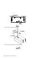
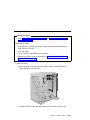
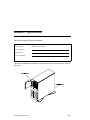
RS/6000 7025 F40 Series
IBM
User's Guide
SA38-0514-01
Second Edition (June 1997)
The following paragraph does not apply to the United Kingdom or any country where
such provisions are inconsistent with local law: THIS PUBLICATION IS PROVIDED “AS
IS” WITHOUT WARRANTY OF ANY KIND, EITHER EXPRESS OR IMPLIED, INCLUDING,
BUT NOT LIMITED TO, THE IMPLIED WARRANTIES OF MERCHANTABILITY OR FITNESS
FOR A PARTICULAR PURPOSE. Some states do not allow disclaimer of express or implied
warranties in certain transactions, therefore, this statement may not apply to you.
This publication could include technical inaccuracies or typographical errors. Changes are
periodically made to the information herein; these changes will be incorporated in new editions
of the publication. The manufacturer may make improvements and/or changes in the
product(s) and/or the program(s) described in this publication at any time, without notice.
It is possible that this publication may contain reference to, or information about, products
(machines and programs), programming, or services that are not announced in your country.
Such references or information must not be construed to mean that these products,
programming, or services will be announced in your country. Any reference to a specific
licensed program in this publication is not intended to state or imply that you can use only that
licensed program. You can use any functionally equivalent program instead.
Requests for technical information about products should be made to your authorized reseller
or marketing representative.
International Business Machines Corporation 1996, 1997. All rights reserved.
Note to U.S. Government Users -- Documentation related to restricted rights -- Use,
duplication or disclosure is subject to restrictions set forth is GSA ADP Schedule Contract with
IBM Corp.
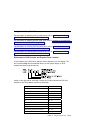
Contents
Communications Statements . . . . . . . . . . . . . . . . . . . . . . . . . . .
Federal Communications Commission (FCC) Statement . . . . . . . . . . . .
European Union (EU) Statement . . . . . . . . . . . . . . . . . . . . . . . . . .
International Electrotechnical Commission (IEC) Statement . . . . . . . . . . .
United Kingdom Telecommunications Safety Requirements . . . . . . . . . . .
Avis de conformité aux normes du ministère des Communications du Canada
Canadian Department of Communications Compliance Statement . . . . . . .
VCCI Statement . . . . . . . . . . . . . . . . . . . . . . . . . . . . . . . . . . . .
Radio Protection for Germany . . . . . . . . . . . . . . . . . . . . . . . . . . . .
Safety Notices . . . . .
Electrical Safety . . . . .
Laser Safety Information
Power Cables . . . . . .
About This Book .
ISO 9000 . . . . . .
Related Publications
Trademarks . . . .
. .
. .
. .
.
. .
. .
. .
. .
. .
. .
. .
.
. .
. .
. .
. . . . . . . . . . . . . . . . . . . . . . . . . . . . . . . . .
. . . . . . . . . . . . . . . . . . . . . . . . . . . . . . . . .
. . . . . . . . . . . . . . . . . . . . . . . . . . . . . . . . .
. . . . . . . . . . . . . . . . . . . . . . . . . . . . . . . . .
. . . . . . . . . . . . . . . . . . . . . . . . . . . . . . . . . . . .
. . . . . . . . . . . . . . . . . . . . . . . . . . . . . . . . . . . .
. . . . . . . . . . . . . . . . . . . . . . . . . . . . . . . . . . .
. . . . . . . . . . . . . . . . . . . . . . . . . . . . . . . . . . . .
Chapter 1. System Startup
Before You Begin . . . . . .
Unpacking Your System . .
Connecting the Cables . . .
Starting the System . . . . .
Finishing the Installation . .
. . . . . . . . . . . . . . . . . . . . . . . . . . . . . .
. . . . . . . . . . . . . . . . . . . . . . . . . . . . . . .
. . . . . . . . . . . . . . . . . . . . . . . . . . . . . . .
. . . . . . . . . . . . . . . . . . . . . . . . . . . . . . .
. . . . . . . . . . . . . . . . . . . . . . . . . . . . . . .
. . . . . . . . . . . . . . . . . . . . . . . . . . . . . . .
Chapter 2. Using the System Unit
Starting the System Unit . . . . . . .
Stopping the System Unit . . . . . .
Reading the Operator Panel Display
Using the Keyboards . . . . . . . . .
Using the Three–Button Mouse . . .
Copyright IBM Corp. 1997
ix
ix
. x
. x
. x
. xi
. xi
. xi
. xii
xiii
xiii
xiv
xiv
xiv
xiv
. xv
xvi
. . .
. . .
. . . . . . . . . . . . . . . . . . . . . . . . . .
. . . . . . . . . . . . . . . . . . . . . . . . . .
. . . . . . . . . . . . . . . . . . . . . . . . . .
. . . . . . . . . . . . . . . . . . . . . . . . . .
. . . . . . . . . . . . . . . . . . . . . . . . . .
. . . . . . . . . . . . . . . . . . . . . . . . . .
xvii
xvii
xix
. xx
xxiii
xxiii
xxiii
xxiii
1-1
1-2
1-3
1-5
1-7
1-9
2-1
2-1
2-1
2-2
2-3
2-5
iii
Using the 3.5–Inch Diskette Drive . . . . . . . . . .
Using the CD–ROM Drive . . . . . . . . . . . . . .
Using the Hot Swap Disk Drives . . . . . . . . . .
General Information for 5.0GB 8-mm Tape Drive .
Using the 5.0GB 8-mm Tape Drive . . . . . . . . .
General Information for 4.0GB 4-mm Tape Drive .
Using the 4.0GB 4-mm Tape Drive . . . . . . . . .
Using the 24/48GB DDS-2 4-mm Tape Autoloader
Chapter 3. System Management Services
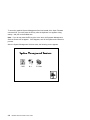
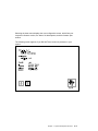
Graphical System Management Services . .
Config . . . . . . . . . . . . . . . . . . . . . . .
Boot . . . . . . . . . . . . . . . . . . . . . . . .
Utilities . . . . . . . . . . . . . . . . . . . . . .
Password . . . . . . . . . . . . . . . . . . . . .
Audio . . . . . . . . . . . . . . . . . . . . . . .
Error Log . . . . . . . . . . . . . . . . . . . . .
RIPL . . . . . . . . . . . . . . . . . . . . . . . .
SCSI ID . . . . . . . . . . . . . . . . . . . . . .
Update . . . . . . . . . . . . . . . . . . . . . .
Text-Based System Management Services .
. . . . . . . . . . . . . . . . . .
. . . . . . . . . . . . . . . . .
. . . . . . . . . . . . . . . . .
. . . . . . . . . . . . . . . . .
. . . . . . . . . . . . . . . . .
. . . . . . . . . . . . . . . . .
. . . . . . . . . . . . . . . . .
. . . . . . . . . . . . . . . . .
RS/6000 7025 F40 Series User's Guide
3-1
. 3-1
. 3-4
. 3-7
. 3-9
3-11
3-15
3-16
3-17
3-21
3-22
3-24
. . . . . . . . . . . . . . . . . . . . .
. . . . . . . . . . . . . . . . . . . .
. . . . . . . . . . . . . . . . . . . .
. . . . . . . . . . . . . . . . . . . .
. . . . . . . . . . . . . . . . . . . .
. . . . . . . . . . . . . . . . . . . .
. . . . . . . . . . . . . . . . . . . .
. . . . . . . . . . . . . . . . . . . .
. . . . . . . . . . . . . . . . . . . .
. . . . . . . . . . . . . . . . . . . .
. . . . . . . . . . . . . . . . . . . .
. . . . . . . . . . . . . . . . . . . .
Chapter 4. Installing Options . . . . . . . . . . . . . . . . . . . . . . .
Safety Considerations . . . . . . . . . . . . . . . . . . . . . . . . . . . .
Handling Static-Sensitive Devices . . . . . . . . . . . . . . . . . . . . . .
Expansion Bays . . . . . . . . . . . . . . . . . . . . . . . . . . . . . . . .
Input/Output Connectors . . . . . . . . . . . . . . . . . . . . . . . . . . .
Removing the Front Covers Only . . . . . . . . . . . . . . . . . . . . . .
Removing Both the Front and Side Covers . . . . . . . . . . . . . . . .
Removing the System Board Cover . . . . . . . . . . . . . . . . . . . .
Option List . . . . . . . . . . . . . . . . . . . . . . . . . . . . . . . . . . .
Installing Memory-Modules . . . . . . . . . . . . . . . . . . . . . . . . . .
Removing Memory-Modules . . . . . . . . . . . . . . . . . . . . . . . . .
Installing Adapters . . . . . . . . . . . . . . . . . . . . . . . . . . . . . . .
Removing Adapters . . . . . . . . . . . . . . . . . . . . . . . . . . . . . .
Upgrading or Adding CPU Card . . . . . . . . . . . . . . . . . . . . . . .
Installing Internal Drives . . . . . . . . . . . . . . . . . . . . . . . . . . .
Installing a Disk Drive, Tape Drive, or CD-ROM in Bay A or Bay B . .
Installing a Hot-Swap SCSI Disk Drive in Bank C, D, or E. . . . . . . .
Installing a Hot-Swap SSA Disk Drive in Bank C, D, or E . . . . . . . .
Installing a SCSI Backplane in Bank C . . . . . . . . . . . . . . . . . . .
Installing a SSA Backplane in Bank C or E . . . . . . . . . . . . . . . .
Removing Internal Drives . . . . . . . . . . . . . . . . . . . . . . . . . .
Removing a Disk Drive, Tape Drive, or CD-ROM from Bay A or Bay B
iv
2-8
2-10
2-13
2-18
2-23
2-28
2-34
2-39
4-1
4-1
. 4-3
. 4-4
. 4-5
. 4-6
4-10
4-16
4-17
4-18
4-22
4-25
4-30
4-33
4-36
4-41
4-48
4-52
4-56
4-63
4-78
4-79
. . . . . .
. . . . . .
. . . . .
. . . . .
. . . . .
. . . . .
. . . . .
. . . . .
. . . . .
. . . . .
. . . . .
. . . . .
. . . . .
. . . . .
. . . . .
. . . . .
. . . . .
. . . . .
. . . . .
. . . . .
. . . . .
. . . . .
Removing a Hot-Swap SCSI Disk Drive from Bank C, D, or E
Removing a Hot-Swap SSA Disk Drive from Bank C, D, or E
Installing a Service Processor . . . . . . . . . . . . . . . . . . .
Installing a U-Bolt . . . . . . . . . . . . . . . . . . . . . . . . . .
Replacing the Front Covers . . . . . . . . . . . . . . . . . . . .
Replacing Both the Front and Side Covers . . . . . . . . . . .
Replacing the System Board Cover . . . . . . . . . . . . . . . .
. . . . . . . . . .
. . . . . . . . . .
. . . . . . . . . .
. . . . . . . . . .
. . . . . . . . . .
. . . . . . . . . .
. . . . . . . . .
Chapter 5. Using the Standalone and Online Diagnostics . . . .
Sources for the Diagnostic Programs . . . . . . . . . . . . . . . . . . .
Standalone and Online Diagnostics Operating Considerations . . . .
Online Diagnostics Mode of Operation . . . . . . . . . . . . . . . . . .
Running the Online Diagnostics in Service Mode (Service Mode IPL)
Standalone Diagnostic Operation . . . . . . . . . . . . . . . . . . . . .
Running the Standalone Diagnostics . . . . . . . . . . . . . . . . . . .
General Information About Multiple Systems . . . . . . . . . . . . . .
High-Availability SCSI . . . . . . . . . . . . . . . . . . . . . . . . . . . .
Diagnostic Summary . . . . . . . . . . . . . . . . . . . . . . . . . . . .
4.2 Diagnostic Changes . . . . . . . . . . . . . . . . . . . . . . . . . .
Location Codes . . . . . . . . . . . . . . . . . . . . . . . . . . . . . . .
4-80
4-84
4-88
4-91
4-93
4-96
4-101
5-1
5-1
. 5-1
. 5-9
5-10
5-13
5-13
5-14
5-15
5-15
5-16
5-19
. . . . . . .
. . . . . . .
. . . . . .
. . . . . .
. . . . . .
. . . . . .
. . . . . .
. . . . . .
. . . . . .
. . . . . .
. . . . . .
. . . . . .
Chapter 6. Introduction to Tasks and Service Aids . . . . . . . . . . . . . .
AIX Shell Prompt Service Aid . . . . . . . . . . . . . . . . . . . . . . . . . . . . .
Backup/Restore Media Service Aid . . . . . . . . . . . . . . . . . . . . . . . . . .
Configure Ring Indicate Power On Service Aid . . . . . . . . . . . . . . . . . . .
Configure Service Processor Service Aid . . . . . . . . . . . . . . . . . . . . . .
Create Customized Diagnostic Configuration Diskette . . . . . . . . . . . . . . .
Diagnostic Package Utility Service Aid . . . . . . . . . . . . . . . . . . . . . . . .
Dials and LPFK Configuration Service Aid . . . . . . . . . . . . . . . . . . . . . .
Disk Based Diagnostic Update Service Aid and Update Disk Based Diagnostic
Task
. . . . . . . . . . . . . . . . . . . . . . . . . . . . . . . . . . . . . . . . . .
Disk Media Service Aids . . . . . . . . . . . . . . . . . . . . . . . . . . . . . . . .
Disk Maintenance Service Aid . . . . . . . . . . . . . . . . . . . . . . . . . . . . .
Diskette Media Service Aid . . . . . . . . . . . . . . . . . . . . . . . . . . . . . .
Display/Alter Bootlist Service Aid . . . . . . . . . . . . . . . . . . . . . . . . . . .
Display or Change Configuration or Vital Product Data (VPD) Service Aid . . .
Display and Change Diagnostic Test List Service Aid . . . . . . . . . . . . . . .
Display Machine Check Error Log Service Aid . . . . . . . . . . . . . . . . . . .
Display Previous Diagnostic Results Service Aid . . . . . . . . . . . . . . . . . .
Display Resource Attributes . . . . . . . . . . . . . . . . . . . . . . . . . . . . . .
Display Test Patterns Service Aid . . . . . . . . . . . . . . . . . . . . . . . . . . .
Generic Microcode Download Service Aid . . . . . . . . . . . . . . . . . . . . . .
Hardware Error Report Service Aid and Display Hardware Error Log Task . . .
ISA Adapter Configuration Service Aid . . . . . . . . . . . . . . . . . . . . . . . .
.
.
.
.
.
.
.
.
6-1
6-3
6-3
6-3
6-3
6-5
6-5
6-6
6-6
6-7
. 6-9
6-11
6-11
6-11
6-14
6-14
6-15
6-15
6-16
6-16
6-16
6-16
.
.
Preface
v
Local Area Network Service Aid and Local Area Network Analyzer Task
Microcode Download Service Aid . . . . . . . . . . . . . . . . . . . . . . .
PCI RAID Physical Disk Identify . . . . . . . . . . . . . . . . . . . . . . . .
Periodic Diagnostics Service Aid . . . . . . . . . . . . . . . . . . . . . . .
Process Supplemental Media Task . . . . . . . . . . . . . . . . . . . . . .
Run Diagnostics Task . . . . . . . . . . . . . . . . . . . . . . . . . . . . .
Run Error Log Analysis Task . . . . . . . . . . . . . . . . . . . . . . . . .
SCSI Bus Service Aid and SCSI Bus Analyzer Task . . . . . . . . . . . .
SCSI Device Identification and Removal . . . . . . . . . . . . . . . . . . .
SCSI Tape Utilities Service Aid . . . . . . . . . . . . . . . . . . . . . . . .
Service Hints Service Aid . . . . . . . . . . . . . . . . . . . . . . . . . . .
SSA Service Aids . . . . . . . . . . . . . . . . . . . . . . . . . . . . . . . .
7135 RAIDiant Array Service Aid . . . . . . . . . . . . . . . . . . . . . . .
7318 Serial Communications Network Server Service Aid . . . . . . . . .
SSA Location Code Format . . . . . . . . . . . . . . . . . . . . . . . . . .
SSA Loops and Links . . . . . . . . . . . . . . . . . . . . . . . . . . . . . .
SSA Service Aids . . . . . . . . . . . . . . . . . . . . . . . . . . . . . . . .
Service Aid Error Codes . . . . . . . . . . . . . . . . . . . . . . . . . . . .
Using the Service Aids for SSA-Link Problem Determination . . . . . . .
Finding the Physical Location of a Device . . . . . . . . . . . . . . . . . .
Microcode Maintenance . . . . . . . . . . . . . . . . . . . . . . . . . . . .
Vital Product Data (VPD) . . . . . . . . . . . . . . . . . . . . . . . . . . . .
Chapter 7. Using the System Verification Procedure
Step 1. Considerations before Running This Procedure .
Step 2. Loading the Diagnostics . . . . . . . . . . . . . . .
Step 3. Running System Verification . . . . . . . . . . . .
Step 4. Additional System Verification . . . . . . . . . . .
Step 5. Stopping the Diagnostics . . . . . . . . . . . . . .
. . . .
. . . .
. . . .
. . . .
. . . .
. . . .
. . . .
. . . .
. . . .
. . . .
. . . .
. . . .
. . . .
. . . .
. . . .
. . . .
. . . .
. . . .
. . . .
. . . .
. . . . . . . . . . . . . .
. . . . . . . . . . . . . .
. . . . . . . . . . . . . .
. . . . . . . . . . . . . .
. . . . . . . . . . . . . .
. . . . . . . .
. . . . . . .
. . . . . . .
. . . . . . . . . . . . . . . . . . . . . . . . . . . .
. . . . . . . . . . . . . . . . . . . . . . . . . . .
. . . . . . . . . . . . . . . . . . . . . . . . . . . .
Appendix B. Replacing the Battery
. . . . . . . . . . . . . . . . . . . . . . . . .
Appendix C. POWER GXT1000 Internal Graphics Accelerator
Overview . . . . . . . . . . . . . . . . . . . . . . . . . . . . . . . . .
POWER GXT1000 Locations . . . . . . . . . . . . . . . . . . . . .
POWER GXT1000 Removal and Replacement . . . . . . . . . . .
vi
. . . .
. . . . . . . . . . . . . .
Chapter 8. Hardware Problem Determination . . . . . . . . . . .
Problem Determination Using the Standalone or Online Diagnostics
Problem Determination When Unable to Load Diagnostics . . . . .
Appendix A. System Records
Record the Identification Numbers
Device Records . . . . . . . . . .
. . . .
RS/6000 7025 F40 Series User's Guide
. . . . . . . . .
. . . . . . . . .
. . . . . . . . .
. . . . . . . . .
6-18
6-18
6-18
6-19
6-19
6-20
6-20
6-20
6-22
6-22
6-23
6-23
6-23
6-24
6-24
6-25
6-30
6-49
6-50
6-56
6-58
6-59
7-1
7-1
7-2
7-3
7-3
7-4
8-1
8-1
8-10
A-1
A-1
A-2
B-1
C-1
C-1
C-3
C-5
POWER GXT1000 System Considerations . . . . . . . . . . . . . . . . . . .
Virtual Terminal Restrictions (Hot Key) . . . . . . . . . . . . . . . . . . . . . .
Defining Overlay and Color Plane Visuals . . . . . . . . . . . . . . . . . . . .
Starting the X server for the 3D API's . . . . . . . . . . . . . . . . . . . . . .
Defining Texture Map Configurations . . . . . . . . . . . . . . . . . . . . . . .
Gamma Correction . . . . . . . . . . . . . . . . . . . . . . . . . . . . . . . . .
Determining the POWER GXT1000 Hardware Configuration . . . . . . . . .
POWER GXT1000 Performance When Rendering to a Double Buffer Visual
Understanding POWER GXT1000 Visuals . . . . . . . . . . . . . . . . . . . .
Understanding Visuals . . . . . . . . . . . . . . . . . . . . . . . . . . . . . . .
X Visual Classes . . . . . . . . . . . . . . . . . . . . . . . . . . . . . . . . . .
Understanding Video . . . . . . . . . . . . . . . . . . . . . . . . . . . . . . . .
VOO Overview . . . . . . . . . . . . . . . . . . . . . . . . . . . . . . . . . . . .
Stereo Overview . . . . . . . . . . . . . . . . . . . . . . . . . . . . . . . . . . .
Video Library and Header File Locations . . . . . . . . . . . . . . . . . . . . .
Interface Description . . . . . . . . . . . . . . . . . . . . . . . . . . . . . . . .
Video Library Error Handling . . . . . . . . . . . . . . . . . . . . . . . . . . . .
Index
. .
. .
. .
. .
. .
. .
. .
. .
. .
. .
. .
. .
. .
. .
. .
. .
. .
C-18
C-18
C-18
C-19
C-21
C-26
C-27
C-29
C-30
C-30
C-34
C-36
C-36
C-37
C-38
C-38
C-38
. . . . . . . . . . . . . . . . . . . . . . . . . . . . . . . . . . . . . . . . . . . .
X-1
Preface
vii
viii
RS/6000 7025 F40 Series User's Guide
Communications Statements
The following statement applies to this product. The statement for other products
intended for use with this product appears in their accompanying manuals.
If the Graphics Subsystem or the Video Output Option is NOT installed, this system
complies with the limits for a Class B digital device, pursuant to Part 15 of the FCC
Rules.
Federal Communications Commission (FCC) Statement
Note: The IBM 7025 Model F40 has been tested and found to comply with the
limits for a Class B digital device, pursuant to Part 15 of the FCC Rules. These
limits are designed to provide reasonable protection against harmful interference in a
residential installation. This equipment generates, uses, and can radiate radio
frequency energy and, if not installed and used in accordance with the instructions,
may cause harmful interference to radio communications. However, there is no
guarantee that interference will not occur in a particular installation. If this equipment
does cause harmful interference to radio or television reception, which can be
determined by turning the equipment off and on, the user is encouraged to try to
correct the interference by one or more of the following measures:
Reorient or relocate the receiving antenna.
Increase the separation between the equipment and receiver.
Connect the equipment into an outlet on a circuit different from that to which the
receiver is connected.
Consult an authorized dealer or service representative for help.
Properly shielded and grounded cables and connectors must be used in order to
meet FCC emission limits. Proper cables and connectors are available from
authorized dealers. Neither the provider nor the manufacturer are responsible for
any radio or television interference caused by using other than recommended cables
and connectors or by unauthorized changes or modifications to this equipment.
Unauthorized changes or modifications could void the user's authority to operate the
equipment.
This device complies with Part 15 of the FCC Rules. Operation is subject to the
following two conditions: (1) this device may not cause harmful interference, and (2)
this device must accept any interference received, including interference that may
cause undesired operation.
Responsible Party:
Copyright IBM Corp. 1997
ix
International Business Machines Corporation
Old Orchard Road
Armonk, New York 10504
Telephone: (919) 543-2193
European Union (EU) Statement
This product is in conformity with the protection requirements of EU Council Directive
89/336/EEC on the approximation of the laws of the Member States relating to
electromagnetic compatibility. The manufacturer cannot accept responsibility for any
failure to satisfy the protection requirements resulting from a non-recommended
modification of the product, including the fitting of option cards supplied by third
parties. Consult with your dealer or sales representative for details on your specific
hardware.
This product has been tested and found to comply with the limits for Class B
Information Technology Equipment according to CISPR 22 / European Standard EN
55022. The limits for Class B equipment were derived for typical residential
environments to provide reasonable protection against interference with licensed
communication devices.
International Electrotechnical Commission (IEC) Statement
This product has been designed and built to comply with IEC Standard 950.
United Kingdom Telecommunications Safety Requirements
This equipment is manufactured to the International Safety Standard EN60950 and
as such is approved in the UK under the General Approval Number
NS/G/1234/J/100003 for indirect connection to the public telecommunication network.
The network adapter interfaces housed within this equipment are approved
separately, each one having its own independent approval number. These interface
adapters, supplied by the manufacturer, do not use or contain excessive voltages.
An excessive voltage is one which exceeds 70.7 V peak ac or 120 V dc. They
interface with this equipment using Safe Extra Low Voltages only. In order to
maintain the separate (independent) approval of the manufacturer's adapters, it is
essential that other optional cards, not supplied by the manufacturer, do not use
main voltages or any other excessive voltages. Seek advice from a competent
engineer before installing other adapters not supplied by the manufacturer.
x
RS/6000 7025 F40 Series User's Guide
Avis de conformité aux normes du ministère des Communications du
Canada
Cet appareil numérique de la classe B respecte toutes les exigences du Réglement
sur le matériel brouilleur du Canada.
Canadian Department of Communications Compliance Statement
This Class B digital apparatus meets the requirements of the Canadian
Interference-Causing Equipment Regulations.
VCCI Statement
The following is a summary of the VCCI Japanese statement in the box above.
This equipment is in the Class 2 category (information equipment to be used in a
residential area or an adjacent area thereto) and conforms to the standards set by
the Voluntary Control Council For Interference by Data Processing Equipment and
Electronic Office Machines aimed at preventing radio interference in such residential
area.
When used near a radio or TV receiver, it may become the cause of radio
interference.
Read the instructions for correct handling.
Preface
xi
Radio Protection for Germany
Dieses Gerät ist berechtigt in Übereinstimmung mit dem deutschen EMVG vom
9.Nov.92 das EG–Konformitätszeichen zu führen.
Der Aussteller der Konformitätserklärung ist die IBM Germany.
Dieses Gerät erfüllt die Bedingungen der EN 55022 Klasse B.
xii
RS/6000 7025 F40 Series User's Guide
If the Graphics Subsystem (Feature Code 7252 or 7253) or the Video Output Option
(Feature Code 7254) IS installed, this system complies with the limits for a Class A
digital device, pursuant to Part 15 of the FCC Rules.
Federal Communications Commission (FCC) Statement
Note: This equipment has been tested and found to comply with the limits for a
Class A digital device, pursuant to Part 15 of the FCC Rules. These limits are
designed to provide reasonable protection against harmful interference when the
equipment is operated in a commercial environment. This equipment generates,
uses, and can radiate radio frequency energy and, if not installed and used in
accordance with the instruction manual, may cause harmful interference to radio
communications. Operation of this equipment in a residential area is likely to cause
harmful interference in which case the user will be required to correct the
interference at his own expense.
Properly shielded and grounded cables and connectors must be used in order to
meet FCC emission limits. Neither the provider nor the manufacturer are responsible
for any radio or television interference caused by using other than recommended
cables and connectors or by unauthorized changes or modifications to this
equipment. Unauthorized changes or modifications could void the user's authority to
operate the equipment.
This device complies with Part 15 of the FCC Rules. Operation is subject to the
following two conditions: (1) this device may not cause harmful interference,and (2)
this device must accept any interference received, including interference that may
cause undesired operation.
European Union (EU) Statement
This product is in conformity with the protection requirements of EU Council Directive
89/336/EEC on the approximation of the laws of the Member States relating to
electromagnetic compatibility. The manufacturer cannot accept responsibility for any
failure to satisfy the protection requirements resulting from a non-recommended
modification of the product, including the fitting of option cards supplied by third
parties. Consult with your dealer or sales representative for details on your specific
hardware.
This product has been tested and found to comply with the limits for Class A
Information Technology Equipment according to CISPR 22 / European Standard EN
55022. The limits for Class A equipment were derived for commercial and industrial
environments to provide reasonable protection against interference with licensed
communication equipment.
Preface
xiii
Attention: This is a Class A product. In a domestic environment this product may
cause radio interference in which case the user may be required to take adequate
measures.
International Electrotechnical Commission (IEC) Statement
This product has been designed and built to comply with IEC Standard 950.
United Kingdom Telecommunications Safety Requirements
This equipment is manufactured to the International Safety Standard EN60950 and
as such is approved in the UK under the General Approval Number
NS/G/1234/J/100003 for indirect connection to the public telecommunication network.
The network adapter interfaces housed within this equipment are approved
separately, each one having its own independent approval number. These interface
adapters, supplied by the manufacturer, do not use or contain excessive voltages.
An excessive voltage is one which exceeds 70.7 V peak ac or 120 V dc. They
interface with this equipment using Safe Extra Low Voltages only. In order to
maintain the separate (independent) approval of the manufacturer's adapters, it is
essential that other optional cards, not supplied by the manufacturer, do not use
main voltages or any other excessive voltages. Seek advice from a competent
engineer before installing other adapters not supplied by the manufacturer.
Avis de conformité aux normes du ministère des Communications du
Canada
Cet appareil numérique de la classe A respecte toutes les exigences du Réglement
sur le matériel brouilleur du Canada.
Canadian Department of Communications Compliance Statement
This Class A digital apparatus meets the requirements of the Canadian
Interference–Causing Equipment Regulations.
xiv
RS/6000 7025 F40 Series User's Guide
VCCI Statement
The following is a summary of the VCCI Japanese statement in the box above.
This equipment is in the Class 1 category (information equipment to be used in
commercial and/or industrial areas) and conforms to the standards set by the
Voluntary Control Council For Interference by Data Processing Equipment and
Electronic Office Machines aimed at preventing radio interference in commercial
and/or industrial areas.
Consequently, when used in a residential area or in an adjacent area thereto, radio
interference may be caused to radios and TV receivers, etc.
Read the instructions for correct handling. VCCI-1.
Preface
xv
Radio Protection for Germany
Dieses Gerät ist berechtigt in Übereinstimmung mit dem deutschen EMVG vom
9.Nov.92 das EG–Konformitätszeichen zu führen.
Der Aussteller der Konformitätserklärung ist die IBM Germany.
Dieses Gerät erfüllt die Bedingungen der EN 55022 Klasse A. Für diese von
Geräten gilt folgende Bestimmung nach dem EMVG:
Geräte dürfen an Orten, für die sie nicht ausreichend entstört sind, nur mit
besonderer Genehmigung des Bundesministers für Post und Telekommunikation
oder des Bundesamtes für Post und Telekommunikation betrieben werden. Die
Genehmigung wird erteilt, wenn keine elektromagnetischen Störungen zu erwarten
sind.
(Auszug aus dem EMVG vom 9.Nov.92, Para.3, Abs.4)
Hinweis
Dieses Genehmigungsverfahren ist von der Deutschen Bundespost noch nicht
veröffentlicht worden.
xvi
RS/6000 7025 F40 Series User's Guide
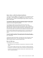
Safety Notices
A danger notice indicates the presence of a hazard that has the potential of causing
death or serious personal injury.
A caution notice indicates the presence of a hazard that has the potential of causing
moderate or minor personal injury.
Electrical Safety
Observe the following safety instructions any time you are connecting or
disconnecting devices attached to the workstation.
DANGER
An electrical outlet that is not correctly wired could place hazardous
voltage on metal parts of the system or the devices that attach to the
system. It is the responsibility of the customer to ensure that the outlet
is correctly wired and grounded to prevent an electrical shock.
Before installing or removing signal cables, ensure that the power
cables for the system unit and all attached devices are unplugged.
When adding or removing any additional devices to or from the system,
ensure that the power cables for those devices are unplugged before
the signal cables are connected. If possible, disconnect all power
cables from the existing system before you add a device.
Use one hand, when possible, to connect or disconnect signal cables
to prevent a possible shock from touching two surfaces with different
electrical potentials.
During an electrical storm, do not connect cables for display stations,
printers, telephones, or station protectors for communication lines.
CAUTION:
This product is equipped with a three–wire power cable and plug for the user's
safety. Use this power cable with a properly grounded electrical outlet to avoid
electrical shock.
Copyright IBM Corp. 1997
xvii
DANGER
To prevent electrical shock hazard, disconnect the power cable from
the electrical outlet before relocating the system.
xviii
RS/6000 7025 F40 Series User's Guide
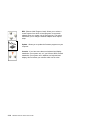
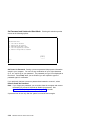
Laser Safety Information
The optical drive in this system unit is a laser product. The optical drive has a label
that identifies its classification. The label, located on the drive, is shown below.
CLASS 1 LASER PRODUCT
LASER KLASSE 1
LUOKAN 1 LASERLAITE
APPAREIL A LASER DE CLASSE 1
IEC 825:1984 CENELEC EN 60 825:1991
The optical drive in this system unit is certified in the U.S. to conform to the
requirements of the Department of Health and Human Services 21 Code of Federal
Regulations (DHHS 21 CFR) Subchapter J for Class 1 laser products. Elsewhere,
the drive is certified to conform to the requirements of the International
Electrotechnical Commission (IEC) 825 (1st edition 1984) and CENELEC EN 60
825:1991 for Class 1 laser products.
CAUTION:
A class 3 laser is contained in the device. Do not attempt to operate the drive
while it is disassembled. Do not attempt to open the covers of the drive as it
is not serviceable and is to be replaced as a unit.
Class 1 laser products are not considered to be hazardous. The optical drive
contains internally a Class 3B gallium-arsenide laser that is nominally 30 milliwatts at
830 nanometers. The design incorporates a combination of enclosures, electronics,
and redundant interlocks such that there is no exposure to laser radiation above a
Class 1 level during normal operation, user maintenance, or servicing conditions.
Preface
xix
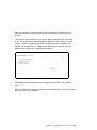
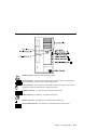
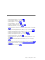
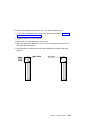
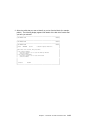
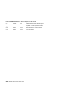
Power Cables
1
2
5
8
6
9
4
3
7
10
11
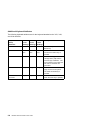
Index
Part Number
Country
1
1838574
Bahamas, Barbados, Bolivia, Brazil, Canada, Costa Rica,
Dominican Republic, El Salvador, Ecuador, Guatemala, Guyana,
Haiti, Honduras, Jamaica, Japan, Netherlands Antilles, Panama,
Peru, Philippines, Taiwan, Thailand, Trinidad, Tobago, U.S.A.
(except Chicago), Venezuela
2
6952300
Bahamas, Barbados, Bermuda, Bolivia, Brazil, Canada, Cayman
Islands, Colombia, Costa Rica, Dominican Republic, Ecuador, El
Salvador, Guatemala, Guyana, Haiti, Honduras, Jamaica, Japan,
Korea (South), Mexico, Netherlands Antilles, Nicaragua, Panama,
Peru, Philippines, Puerto Rico, Saudi Arabia, Suriname, Trinidad,
Taiwan, U.S.A. (except Chicago), Venezuela
2
62X1045
Chicago, U.S.A.
3
6952311
Argentina, Australia, New Zealand
4
13F9979
Abu Dhabi, Austria, Belgium, Bulgaria, Botswana, Egypt, Finland,
France, Germany, Greece, Iceland, Indonesia, Korea (South),
Lebanon, Luxembourg, Macau, Netherlands, Norway, Portugal,
Saudi Arabia, Spain, Sudan, Sweden, Turkey, Yugoslavia
5
13F9997
Denmark
6
14F0015
Bangladesh, Burma, Pakistan, South Africa, Sri Lanka
7
14F0033
Bahrain, Bermuda, Brunei, Channel Islands, Cyprus, Ghana,
Hong Kong, India, Iraq, Ireland, Jordan, Kenya, Kuwait, Malawi,
Malaysia, Nigeria, Oman, People's Republic of China, Qatar,
Sierra Leone, Singapore, Tanzania, Uganda, United Arab
Emirates (Dubai), United Kingdom, Zambia
xx
RS/6000 7025 F40 Series User's Guide
Index
Part Number
Country
8
14F0051
Liechtenstein, Switzerland
9
14F0069
Chile, Ethiopia, Italy
10
14F0087
Israel
11
6952291
Paraguay, Colombia, Uruguay
Preface
xxi
xxii
RS/6000 7025 F40 Series User's Guide
About This Book
This book provides information on how to install and remove options, use the
system, use diagnostics, use service aids, and verify system operation. This book
also provides information to help you solve some of the simpler problems that might
occur.
ISO 9000
ISO 9000 registered quality systems were used in the development and
manufacturing of this product.
Related Publications
The following publications are available:
The RS/6000 7025 F40 Series Service Guide contains reference information,
maintenance analysis procedures (MAPs), error codes, removal and replacement
procedures, and a parts catalog.
The RS/6000 Diagnostic Information for Multiple Bus Systems contains
diagnostic information, service request numbers (SRNs), and failing function
codes (FFCs).
The RS/6000 Adapter, Device, and Cable Information for Multiple Bus Systems
contains information about adapters, devices, and cables for your system. This
manual is intended to supplement the service information found in the RS/6000
Diagnostic Information for Multiple Bus Systems.
The Site and Hardware Planning Information contains information to help you
plan your installation.
Trademarks
PowerPC is a trademark of the International Business Machines Corporation.
graPHIGS is a trademark of the International Business Machines Corporation.
OpenGL is a trademark of Silicon Graphics, Inc.
PEX is a trademark of Massachusetts Institute of Technology.
AIX is a registered trademark of the International Business Machines
Corporation.
Velcro is a trademark of Velcro Industries.
Copyright IBM Corp. 1997
xxiii
xxiv
RS/6000 7025 F40 Series User's Guide
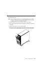
Chapter 1. System Startup
Thank you for selecting an RS/6000 7025 F40 Series system!
The RS/6000 7025 F40 Series system combines PowerPC 604 microprocessor
performance and system expandability, ensuring that your system adapts to handle
ever-changing operating requirements. The system is specifically designed to
support the demands of network environments.
The RS/6000 7025 F40 Series system incorporates the new, advanced peripheral
component interconnect (PCI) bus, which is faster than the industry standard
architecture (ISA) bus. But the system also offers ISA as a secondary bus
architecture, to accommodate businesses that already have invested in ISA and
ISA-based devices.
This book helps you set up and use the system, install and remove options,
configure the system, and use the system programs that are provided. This book
also provides information to help you solve some of the simpler problems that might
occur, and how to obtain assistance and service. Appendix A, “System Records” on
page A-1 provides a section for you to record all the important information about
your system.
Copyright IBM Corp. 1997
1-1
Before You Begin
Make sure you have an adequate number of properly grounded electrical outlets
for your system, display, and any other options you intend to install.
Place your system in a location that is dry. Rain or spilled liquids might damage
your system.
Always operate your system in the upright position and do not place any heavy
objects on top of your system.
Leave about 51 mm (2 in.) of space on all sides of the system to allow the
system's cooling system to work properly.
Collect the following tools, and keep them handy:
– Small flat-blade screwdriver
– Medium flat-blade screwdriver
– Trays to hold screws
1-2
RS/6000 7025 F40 Series User's Guide
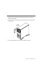
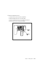
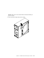
Unpacking Your System
CAUTION:
To avoid possible injury while moving or lifting the system, ask another person
to help you.
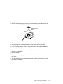
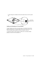
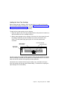
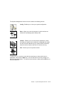
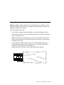
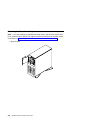
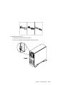
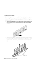
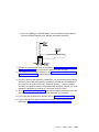
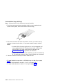
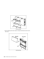
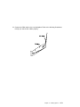
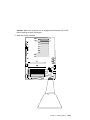
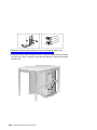
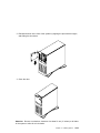
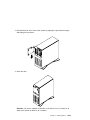
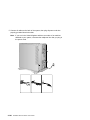
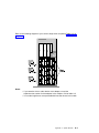
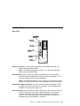
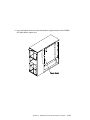
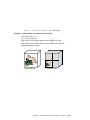
Moving the System
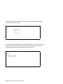
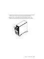
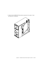
When the system is in the normal upright position, move it by lifting up on the handle
on the front and moving it forward or backward as shown. (There is a roller built into
the rear of the system's base.)
Chapter 1. System Startup
1-3
Preinstallation Checklist
After you unpack your system, display or ASCII terminal, and optional devices, make
sure you have the following items:
System and power cord
ASCII terminal (or keyboard, keyboard cable, display, display cable, and
display power cord)
Mouse (if using display and keyboard)
Other publications and media (for example, CD-ROM) that came with the
system
Options you want to install
Contact your authorized reseller or marketing representative if any items are missing
or damaged.
1-4
RS/6000 7025 F40 Series User's Guide
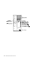
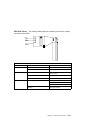
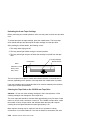
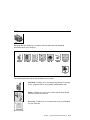
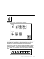
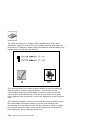
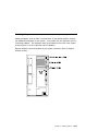
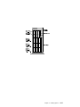
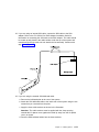
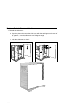
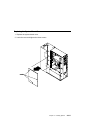
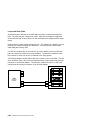
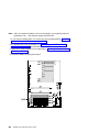
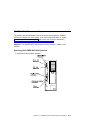
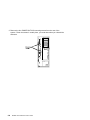
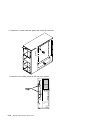
Connecting the Cables
1. If you are using a keyboard, attach the keyboard cable to the keyboard
connector (
).
2. If you are using a display, attach the display to the display connector on the back
of the display adapter in one of the expansion slots. See the About Your
Machine document for information on preinstalled adapters.
3. If you are using an ASCII terminal, connect the terminal to serial port 1 (
).
4. If you are installing a mouse or other pointing device, connect that cable to the
mouse connector ( ).
5. If you are installing a tablet, connect that cable to the tablet connector (
).
6. Connect the display or ASCII terminal power cord to the display or ASCII
terminal.
7. Attach adapter cables to any adapters installed in the expansion slots. See the
About Your Machine document for information on preinstalled adapters. For
more instructions on adapter cabling, see the documentation that came with your
adapter, or to the RS/6000 Adapter, Device, and Cable Information for Multiple
Bus Systems.
8. Make sure the system's power is turned off.
9. Connect the system connector power cord to the power connector. Secure all
these connections, then plug the display power cord and the system power cord
into properly grounded electrical outlets.
Chapter 1. System Startup
1-5
1-6
RS/6000 7025 F40 Series User's Guide
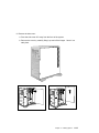
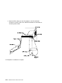
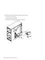
Starting the System
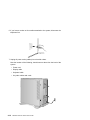
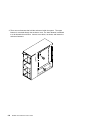
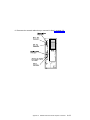
1. Open the door. If the diskette drive contains packing material or a diskette,
remove it from the drive.
2. Remove the extra key and ID tag that is taped inside the door and store them in
a secure place.
3. Turn on all external devices, such as printers, plotters, or modems.
Chapter 1. System Startup
1-7
4. Press the Power On switch.
5. Check your display or ASCII terminal for configuration information displayed as
the power-on self-test (POST) begins. The system beeps once to indicate it is
working properly.
If no operating system is installed, you are prompted to select the operating
system installation device.
1-8
RS/6000 7025 F40 Series User's Guide
Finishing the Installation
Important
Be sure to maintain at least 51 mm (2 in.) of space on all sides of the system
to allow the system's cooling system to work properly. Blocking the air vents
can cause overheating, which might result in a malfunction or permanent
damage.
Your system hardware is set up, and you are ready to learn about your system and
make backup copies of important software. The order in which you do these tasks is
up to you. Use the following checklist as a guide.
Record your identification numbers
Your system has important identification information that you might need if you
have it serviced. Appendix A, “System Records” on page A-1 shows where to
find these numbers, and provides space to record and retain this information.
Install options
If you decided earlier to delay installing your options, you might want to
complete these installations now. See Chapter 4, “Installing Options” on
page 4-1 for handling and installation instructions.
Install the Operating System
If AIX is preinstalled in your system unit, or if you plan to install AIX yourself,
refer to the Quick Installation and Startup Guide for instructions.
Some options that you might install come with a diskette that contains device
drivers, configuration files, or test programs. To install these files (after your
operating system is installed), follow the instructions that come with the
diskettes.
Install application programs
To install application programs, follow the instructions supplied with each
application program.
Chapter 1. System Startup
1-9
1-10
RS/6000 7025 F40 Series User's Guide
Chapter 2. Using the System Unit
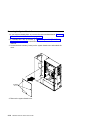
Starting the System Unit
1. Set the power switches of the attached devices to On.
2. Press the Power On switch.
When you press the Power On switch, the Power On LED comes on and the
system starts a POST (power-on self test).
During POST, progress codes display in the operator panel display.
3. If power does not come on when you press the Power On switch, ensure that the
power cord, located at the back of the system unit, is plugged into a grounded
electrical outlet. If this does not solve the problem, go to Chapter 8, “Hardware
Problem Determination” on page 8-1.
Stopping the System Unit
Attention: When using the shutdown procedure for your system, enter the correct
command before you stop the system unit. Failure to do so may result in the loss of
data. If you need information on the shutdown procedure for your operating system,
see your operating system information.
1. Before stopping the system unit, you must first perform a shutdown procedure of
the operating system to prevent the loss of data.
2. After you shut down the operating system, set the power switches of the
attached devices to Off.
3. Stop the system unit by pressing the Power On switch.
Copyright IBM Corp. 1997
2-1
Reading the Operator Panel Display
The operator panel display is used to:
Track the progress of the system unit self tests and configuration program.
Display codes when the operating system comes to an abnormal end.
Display system messages.
During power-on self-test (POST), 3 characters display indicating the progress of the
testing. If an error is detected that requires attention, the system unit halts and an 8
digit number displays in the operator panel display to identify the error.
2-2
RS/6000 7025 F40 Series User's Guide
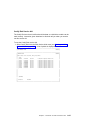
Using the Keyboards
There are several keyboards available for the system unit. The keyboards have
various keys that enter data and control the cursor location. The keyboards can be
engraved for the languages of different countries.
The functions of each keyboard depend on the software used. The character sets for
the keyboards are contained and explained in the information for your operating
system.
Function Keys
Esc
F1
F2
F3
F4
F5
F6
F7
F8
F9
F10
F11
F12
Print
Screen
Scroll
Lock
SysRq
@
!
1
Tab
$
4
#
3
2
Q
W
%
5
E
*
&
7
6
R
T
(
9
8
Y
U
_
-
)
0
I
O
+
=
Backspace
P
Insert
Delete
Pause
Num
Lock
Caps
Lock
Scroll
Lock
Break
Home
Page
Up
End
Page
Down
Num
Lock
/
*
7
8
9
Home
-
Pg Up
+
Caps
Lock
Shift
A
S
Z
D
X
F
C
G
V
H
B
J
N
K
M
L
<
,
:
;
"
,
?
/
>
.
Enter
Shift
4
5
1
2
End
6
3
Pg Dn
Enter
Ctrl
Alt
Alt
Typewriter Keys
Ctrl
Control
Keys
0
.
Ins
Del
Numeric
Keypad
The keyboard is divided into four sections:
Function keys are multipurpose keys and their function is controlled by the
operating system.
Typewriter keys are similar to a standard typewriter. Their function is controlled
by the software.
Control keys move the cursor on the screen and do programmed control
functions. The movement and functions depend upon the application used.
Numeric keypad is arranged like a calculator to help when typing numbers.
Chapter 2. Using the System Unit
2-3
On all of the keyboards, you can adjust the tilt position for typing comfort. To tilt the
keyboard, pull out on the keyboard legs. The legs snap into position. To decrease
the tilt of the keyboard, rotate the keyboard legs until they snap into the bottom of
the keyboard case.
The keyboard cable plugs into the keyboard connector at the rear of the system unit.
2-4
RS/6000 7025 F40 Series User's Guide
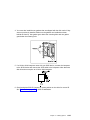
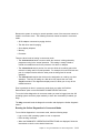
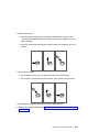
Using the Three–Button Mouse
The mouse is a hand–operated locating device. A three–button mouse is available
for use with the system unit.
Consult your application publication for the exact use of the three–button mouse.
You can use the mouse to perform such functions as positioning a cursor, selecting
items from a menu, or moving around in your document much easier and faster than
if you used only the keyboard. The cursor moves exactly as you move the mouse on
a flat surface, such as a desktop.
When you move the mouse around on a flat surface as shown in this illustration, the
cursor moves on the display screen; the movement changes the position of the
cursor.
With the mouse buttons, you can perform functions such as selecting and
deselecting options, extending your selection, or choosing a command. The precise
function of your mouse depends on the software you are using.
The mouse has a cable that plugs into the mouse connector at the rear of the
system unit.
Handling the Mouse Correctly
For best operation, handle the mouse with care. Incorrect handling can damage the
mouse.
Do not:
Operate the mouse on cloth, unfinished wood, newspaper, or carpet.
Drop or hit the mouse.
Carry the mouse by holding onto the cable.
Expose the mouse to extreme temperatures or direct sunlight.
Place the mouse in liquid spills.
Chapter 2. Using the System Unit
2-5
Care of the Mouse
The operating surface for the mouse should be smooth, clean, and flat. For
example, you can operate the mouse on the following surfaces:
Finished wood
Glass
Enamel
Plastic
Paper (except newspaper)
Metal
Rough surfaces collect contaminants that can be transferred to the interior of the
mouse by the ball. The surface you use should be free from spills, dirt, dust, lint,
wax, eraser dust, and other foreign matter. Rough surfaces can also cause the pads
located on the bottom of the mouse to prematurely wear. A deeply pitted surface
could cause erratic operation of the mouse.
Inspect the work surface for spills or other contaminants.
Dust the work surface.
If you are using a paper pad, inspect it for wear and replace it if necessary.
2-6
RS/6000 7025 F40 Series User's Guide
Cleaning the Mouse
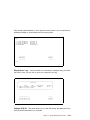
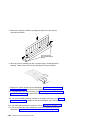
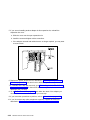
1. Remove the retaining ring by turning it counterclockwise, in the direction of the
arrow as shown in the illustration.
Retaining Ring
Ball
Cavity
2. Remove the ball.
3. Inspect the ball for contaminants. Wipe it clean with a dry, lint–free cloth.
4. If the ball is dirty, wash it in warm, soapy water. Rinse and wipe the ball with a
lint–free cloth until dry.
5. Inspect the ball cavity in the mouse for foreign materials. If there are any foreign
materials, remove them.
6. Replace the ball.
7. Replace the retaining ring on the mouse and align it with the open slots in the
ball cavity.
8. Turn the retaining ring clockwise until the open slots are covered and you hear
the ring snap into place.
Chapter 2. Using the System Unit
2-7
Using the 3.5–Inch Diskette Drive
Diskette Compatibility
The system unit has a 1.44MB diskette drive installed.
The 1.44MB diskette drive can format, read, and write diskettes compatible with the
following diskette drives:
1.0MB diskettes with 720KB formatted data capacity.
2.0MB diskettes with 1.44MB formatted data capacity (HD).
Format the diskette according to its specified capacity.
Write–Protecting 3.5–Inch Diskettes
Write–protecting diskettes is necessary so that important information is not
accidentally lost.
When diskettes are write–protected, you can read information from the diskettes, but
you cannot write information on to them.
There is a write–protect tab on the 3.5–inch diskette.
To locate the write–protect tab, turn the diskette over with the label facing down.
To prevent writing onto a diskette, slide the write–protect tab, to open the protect
slot.
(Slot Open)
Write-Protect Tab
2-8
RS/6000 7025 F40 Series User's Guide
To allow writing onto a diskette, slide the write–protect tab to cover the protect
slot.
(Slot Closed)
Write-Protect Tab
Loading and Unloading the 3.5–Inch Diskette
To load a diskette into the drive, insert the diskette in the diskette drive with the
labeled metal shutter first. Push the diskette into the drive until you hear a click.
The click indicates that the diskette is securely in position in the drive.
To unload the diskette, push the diskette–unload button. The diskette unloads
partially from the drive. Pull the diskette out.
Chapter 2. Using the System Unit
2-9
Using the CD–ROM Drive
CAUTION:
A Class 3 laser is contained in the device. Do not attempt to operate the device
while it is disassembled. Do not attempt to open the covers of the device, as it
is not serviceable and is to be replaced as a unit.
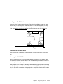
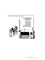
The CD–ROM is located in bay A1 of the system unit. Your CD–ROM drive looks like
the one shown in the illustration, and the controls are located as indicated.
When the CD–ROM is set to On, the status light indicates one of several conditions.
The following are status light states and the respective conditions of the CD–ROM
drive:
Off during standby with the tray loaded or unloaded.
Blinks from insertion of the tray to completion of initialization.
Blinks slowly when either the lens or disc is dusty (lens should be cleaned by
running the cleaning disc).
Blinks fast when in the audio mode.
Lights during data transfer operations.
Lights steady when:
– No disc is in the tray.
– The disc is in the tray upside down.
– Some condition exists that should be checked. If this occurs, contact your
service representative.
2-10
RS/6000 7025 F40 Series User's Guide
Loading the CD–ROM Drive
Press the unload button to open the tray. Place the disc, with the printed side away
from the tray, into the tray. If the CD–ROM drive is in the vertical position, slip out
the bottom tabs to hold the disc in place. Push gently on the load/unload button. The
drive automatically pulls the tray into the drive and prepares the disc for reading.
Unloading the CD–ROM Drive
Push and hold the unload button until the drawer comes out and then remove the
disc.
Cleaning the CD–ROM Drive
This CD–ROM drive has an internal head–cleaning mechanism, and therefore does
not require an external cleaning device. The internal cleaning mechanism cleans the
head every time the tray is operated.
Always handle discs carefully by the edges to avoid leaving fingerprints or scratching
the disc. (This helps the disc to maintain good readability.) Discs can be wiped with a
soft, lint–free cloth or lens tissue. Always wipe in a straight line from the inner hub to
the outer rim.
Chapter 2. Using the System Unit
2-11
Emergency Eject
Note: Execute the following procedure only in an emergency (caddy will not eject
although pressing the unload button).
1. Insert a small diameter rod, such as a straightened paper clip, into the
emergency eject hole. (Refer to the illustration below for the location of the
emergency eject hole.)
2. Push the tool in until some resistance is felt.
3. Maintain a small amount of pressure on the rod while pulling on the tray with
your finger nail.
4. Pull the tray open and remove the disc.
Note: Normally the tray makes a ratcheting sound when pulling it open using the
above procedure.
2-12
RS/6000 7025 F40 Series User's Guide
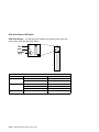
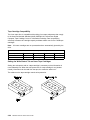
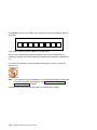
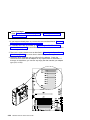
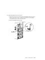
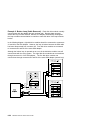
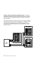
Using the Hot Swap Disk Drives
For information on installing SCSI hot swap drives refer to “Installing a Hot-Swap
SCSI Disk Drive in Bank C, D, or E.” on page 4-48.
For information on installing SSA hot swap drives refer to “Installing a Hot-Swap SSA
Disk Drive in Bank C, D, or E” on page 4-52.
For information on removing SCSI hot swap drives refer to “Removing a Hot-Swap
SCSI Disk Drive from Bank C, D, or E” on page 4-80.
For information on removing SSA hot swap drives refer to “Removing a Hot-Swap
SSA Disk Drive from Bank C, D, or E” on page 4-84
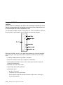
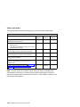
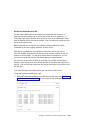
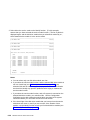
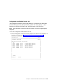
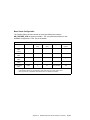
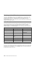
Relationship of AIX Prompts and Physical Drive Location
A SCSI adapter and a SCSI drive address can be displayed on a user display. The
AIX command lscfg lists the attached devices on the system display. A SCSI
adapter and drives might be listed as:
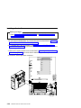
Labels on the right side of each bank, identify the PCI Bus indicator and PCI Slot
address for the SCSI adapter attached to each bank.
Physical Slot of SCSI Adapter
Bank Label
9I/P
04 - 09
8I/P
04 - 08
7P
04 - 07
6P
04 - 06
5P
04 - 05
4P
04 - 04
3P
04 - 03
2P
04 - 02
1P
04 - 01
Second Integrated SCSI Controller
04 - F0
First Integrated SCSI Controller
04 - E0
Chapter 2. Using the System Unit
2-13
2-14
RS/6000 7025 F40 Series User's Guide
Handling Guidelines
The hot-swap disk drive is a sensitive device. Handle the hot-swap carrier and disk
drive with care.
Do not drop the disk drive or subject the drive to excessive shock.
Do not expose the disk drive to temperatures lower than -40° F (-40° C) or
higher than 158 ° F (70° C).
If drive temperature changes, allow approximately one hour of temperature
acclimatization for every 18° F (10° C) of temperature change.
Never allow moisture to condense on the drive.
Static electricity can damage your equipment. Take these precautions to avoid
static electricity damage:
– Always handle your disk drive carefully.
– Handle the drive by the edges and never touch any exposed circuitry.
– Prevent others from touching the drive.
Store the hot-swap disk drive in a protective container such as an instrument
case or in a protected area.
Failure to observe these precautions may lead to product failure, damage, and
invalidation of all warranties.
Labels
Several labels are included in your system ship group which may be attached to the
handle of the hot-swap drive. The labels may be marked in any way that the user
can easily identify the drive for removal or installation.
Chapter 2. Using the System Unit
2-15
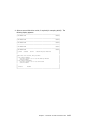
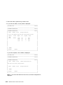
Disk Drive Status LED States
SCSI Disk Drives: The following table explains the meaning of the green and
amber status LEDs and spin down button.
Status LEDs
LED or Button
Status
Definition
Amber
On
Drive spinning
Off
Drive not spinning
On
Power On
Off
Power Off
Blinking
Power Off/Drive identify
Depressed
Spin down drive and remove power
Green
Spin down
2-16
RS/6000 7025 F40 Series User's Guide
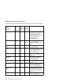
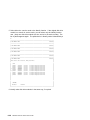
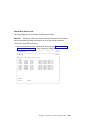
SSA Disk Drives: The following table explains the meaning of the Power, Ready
and Check status LEDs.
Status LEDs
LED
Status
Definition
Power
On
Power On
Off
Power Off
On
Both SSA connections good and
drive is ready
Blinking
Only one SSA connection good
Flickering
Drive is executing a command
On
Disk drive failure
Ready
Check
Self-test running
Drive in service mode
Blinking
Disk drive selected
Chapter 2. Using the System Unit
2-17
General Information for 5.0GB 8-mm Tape Drive
Requirements
The 5.0GB 8-mm Tape Drive requires that firmware version TR97038 or later be
installed in your system unit. To check the level of firmware installed, see Chapter 3,
“System Management Services” on page 3-1.
Recommendations
Use only Data Grade 8-mm tape cartridges. These cartridges are identified by
either a Data, D, or D8 marking on the data cartridge. Use of video grade
cartridges can damage the 8-mm tape drive and can void the warranty of your
8-mm tape drive, and data written on these tapes may be lost over a short period
of time.
Remove the tape cartridge from the tape drive when it is not in use, and store
the cartridge in the cartridge case.
Do not open the door on the data tape cartridge. This door covers and protects
the magnetic tape material from dirt, dust, and damage.
Avoid touching the tape since this can cause loss of data.
Keep the tape drive door closed except when loading or unloading a tape
cartridge.
Back up and then discard any tape cartridge that repeatedly produces error
messages. The error information is in the system error log.
Clean the tape path regularly according to the cleaning procedure of the 8-mm
tape drive. Use only recommended cleaning cartridges; other cleaning cartridges
can permanently damage your 8-mm tape drive.
Attention: Do not use video grade cartridges in the 8-mm tape drive. Video grade
tapes may be unreliable and may cause permanent damage to the 8-mm tape drive.
Types of 8-mm Tape Cartridges
Test Tape Cartridge: This is a specially labeled tape cartridge that is in the
media kit with the 8-mm tape drive. Use this cartridge only when checking the
operation of the drive or running diagnostics; do not use it to save programs or
data.
Data Tape Cartridge: This is a non-labeled blank tape cartridge that is in the
media kit. Use this cartridge for saving your programs or data. The same data
tape cartridge can be used in either a 2.3GB 8-mm tape drive or a 5.0GB 8-mm
tape drive.
2-18
RS/6000 7025 F40 Series User's Guide
Cleaning Tape Cartridge: Use this cartridge for cleaning the 8-mm tape path. For
more information, see “Cleaning the Tape Path on the 5.0GB 8-mm Tape Drive”
on page 2-26.
Chapter 2. Using the System Unit
2-19
Tape Cartridge Compatibility
The 8-mm tape drive is compatible with existing 8-mm tape subsystems that comply
to the American National Standard (ANSI) X3B5/89-136, Helical-scan Digital
Computer Tape Cartridge, 8-mm for Information Exchange. Data compression
effectively increases the cartridge capacity and data transfer rate for the 5.0GB tape
cartridges.
Note: 160 meter cartridges are not processed and are automatically ejected by the
drive.
Format Modes (C=compression mode)
8-mm Tape Drive
2.3GB
2.3GB
Read/Write
5.0GB
Read/Write
2.3GB (C)
5.0GB
5.0GB (C)
Read only
Read/Write
Read/Write
Setting the Write-Protect Tab on 8-mm Tape Cartridges
Setting the write-protect tab on a tape cartridge is necessary so that information is
not accidentally lost. When the write-protect tab of a tape cartridge is set (window
closed), information can be read from the tape, but cannot be written to it.
The window on the tape cartridge controls write-protection.
2-20
RS/6000 7025 F40 Series User's Guide
Environment Considerations for 8-mm Data Cartridges
Information in this section describes operating and storage conditions including
temperature, relative humidity, and maximum wet bulb data.
Attention: The manufacturer has specified a set of temperature and humidity
ranges in which the 8-mm data cartridge can operate with ease. Only regular
cleaning procedures are required when operating the cartridge within this range. The
risk of possible data loss is increased if 8-mm tape cartridges are operated, stored,
or shipped outside the temperature or humidity ranges shown in the following table.
Before using a cartridge, always let it adjust (acclimate) to the operating
environment. Do this by placing the cartridge with its container in the operating
environment for as long as it has been away from this environment or for 24 hours,
whichever is less.
Acclimation is necessary for any data cartridge that has been exposed to a different
humidity environment or a temperature change of 11°C or 20°F or more.
Temperature
Relative Humidity
(non-condensing)
Maximum Wet Bulb
Operating Ranges
Storage
Shipping
16°C to 32°C
(60°F to 90°F)
20 to 80%
5°C to 32°C
(40°F to 90°F)
20 to 80%
-40°C to 52°C
(-40°F to 125°F)
5 to 80%
26°C (79°F)
26°C (79°F)
26°C (79°F)
Chapter 2. Using the System Unit
2-21
Operating in Harsh Environments
The 8-mm tape drive is ideally suited to streaming operations, as opposed to tape
movement operations involving multiple stop/starts and random searches. When the
tape is used for frequent stop and start operations, streaming movement is beneficial
and should be used whenever possible. This can be accomplished by ensuring that
any save or restore operation is the only active operation performed by a device
connected to this SCSI I/O controller.
Any tape that has been used outside the ranges specified in the table on 2-21 for an
extended period of time (50 passes in 40 hours of nonstop operation) should not be
used as an archival tape. Exposure to the environment will deteriorate the magnetic
and physical strength of the tape. Do not store important data on a tape that has
been used outside the specified ranges; transfer the data to a new tape for reliable
archiving.
8-mm Data Cartridge Erasure
Most bulk eraser devices do not have the capability to erase 8-mm data cartridges.
To properly erase an 8-mm data cartridge with a bulk eraser device, the erasure
rating must be at least 1500 oersted.
The 2.3GB and the 5.0GB 8-mm tape drives erase residual data before writing new
data on the data tape.
Tape Cartridge Data Efficiency
The 8-mm tape cartridge efficiency is defined as the amount of data that can be
stored on the cartridge. The following variables affect the amount of data that can be
stored on a tape cartridge:
Size of the data file
Number of file marks per file
File mark size used
Compatibility mode (2.3GB or 5.0GB)
Media rewrites.
2-22
RS/6000 7025 F40 Series User's Guide
Using the 5.0GB 8-mm Tape Drive
The optional 5.0GB 8-mm tape drive is a half-height device.
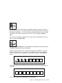
Status Lights
The 5.0GB 8-mm tape drive has two green status lights and one amber status light.
The on and off combinations of the status lights indicate the conditions of the 8-mm
tape drive.
Each of the International Organization for Standards (ISO) symbols located next to a
status light indicates a specific condition of the tape drive as follows:
Status Lights
Unload Button
Disturbance - Amber
Ready Green
Busy - Green
Chapter 2. Using the System Unit
2-23
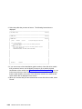
Status Light States
The following table explains the meaning of the green and amber status lights.
Status Lights on the 5.0GB 8-mm Tape Drive
Status
Ready
(green)
Busy
(green)
Disturbance
(amber)
The power-on self-test (POST) is running or the system
has issued a Reset to the drive.
On
On
On
One of the following has occurred:
Off
Off
Off or On
A tape cartridge has been inserted and the 8-mm tape
drive is ready to receive commands from the system.
On
Off
Off or On
A tape cartridge has been inserted and the 8-mm tape
drive is performing a tape load or unload operation.
Off
Flashing
Off or On
The tape is in motion and the 8-mm tape drive is busy
running a device operation.
On
Flashing
Off or On
The 8-mm tape drive has detected an internal fault that
requires corrective action. If this occurs, see the
following note.
Off
Off
Flashing
The tape path requires cleaning. Refer to “Cleaning the
Tape Path on the 5.0GB 8-mm Tape Drive” on
page 2-26.
Off or On
Off or
Flashing
On
The power is off.
The POST has completed successfully, but no tape
cartridge has been inserted.
Note: If a fault or an error condition occurs, first try to recover by pressing the
unload button. If this does not correct the fault, switch off the power to the 8-mm
tape drive and then switch on the power to the drive. If the condition continues, call
your service representative.
2-24
RS/6000 7025 F40 Series User's Guide
Loading the 8-mm Tape Cartridge
Before loading the tape cartridge, make sure the power is on and the write-protect
tab on the tape cartridge is properly set. Refer to “Setting the Write-Protect Tab on
8-mm Tape Cartridges” on page 2-20. The tape drive loads the tape from the
cartridge and prepares it for reading and writing.
To load the 8-mm tape cartridge, do the following:
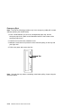
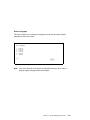
1. Grasp the edges of the 8-mm tape cartridge with the write-protect tab toward you
and the window side of the cartridge facing up.
2. Slide the tape cartridge into the opening on the front of the 8-mm tape drive until
the loading mechanism pulls the cartridge into the drive and the drive door
closes. The ready status light (green) goes on if the load operation was
successful.
Window Side of
Tape Cartridge
8-mm Tape Cartridge
Write-Protect Tab
Ready Status
Light (Green)
The 8-mm tape drive is ready for data operations when the tape cartridge is inserted.
After the cartridge is inserted into the tape drive, the tape takes about 25 seconds to
load; this does not interfere with beginning the data operations.
Commands can be entered while the tape is loading. Any commands to the tape
drive start running once the tape has finished loading. Commands not requiring the
tape cartridge are run immediately.
Chapter 2. Using the System Unit
2-25
Unloading the 8-mm Tape Cartridge
Before performing the unload operation, make sure the power to the 8-mm tape drive
is on.
To unload and eject the tape cartridge, press the unload button. The 8-mm tape
drive rewinds the tape and then ejects the tape cartridge from the tape drive.
After pressing the unload button, the following occurs:
1. The ready status light goes off.
2. The busy status light flashes during the unload operation.
3. The busy status light will goes off when the cartridge is ejected from the tape
drive.
8-mm Tape Cartridge
Status
Unload Button
Write-Protect Tab
Disturbance - Amber
Ready - Green
Busy - Green
The time required for a tape to rewind and unload is between 18 seconds and 3
minutes, depending on the position of the tape when the unload button is pushed.
If the tape cartridge cannot unload and has to be removed manually from the drive,
contact your service representative.
Cleaning the Tape Path on the 5.0GB 8-mm Tape Drive
Attention: Do not use video cleaning cartridges in the 8-mm tape drive. Video
cleaning cartridges can damage the 8-mm tape drive.
The 8-mm tape path should be cleaned either approximately every 30 hours of tape
motion or once a month, whichever occurs first. The 5.0GB 8-mm tape drive counts
the number of hours of tape motion and indicates when the tape path requires
cleaning when the lighted disturbance status light (amber) is on.
More frequent cleaning may be required if the drive is operated in a dusty
environment or in humid conditions. If the dust is allowed to accumulate, the drive
2-26
RS/6000 7025 F40 Series User's Guide
has to perform more reads and writes. This can cause data loss, and may be
prevented by regularly scheduled cleaning of the drive.
The cleaning cartridge cleans the 8-mm tape drive. If you attempt to use an 8-mm
cleaning cartridge more times than allowed, the tape drive automatically detects the
error and ejects the cleaning cartridge. The disturbance status light (amber) remains
on if it was on prior to the cleaning operation being attempted.
Some video cleaning cartridges are extremely abrasive. An 8-mm tape drive may be
permanently damaged after only a few cleaning operations using an abrasive-type
cleaning cartridge.
Before loading the cleaning cartridge, make sure the power to the 8-mm tape drive is
on.
To load the 8-mm cleaning cartridge, do the following:
1. Grasp the edges of the 8-mm cleaning cartridge with the window side of the
cartridge facing up.
2. Slide the cleaning cartridge into the opening on the front of the 8-mm tape drive
until the loading mechanism pulls the cartridge into the drive.
8-mm Tape Cartridge
Window Side of
Tape Cartridge
Status
Disturbance - Amber
Ready - Green
Busy - Green
After the 8-mm cleaning cartridge has been fully inserted into the 8-mm tape drive,
the following cleaning operations are performed automatically:
1. The cleaning tape is loaded into the tape path.
2. The drive is cleaned by moving the cleaning tape forward for approximately two
minutes.
3. The tape is unloaded and the cleaning cartridge is ejected from the tape drive
when the cleaning operation is complete.
4. A successful cleaning operation is indicated when the disturbance status light
(amber) goes off.
Chapter 2. Using the System Unit
2-27
General Information for 4.0GB 4-mm Tape Drive
The 4.0GB 4-mm tape drive is a streaming tape drive that is used to:
Save and restore system data files.
Archive important records.
Distribute operating system software upgrades.
The 4-mm tape drive can be attached to any system using a single-ended interface
meeting the Small Computer System Interface ll (SCSI-ll) Standard ANSI
X3.131-199X Rev. 10h.
The 4-mm tape drive has the following features:
Capacity of 4.0 GB per cartridge. 8 GB is typical with data compression and with
DDS2 data cartridges.
The actual capacity per cartridge varies depending on the application and the
type of data cartridge being used.
Data transfer rate is 400 KBps. 800 KBps is typical with data compression.
Note: Data compression activated is the default setting from the factory. Data
compression is usually controlled by the application software.
Read and write of DDS|||| tape cartridges in 2.0 GB per cartridge format.
A status light that indicates when it is time to clean the tape path.
Internal diagnostics that are activated when the 4 mm Diagnostic Cartridge is
inserted and loaded into the drive.
Media recognition system: only data grade media can be written with this tape
drive.
The 4-mm tape drive uses a 4-mm data cartridge for saving and restoring your
system data. The 4-mm tape drive writes and reads only 4-mm Digital Data Storage
(DDS|||| or DDS2) cartridges.
2-28
RS/6000 7025 F40 Series User's Guide
Recommendations
Attention: Tape cartridges that do not carry the proper DDS symbol cannot be
written to and their use may cause the 4-mm tape drive to report an error.
Use only 4-mm Digital Data Storage (DDS|||| or DDS2) cartridges.
Attention: Use of other than recommended cleaning cartridges can damage
your tape drive and will void the drive warranty.
Clean the tape path by using the recommended cleaning cartridge. Follow the
instructions on the cartridge.
Back up and then discard any tape cartridge that repeatedly produces error
messages. The error information is in the system error log.
Do not open the door on the data cartridge that covers the tape. This door
protects the magnetic tape material from dirt, dust, and damage.
Do not operate in a dusty environment.
Do not touch the tape material. Any substance transferred to the tape by
touching it could cause loss of data.
Types of 4-mm Tape Cartridges
The 4-mm tape drive is shipped with three 4-mm cartridges to help start your tape
operations immediately.
4-mm Data Cartridge:
Use this non-labeled cartridge for saving or
restoring your programs or data. Additional data
cartridges can be ordered.
4-mm Diagnostic Cartridge:
Use this specially labeled cartridge to perform
diagnostics on the drive. Do not use it to save or
restore programs or data.
Cleaning Cartridge:
Use this cartridge for cleaning the 4-mm tape path.
For more information, see “Cleaning the Tape Path
on the 4.0GB 4-mm Tape Drive” on page 2-37.
Chapter 2. Using the System Unit
2-29
Tape Cartridge Compatibility
The 4-mm Tape Drive is compatible with existing 4mm tape subsystems that are
designed to operate with Digital Data Storage approved media, which meet the
following standards:
For DDS||||
– American National Standard (ANSI) standard, X3.203-191, Helical-scan
Digital Computer Tape Cartridge, 3.81mm.
– European Computer Manufacturers Association (EMCA) standard,
EMCA-150 , 3.81mm Wide Magnetic Tape Cartridge and DDS|||| format.
For DDS2
– European Computer Manufacturers Association (EMCA) standard,
EMCA/TC17/93/20, 3.81mm Wide Magnetic Tape Cartridge for Information
Interchange Helical Scan Recording, DDS2 format.
You cannot change the density setting of the drive, because the device reconfigures
itself automatically, depending on the media type installed, as follows:
Media Type
Device Configuration
Non-DDS
Read-only
DDS||||
Read/write in 2.0GB mode only.
DDS2
Read in either density; write in 4.0GB mode only.
2-30
RS/6000 7025 F40 Series User's Guide
Setting the Write-Protect Tab on 4-mm Tape Cartridges
The window on the tape cartridge controls write-protection. When the write-protect
tab of a tape cartridge is set (window open), information can be read from the tape,
but cannot be written to it. When the write-protect tab of a tape cartridge is not set
(window closed), information can be both written to and read from the tape. Trying to
write to a 4-mm data cartridge with the window open causes an error.
Chapter 2. Using the System Unit
2-31
Environmental Considerations for 4-mm Data Cartridges
Information in this section describes operating and storage conditions including
temperature, relative humidity, and maximum wet bulb data.
Attention: The manufacturer has specified a set of temperature and humidity
ranges in which the 4-mm data cartridge can operate with ease. Only regular
cleaning procedures, as described in “Cleaning the Tape Path on the 4.0GB 4-mm
Tape Drive” on page 2-37 are required when operating the cartridge within this
range. The risk of possible data loss is increased if 4-mm tape cartridges are
operated, stored, or shipped outside the temperature or humidity ranges shown in
the following table.
Before using a cartridge, always let it adjust (acclimate) to the operating
environment. Do this by placing the cartridge with its container in the operating
environment for as long as it has been away from this environment or for 24 hours,
whichever is less.
Acclimation is necessary for any data cartridge that has been exposed to a different
humidity environment or a temperature change of 11°C or 20°F or more.
Temperature
Relative Humidity
(non-condensing)
Maximum Wet Bulb
2-32
Operating Ranges
Storage
Shipping
16°C to 32°C
(60°F to 90°F)
20 to 80%
5°C to 32°C
(40°F to 90°F)
20 to 80%
-40°C to 52°C
(-40°F to 125°F)
5 to 80%
26°C (79°F)
26°C (79°F)
26°C (79°F)
RS/6000 7025 F40 Series User's Guide
Operating in Harsh Environments
The 4-mm tape drive is ideally suited to streaming operations, as opposed to tape
movement operations involving multiple stop/starts and random searches. When the
tape is used for frequent stop and start operations, streaming movement is beneficial
and should be used whenever possible. This can be accomplished by ensuring that
any save or restore operation is the only active operation performed by a device
connected to this SCSI I/O controller.
Any tape that has been used outside the ranges specified in the previous table for an
extended period of time (50 passes in 40 hours of nonstop operation) should not be
used as an archival tape. Exposure to the environment will deteriorate the magnetic
and physical strength of the tape. Do not store important data on a tape that has
been used outside the specified ranges; transfer the data to a new tape for reliable
archiving.
4-mm Data Cartridge Erasure
Most bulk eraser devices do not have the capability to erase 4-mm data cartridges.
To properly erase an 4-mm data cartridge with a bulk eraser device, the erasure
rating must be at least 2000 oersted.
The 4-mm tape drive erases residual data before writing new data on the data tape.
Tape Cartridge Data Capacity
The 4-mm tape cartridge capacity is defined as the amount of data that can be
stored on the cartridge. The following variables affect the amount of data that can be
stored on a tape cartridge:
Size of the data file
Number of file marks per file
Compatibility mode (2GB or 4GB)
Media rewrites.
Chapter 2. Using the System Unit
2-33
Using the 4.0GB 4-mm Tape Drive
The optional 4.0GB 4-mm tape drive is a half-high device.
Status Lights
The 4.0GB 4-mm tape drive has two green status lights and one amber status light.
The on and off combinations of the status lights indicate the conditions of the 4-mm
tape drive.
Each of the International Organization for Standards (ISO) symbols located over a
status light indicates a specific condition of the tape drive as follows:
4-mm Tape (Front View)
Tape Drive Door
Ready (Green)
Read/Write (Green)
Disturbance (Amber)
2-34
RS/6000 7025 F40 Series User's Guide
Status Lights
Unload Button
Status Light States
The following tables explain the meaning of the green and amber status lights.
Ready (green)
Read-Write (green)
Disturbance (amber)
Off
No cartridge installed or
error condition
No cartridge or no
activity
No error condition
Steady
Cartridge installed or
loading/unloading
Flashing
Power-on self- test in
progress
Cleaning required or
worn media
Cartridge activity
Error condition
Status Lights on the 4.0GB 4-mm Tape Drive
Status
Ready
(green)
Read-Write
(green)
Disturbance
(amber)
LED test.
On 2
seconds
at power
on
On 2
seconds
at power
on
On 2
seconds
at power
on
The power-on self-test (POST) is running or the
Diagnostic Cartridge is running.
Flashing
Off
Off
One of the following has occurred:
Off
Off
Off or On
A tape cartridge has been inserted and the 4-mm Tape
Drive is Ready to receive commands from the system.
On
Off
Off or ON
The tape is in motion and the 4-mm Tape Drive is
running a device operation or cleaning.
On
Flashing
Off or On
The 4-mm Tape Drive has detected an internal error
that requires corrective action such as tape cartridge
failure, high humidity, or no SCSI terminator. Refer to
the service guide or contact your service representative.
(See note below)
Off
Off
Flashing
The tape path requires cleaning or a poor quality tape
cartridge is being used. See “Cleaning the Tape Path
on the 4.0GB 4-mm Tape Drive” on page 2-37.
Off or On
Off or
Flashing
On
The power is off.
The POST has completed successfully, but no tape
cartridge has been loaded.
Note: If an error condition occurs, first try to recover by pressing the unload button.
If this does not correct the error, switch off the power to the 4-mm tape drive and
then switch on the power to the drive. If the condition continues, call your service
representative.
Chapter 2. Using the System Unit
2-35
Loading the 4-mm Tape Cartridge
Before loading the tape cartridge, make sure the power is on and the write-protect
switch on the tape cartridge is properly set. Refer to “Setting the Write-Protect Tab
on 4-mm Tape Cartridges” on page 2-31. The tape drive loads the tape from the
cartridge and prepares it for reading and writing.
To load the 4-mm tape cartridge, do the following:
1. Grasp the edges of the 4-mm tape cartridge with the write-protect tab towards
you and the window side of the cartridge facing up.
2. Slide the tape cartridge into the opening on the front of the 4-mm tape drive until
the loading mechanism pulls the cartridge into the drive and the drive door
closes. The ready status light (green) goes on if the load operation was
successful.
Window Side of
Tape Cartridge
Ready Status
Light (Green)
4 mm Tape Cartridge
Write-Protect Tab
Unload Button
The 4-mm tape drive is ready for data operations when the tape cartridge is inserted.
After the cartridge is inserted into the tape drive, the tape takes about 15 seconds to
load.
2-36
RS/6000 7025 F40 Series User's Guide
Unloading the 4-mm Tape Cartridge
Before performing the unload operation, make sure the power to the 4-mm tape drive
is on.
To unload and eject the tape cartridge, press the unload button. The 4-mm tape
drive rewinds the tape and then ejects the tape cartridge from the tape drive.
After pressing the unload button, the following occurs:
1. The Read-Write status light flashes during the unload operation.
2. The Ready status light and the Read-Write status light turns off when the
cartridge is ejected from the tape drive.
Write-Protect Tab
4 mm Tape Cartridge
Ready Status
Light (Green)
Ready-Write Status
Light (Green)
Unload Button
The time required for a tape to rewind and unload is between 10 seconds and 1.5
minutes, depending on the position of the tape when the unload button is pushed.
If the tape cartridge cannot unload and has to be removed manually from the drive,
contact your service representative.
Cleaning the Tape Path on the 4.0GB 4-mm Tape Drive
The 4-mm tape path should be cleaned either approximately every 30 hours of tape
motion or once a month, whichever occurs first. The 4-mm tape drive monitors the
recording quality of the tape cartridge and indicates that the tape path requires
cleaning when the disturbance status light (amber) is on.
More frequent cleaning may be required if the drive is operated in a dusty
environment or in humid conditions. If the dust is allowed to accumulate, the drive
has to perform more reads and writes. This can cause data loss, and may be
prevented by regularly scheduled cleaning of the drive.
Chapter 2. Using the System Unit
2-37
The cleaning cartridge cleans the 4-mm tape drive 50 times before it needs to be
discarded. If you attempt to use a 4-mm cleaning cartridge more than 50 times, the
tape drive automatically detects the error and ejects the cleaning cartridge with the
disturbance status light (amber) remaining on.
Before loading the cleaning cartridge, make sure the power to the 4-mm tape drive is
on.
To load the 4-mm cleaning cartridge, do the following:
1. Grasp the edges of the 4-mm cleaning cartridge with the window side of the
cartridge facing up.
2. Slide the cleaning cartridge into the opening on the front of the 4-mm tape drive
until the loading mechanism pulls the cartridge into the drive.
Window Side of
Cleaning Cartridge
Disturbance Status
Light (Amber)
4 mm Cleaning Cartridge
Unload Button
After the 4-mm cleaning cartridge has been fully inserted into the 4-mm tape drive,
the following cleaning operations are performed automatically:
1. The cleaning tape is loaded into the tape path.
2. The drive is cleaned by moving the cleaning tape forward for approximately 30
seconds.
3. The tape is unloaded and the cleaning cartridge is ejected from the tape drive
when the cleaning operation is complete.
4. A successful cleaning operation is indicated when the disturbance status light
(amber) goes off (if it was activated before the cleaning operation).
If the cleaning cartridge has been used more than 50 times the disturbance status
light (Amber) will flash.
2-38
RS/6000 7025 F40 Series User's Guide
Using the 24/48GB DDS-2 4-mm Tape Autoloader
There are two versions of the 4-mm Tape Autoloader. One is vertically oriented and
the other is horizontally oriented. Your system type determines which version you
use. Both versions operate the same although the front bezel is labeled vertically or
horizontally. The vertical version is shown.
Attention: Never remove, install, or transport the 4-mm Tape Autoloader with tape
cartridges loaded in the drive. They can become dislodged and jam the mechanism.
Controls and Indicators
Select Button: The Select button allows you to select a cartridge from the
magazine in the unit. The number of the cartridge selected is displayed on the left
side of the LCD. If you press the Select button repeatedly, the display cycles
through the cartridges available in the magazine.
Chapter 2. Using the System Unit
2-39
Eject Button: The Eject button starts the unload process. The drive unloads any
currently loaded cartridge, and the changer mechanism returns it to the magazine.
The magazine is then ejected.
Load Tape Button: The Load Tape button loads the selected cartridge from the
magazine into the drive. The drive then goes into sequential mode. See “Modes” on
page 2-45.
Note: When in Random Mode, the select and load buttons are disabled. Their
function is controlled by host software.
Magazine Present (LED)
Steady Green: A magazine is in the Autoloader.
Flashing Green: A magazine is being loaded, checked, or ejected.
Tape Activity (LED): This light indicates what is happening to the cartridge in the
drive:
Steady Green: A cartridge is present in the drive
Rapidly Flashing (twice per second) Green: Data is being read or written
Slowly Flashing (once per second) Green: A cartridge is being loaded or
unloaded.
Operator Attention Required (LED): This light indicates that the operator
needs to take some action:
Steady Amber: A serious hardware error has occurred. If a power reset does not
eliminate the problem, the Tape Autoloader requires service.
Flashing Amber: A user-recoverable error has occurred:
– The front-panel door is open.
– A cartridge is in the drive, but no magazine is present.
– The tape heads need cleaning.
– The tape is nearing the end of its useful life.
– A firmware upgrade is occurring.
When the Operator Attention Required LED is on or flashing, an error message
might be displayed in the Status LCD.
2-40
RS/6000 7025 F40 Series User's Guide
Status Liquid Crystal Display
The Status LCD displays a range of autoloader status information in each of its five
display regions:
1 A 10-character display provides operating status information and potential
error conditions.
2 A 7-segment display shows the number of the cartridge currently loaded in
the drive, or the cartridge selected when the Select button is pressed repeatedly.
3 "DC" indicates that data compression is being used for writing; "WP"
indicates a Write-Protected cartridge.
4 Six numbered boxes individually light to show which magazine slots contain
a cartridge.
5 An "odometer" line shows how much tape has been used in the active
partition of the current cartridge. The more lines that are shown, the more tape
that has been used.
Chapter 2. Using the System Unit
2-41
Loading a Magazine
Attention: Cartridge and magazine labels must be firmly affixed to the recessed
label areas; otherwise, the mechanism will jam.
Labels must not be peeling off.
Labels must not go over the edge of the label area.
Labels must not be folded over the edge of cartridges.
Labels must not be stuck on top of another label.
Attention: Only cartridges labeled with the DDS or DDS2 logo should be used in the
Autoloader.
It is recommended that you store cartridges in their magazines, so that cartridges
belonging to a multi-volume backup are kept together and in the correct order.
1. Align the arrow on the cartridge with the arrow on the magazine and insert the
cartridge in the magazine. Insert as many cartridges as you need. You can
insert up to 6 cartridges, and they can be placed in any of the magazine slots.
2-42
RS/6000 7025 F40 Series User's Guide
2. Insert the cartridge magazine into the slot in the front of the Autoloader with the
large arrow on the magazine pointing towards the Autoloader. Apply steady
pressure until the mechanism takes the magazine and pulls it into the
Autoloader.
Ejecting a Magazine
To eject the magazine, press the Eject button. When you do this:
1. The tape rewinds to the beginning of the partition (BOP).
2. If the tape is write-enabled, the updated copy of the Tape log is written back to
tape.
3. The tape rewinds to BOM and is unthreaded.
4. The changer replaces the cartridge in the magazine.
5. The magazine is ejected.
Chapter 2. Using the System Unit
2-43
Forcing an Ejection
Attention: Force an ejection only as a last resort to recover a cartridge. Never use it
as a quick way of ejecting the cartridge. You can lose data if you force an eject.
The tape also might end up invalidly formatted, because EOD might not have been
written.
If you press the Eject button when the drive is busy, the drive first completes the
current task. Then it responds to the ejection request. This ensures that the task is
terminated in a controlled manner and that no data is lost.
There might be occasions when you need to unload a cartridge urgently, even at the
risk of losing data. To do this, you must force an ejection:
1. Press and hold the Eject button for at least 5 seconds. The LCD displays "Force
Eject."
2. The Autoloader waits 35 seconds to give the normal ejection process a chance
to occur.
3. When this period elapses, any tape in the drive is immediately unthreaded, and
the cartridge is ejected, regardless of what operation the drive was performing.
The cartridge then is returned to its slot in the magazine, and the drive is reset
as though power had been cycled. Because forced ejection might interrupt an
operation, it is possible that the drive will not write EOD before the cartridge is
ejected. This will cause a loss of data and an invalid formatting of the cartridge.
The data on such a cartridge should be readable up to the point where the
format violation occurred.
4. If no cartridge is loaded in the drive, the Autoloader waits 35 seconds, ejects the
magazine, and then resets as though power had been cycled.
2-44
RS/6000 7025 F40 Series User's Guide
Modes
The Autoloader can operate in two modes, sequential or random.
Sequential: In sequential mode, the Autoloader does not depend on host
implementation of changer commands. You select which cartridge you want to start
with by using the Select and Load buttons on the front panel. When a cartridge is
ejected from the drive following a host UNLOAD command, the cartridge is placed
back in it's slot and the the Autoloader automatically loads the next available
cartridge from the magazine into the drive.
Random: In random mode, the host views the Autoloader as two devices:
A changer mechanism to which SCSI Medium Changer commands can be sent.
A tape drive to which SCSI Sequential Access commands can be sent.
The controlling host computer therefore has full random access to any cartridge.
Most backup/restore applications automatically load, unload the Autoloader using the
random access mode. Refer to your backup/restore software instructions for
additional details.
Loading and Unloading Cartridges
When a magazine containing cartridges has been inserted into the autoloader, some
applications can begin, because they use the Move Medium commands which can
select and load cartridges. However, many applications, and the AIX commands
mksysb, tar, backup, cpio, operate only with a tape drive which has media loaded
(is Ready). Also, the drive must be loaded with an appropriate cartridge to boot from
the drive, or to run diagnostics on the drive. You can load the drive manually using
the controls on the front of the Autoloader.
To load a cartridge into the tape drive contained in the Autoloader, you use the
Select button on the front of the Autoloader to select one of the cartridges from the
magazine. Then, pressing the Load Tape button causes the selected cartridge to be
moved from the magazine to the drive, where the drive starts a Load cycle
automatically. Pressing the Load Tape button when the Select digit is "0" causes the
loading of the first available cartridge in the magazine.
The tape drive may encounter difficulties in loading the cartridge. If it does, AIX and
most using applications are unaware of the difficulty because applications and AIX
typically communicate with "Ready" devices. You should observe the loading process
to ensure it completes successfully. If the Load Tape process fails, the Autoloader
retries the cycle several times. Failure to load after retrying is signaled to the
Chapter 2. Using the System Unit
2-45
operator through the LCD panel and Operator Attention Required LED on the control
panel.
Load failures are indicated by a flashing (Yellow) Operator Attention Required LED
and messages on the LCD. If an error message (for example, Error 112) is displayed
alternating with the instruction PressEject, the operator should press the Eject button
which causes the magazine to be ejected with the unloadable cartridge. Try another
cartridge. If a second cartridge also fails to load, the drive may be defective.
However, if a substitute cartridge loads successfully, the original cartridge may be
defective. You can try to load it into another 4-mm tape drive, or examine it for
obvious problems (such as tape disconnected from one of the reels).
When a cartridge has been loaded, the LCD displays the READY message, and the
application, diagnostic, or command can be initiated or continued. On initial manual
loading, the Autoloader is in a sequential mode. In this mode, an Unload command
issued to the drive causes the cartridge to be placed back in its assigned slot in the
magazine and the next available cartridge to be loaded. This process ends when the
cartridge in the highest numbered occupied slot of the magazine has been
processed.
Most AIX commands such as mksysb, tar and backup do not issue Unload
commands at the end of the command or at the end of the tape. When not
controlled by the command or application, the operator should cause the unload by
pressing the Eject button (making sure that the application or command is finished
with the cartridge). The magazine ejects when operating in this single cartridge
mode. Re-insert the magazine, and select the next or appropriate cartridge to
continue or to initiate a new command or application. Don't reuse the cartridge just
unloaded if it contains important data (such as your backup data).
Autoloader Status Messages
See the 24/48GB DDS-2 4-mm Tape Autoloader Installation and User's Guide for
information about status messages.
Error Messages
See the 24/48GB DDS-2 4-mm Tape Autoloader Installation and User's Guide for
information about error messages.
2-46
RS/6000 7025 F40 Series User's Guide
Head Cleaning
The tape heads should be cleaned regularly, as indicated in the following table. Tape
heads also should be cleaned if the "Clean Me" message is displayed on the LCD
and the Operator Attention Required LED is flashing amber.
Number of DDS cartridges used each day
Cleaning Interval
1
2 to 3
4 or more
Weekly
Twice a week
Daily
Clean the heads using a cleaning cartridge as follows.
Sequential Mode
1. Place the cleaning cartridge into one of the magazine slots (for example, slot 1)
and insert the magazine into the Autoloader.
2. Use the Select button to select the slot in which you placed the cleaning
cartridge.
3. Press the Load Tape button to load the cleaning cartridge into the drive. The
Autoloader then automatically performs a cleaning cycle.
4. Press the eject button to unload the magazine and remove the cleaning
cartridge.
5. Record the date on the label of the cleaning cartridge. After 25 uses, discard the
cartridge.
Random Mode
1. Some backup software will perform the cleaning operation automatically. Using
this process, the cleaning cartridge could be in any one of the six magazine
slots. The Autoloader recognizes that the cartridge is a cleaning cartridge once it
is loaded into the drive.
2. The drive then automatically carries out a cleaning cycle.
3. The drive automatically ejects the cartridge when the cleaning cycle is complete.
The changer returns the cartridge to its magazine slot without any additional user
involvement. Refer to your backup/restore software instructions for additional
details.
Chapter 2. Using the System Unit
2-47
2-48
RS/6000 7025 F40 Series User's Guide
Chapter 3. System Management Services
The System Management Services make it possible for you to view information
about your computer and to perform such tasks as setting passwords and changing
device configurations.
If you have chosen a graphical display as your system console, you can use the
graphical System Management Services described below. If you are using an ASCII
display as your system console, see “Text-Based System Management Services” on
page 3-24.
Graphical System Management Services
To start the Open Firmware command line or graphical System Management
Services, turn on or restart the computer.
The firmware version installed in your system unit is displayed at the bottom
right-hand corner of the initial logo screen. Please note the version number;
processor upgrades may require a specified version of firmware to be installed in
your system unit. (Update System Firmware is an option under the Utilities menu in
the System Management Services.)
After the logo displays, initialization icons appear across the bottom of the screen.
To enter the Open Firmware command line, you must press the F8 key after the
keyboard icon appears during startup.
If you press the F8 key, the Open Firmware command line (an "OK" prompt) appears
after the initialization and power-on self test (POST) are complete.
The Open Firmware command line is used to set up adapters that are not
configurable with the System Management Services. Your adapter documentation
directs you to use this option if it is needed.
Copyright IBM Corp. 1997
3-1
To enter the graphical System Management Services instead of the Open Firmware
command line, you must press the F1 key after the keyboard icon appears during
startup. and prior to the audible tone.
Note: If you do not press the F1 key prior to the tone, the Sysystem Management
Services screen will not appear. If this happens, turn off the system and re-start this
process.
After the System Management Services starts, the following screen appears.
3-2
RS/6000 7025 F40 Series User's Guide
The System Management Services screen contains the following choices.
Config: Enables you to view your system configuration.
Boot: Allows you to set the sequence in which devices are
searched for operating system startup code.
Utilities: Enables you to set and remove passwords, control
the playing of system tones, enable the unattended start mode,
set and view the addresses of your system's SCSI controllers,
select the active console, and view or clear the error log.
Exit: Returns you to the previous screen.
To select an icon, move the cursor with the arrow keys to choose which icon is
highlighted, then press the Enter key. You can also select an icon by clicking on it
with your left mouse button. To leave the current screen, either press the Esc key or
select the Exit icon.
Chapter 3. System Management Services
3-3
Config
Selecting this icon makes it possible for you to view information about the setup of
your system unit. A list similar to the following appears when you select the Config
icon.
3-4
RS/6000 7025 F40 Series User's Guide
Selecting the down arrow displays the next configuration screen, which lists your
computer's firmware version, the date of its development, and the firmware part
number.
The following screen appears if you DO NOT have a service processor in your
system.
Chapter 3. System Management Services
3-5
The following screen appears if you have a service processor in your system.
3-6
RS/6000 7025 F40 Series User's Guide
Boot
This selection enables you to view and change the custom boot list (the sequence in
which devices are searched for operating system startup code).
Attention: If you change your startup sequence, you must be extremely careful
when performing write operations (for example, copying, saving, or formatting). You
can accidentally overwrite data or programs if you select the wrong drive.
The default boot sequence is:
The primary diskette drive
CD-ROM drive
Hard disk drive
Network device.
Chapter 3. System Management Services
3-7
To change the custom boot list, enter a new order in the New column, then select
Save. The List of Boot Devices is updated to reflect the order you have chosen.
You can choose 1 to 4 devices for the custom boot list. To change the boot
sequence back to the default values, select Default. (The default sequence is
automatically saved.)
3-8
RS/6000 7025 F40 Series User's Guide
Utilities
Selecting this icon enables you to perform various tasks and view additional
information about your computer.
The following describes the choices available on this screen.
Password: Enables you to set password protection for turning
on the computer and for using system administration tools.
Audio: Enables you to turn on or off the system tones heard
when the system is turned on.
Error Log: Enables you to view and clear error log information
for your computer.
Chapter 3. System Management Services
3-9
RIPL (Remote Initial Program Load): Allows you to select a
remote system from which to load programs via a network
adapter when your system unit is first turned on. This option
also allows you to configure network adapters which require
setup.
Update: Allows you to update the firmware programs on your
computer.
Console: If you have more than one keyboard and display
attached to your system unit, or if you have an ASCII terminal
attached to your system unit in addition to a keyboard and
display, this tool allows you to define which one is active.
3-10
RS/6000 7025 F40 Series User's Guide
Password
When you select this icon, the following screen is displayed.
Power-On Password: Setting a power-on password helps protect information stored
in your computer. If a power-on password is set for your computer, the Power On
icon is shown in the locked position; if a power-on password is not set, then the
Power On icon is shown in the unlocked position (as in the screen above).
When you select the Entry icon, a screen with 8 empty boxes appears. Type your
password in these boxes. You can use any combination of up to eight characters
(A–Z, a–z, and 0–9) for your password. As you type a character, a key appears in
the box.
Enter Password
Chapter 3. System Management Services
3-11
Press Enter when you are finished; you are required to type the password again for
verification.
Verify Password
If you make a mistake, press the Esc key and start again.
After you have entered and verified the password, the power-on password icon
flashes and changes to the locked position to indicate that the power-on password is
set.
If you previously had set a power-on password and want to remove it, select the
Remove icon.
Note: If you forget the power-on password, you must remove the battery for at least
30 seconds to disable this password. See Appendix B, “Replacing the
Battery” on page B-1 for details.
A password can be set only after the system is turned off and on again.
3-12
RS/6000 7025 F40 Series User's Guide
Remote Mode: The remote mode, when enabled, allows the system to start from
the defined boot device. This mode is ideal for network servers and other computers
that operate unattended. You must set a power-on password before you can enable
the remote mode. When the remote mode is set, the icon changes to Remote
<On>.
If you remove the power-on password, the remote mode is automatically reset, and
the icon returns to Remote <Off>.
Privileged-Access Password: The privileged-access password protects against the
unauthorized starting of the system programs.
When you select the Entry icon, a screen with 8 empty boxes appears. Type your
password in these boxes. You can use any combination of up to eight characters
(A–Z, a–z, and 0–9) for your password. As you type a character, a key appears in
the box.
Enter Password
Press Enter when you are finished; you are required to type the password again for
verification.
Verify Password
If you make a mistake, press the Esc key and start again.
Chapter 3. System Management Services
3-13
After you have entered and verified the password, the privileged-access password
icon flashes and changes to the locked position to indicate that your computer now
requires the password you just entered before running system programs.
Note: If you forget the privileged-access password, you must remove the battery for
at least 30 seconds to disable this password. See Appendix B, “Replacing
the Battery” on page B-1 for details.
3-14
RS/6000 7025 F40 Series User's Guide
Audio
This icon enables you to turn on or off the system tones heard at power-on time. To
change the audio status, use the arrow keys to highlight the audio icon, then press
the Enter key.
Chapter 3. System Management Services
3-15
Error Log
Selecting this icon displays the log of the first and the last errors your computer has
encountered during operations.
System Error Log
Date
1. 00/04/13
Time
00:51:32
Error Code
Location
25C38005
P1-M1.10
2. No entry
Clear
Selecting the Clear icon erases the entries in this log.
3-16
RS/6000 7025 F40 Series User's Guide
Exit
RIPL
Selecting the Remote Initial Program Load (RIPL) icon above gives you access to
the following selections.
Set Address
Ping
Config
Exit
Chapter 3. System Management Services
3-17
The Set Address icon allows you to define addresses from which your computer can
receive RIPL code.
Notes:
1. Those addresses indicated with an (*) are required.
2. Some applications may require that IP addresses contain leading zeroes for
numbers less than 100. For example, 129.132.4.20 may need to be entered as
123.132.004.020. If you are using the NIM application, do not specify leading
zeroes in the IP parameters section. Leading zeroes can cause subsequent
attempts to initiate a network boot to fail.
If any of the addresses is incomplete or contains a number other than 0 to 255, an
error message is displayed when you select the Save icon. To clear this error,
change the improper address and select Save again.
3-18
RS/6000 7025 F40 Series User's Guide
The Ping icon allows you to confirm that a specified address is valid by sending a
test transmission to that address.
After choosing the Ping option, you may be asked to indicate which communications
adapter (Token Ring or Ethernet) should be used to send the test transmission.
Chapter 3. System Management Services
3-19
The Config icon allows you to configure network adapters which require setup.
Selecting the Config icon presents a list of the adapters requiring configuration. Use
the arrow keys to highlight an adapter, press the spacebar to select the adapter, then
highlight the OK icon and press the Enter key.
The next screen allows you to select the type of adapter you have just chosen (or
allow the system to select the type automatically). You can also select the
communications mode of the chosen adapter (or allow the system to select the
communications mode automatically). As on the previous screen, use the arrow
keys to highlight, press the space bar to select, then highlight the OK icon and press
enter.
After choosing the adapter to configure, you can select the communications mode of
the chosen adapter (or allow the system to select the communications mode
automatically). As on the previous screen, use the arrow keys or mouse to highlight,
then press the spacebar to select. When you have selected the communications
mode, highlight the OK icon and press the Enter key.
3-20
RS/6000 7025 F40 Series User's Guide
SCSI ID
This selection allows you to view and change the addresses (IDs) of the SCSI
controllers attached to your system unit. To change an ID, highlight the entry by
moving the arrow keys, then enter another number. After you have entered the new
address, use the arrow keys to highlight the Save icon and press the Enter key.
At any time in this process, you can select the Default icon to change the SCSI IDs
to the default values.
Chapter 3. System Management Services
3-21
Update
System Without Service Processor
System With Service Processor
This selection allows you to update the firmware in your system unit from an image
on a 3.5 inch diskette.
In order to create a firmware diskette with the latest level of firmware available, see
http://www.rs6
.ibm.com/support/micro
After choosing the Update option in the System Management Services, and
confirming this choice, you must insert the diskette containing the firmware image.
ATTENTION: While the new firmware image is being copied into your system unit,
you must not turn off the system unit. Turning off the system unit during the
update process may render your system unit inoperable.
After the flash update is complete, the system unit restarts.
If the flash update does not complete successfully or the system unit does not restart
after the flash update, contact your authorized reseller or marketing representative.
3-22
RS/6000 7025 F40 Series User's Guide
Firmware Recovery
If a troubleshooting procedure has indicated that the firmware information in your
system unit has been corrupted, then you must perform a firmware recovery.
To perform a firmware recovery, do the following:
1. Locate your firmware update diskette.
2. Using another system unit, rename the *.img file on the firmware update diskette
to precover.img.
3. Make sure your system unit is turned off.
4. Insert the firmware recovery diskette into your system unit.
5. Turn on your system unit.
6. When the keyboard indicator appears, press the 1 key if the system console is
an ASCII terminal, or the F1 key if the system console is a directly-attached
keyboard.
7. When the System Management Services appear, choose Utilities and perform a
Firmware Update as described under “Update” on page 3-22.
Chapter 3. System Management Services
3-23
Text-Based System Management Services
The text-based Open Firmware command line and System Management Services are
available if an ASCII terminal is attached to your system unit. The text-based Open
Firmware command line allows you to configure some adapters, and the System
Management Services makes it possible for you to view information about your
system unit and to perform such tasks as setting passwords and changing device
configurations.
To enter the Open Firmware command line, you must press the 8 key after the
keyboard text symbol appears during startup.
If you have pressed the 8 key, the Open Firmware command line (an "OK" prompt)
appears after the initialization and power-on self tests (POST) are complete.
The Open Firmware command line can be used to set up adapters that are not
configurable with the System Management Services. Your adapter documentation
directs you to use this option if it is needed.
To start the text-based System Management Services instead of the Open Firmware
command line, press 1 on the ASCII terminal keyboard when the keyboard text
symbol appears during startup.
3-24
RS/6000 7025 F40 Series User's Guide
After the text-based System Management Services starts, the following screen
appears:
The firmware version installed in your system unit is displayed at the top of each
screen in the text-based System Management Services. Please note the version
number; processor upgrades may require a specified version of firmware to be
installed in your system unit. (Update System Firmware is an option under the
Utilities menu in the System Management Services.)
System Management Services
1.
2.
3.
4.
Display Configuration
Select Boot Devices
Utilities
Select Language
.------.
|X=Exit|
------'
====>
1
2
Selecting the numbered options provide capabilities described on the following
pages.
After you have finished using the text-based System Management Services, entering
x (for exit) boots your computer.
Chapter 3. System Management Services
3-25
Display Configuration
This option provides information about the setup of your computer. A screen similar
to the following displays:
Device
PowerPC 6 4
L2-Cache, 512K
Memory
slotA=8MB
slotB=8MB
LPT
addr=3BC
COM
addr=3F8
COM
addr=2F8
Audio
Keyboard
Mouse
Diskette
addr=3F
Integrated Ethernet
addr=8
5AF67BD
SCSI cntlr id=7
PCI Adapters
.-----------. .-----------.
|P=prev-page| |N=next-page|
-----------' -----------'
1
.------.
|x=Exit|
------'
2
Note that this configuration information does not include ISA adapters installed in the
system unit.
3-26
RS/6000 7025 F40 Series User's Guide
Select Boot Devices
This selection enables you to view and change the custom boot list, which is the
sequence of devices read at startup time.
Select Boot Devices
1.
2.
3.
4.
5.
6.
Display Current Settings
Restore Default Settings
Configure 1st Boot Device
Configure 2nd Boot Device
Configure 3rd Boot Device
Configure 4th Boot Device
.------.
|X=Exit|
------'
====>
1
2
Selecting the Display Current Settings option lists the current order of devices in the
boot list. The following screen shows an example of this display.
Current Boot Sequence
1.
2.
3.
4.
Diskette
Ethernet (Integrated)
SCSI CD-ROM
SCSI 5 MB Hard Disk
id=3
id=6
(slot=1)
(slot=1)
.------.
|X=Exit|
------'
===>
1
2
Chapter 3. System Management Services
3-27
Selecting any of the Configure Boot Device options displays the following screen:
Configure Nth Boot Device
Device Number
Current Position
1
2
3
4
5
1
2
3
4
-
.-----------. .-----------.
|P=prev-page| |N=next-page|
-----------' -----------'
Device Name
Diskette
Ethernet
SCSI CD-ROM
SCSI 5 MB Hard Disk
.------.
|X=Exit|
------'
===>
1
3-28
2
RS/6000 7025 F40 Series User's Guide
Utilities
The Utilities screen enables you to select from the following system management
tools.
The following screen appears if you DO NOT have a service processor installed in
your system:
Utilities
1.
2.
3.
4.
5.
6.
7.
Set Password and Unattended Start Mode
Audio <ON>
Display Error Log
Remote Initial Program Load Setup
Change SCSI id
Update System Firmware
Select Console
.------.
|X=Exit|
------'
===>
1
2
The following screen appears if you have a service processor installed in your
system:
Utilities
1.
2.
3.
4.
5.
6.
7.
8.
Set Password and Unattended Start Mode
Audio <ON>
Display Error Log
Remote Initial Program Load Setup
Change SCSI id
Update System Firmware
Update Service Processor
Select Console
.------.
|X=Exit|
------'
===>
1
2
Chapter 3. System Management Services
3-29
Set Password and Unattended Start Mode: Entering this selection permits
access to the following options:
Password Utilities
1.
2.
3.
4.
5.
Set Power On Password
Remove Power On Password
Unattended Start Mode <OFF>
Set Privileged-Access Password
Remove Privileged-Access Password
.------.
|X=Exit|
------'
===>
1
2
Set Power On Password: Setting a power-on password helps protect information
stored in your computer. You can use any combination of up to eight characters
(A–Z, a–z, and 0–9) for your password. The password you type is not displayed on
the screen. Press Enter when you are finished; you are required to type the
password again for verification.
If you previously had set a power-on password and wanted to remove it, select
Remove Power-On Password.
Note: If you forget your password, you must shut down the computer and remove
the battery for at least 30 seconds to disable the password. See
Appendix B, “Replacing the Battery” on page B-1 for details.
A password can be set only after the system is turned off and on again.
3-30
RS/6000 7025 F40 Series User's Guide
Set Privileged-Access Password: The privileged-access password protects against
the unauthorized starting of the system programs.
If you previously had set a privileged-access password and want to remove it, select
Remove Privileged-Access Password.
Note: If you forget your password, you must shut down the computer and remove
the battery for at least 30 seconds to disable the password. See
Appendix B, “Replacing the Battery” on page B-1 for details.
Audio: Selecting this utility turns on or off the system tones heard at power-on
time.
Remote Initial Program Load Setup: This option allows you to enable and set
up the remote startup capability of your computer. First, you are asked to specify the
network parameters.
Network Parameters
1. IP Parameters
2. Adapter Parameters
3. Ping
.------.
|X=Exit|
------'
===>
1
2
Note: Some applications may require that IP addresses contain leading zeroes for
numbers less than 100. For example, 129.132.4.20 may need to be entered as
123.132.004.020.
Chapter 3. System Management Services
3-31
Selecting the IP Parameters option displays the following screen.
IP Parameters
1.
2.
3.
4.
Client IP Address
Server IP Address
Gateway IP Address
Subnet Mask
.
.
.
.
.
.
.
.
.
.
.
.
.------.
|X=Exit|
------'
===>
1
2
Selecting the Adapter Parameters option allows you to view an adapter's hardware
address as well as configure network adapters that require setup.
Adapter Parameters
Device
1. 3Com,3C9 5
2. Token-Ring
HW Address
8
8
5AFC67BD
32E54A12
.------.
|X=Exit|
------'
1
3-32
2
RS/6000 7025 F40 Series User's Guide
Selecting option 1 (3Com,3C905) displays the following 100Mb Ethernet
configuration menus:
3Com Etherlink Fast XL
1. Media Type
2. Full Duplex
fflAuto“
fflAuto“
.------.
|X=Exit|
------'
1
2
Selecting the Media Type option allows you the change the media employed by the
Ethernet adapter:
.----------------.
| MEDIA TYPE
|
| 1. 1 BaseT
|
| 2. 1
Base TX |
| 3. Auto
|
----------------'
1
2
Chapter 3. System Management Services
3-33
Selecting the Full Duplex option allows you to change how the Ethernet adapter
communicates with the network:
.----------------.
| Full Duplex
|
| 1. Yes
|
| 2. No
|
| 3. Auto
|
----------------'
1
2
Ping, the last option available from the Network Parameters menu, allows you to test
a connection to a remote system unit. After selecting the Ping option, you must
choose which adapter communicates with the remote system.
Interface
1. Ethernet (Integrated)
2. Token Ring (Slot=3)
===>
1
3-34
2
RS/6000 7025 F40 Series User's Guide
After choosing which adapter to use to ping the remote system, you must provide the
addresses needed to communicate with the remote system.
Ping
1.
2.
3.
4.
Client IP Address
Server IP Address
Gateway IP Address
Subnet Mask
129.132.4.2
129.132.4.1
129.132.4.3
255.255.255.
.---------.
|E=Execute|
---------'
.------.
|X=Exit|
------'
===>
1
2
Display Error Log: A screen similar to the following is displayed when you select
this option. Here, you can view or clear your computer's error log.
.----------------------------------------------------------.
|
Error Log
|
|
|
|
Date
Time
ErrorCode
Location |
| Entry 1. 96/ 4/ 1
12:13:22
25A8 11
|
| Entry 2. no error logged
|
----------------------------------------------------------'
.-----------------.
|C=Clear Error Log|
-----------------'
1
.------.
|X=Exit|
------'
2
Change SCSI ID: This option allows you to view and change the addresses of the
SCSI controllers attached to you computer.
Chapter 3. System Management Services
3-35
Update System Firmware: This selection allows you to update the firmware in
your system unit from an image on a 3.5 inch diskette.
In order to create a firmware diskette with the latest level of firmware available, see
http://www.rs6
.ibm.com/support/micro
After choosing the Update option in the System Management Services, you must
insert the diskette containing the firmware image after you see the following prompt.
.--------------------------------------------------------------.
| This selection will update your System Firmware. Do you want |
| to continue? Press Y(Yes) N(No).
|
--------------------------------------------------------------'
1
2
Firmware Recovery: If a troubleshooting procedure has indicated that the
firmware information in your system unit has been corrupted, then you must perform
a firmware recovery.
To perform a firmware recovery, do the following:
1. Locate your firmware update diskette.
2. Using another system unit, rename the *.img file on the firmware update diskette
to precover.img.
3. Make sure your system unit is turned off.
4. Insert the firmware recovery diskette into your system unit.
5. Turn on your system unit.
6. When the keyboard indicator appears, press the 1 key on the system console
ASCII terminal.
7. When the System Management Services appear, choose Utilities and perform a
System Firmware Update as described above.
Select Console: Selecting this option allows you to define which display is used
by the system for system management.
3-36
RS/6000 7025 F40 Series User's Guide
Select Language
This option allows you to change the language used by the text-based System
Management Services screens:
SELECT LANGUAGE
1.
2.
3.
4.
5.
6.
====>
English
Francais
Deutsch
Italiano
Espanol
Svenska
1
.------.
|x=Exit|
------'
2
Note: Your ASCII terminal must support the ISO-8859 character set in order to
properly display languages other than English.
Chapter 3. System Management Services
3-37
3-38
RS/6000 7025 F40 Series User's Guide
Chapter 4. Installing Options
This chapter provides instructions to help you add options to your system. Some
option-removal instructions are provided, in case you need to remove one option to
install another. If you have several internal options to install, these instructions
enable you to add them all at one time.
Safety Considerations
Observe the following safety precautions any time you work with this system unit.
DANGER
An electrical outlet that is not correctly wired could place hazardous
voltage on metal parts of the system or the devices that attach to the
system. It is the responsibility of the customer to ensure that the outlet
is correctly wired and grounded to prevent and electrical shock.
Before installing or removing signal cables, ensure that the power
cables for the system unit and all attached devices are unplugged.
When adding or removing any additional devices to or from the system,
ensure that the power cables for those devices are unplugged before
the signal cables are connected. If possible, disconnect all power
cables from the existing system before you add a device.
Use one hand, when possible, to connect or disconnect signal cables
to prevent a possible shock from touching two surfaces with different
electrical potentials.
During an electrical storm, do not connect cables for display stations,
printers, telephones, or station protectors for communication lines.
CAUTION:
This product is equipped with a three–wire power cable and plug for the user's
safety. Use this power cable with a properly grounded electrical outlet to avoid
electrical shock.
Copyright IBM Corp. 1997
4-1
DANGER
To prevent electrical shock hazard, disconnect the power cable from
the electrical outlet before relocating the system.
4-2
RS/6000 7025 F40 Series User's Guide
Handling Static-Sensitive Devices
Attention: Adapters, planars, diskette drives, and disk drives are sensitive to static
electricity discharge. These devices are wrapped in antistatic bags, as shown in this
illustration, to prevent this damage.
Take the following precautions:
If you have an antistatic wrist strap available, use it while handling the device.
Do not remove the device from the antistatic bag until you are ready to install the
device in the system unit.
With the device still in its antistatic bag, touch it to a metal frame of the system.
Grasp cards and boards by the edges. Hold drives by the frame. Avoid touching
the solder joints or pins.
If you need to lay the device down while it is out of the antistatic bag, lay it on
the antistatic bag. Before picking it up again, touch the antistatic bag and the
metal frame of the system unit at the same time.
Handle the devices carefully in order to prevent permanent damage.
Chapter 4. Installing Options
4-3
Expansion Bays
Your system comes with one 3.5-inch, 1.44MB diskette drive and a SCSI CD-ROM
drive. The number of preinstalled disk drives in your system varies according to the
model you ordered.
Diskette Drive: The 3.5-inch, 1.44MB diskette drive uses 1MB, and 2MB
diskettes.
Open Bays: Your system's special design gives you the flexibility to use up to
eighteen 3.5-inch disk drives. There are two additional open spaces in the top
left bay for additional media devices. For installation instructions and information
on the types of drives that you can install in each bay, see “Installing Internal
Drives” on page 4-36.
Disk Drive: All models come with one or more integrated SCSI-2 disk drives.
The capacity of the disk drives varies, depending on your configuration.
4-4
RS/6000 7025 F40 Series User's Guide
Input/Output Connectors
Parallel Connector: One 25-pin parallel port is provided.
Serial Connectors: Two 9-pin serial connectors (1 and 2) are provided. If you are using a
25-pin signal cable, you need a 9-pin-to-25-pin adapter cable.
Mouse Connector: This is where the mouse cable connects to the system. This connector
sometimes is called an auxiliary-device or pointing-device port.
Keyboard Connector: The cable from your keyboard connects here.
Tablet Connector: The cable from your tablet connects here.
Ethernet Connector: The cable from your Ethernet LAN connects here.
External SCSI Connector: The cable from your external SCSI bus connects here.
Chapter 4. Installing Options
4-5
Removing the Front Covers Only
Note: If you are removing or installing hot-swap drives, only the front covers need
to be removed. Other options may require removal of both the front and side covers
as described in “Removing Both the Front and Side Covers” on page 4-10.
1. Open the door.
4-6
RS/6000 7025 F40 Series User's Guide
2. Remove the door by carefully lifting it up and off the hinges. Store it in a safe
place.
Chapter 4. Installing Options
4-7
3. Remove the front cover:
a. Unlock the keylock on the front cover.
b. Lift up on the latch on the left side of the front cover.
4-8
RS/6000 7025 F40 Series User's Guide
c. Grasp the sides of the front cover at the top of the system and pull it forward.
(The front cover is held in place by two spring detented ball studs.)
d. Detach the front cover's bottom hooks from the grooves located on the
bottom of the system, and lift the front cover off the bottom of the system.
Chapter 4. Installing Options
4-9
Removing Both the Front and Side Covers
Note: If you previously removed the front covers, go to Step 3.
1. Open the door.
4-10
RS/6000 7025 F40 Series User's Guide
2. Remove the door by carefully lifting it up and off the hinges. Store it in a safe
place.
3. Remove all media (diskettes, CDs, tapes) from the drives.
4. Shutdown the operating system.
5. Turn off power to the system and all attached options.
Note: If you are upgrading the microprocessor, you must first record the level of
firmware installed in your system unit. See Chapter 3, “System
Management Services” on page 3-1 for instructions on recording the
level of firmware installed in your system unit, then return here.
Chapter 4. Installing Options
4-11
6. If you have a modem or fax machine attached to the system, disconnect the
telephone line.
7. Unplug all power cords (cables) from electrical outlets.
Note the location of the following; then disconnect them from the back of the
system:
Power cord
Display cable
Keyboard cable
Any other cables and cords
4-12
RS/6000 7025 F40 Series User's Guide
8. Remove the front cover:
a. Unlock the keylock on the front cover.
b. Lift up on the latch on the left side of the front cover.
Chapter 4. Installing Options
4-13
c. Grasp the sides of the front cover near the top of the system and pull it
forward. (The front cover is held in place by two spring detented ball studs.)
d. Detach the front cover's bottom hooks from the grooves located on the
bottom of the system, and lift the front cover off the bottom of the system.
4-14
RS/6000 7025 F40 Series User's Guide
9. Remove the side cover:
a. Pivot the side cover 90° away from the front of the system.
b. Remove the cover by carefully lifting it up and off the hinges. Store it in a
safe place.
Chapter 4. Installing Options
4-15
Removing the System Board Cover
1. If you have not already done so, remove the covers as described in “Removing
Both the Front and Side Covers” on page 4-10.
2. If a POWER GXT1000 is installed, go to “Removing the POWER GXT1000
Enclosure” on page C-5 for instructions on how to remove it. Return here to
continue.
3. Loosen the three screws (2 turns) on the system board cover and unlatch the
cover.
4. Remove the system board cover.
4-16
RS/6000 7025 F40 Series User's Guide
Option List
Installing Memory–Modules — Go to page 4-18.
Removing Memory–Modules — Go to page 4-22.
Installing Adapters — Go to page 4-25.
Removing Adapters — Go to page 4-30.
Upgrading or Adding CPU Card — Go to page 4-33.
Installing Internal Drives — Go to page 4-36.
Installing a Disk Drive, Tape Drive or CD-ROM in Bay A or Bay B — Go to page
4-41.
Installing a Hot-Swap SCSI Disk Drive in Bank C, D, or E — Go to page 4-48.
Installing a Hot-Swap SSA Disk Drive in Bank C, D, or E — Go to page 4-52.
Installing a SCSI Backplane in Bank C — Go to page 4-56.
Installing a SSA Backplane in Bank C or E — Go to page 4-63.
Removing Internal Drives — Go to page 4-78.
Removing a Disk Drive, Tape Drive or CD-ROM from Bay A or Bay B — Go to
page 4-79.
Removing a Hot-Swap SCSI Disk Drive from Bank C, D, or E — Go to page
4-80.
Removing a Hot-Swap SSA Disk Drive from Bank C, D, or E — Go to page 4-84.
Installing a Service Processor. Go to page “Installing a Service Processor” on
page 4-88.
Installing a U-Bolt — Go to page 4-91.
Chapter 4. Installing Options
4-17
Installing Memory-Modules
Before you begin:
Read “Safety Considerations” on page 4-1 and “Handling Static-Sensitive
Devices” on page 4-3.
You can increase the amount of memory in your system by installing
memory-modules. Your system uses 168-pin, dual inline Error Correcting Code
(ECC) memory modules (DIMMs) to increase system memory.
You install memory-modules into connectors inside the system. You can install up to
1024MB of ECC memory. The memory-module sizes available for your system are
8MB, 16MB, 32MB, 64MB, and 128MB. The available speed for these kits is 60 ns.
Attention: Memory modules must be installed in identical pairs (size and speed).
This system does not support channel memory, such as memory expansion
adapters.
1. If you have not already done so, remove the covers as described in “Removing
Both the Front and Side Covers” on page 4-10.
2. If a POWER GXT1000 is installed, go to “Removing the POWER GXT1000
Enclosure” on page C-5 for instructions on how to remove it; then return here to
determine your next step.
3. Remove the system board cover as described in “Removing the System Board
Cover” on page 4-16; then return here to determine your next step.
4. With one hand, touch any metal surface of the chassis to minimize static
electrical charges, and then pick up a memory-module.
4-18
RS/6000 7025 F40 Series User's Guide
5. Locate the memory module connectors on the system board. Some memory
modules are already installed in your system.
Chapter 4. Installing Options
4-19
6. Install the memory module.
Note: Memory modules must be installed in identical pairs (size and speed).
New memory modules must be installed in the first available pair of vacant
connectors, starting at pair 0 and progressing to pair 3. Refer to the figure on
the previous page.
a. The memory modules are keyed so that they can only be inserted one way.
Align the memory module notches with the keys in the memory-module
connectors.
b. Insert the memory module into the next unused memory module connector.
Ensure that the tabs are in the unlocked position as shown prior to memory
module insertion. After insertion, the tabs should be in the locked position
(up).
4-20
RS/6000 7025 F40 Series User's Guide
Attention: Inserting the memory-module diagonally may damage the
memory-module.
7. Go to “Device Records” on page A-2 to record the size of the memory-module
and the connector into which it is installed; then return here to determine your
next step.
8. Replace the system board cover as described in “Replacing the System Board
Cover” on page 4-101; then return here to determine your next step.
9. If a POWER GXT1000 was removed, go to “Reinstalling the POWER GXT1000
Enclosure” on page C-12 for instructions on how to replace it; then return here to
determine your next step.
10. If you have other procedures to perform, refer to “Option List” on page 4-17.
11. If you do not have any other procedures to perform, replace the covers as
described in “Replacing Both the Front and Side Covers” on page 4-96.
Chapter 4. Installing Options
4-21
Removing Memory-Modules
Before you begin:
Read “Safety Considerations” on page 4-1 and “Handling Static-Sensitive
Devices” on page 4-3.
1. If you have not already done so, remove the covers as described in “Removing
Both the Front and Side Covers” on page 4-10.
2. If a POWER GXT1000 is installed, go to “Removing the POWER GXT1000
Enclosure” on page C-5 for instructions on how to remove it; then return here to
determine your next step.
3. Remove the system board cover as described in “Removing the System Board
Cover” on page 4-16; then return here to determine your next step.
4-22
RS/6000 7025 F40 Series User's Guide
4. Locate the memory module connectors and determine which memory modules
you want to remove.
Note: Pair 0 (Slots J19 and J20) must contain memory modules in order for
system unit to function.
Chapter 4. Installing Options
4-23
5. Remove the memory modules by pushing the tabs out on the memory
connectors as shown.
2
1
1
Push Locking Tabs
Out to Release Memory
Module
6. Store any memory modules you are no longer using in a static-protective
package. Make a note of the kit size and speed for future reference.
c
Stati vices
De
7. Replace the system board cover as described in “Replacing the System Board
Cover” on page 4-101; then return here to determine your next step.
8. If a POWER GXT1000 was removed, go to “Reinstalling the POWER GXT1000
Enclosure” on page C-12 for instructions on how to replace it; then return here to
determine your next step.
9. If you are not installing memory modules in the empty connectors, go to “Device
Records” on page A-2 to update the memory information; then return here to
determine your next step.
10. If you have other procedures to perform, refer to “Option List” on page 4-17.
11. If you do not have any other procedures to perform, replace the covers as
described in “Replacing Both the Front and Side Covers” on page 4-96.
4-24
RS/6000 7025 F40 Series User's Guide
Installing Adapters
Adding an adapter, such as audio, communication, or specialized graphics, extends
the capabilities and power of your system. Your system has nine expansion slots for
connecting adapters. The expansion slots are numbered on the back of the system
as shown below. You can install ISA and PCI adapters.
Memory adapters cannot be installed in your system, because it does not support
channel memory.
Chapter 4. Installing Options
4-25
Before you begin:
Read “Safety Considerations” on page 4-1 and “Handling Static-Sensitive
Devices” on page 4-3.
1. If you have not already done so, remove the covers as described in “Removing
Both the Front and Side Covers” on page 4-10.
2. If a POWER GXT1000 is installed, go to “Removing the POWER GXT1000
Enclosure” on page C-5 for instructions on how to remove it; then return here to
determine your next step.
3. Remove the system board cover as described in “Removing the System Board
Cover” on page 4-16; then return here to determine your next step.
4. Determine which expansion slot you will use for the adapter. Check the
instructions that came with the adapter for any requirements or restrictions. If
there are no restrictions, you can use any empty slot that matches your adapter
type (PCI, or ISA).
4-26
RS/6000 7025 F40 Series User's Guide
5. Remove the expansion-slot cover:
a. Loosen and remove the screw with a screwdriver.
b. Slide the expansion-slot cover out of the system.
c. Store the expansion-slot cover in a safe place for future use.
d. Save the screw for use in securing the adapter.
Chapter 4. Installing Options
4-27
6. Install the adapter:
a. Carefully grasp the adapter and align the adapter with the expansion slot
connector.
b. Press the adapter firmly into the expansion slot.
c. Install and tighten the expansion-slot screw you removed earlier.
4-28
RS/6000 7025 F40 Series User's Guide
d. If you are installing a GXT800P adapter, you must install a support bracket
from the GXT800P adapter to the adapter card bracket as shown.
7. Replace the system board cover as described in “Replacing the System Board
Cover” on page 4-101; then return here to determine your next step.
8. If a POWER GXT1000 was removed, go to “Reinstalling the POWER GXT1000
Enclosure” on page C-12 for instructions on how to replace it; then return here to
determine your next step.
9. In order to prevent radio frequency interference, you must ensure that the spring
contacts on the metal shield between the feature card and the rear bulkhead of
the system are in contact all the way around the opening. If a piece of paper
can easily be slipped in between the bulkhead and the spring contacts, you must
reshape the bulkhead by pressing on it until good contact is made.
10. Go to “Device Records” on page A-2 and write the adapter name next to the slot
into which it is installed; then return here to determine your next step.
11. If you have other procedures to perform, refer to “Option List” on page 4-17.
12. If you do not have any other procedures to perform, replace the covers as
described in “Replacing Both the Front and Side Covers” on page 4-96.
Chapter 4. Installing Options
4-29
Removing Adapters
Before you begin:
Read “Safety Considerations” on page 4-1 and “Handling Static-Sensitive
Devices” on page 4-3.
1. If you have not already done so, remove the covers as described in “Removing
Both the Front and Side Covers” on page 4-10.
2. If a POWER GXT1000 is installed, go to “Removing the POWER GXT1000
Enclosure” on page C-5 for instructions on how to remove it; then return here to
determine your next step.
3. Remove the system board cover as described in “Removing the System Board
Cover” on page 4-16; then return here to determine your next step.
4. Remove the adapter:
a. Note the slot number of the adapter you are removing.
b. If there are any cables attached to the adapter, disconnect them.
c. Remove the screw for the adapter.
4-30
RS/6000 7025 F40 Series User's Guide
d. Carefully pull the adapter out of the system.
Chapter 4. Installing Options
4-31
5. If you are not installing another adapter in this expansion slot, reinstall the
expansion-slot cover:
a. Slide the cover over the open expansion slot.
b. Install the screw and tighten with a screwdriver.
c. If the adapter removed had cables that are no longer required, you may want
to remove them.
6. Replace the system board cover as described in “Replacing the System Board
Cover” on page 4-101; then return here to determine your next step.
7. If a POWER GXT1000 was removed, go to “Reinstalling the POWER GXT1000
Enclosure” on page C-12 for instructions on how to replace it; then return here to
determine your next step.
8. Go to “Device Records” on page A-2 and delete the name of the adapter you
removed; then return here to determine your next step.
9. If you have other procedures to perform, refer to “Option List” on page 4-17.
10. If you do not have any other procedures to perform, replace the covers as
described in “Replacing Both the Front and Side Covers” on page 4-96.
4-32
RS/6000 7025 F40 Series User's Guide
Upgrading or Adding CPU Card
Before you begin:
Read “Safety Considerations” on page 4-1 and “Handling Static-Sensitive
Devices” on page 4-3.
Firmware level TR97069 or later must be installed in order to upgrade the
CPU card. To check which level of firmware is currently installed and install
new firmware (if necessary), see Chapter 3, “System Management Services”
on page 3-1.
Note that if more than one CPU card is installed, both CPU cards must be
the same speed and type.
1. If you have not already done so, remove the covers as described in “Removing
Both the Front and Side Covers” on page 4-10.
2. If a POWER GXT1000 is installed, go to “Removing the POWER GXT1000
Enclosure” on page C-5 for instructions on how to remove it; then return here to
determine your next step.
3. Remove the system board cover as described in “Removing the System Board
Cover” on page 4-16; then return here to determine your next step.
4. Locate the CPU card connectors.
Chapter 4. Installing Options
4-33
4-34
RS/6000 7025 F40 Series User's Guide
5. If you are replacing a CPU card that is already installed, remove it from the
system unit now and store it in a static-protective bag. However, if you are
installing an additional CPU card, do not remove the CPU card already installed.
6. Install the new CPU card or cards. Note that if more than one CPU card is
installed, both must be the same speed and type.
7. Replace the system board cover as described in “Replacing the System Board
Cover” on page 4-101; then return here to determine your next step.
8. If a POWER GXT1000 was removed, go to “Reinstalling the POWER GXT1000
Enclosure” on page C-12 for instructions on how to replace it; then return here to
determine your next step.
9. If you have other procedures to perform, refer to “Option List” on page 4-17.
10. If you do not have any other procedures to perform, replace the covers as
described in “Replacing Both the Front and Side Covers” on page 4-96.
Chapter 4. Installing Options
4-35
Installing Internal Drives
If you add different types of drives, your system can read mulitple types of media
and store more data. Several types of drives are available, such as:
Diskette
Disk drive
CD-ROM
Tape
Note: If you are installing a CD-ROM drive, refer to page /CAUT1/ before installing
the drive.
Internal drives are installed in bays. A diskette drive is preinstalled in bay A2 and a
CD-ROM drive is preinstalled in bay A1 in all models. You can install a media drive
in bay B1 or B2.
The base system has a non hot-swap backplane installed in bank D. You can install
six non hot-swappable disk drives into the bays in bank D. You can order additional
non hot-swap backplanes for banks C and E. Banks C, D, and E each contain six
bays. You can install up to six disk drives in bank C, bank D, or bank E.
You can order an optional feature that lets you install hot-swappable disk drives into
the bays in banks C, D, and E. You can install up to six disk drives in bank C, bank
D, or bank E.
Note: The bank letter-designations are located on both vertical rails on the front of
the system. The bay-slot numbers are located on the top of bank C and the
bottom of bank E.
4-36
RS/6000 7025 F40 Series User's Guide
Chapter 4. Installing Options
4-37
Considerations
Bay A comes with one 3.5-inch, 1.44MB diskette drive in A2 and a CD-ROM in A1.
Bay B supports two 5.25-inch, half-high, removable-media devices.
You cannot install non hot-swappable or hot-swappable drives in bays A or B.
If you have POWER GXT1000 installed, you cannot install drives in bank C or E.
Banks C, D, and E can accommodate six slim-high drives or three half-high drives, or
a combination of both drive sizes. If you use a combination, remember that one
half-high drive uses the equivalent space of two slim-high drives.
Your system supports eighteen 3.5-inch, slim-high (1.0 inch), disk drives or nine
3.5-inch, half-high (1.6 inch) disk drives in the bottom three banks (C, D, and E) or a
combination of slim and half-high drives.
Before installing disk drives in bank E, you must also order a disk drive backplane for
bank E and an additional power supply. You may also want to order and install an
additional SCSI-2 adapter. To order, contact your authorized reseller or marketing
representative.)
The disk drive backplane for bank E and the additional power supply must be
installed by a trained service person.
4-38
RS/6000 7025 F40 Series User's Guide
Hot-Swap and Non Hot-Swap Drives
The base system has a non hot-swap backplane installed in bank D. You can install
six non hot-swappable disk drives into the bays in bank D. You can order additional
non hot-swap backplanes for banks C and E. Banks C, D, and E each contain six
bays. You can install up to six disk drives in bank C, bank D, or bank E.
You can order an optional feature that lets you install hot-swappable disk drives into
the bays in banks C, D, and E. You can install up to six disk drives in bank C, bank
D, or bank E.
The backplane determines whether a bank is hot-swappable or non hot-swappable A
backplane is the connection between the disk drives and the system. The hot-swap
and non hot-swap backplanes both accept the same disk drive carriers. The
hot-swap backplane contains more logic and allows you to remove disk drive without
turning the system power off. Non hot-swap drives cannot be removed with system
power on and must be removed by a trained service person.
Attention: Proper procedures must be followed whenever you remove a disk drive.
Hot-swap capability is available only with hot-swap backplanes. While the disk drives
are always packaged in a hot-swap capable carrier and carry the designation
"Hot-Swap Disk Drive", hot swap capability is not available when they are utilized
with the standard not hot-swap backplane.
To determine which type of drives you have installed in your system, remove the
front cover. If there is a retaining bar installed across a bank, you have non
hot-swappable backplane installed. If there is no retaining bar across a bank a
hot-swappable backplane is installed.
Chapter 4. Installing Options
4-39
Preinstallation Steps (All Bays)
Note: All internal drives in this system are mounted vertically.
1. Touch the static-protective bag containing the drive to any unpainted metal
surface on the system; then remove the drive from the bag.
S
Devic tatic
es
2. Check the instructions that came with the drive to see if you need to set any
switches or jumpers on the drive, or if you need to attach a tray to the drive.
Notes:
Automatic SCSI ID setting applies only to non hot-swappable and
hot-swappable disk drives. Therefore, if you install a SCSI media
drive (in bay B), you must set a SCSI ID for that drive. See
Table A-2 on page A-4 in Appendix A for SCSI ID's.
Remove the terminator from the media drive you plan to install in bay
B. The cable that connects to bays A and B already has a terminator.
3. Choose the location in which you want to install the drive.
To install a disk drive, tape drive, or CD-ROM in bay A or Bay B, go to page
4-41.
To install a SCSI disk drive in bank C, D, or E, go to page 4-48.
To install a SSA disk drive in bank C, D, or E, go to page 4-52.
4-40
RS/6000 7025 F40 Series User's Guide
Installing a Disk Drive, Tape Drive, or CD-ROM in Bay A or Bay B
Before you begin:
Read “Safety Considerations” on page 4-1 and “Handling Static-Sensitive
Devices” on page 4-3.
1. If you have not already done so, remove the covers as described in “Removing
Both the Front and Side Covers” on page 4-10.
2. Each device you install in bay B must have a tray like that shown below. If your
drive came with a different tray, remove it and install the correct tray. (Your
system has extra trays in the bay.)
3.5-inch drive
Chapter 4. Installing Options
4-41
5.25-inch device
3. When installing a boot disk in Bay B1 or Bay B2 install the disk drive into the
disk carrier.
SCSI Boot Disk
4-42
RS/6000 7025 F40 Series User's Guide
4. You must also install the two gaskets that are shipped with the disk carrier if they
were not previously installed. Make sure the gaskets are installed as shown
behind the front lip. One gasket goes above the mounting hole and one gasket
goes below the mounting hole.
5. If a 16-bit to 8-bit interposer came with your SCSI device, connect the interposer
to the SCSI device and connect the SCSI cable to the interposer. Note that most
disk drives do not require an 16-bit to 8-bit interposer.
6. Check and place SCSI ID jumpers in correct position on the drive for correct ID.
See Table A-2 on page A-4 for SCSI ID addresses.
Chapter 4. Installing Options
4-43
7. Install the device:
a. Position the device vertically, with the connectors facing the rear of the
system.
b. Align the device with the guides on the bottom of the bay and slide it to the
rear of the bay until it stops.
4-44
RS/6000 7025 F40 Series User's Guide
8. Slide the diskette drive and the CD-ROM drive forward in their guides to allow
more room for connecting cables to the new drive.
a. Connect the cables:
1) If you are installing a SCSI drive, locate an unused SCSI drive connector
at the back of the bay. Connect the SCSI drive connector to the drive.
2) Connect the power cable connector to the 4-pin connector on the drive.
3) The following illustration shows the possible cable connectors and
routing for backplane D and the media devices in bay A and bay B. The
diskette, CD-ROM and backplane D are factory installed.
Chapter 4. Installing Options
4-45
Cable connections for connecting the integrated SCSI on the system
board to backplane D.
Attention: Route the cables (SCSI-2 and power) at the rear of the
media drives so they do not block airflow or bind between the fans
and media drives.
4-46
RS/6000 7025 F40 Series User's Guide
9. If you installed a removable-media drive in bay B1 or bay B2, remove the cover
plate from the front cover. A cover plate (complete bezel) is in place in the
system's front cover, which you removed earlier. Remove the cover plate by
pushing it, gently, out of the front cover.
10. Go to Table A-2 on page A-4 to record the drive location (diskette interface
devices do not require a SCSI ID); then return here to determine your next step.
11. If you have other drives to install, go to page 4-40.
12. If you have other procedures to perform, refer to “Option List” on page 4-17.
13. If you do not have any other procedures to perform, replace the covers as
described in “Replacing Both the Front and Side Covers” on page 4-96.
Chapter 4. Installing Options
4-47
Installing a Hot-Swap SCSI Disk Drive in Bank C, D, or E.
Before you begin:
Read “Safety Considerations” on page 4-1 and “Handling Static-Sensitive
Devices” on page 4-3.
Notes:
SCSI IDs are automatically assigned by the backplane for each bank.
Therefore, no address jumpers are required on the drives.
1.6 inch half-high (9.1 GB) drives require two bays for each drive.
SCSI disk drives and SSA disk drives are not interchangeable.
To ease installation, disk drives should be installed in bank E (if you plan
to do so) before installing disk drives in bank C.
Before installing disk drives in bank E, you must also order and install:
– A disk drive backplane for bank E
– A SCSI PCI adapter that drives Bank E.
– A SCSI cable that connects the SCSI PCI adapter to Bank E.
Before installing disk drives in bank C, you must also order:
– A disk drive backplane for bank C.
To order, contact your authorized reseller or marketing representative.
After the backplane is completely installed, you do not have to turn off the
system to install additional hot-swappable disk drives. However, you
must turn off the system when performing the steps that involve installing
or removing backplanes, cables, adapters, memory, and CPU cards.
4-48
RS/6000 7025 F40 Series User's Guide
1. If you have not already done so, remove the front covers as described in
“Removing the Front Covers Only” on page 4-6
2. Each drive you plan to install in bank C, D, or E must have the hot-swap SCSI
disk drive carrier attached.
Note: SCSI disk drives carriers have a white plastic bezel around the status
lights of the carrier. SSA disk carriers have a black bezel.
Attention: Handle the disk drive with care as it is very fragile and can be easily
damaged if exposed to shock, electrostatic discharge, or rough handling.
3. It is recommended that you install the disk drive in the next unused position of
bank C, D, or E.
Attention: Attaching SCSI address jumpers on the drive rather than using the
automatic ID furnished by the backplane is not advised. Attaching jumpers can
cause service problems, multiple drives at the same address, or confusion
locating the correct drive.
a. Rotate the carrier latch to the open position.
b. Position the drive carrier assembly vertically, with the connector facing the
rear of the system.
Chapter 4. Installing Options
4-49
c. Align the side of the carrier with the raised guides on the bottom of the bay.
d. Slide the carrier into the bay gently to keep from damaging the disk drive.
Slide the carrier to the rear of the bay until it stops.
4-50
RS/6000 7025 F40 Series User's Guide
e. Move the carrier latch to the locked position. If the carrier will not lock, check
that the drive carrier is fully seated in the backplane. When the drive carrier
is fully seated and power is turned on, the green LED on the drive carrier will
illuminate.
4. See “Disk Drive Status LED States” on page 2-16 for information on disk drive
lights.
5. Go to Table A-2 on page A-4 to record the drive location for the drive; then
return here to determine your next step.
6. If you have other drives to install, go to page 4-40.
7. If you have other procedures to perform, refer to “Option List” on page 4-17.
8. If you do not have any other procedures to perform, replace the covers as
described in “Replacing the Front Covers” on page 4-93.
Chapter 4. Installing Options
4-51
Installing a Hot-Swap SSA Disk Drive in Bank C, D, or E
Before you begin:
Read “Safety Considerations” on page 4-1 and “Handling Static-Sensitive
Devices” on page 4-3.
Notes:
SSA disk drive carriers and SCSI disk drive carriers are not
interchangeable.
9.1 GB drives (1.6 inches high) require two bays for each drive.
To ease installation, disk drives should be installed in bank E (if you plan
to do so) before installing disk drives in bank C.
Before installing disk drives in bank C or E, you must also order and
install a disk drive backplane at the rear of bank C or E. You must also
order and install an SSA adapter and an SSA cable that connects the
disk drive backplane to the SSA adapters.
To order, contact your authorized reseller or marketing representative.
The disk drive backplane for bank E must be installed by a trained
service person.
After the backplane is completely installed, you do not have to turn off the
server to install additional hot-swappable disk drives. However, you must
turn off the system when performing the steps that involve installing or
removing backplanes, cables, adapters, memory, and CPU cards.
4-52
RS/6000 7025 F40 Series User's Guide
1. If you have not already done so, remove the front covers as described in
“Removing the Front Covers Only” on page 4-6
2. If you are installing drives in bank C or E for the first time, you must install an
additional backplane before you can install drives. See “Installing a SSA
Backplane in Bank C or E” on page 4-63 for information on how to install the
backplane.
3. Each drive you plan to install in bank C, D, or E must have the hot-swap SSA
disk drive carrier attached.
Note: SSA disk drives carriers have a black plastic bezel around the status
lights of the carrier. SCSI disk carriers have a white bezel.
Attention: Handle the disk drive with care as it is very fragile and can be easily
damaged if exposed to shock, electrostatic discharge, or rough handling.
4. A minimum of two SSA disk drives are required when populating individual banks
C, D, or E. They must be located in bays 1 and 5 prior to installing additional
disk drives in the next unused position of banks C, D, or E.
Attention: SSA backplanes must be fully populated. Each backplane connector
must have a disk drive or a blank carrier installed at all times. If you are installing
a disk drive in a bay that was not previously utilized, you must remove the blank
carrier prior to installing the disk drive.
a. Rotate the carrier latch to the open position.
b. Position the drive carrier assembly vertically, with the connector facing the
rear of the system.
Chapter 4. Installing Options
4-53
c. Align the side of the carrier with the raised guides on the bottom of the bay.
d. Slide the carrier into the bay gently to keep from damaging the disk drive.
Slide the carrier to the rear of the bay until it stops.
4-54
RS/6000 7025 F40 Series User's Guide
e. Move the carrier latch to the locked position. If the carrier will not lock, check
that the drive carrier is fully seated in the backplane. When the drive carrier
is fully seated and power is turned on, the Ready LED on the drive carrier
will illuminate.
5. See “Disk Drive Status LED States” on page 2-16 for information on disk drive
lights.
6. Go to Table A-2 on page A-4 to record the drive location for the drive; then
return here to determine your next step.
7. If you have other drives to install, go to page 4-40.
8. If you have other procedures to perform, refer to “Option List” on page 4-17.
9. If you do not have any other procedures to perform, replace the covers as
described in “Replacing the Front Covers” on page 4-93.
Chapter 4. Installing Options
4-55
Installing a SCSI Backplane in Bank C
Before you begin:
Read “Safety Considerations” on page 4-1 and “Handling Static-Sensitive
Devices” on page 4-3.
Notes:
If you have a POWER GXT1000 installed, you cannot install a backplane
in bank C.
Before installing SCSI disk drives in bank C, you must also order and
install:
– A SCSI disk drive backplane for bank C
To order, contact your authorized reseller or marketing representative.
4-56
RS/6000 7025 F40 Series User's Guide
1. Inventory your parts and tools.
a. backplane
b. power cable
c. one screw (with backplane)
d. SCSI-2 adapter
e. SCSI-2 cable
f. Long flat blade screwdriver
2. If you have not already done so, remove the covers as described in “Removing
Both the Front and Side Covers” on page 4-10.
3. Locate the new backplane (C).
4. Check the jumpers on the new backplane for proper setting. The jumpers should
be set as shown.
Chapter 4. Installing Options
4-57
5. Install the backplane at the rear of bank C:
a. Align the top screw hole on the left side of the backplane with the top screw
hole on the left side of bank C, making sure the dimples on the backplane
line up with the holes on the frame of the system.
b. Secure the backplane with one screw.
4-58
RS/6000 7025 F40 Series User's Guide
6. Install an additional SCSI-2 adapter or RAID adapter (if necessary) in one of the
empty PCI expansion slots. Refer to “Installing Adapters” on page 4-25 for
installation instructions; then continue to the next step.
7. Attach cables to backplane C.
a. If installing a hot-swap backplane, connect the connector from the EPOW
cable to backplane C as shown.
Note: The EPOW cable is only on the hot swap backplane.
Chapter 4. Installing Options
4-59
b. Attach the new power cable to backplane C.
c. Connect the other end of the power cable to the power supply.
d. Locate the SCSI cable.
e. Before connecting the SCSI cable, fill in your SCSI cable labels. Fill in the
bank identifier (C) and the adapter slot (such as 1P, 2P, 3P). Refer to the
following illustration to help you label your cable properly.
4-60
RS/6000 7025 F40 Series User's Guide
f. Connect the SCSI cable from the SCSI adapter you just installed to the new
backplane (C). Refer to the following illustrations to help you connect the
cables properly.
8. Fill in the bank label. The bank label is located in the front of the system at the
right side of the machine. Use the following table to help you determine the
proper numbers to enter on to the label.
Physical Slot of SCSI Adapter
Bank Label
9I/P
04 - 09
8I/P
04 - 08
7P
04 - 07
6P
04 - 06
5P
04 - 05
4P
04 - 04
3P
04 - 03
2P
04 - 02
1P
04 - 01
Second Integrated SCSI Controller
04 - F0
First Integrated SCSI Controller
04 - E0
Chapter 4. Installing Options
4-61
4-62
RS/6000 7025 F40 Series User's Guide
Installing a SSA Backplane in Bank C or E
Notes:
If you have a POWER GXT1000 installed, you cannot install a backplane
in bank C.
Before installing SSA disk drives in bank C, you must use FC3006 to
move the SCSI ultra boot disk drive to the media bay.
Before installing SSA disk drives in bank C or E, you must also order and
install a SSA disk drive backplane at the rear of bank C or E. You must
order and install a SSA adapter. To order, contact your authorized
reseller or marketing representative.
After the backplane is completely installed, you do not have to turn off the
server to install additional hot-swappable drives. However, you must turn
off the system when performing the steps that involve installing or
removing backplanes, cables, adapters, memory, and CPU cards
Chapter 4. Installing Options
4-63
1. Inventory your parts and tools.
a. SSA backplane
b. power cable
c. SSA daisy chain cable (only needed if more than one SSA backplane is
installed)
d. one screw (with backplane)
e. SSA adapter
f. SSA cables
g. SSA bulkhead connectors with cables
h. SSA documentation
i. Long flat blade screwdriver
j. Three cable retainers.
2. If you have not already done so, remove the covers as described in “Removing
Both the Front and Side Covers” on page 4-10.
3. Install the SSA adapter, see “Installing Adapters” on page 4-25.
4. Replace the I/O planar cover as described in “Replacing the System Board
Cover” on page 4-101; then return here to determine your next step.
5. If you are installing a backplane in bank E or bank E and bank C, proceed with
the next step. If you are installing a backplane only in bank C, go to step 16 on
page 4-69.
4-64
RS/6000 7025 F40 Series User's Guide
6. Remove the outside SSA cable from Backplane D, this cable is attached later in
these procedures. One end of the SSA daisy chain cable connects here.
SSA Cable
Backplane D
Outside Cable
7. Locate the new backplane.
Chapter 4. Installing Options
4-65
8. Attach the new power cable to backplane E.
9. Attach the SSA daisy chain cable to the connector on Backplane D.
10. If the other end is not attached to the inside SSA connector on Backplane E.
11. Connect the connector from the EPOW cable to backplane E as shown.
4-66
RS/6000 7025 F40 Series User's Guide
Chapter 4. Installing Options
4-67
12. Install the backplane at the rear of bank E:
a. Align the top screw hole on the left side of the backplane with the top screw
hole on the left side of bank E, making sure the dimples on the backplane
line up with the holes on the frame of the server.
b. Secure the backplane with one screw.
13. Connect the other end of the power cable to the power supply.
4-68
RS/6000 7025 F40 Series User's Guide
14. Connect the SSA cables that were removed from backplane D to the outside
SSA connector on backplane E.
SSA Cables
Backplane D
Daisy Chain
Cable
Backplane E
15. Backplane E installation is complete. If you are installing a backplane in bank C,
continue with the next step. Otherwise, go to step 26 on page 4-77.
16. Locate the new backplane.
Chapter 4. Installing Options
4-69
17. Attach the new power cable to backplane C.
18. Locate the SSA bulkhead cable or internal SSA cable.
4-70
RS/6000 7025 F40 Series User's Guide
19. Connect the SSA cable to the new backplane. Refer to the following illustrations
to help you connect the cables properly.
Chapter 4. Installing Options
4-71
20. Connect the connector from the EPOW cable to backplane C as shown.
4-72
RS/6000 7025 F40 Series User's Guide
21. Install the backplane at the rear of bank C:
a. Align the top screw hole on the left side of the backplane with the top screw
hole on the left side of bank C, making sure the dimples on the backplane
line up with the holes on the frame of the server.
b. Secure the backplane with one screw.
Chapter 4. Installing Options
4-73
c. Connect the other end of the power cable to the power supply.
4-74
RS/6000 7025 F40 Series User's Guide
22. If you are using an internal SSA cable, connect the SSA cable to the SSA
adapter. Refer to the PCI SSA 4-Port RAID Adapter Installation Guide for
information on connecting the SSA cable to the SSA adapter. The cable should
be routed up and placed in the cable holders under the top of the system and
routed through the top cable exit hole beside the fan assembly. Continue with
step 24 on page 4-76.
23. If you are using the external SSA bulkhead cable:
a. Remove the bulkhead plate at the rear of the system.
b. Attach the SSA bulkhead cable to the inside rear of the system using the two
screws that you removed from the plate.
c. Apply the three cable retainers as shown in the illustration.
Attention: The cable retainers must be applied with the clamp opening
towards the I/O planar cover against the inside lip away from the I/O planar
cover, as shown.
d. Place the SSA bulkhead cables into the three retainers.
Chapter 4. Installing Options
4-75
e. Attach the SSA cables from the SSA adapter to the SSA bulkhead
connectors, as show. Refer to the SSA documentation for information on
connecting these cables.
24. Backplane C installation is complete.
4-76
RS/6000 7025 F40 Series User's Guide
25. SSA cables connected to SSA backplanes C, D, and E are shown below.
Backplane C
Daisy Chain
Cable
SSA Cables
Backplane D
Backplane E
26. If you have other procedures to perform, refer to “Option List” on page 4-17.
27. If you do not have any other procedures to perform, replace the covers as
described in “Replacing Both the Front and Side Covers” on page 4-96.
Chapter 4. Installing Options
4-77
Removing Internal Drives
To remove a disk drive, tape drive, or CD-ROM from bay A or bay B, go to page
4-79.
To remove a drive from bank C, D, or E, go to page 4-80.
4-78
RS/6000 7025 F40 Series User's Guide
Removing a Disk Drive, Tape Drive, or CD-ROM from Bay A or Bay B
Before you begin:
Read “Safety Considerations” on page 4-1 and “Handling Static-Sensitive
Devices” on page 4-3.
Note: To locate bay A or bay B, see the illustration given on page 4-78.
To remove a drive from bay A or bay B, do the following steps:
1. If you have not already done so, remove the covers as described in “Removing
Both the Front and Side Covers” on page 4-10.
2. Locate the drive you want to remove.
3. Slide the drive halfway out of the front of the bay.
4. Disconnect the cables from the back of the drive.
5. Remove the drive from the bay. Store the drive in a safe place.
6. Go to Table A-2 on page A-4 and update the drive information; then return here
to determine your next step.
7. If you are removing another internal drive from bay A or bay B, return to step 2.
8. If you are installing another internal drive in bay A or bay B, go to step “Installing
a Disk Drive, Tape Drive, or CD-ROM in Bay A or Bay B” on page 4-41.
9. If you have other procedures to perform, refer to “Option List” on page 4-17.
10. If you do not have any other procedures to perform, replace the covers as
described in “Replacing Both the Front and Side Covers” on page 4-96.
Chapter 4. Installing Options
4-79
Removing a Hot-Swap SCSI Disk Drive from Bank C, D, or E
Before you begin:
Read “Safety Considerations” on page 4-1 and “Handling Static-Sensitive
Devices” on page 4-3.
Notes:
To locate banks C, D, and E, see the illustration given on page 4-78.
You do not have to turn off the system to remove a hot-swappable drive
from banks C, D, and E.
The lights on the disk drive provide status of the drives. See “Disk Drive Status LED
States” on page 2-16 for a definition of the disk drive status.
Attention: An application procedure unique to your operating system must be
followed which logically removes the drive from the system and spins it down. If you
remove a drive while it is in use, you risk losing valuable data.
4-80
RS/6000 7025 F40 Series User's Guide
To remove a hot-swap drive from bank C, D, or E, do the following steps:
1. If you have not already done so, remove the covers as described in “Removing
the Front Covers Only” on page 4-6.
2. Locate the drive you want to remove.
3. Ensure that you have selected the correct drive.
4. Press the spin down button on the drive carrier to remove power from the drive.
The green LED should flash.
5. Unlock the drive by turning the carrier latch 90 degrees clockwise to the open
position.
Chapter 4. Installing Options
4-81
6. Disconnect the drive from the connector on the backplane, by grasping the
handle on the drive tray and carefully pulling the drive out of the system. Store
the drive in a safe place.
Attention: Handle the disk drive with care as it is very fragile and can be easily
damaged if exposed to shock, ESD, or rough handling.
4-82
RS/6000 7025 F40 Series User's Guide
7. If you are removing another SCSI drive, return to step 2 on page 4-81.
8. If you are installing another SCSI drive in bank C, D, or E, go to “Installing a
Hot-Swap SCSI Disk Drive in Bank C, D, or E.” on page 4-48.
9. Go to Table A-2 on page A-4 and update the drive information; then return here
to determine your next step.
10. If you have other procedures to perform, refer to “Option List” on page 4-17.
11. If you do not have any other procedures to perform, replace the covers as
described in “Replacing the Front Covers” on page 4-93.
Chapter 4. Installing Options
4-83
Removing a Hot-Swap SSA Disk Drive from Bank C, D, or E
Before you begin:
Read “Safety Considerations” on page 4-1 and “Handling Static-Sensitive
Devices” on page 4-3.
Notes:
To locate banks C, D, and E, see the illustration given on page 4-78.
You do not have to turn off the system to remove a hot-swappable drive
from banks C, D, and E.
The lights on the disk drive provide status of the drives. See “Disk Drive Status LED
States” on page 2-16 for a definition of the disk drive status.
Attention: An application procedure unique to your operating system must be
followed which logically removes the drive from the system and spins it down. If you
remove a drive while it is in use, your system may lose valuable data.
4-84
RS/6000 7025 F40 Series User's Guide
To remove a hot-swap drive from bank C, D, or E, do the following steps:
1. If you have not already done so, remove the covers as described in “Removing
the Front Covers Only” on page 4-6.
2. Locate the drive you want to remove.
3. Ensure that you have selected the correct drive.
4. Press the spin down button on the drive carrier to remove power from the drive.
The green LED should flash.
5. Unlock the drive by turning the carrier latch 90 degrees clockwise to the open
position.
Chapter 4. Installing Options
4-85
Attention: SSA backplanes must be fully populated. Each bay must have a disk
drive or a dummy carrier installed at all times. If you remove a disk drive from a
bay and do not replace it with another disk drive, you must install a dummy
carrier in that bay.
6. Disconnect the drive from the connector on the backplane, by grasping the
handle on the drive tray and carefully pulling the drive out of the system. Store
the drive in a safe place.
Attention: Handle the disk drive with care as it is very fragile and can be easily
damaged if exposed to shock, ESD, or rough handling.
4-86
RS/6000 7025 F40 Series User's Guide
7. If you are removing another SSA drive, return to step 2 on page 4-85.
8. If you are installing another SSA drive in bank C, D, or E, go to “Installing a
Hot-Swap SCSI Disk Drive in Bank C, D, or E.” on page 4-48.
9. Go to Table A-2 on page A-4 and update the drive information; then return here
to determine your next step.
10. If you have other procedures to perform, refer to “Option List” on page 4-17.
11. If you do not have any other procedures to perform, replace the covers as
described in “Replacing the Front Covers” on page 4-93.
Chapter 4. Installing Options
4-87
Installing a Service Processor
Before you begin:
Read “Safety Considerations” on page 4-1 and “Handling Static-Sensitive
Devices” on page 4-3.
1. If you have not already done so, remove the covers as described in “Removing
Both the Front and Side Covers” on page 4-10.
2. If a POWER GXT1000 is installed, go to “Removing the POWER GXT1000
Enclosure” on page C-5 for instructions on how to remove it; then return here to
determine your next step.
3. Remove the system board cover as described in “Removing the System Board
Cover” on page 4-16; then return here to determine your next step.
4. Locate the service processor connector.
4-88
RS/6000 7025 F40 Series User's Guide
Attention: Make sure the power cord is unplugged and the power LED is OFF
before installing the service processor.
5. Install the service processor.
Chapter 4. Installing Options
4-89
6. Replace the system board cover as described in “Replacing the System Board
Cover” on page 4-101; then return here to determine your next step.
7. If a POWER GXT1000 is removed, go to “Reinstalling the POWER GXT1000
Enclosure” on page C-12 for instructions on how to replace it; then return here to
determine your next step.
8. If you have other procedures to perform, refer to “Option List” on page 4-17.
9. If you do not have any other procedures to perform, replace the covers as
described in “Replacing Both the Front and Side Covers” on page 4-96.
4-90
RS/6000 7025 F40 Series User's Guide
Installing a U-Bolt
Before you begin:
Read “Safety Considerations” on page 4-1 and “Handling Static-Sensitive
Devices” on page 4-3.
Make sure you have:
A 19 mm (3/4 in.) U-bolt or wire rope (similar to National Manufacturing No.
3230, STK No. 176-735).
A security cable.
A lock, such as a combination lock or padlock.
Remove the system covers as described in “Removing Both the Front and
Side Covers” on page 4-10.
1. Install the U-bolt:
a. Use a screwdriver to remove the two plastic inserts, if present, from the
U-bolt opening in the rear panel.
b. Insert the U-bolt through the holes and secure it in place with the nuts.
Chapter 4. Installing Options
4-91
2. Reinstall the system's side and front covers, and attach the cables (see
“Replacing Both the Front and Side Covers” on page 4-96).
3. Insert the security cable through the U-bolt. Loop the cable around (or through)
an object from which it cannot be removed; then fasten the cable ends together
with the lock.
4-92
RS/6000 7025 F40 Series User's Guide
Replacing the Front Covers
1. Reinstall the front cover:
Note: Before installing the front cover, verify that the side cover is installed
correctly. If the side cover is not properly installed, the front cover will
not align correctly when you attempt to install it.
a. Align the bottom of the front cover with the bottom of the system.
b. Fit the front cover's bottom hooks into the grooves located on the bottom of
the system.
c. Make sure the keylock is in the unlocked position.
d. Pivot the front cover upward and press the top of the cover into the top of
the system until they snap together and the latch on the left side catches.
Chapter 4. Installing Options
4-93
e. Lock the keylock on the front cover.
f. Close the latch located on the left side of the front cover.
4-94
RS/6000 7025 F40 Series User's Guide
2. Reinstall the door at the front of the system by aligning the pins with the hinges,
and sliding the door down.
3. Close the door.
Attention: Be sure to maintain a clearance of at least 51 mm (2 inches) on all sides
of the system to allow for air circulation.
Chapter 4. Installing Options
4-95
Replacing Both the Front and Side Covers
1. Reinstall the side cover:
a. Align the pins on the rear of the side cover with the two hinges on the rear of
the system. Open the side cover to a 90 degree angle.
b. Slide the side cover down.
c. Push the side cover to close it.
4-96
RS/6000 7025 F40 Series User's Guide
2. Reinstall the front cover:
Note: Before installing the front cover, verify that the side cover is installed
correctly. If the side cover is not properly installed, the front cover will
not align correctly when you attempt to install it.
a. Align the bottom of the front cover with the bottom of the system.
b. Fit the front cover's bottom hooks into the grooves located on the bottom of
the system.
c. Make sure the keylock is in the unlocked position.
d. Pivot the front cover upward and press the top of the cover into the top of
the system until they snap together and the latch on the left side catches.
Chapter 4. Installing Options
4-97
e. Lock the keylock on the front cover.
f. Close the latch located on the left side of the front cover.
4-98
RS/6000 7025 F40 Series User's Guide
3. Reinstall the door at the front of the system by aligning the pins with the hinges,
and sliding the door down.
4. Close the door.
Attention: Be sure to maintain a clearance of at least 51 mm (2 inches) on all
sides of the system to allow for air circulation.
Chapter 4. Installing Options
4-99
5. Connect all cables to the back of the system, then plug all power cords into
properly grounded electrical outlets.
Note: If you are in the United Kingdom and have a modem or fax machine
attached to your system, reconnect the telephone line after you plug in
the power cords.
4-100
RS/6000 7025 F40 Series User's Guide
Replacing the System Board Cover
1. Replace the system board cover.
2. Latch the cover and tighten the three screws.
Chapter 4. Installing Options
4-101
4-102
RS/6000 7025 F40 Series User's Guide
Chapter 5. Using the Standalone and Online Diagnostics
Sources for the Diagnostic Programs
The diagnostics consist of Standalone Diagnostics and Online Diagnostics.
Standalone Diagnostics are resident on removable media. They must be booted or
mounted before they can be run. If booted, they have no access to the AIX Error
Log or the AIX Configuration Data. However, if mounted, they have access to the
AIX Error Log and the AIX Configuration Data.
Online Diagnostics, when installed, are resident with AIX on the disk or server. They
can be booted in single user mode (referred to as service mode), run in maintenance
mode (referred to as maintenance mode), or run concurrently (referred to as
concurrent mode) with other applications. They have access to the AIX Error Log
and the AIX Configuration Data.
Standalone and Online Diagnostics Operating Considerations
The following items identify some things to consider before using the diagnostics.
Run Online Diagnostics in Service Mode when possible, unless otherwise
directed. The Online Diagnostics perform additional functions, compared to
Standalone Diagnostics.
When running Online Diagnostics, device support for some devices may not
have been installed. If this is the case, that device will not appear in the
resource list.
When running Standalone Diagnostics, device support for some devices may be
contained on supplemental diagnostic media. If this is the case, the device will
not appear in the resource list when running diagnostic unless the supplemental
media has been processed.
Support for some tty terminals is optionally installed. If you attach a tty terminal
to a system to run diagnostics beware that it may not work properly since the
AIX support for the terminal may not be installed.
Selecting a Console Display
When you run Standalone Diagnostics and under some conditions Online
Diagnostics, you need to select the console display. The diagnostics display
instructions on any graphics display and the terminal attached to the S1 port.
Copyright IBM Corp. 1997
5-1
Identifying the Terminal Type to the Diagnostics Programs
Note: This is a different function than selecting a console display.
When you run diagnostics, the diagnostics must know what type of terminal you are
using. If the terminal type is not known when the FUNCTION SELECTION menu is
displayed, the diagnostics do not allow you to continue until a terminal is selected
from the DEFINE TERMINAL option menu. Select lft for adapter-attached displays.
Undefined Terminal Types
If an undefined terminal type from the DEFINE TERMINAL option menu is entered,
the menu will prompt the user to enter a valid terminal type, and the menu will be
redisplayed until either a valid type is entered or the user exits the DEFINE
TERMINAL option.
Resetting the Terminal: If the user enters a terminal type that is valid
(according to the DEFINE TERMINAL option menu) but is not the correct type for the
ASCII terminal being used, difficulty may be encountered in reading the screen,
using the function keys or the Enter key. These difficulties can be bypassed by
pressing Ctrl-C to reset the terminal. The screen display which results from this
resetting action varies with the mode in which the system is being run:
Online Normal or Maintenance Mode - The command prompt appears.
Standalone Mode or Online Service Mode -The terminal type will be reset to
"dumb", the Diagnostic Operating Instruction panel will be displayed, and the
user will be required to go through the DEFINE TERMINAL process again.
Running Standalone Diagnostics
Consider the following when you run Standalone Diagnostics:
The diagnostic disc must remain in the CD-ROM drive for the entire time that
diagnostics are executing.
The diagnostic CD-ROM disc cannot be ejected from the CD-ROM drive once
the diagnostic programs have loaded. The disc can only be ejected after the
system has been powered-Off and then powered-On (Standalone mode) or after
the diagnostics program has terminated (Online concurrent mode). The disc
must be ejected prior to the system attempting to load the diagnostic programs
again.
The CD-ROM drive from which diagnostics were loaded cannot be tested.
The SCSI adapter (or circuitry) controlling the CD-ROM drive from which
diagnostics were loaded cannot be tested.
5-2
RS/6000 7025 F40 Series User's Guide
Running Online Diagnostics
Consider the following when you run the Online Diagnostics from a server or a disk:
The diagnostics cannot be loaded and run from a disk until the AIX operating
system has been installed and configured. After the installation of the AIX
operating system, all three modes of operation are available.
The diagnostics cannot be loaded on a system (client) from a server if that
system is not set up to IPL from a server over a network, or the server has not
been setup to send a service mode IPL of the diagnostics. When the system is
set up to IPL from a server, the diagnostics are executed in the same manner as
they are from disk.
If the diagnostics were loaded from disk or a server, you must shutdown the AIX
operating system before powering the system unit off to prevent possible
damage to disk data. This is done in one of two ways:
– If the diagnostic programs were loaded in Standalone mode, press the F3
key until DIAGNOSTIC OPERATING INSTRUCTIONS displays; then follow
the displayed instructions to shutdown the AIX operating system.
– If the diagnostic programs were loaded in maintenance or concurrent mode,
enter the shutdown -F command.
Under some conditions the system may stop, with instructions displayed on
attached displays and terminals. Follow the instructions to select a console
display.
Running the Diagnostics from a tty terminal
Consider the following when you run diagnostics using a tty-type terminal as the
console display:
See the operator manual for your type of tty terminal to find the key sequences
you need to respond to the diagnostics. For the 3151, refer to the 3151 ASCII
Display Station Guide to Operations, form number GA18-2633. For the 3164,
refer to the 3164 ASCII Color Display Station Description, form number
GA18-2617.
When the diagnostics present display information through the S1 port, certain
attributes are used. These attributes are set as if the diagnostics were using a
3161 display terminal. The following tables list attributes for the 3161 ASCII
Display Terminal and for two other ASCII display terminals commonly used with
the system.
If you have a tty terminal other than a 3151, 3161 or 3164 attached to the S1
port, your terminal may have different names for the attributes. Use the attribute
descriptions in the following tables to determine the settings for your terminal.
Chapter 5. Using the Standalone and Online Diagnostics
5-3
General Attributes Always Required
The following general attributes are the default settings for the diagnostics. Be sure
your terminal is set to these attributes.
Note: These attributes should be set before the diagnostics are loaded.
Refer to the following table.
General Setup
Attributes
3151
/11/31
/41
Settings
3151
/51/61
Settings
3161
/3164
Settings
Description
Machine mode
3151
3151
3161
or
3164
The diagnostics are set to
emulate use of the 3161 ASCII
Display Terminal. If your
terminal can emulate a 5085,
3161 or 3164 terminal, use the
following attribute settings.
Otherwise, refer to your
operator's manual, compare
the following attribute
descriptions with those of your
terminal, and set your
attributes accordingly.
Generated
Code Set
ASCII
Screen
Normal
Normal
Uses the EIA-232 interface
protocol.
Row
and
column
24 x 80
24 x 80
Uses the EIA-232 interface
protocol.
Scroll
Jump
Jump
Jump
When the last character on the
bottom line is entered, the
screen moves down one line.
Auto LF
Off
Off
Off
For the "On" setting, pressing
the Return key moves the
cursor to the first character
position of the next line. For
the "Off" setting, pressing the
Return key moves the cursor
to the first character position of
the current line. The CR and
LF characters are generated
by the New line setting.
5-4
RS/6000 7025 F40 Series User's Guide
General Setup
Attributes
3151
/11/31
/41
Settings
3151
/51/61
Settings
3161
/3164
Settings
Description
CRT saver
Off
Off
10
The "10" setting causes the
display screen to go blank if
there is no activity for 10
minutes. When the system
unit sends data or a key is
pressed, the display screen
contents are displayed again.
Line wrap
On
On
On
The cursor moves to the first
character position of the next
line in the page after it reaches
the last character position of
the current line in the page.
Forcing
insert
Off
Off
Tab
Field
Field
Field
The column tab stops are
ignored, and the tab operation
depends on the field attribute
character positions.
All
Both inbound data (data to the
system unit) and outbound
data (data from the system
unit) to and from the main port
can be transferred to the
auxiliary port without disturbing
communications with the
system unit when the Trace
key is pressed.
Trace
Chapter 5. Using the Standalone and Online Diagnostics
5-5
Additional Communication Attributes
The following communication attributes are for the 3151, 3161, and 3164 terminals.
Communication
Setup
Attributes
3151
/11/31
/41
Settings
3151
/51/61
Settings
3161
/3164
Settings
Description
Operating mode
Echo
Echo
Echo
Data entered from the
keyboard on the terminal is
sent to the system unit for
translation and then sent back
to the display screen.
Sometimes called
conversational mode.
Line speed
9600
bps
9600
bps
9600
bps
Uses the 9600 bps (bits per
second) line speed to
communicate with the system
unit.
Word length
(bits)
8
8
8
Selects eight bits as a data
word length (byte).
Parity
No
No
No
Does not add a parity bit, and
is used together with the word
length attribute to form the
8-bit data word (byte).
Stop bit
1
1
1
Places a bit after a data word
(byte).
Turnaround
character
CR
CR
CR
Selects the carriage return
(CR) character as the line
turnaround character.
Interface
EIA-232
EIA-232
EIA-232
Uses the EIA-232 interface
protocol.
Line control
IPRTS
IPRTS
IPRTS
Uses the permanent request
to send' (IPRTS) signal to
communicate with system unit.
Break signal
(ms)
500
500
500
The terminal sends a break
signal' to the system unit within
500 ms after the Break key is
pressed.
Send null suppress
On
On
5-6
RS/6000 7025 F40 Series User's Guide
Trailing null characters are not
sent to the system unit.
Communication
Setup
Attributes
3151
/11/31
/41
Settings
3151
/51/61
Settings
Send null
Response delay
(ms)
100
100
3161
/3164
Settings
Description
On
Trailing null characters are
sent to the system unit.
100
The terminal waits for 100ms
for the system unit to respond.
Chapter 5. Using the Standalone and Online Diagnostics
5-7
Additional Keyboard Attributes
The following keyboard attributes are for the keyboard attached to the 3151, 3161,
and 3164 terminals.
Keyboard
Setup
Attributes
3151/11/
31/41
Settings
3151
/51/61
Settings
3161
/3164
Settings
Description
Enter
Return
Return
Return
The Enter key functions as the
Return key.
Return
New
line
New
line
New
line
The cursor moves to the next
line when the Return key is
pressed.
New line
CR
CR
CR
The Return key generates the
carriage return (CR) and the
line feed (LF) characters. The
line turnaround occurs after the
CR and LF characters are
generated.
Send
Page
Page
Page
The contents of the current
page are sent to the system
unit when the Send key is
pressed.
Insert
character
Space
Space
Space
A blank character is inserted
when the Insert key is pressed.
5-8
RS/6000 7025 F40 Series User's Guide
Additional Printer Attributes
The following printer attributes are for a printer attached to the 3151, 3161, and 3164
terminals.
Printer
Setup
Attributes
3151/11/
31/41
Settings
3151
/51/61
Settings
3161
/3164
Settings
Description
Line speed
9600
9600
9600
Uses 19200 or 9600 bps (bits
per second) line speed to
communicate with the system
unit.
Word
length
(bits)
8
8
8
Selects eight bits as a data
word length (byte).
Parity
Even
Even
No
Stop bit
1
1
1
Characters
ALL
ALL
Line end
CR-LF
Print
Viewport
Print EOL
Off
Print null
Off
Places a bit after a data word
(byte).
Online Diagnostics Mode of Operation
The Online diagnostics can be run in three modes:
Service Mode allows checking of most system resources.
Concurrent Mode allows the normal system functions to continue while selected
resources are being checked.
Maintenance Mode allows checking of most system resources
Service Mode
Service mode provides the most complete checkout of the system resources. This
mode also requires that no other programs be running on the system. All system
resources except the SCSI adapter, and the disk drives used for paging can be
tested. However, note that system memory and the processor are only tested during
POST.
Chapter 5. Using the Standalone and Online Diagnostics
5-9
Error log analysis is done in service mode when you select the Problem
Determination option on the DIAGNOSTIC MODE SELECTION menu.
Running the Online Diagnostics in Service Mode (Service Mode IPL)
To run Online diagnostics in service mode, take the following steps:
1. Stop all programs including the AIX operating system (get help if needed).
2. Remove all tapes, diskettes, and CD-ROM discs.
3. Turn the system unit's power off.
4. Turn the system unit's power on.
5. After the first POST indicator appears on the system unit's console, press F6 on
the direct attached keyboard or 6 on the tty keyboard to indicate that diagnostics
are to be loaded.
Note: The term "POST indicator" refers to the ICONS (graphic display) or
device mnemonics (ASCII terminal) that are displayed while the POST are
executing.
6. Enter any requested password.
7. Follow any instructions to select a console.
8. After the diagnostic controller loads, DIAGNOSTIC OPERATING
INSTRUCTIONS appear on the console display.
9. Follow the displayed instructions to checkout the desired resources.
10. When testing is complete; use the F3 key to return to the DIAGNOSTIC
OPERATING INSTRUCTIONS.
11. Press the F3 key (from a defined terminal) or press 99 (for an undefined
terminal) to shutdown the diagnostics before turning off the system unit.
Note: Pressing the F3 key (from a defined terminal) produces a "Confirm Exit"
popup menu which offers two options: continuing with the shutdown by
pressing F3; or returning to diagnostics by pressing Enter.
For undefined terminals, pressing 99 will produce a full screen menu which
offers two options: continuing with the shutdown by pressing 99 and then
Enter; or returning to diagnostics by pressing Enter.
Concurrent Mode
Concurrent mode provides a way to run Online diagnostics on some of the system
resources while the system is running normal system activity.
5-10
RS/6000 7025 F40 Series User's Guide
Because the system is running in normal operation, some of the resources cannot be
tested in concurrent mode. The following resources cannot be tested in concurrent
mode:
SCSI adapters connected to paging devices
The disk drive used for paging
Some display adapters
Memory
Processor.
There are three levels of testing in concurrent mode:
The share-test level tests a resource while the resource is being shared by
programs running in the normal operation. This testing is mostly limited to
normal commands that test for the presence of a device or adapter.
The sub-test level tests a portion of a resource while the remaining part of the
resource is being used in normal operation. For example, this test could test one
port of a multiport device while the other ports are being used in normal
operation.
The full-test level requires the device not be assigned to or used by any other
operation. This level of testing on a disk drive may require the use of the
varyoff command. The diagnostics display menus to allow you to vary off the
needed resource.
Error log analysis is done in concurrent mode when you select the Problem
Determination option on the DIAGNOSTIC MODE SELECTION menu.
To run the Online diagnostics in concurrent mode you must be logged onto the AIX
operating system and have proper authority to issue the commands (if needed, get
help).
The diag command loads the diagnostic controller and displays the Online diagnostic
menus.
Running the Online Diagnostics in Concurrent Mode
To run Online diagnostics in concurrent mode, take the following steps:
Log on to the AIX operating system as root or superuser.
Enter the diag command.
When the DIAGNOSTIC OPERATING INSTRUCTIONS are displayed, follow the
instructions to check out the desired resources.
Chapter 5. Using the Standalone and Online Diagnostics
5-11
When testing is complete; use the F3 key to return to the DIAGNOSTIC
OPERATING INSTRUCTIONS. Then press the F3 key again to return to the AIX
operating system prompt. Be sure to vary on any resource you had varied to off.
Press the Ctrl-D key sequence to log off from root or superuser.
Maintenance Mode
Maintenance mode runs the Online diagnostics using the customer's version of the
AIX operating system. This mode requires that all activity on the AIX operating
system be stopped so the Online diagnostics have most of the resources available to
check. All of the system resources except the SCSI adapters, memory, processor,
and the disk drive used for paging can be checked.
Error log analysis is done in maintenance mode when you select the Problem
Determination option on the DIAGNOSTIC MODE SELECTION menu.
The shutdown -m command is used to stop all activity on the AIX operating system
and put the AIX operating system into maintenance mode. Then the diag command
is used to invoke the diagnostic controller so you can run the diagnostics. After the
diagnostic controller is loaded, follow the normal diagnostic instructions.
Running the Online Diagnostics in Maintenance Mode
To run the Online diagnostics in maintenance mode you must be logged on to the
customer's version of the AIX operating system as root or superuser and use the
shutdown -m and diag commands. Use the following steps to run the Online
diagnostics in maintenance mode:
1. Stop all programs except the AIX operating system (get help if needed).
2. Log onto the AIX operating system as root or superuser.
3. Enter the shutdown -m command.
4. When a message indicates the system is in maintenance mode, enter the diag
command.
Note: It may be necessary to set TERM type again.
5. When DIAGNOSTIC OPERATING INSTRUCTIONS is displayed, follow the
displayed instructions to checkout the desired resources.
6. When testing is complete; use the F3 key to return to DIAGNOSTIC
OPERATING INSTRUCTIONS. Then press the F3 key again to return to the AIX
operating system prompt.
7. Press Ctrl-D to log off from root or superuser.
5-12
RS/6000 7025 F40 Series User's Guide
Standalone Diagnostic Operation
Standalone Diagnostics provide a method to test the system when the Online
Diagnostics are not installed and a method of testing the disk drives and other
resources that can not be tested by the Online Diagnostics.
Error Log Analysis is not done by the Standalone Diagnostics.
If running from CD-ROM, the CD-ROM drive and the SCSI controller that controls it
cannot be tested by the Standalone Diagnostics.
Running the Standalone Diagnostics
To run Standalone Diagnostics in service mode, take the following steps:
1. Stop all programs including the AIX operating system (get help if needed).
2. Remove all tapes, diskettes, and CD-ROMs.
3. Turn the system unit's power off.
4. Set the key mode switch to the service position.
5. Turn the system unit's power on.
6. Insert the diagnostic media drive.
7. When the keyboard POST indicator appears, press the F5 key on the direct
attached keyboard, or the number 5 key on the tty keyboard.
8. Enter any requested passwords.
9. Follow any instruction to select the console.
10. After the diagnostic controller loads, DIAGNOSTIC OPERATING
INSTRUCTIONS appear on the console display.
11. Follow the displayed instructions to checkout the desired resources.
12. When testing is complete; use the F3 key to return to the DIAGNOSTIC
OPERATING INSTRUCTIONS.
Chapter 5. Using the Standalone and Online Diagnostics
5-13
General Information About Multiple Systems
This chapter presents guideline information for anyone needing to run the diagnostic
programs on a system unit that is attached to another system. These guidelines are
intended for both the operator of the system and the service representative.
This guideline is presented by adapter type or by system configuration type.
These considerations and actions are not detailed step-by-step instructions, but are
used to ensure that you have considered the attached system before you run
diagnostics on this system unit.
You are directed to the detailed procedures for the various activities as needed.
These guidelines generally present considerations for the following:
Starting and stopping the communications with the other system.
Considerations before running diagnostics on the system.
Analyzing the error log information.
Using the wrap plugs with the diagnostics.
When this system unit is attached to another system, be sure you isolate this system
unit before stopping the operating system or running diagnostic programs. Some
system cabling changes (such as installing wrap plugs or removing a device from the
configuration) may require action by the operator of the attached system before
making the cabling changes on this system.
5-14
RS/6000 7025 F40 Series User's Guide
High-Availability SCSI
A high-availability SCSI configuration consists of two system units or CPU drawers
connected to a common set of SCSI devices. The configuration provides
high-availability because either system unit or CPU drawer can continue to access
the common devices while the other system is unavailable.
The actions needed to isolate a particular system unit or device from the
configuration depends on the software controlling the systems and devices.
Therefore, be sure you use the documentation with the software to prepare the
configuration before turning a system unit or device off.
High-Availability Cabling
Refer to RS/6000 Adapter, Device, and Cable Information for Multiple Bus Systems.
Diagnostic Summary
Memory and Processor Testing
Memory and Fixed-Point Processors are only tested during POST.
A complete memory test is run during POST.
The POST will only halt and report problems that prevent the system from
booting.
All other problems are logged into Residual Data and are only analyzed and
reported if the Base System or Memory Diagnostic is run.
The Base System Diagnostic also tests the Floating Point Processor.
Residual Data Analysis
Residual Data is only analyzed if the Base System or Memory Diagnostic is run.
Residual Data Analysis report problems that are logged by ROS (firmware)
during boot.
Error Log Analysis
Error Log Analysis is analysis of the AIX Error Log.
Error Log Analysis is part of the diagnostic applications and is invoked by
selecting a device form the DIAGNOSTIC SELECTION menu, by using the diag
command, or selecting the Run Error Log Analysis task.
Error Log Analysis is only preformed when running online diagnostics.
Chapter 5. Using the Standalone and Online Diagnostics
5-15
Error Log Analysis is NOT preformed when running from removable media
except for mounted CD-ROM.
Error Log Analysis will only report problems if the errors have reached defined
thresholds. Thresholds can be from 1 to 100 depending upon the error.
Permanent errors do not necessarily mean a part should be replaced.
Automatic Error Log Analysis (diagela) provides the capability to do error log
analysis whenever a permanent hardware error is logged.
Diagnostic Modes: The Diagnostic Modes consist of Problem Determination
Mode and System Verification Mode. The only difference between the two modes is
one performs ELA and the other does not.
Problem Determination Mode will run all tests unless the resource is being used.
If a problem is not found, then Error Log Analysis is performed.
In Problem Determination Mode, Error Log Analysis is performed even if a
resource is being used.
A screen will always appear informing the user that the resource needs to be
freed if a resource is being used.
System Verification Mode does not do ELA. This mode should be run when
doing a repair verification.
Residual Data Analysis is done in either mode.
4.2 Diagnostic Changes
Tasks are operations that can be performed on a resource. Running Diagnostics,
Displaying VPD, or Formatting a Device, are examples of tasks. Service Aid
functionality should also be considered a task.
Resources are devices used by the system unit. Diskette Drive, and CD ROM Drive
are examples of resources.
The FUNCTION SELECTION menu was enhanced with two new selections allowing
either all resources, or all tasks to be displayed. When Task Selection is made and
a task has been selected a list of supporting resources will be displayed.
Alternatively, when Resource Selection is made, and a resource or group of
resources are selected, a list of supporting common tasks are displayed. Also, to aid
with backward compatibility the FUNCTION SELECTION menu contains 'Diagnostic'
and Advanced Diagnostic'.
5-16
RS/6000 7025 F40 Series User's Guide
The 'Display or Change Diagnostic Run Time Options' task can be used to set
advanced mode diagnostics, looping capability, and ELA mode when running
diagnostics from the Task Selection menu.
Chapter 5. Using the Standalone and Online Diagnostics
5-17
The following sections describe the 4.2 Diagnostic Subsystem.
diag Command Line Options:
COMMAND LINE OPTIONS:
diag Command line flags are as follows:
-a
Perform missing device analysis.
-c
Machine is unattended. No prompts should be displayed.
-d resource Test the named resource.
The "resource" parameter is the /dev entry.
-e
Error Log Analysis.
Checks the error log for device specified in "resource"
of the -d option.
-s
Test the system.
-A
Advanced Diagnostics
-B
Base system test
-S
Test the Test Suite Group
-v
System Verification mode.
1 - Base system
2 - I/O Devices
3 - Async Devices
4 - Graphics Devices
5 - SCSI Devices
6 - Storage Devices
7 - Commo Devices
8 - Multimedia Devices
Entering diag -h from the command line prints out an
appropriate usage statement.
Default execution mode is non-advanced mode.
5-18
RS/6000 7025 F40 Series User's Guide
Location Codes
The basic format of the system unit's location code is:
AB-CD-EF-GH
G,H
non-SCSI
SCSI
For planars, cards, and non-SCSI devices the location code is defined as:
AB-CD-EF-GH
| | | |
| | | Device/FRU/Port ID
| | Connector ID
| Slot or Adapter Number
Bus Type
AB identifies a bus type, CD identifies a slot or adapter number, EF a connector
identifier, and GH is a port identifier, address, memory module, device, or FRU.
Adapters/cards are identified with just AB-CD.
The possible values for AB are as follows:
1
4
5
for
for
for
for
processor bus
ISA buses
PCI buses
PCMCIA buses (not supported)
The possible values for CD depend on the adapter or card. For pluggable
adapters/cards this is a two digit slot number in the range from 01 to 99. However,
in the case of ISA cards these numbers do not actually correspond to the physical
slot numbers. They are simply based on the order the ISA cards are
defined/configured either by SMIT or the ISA Adapter Configuration Service Aid.
Chapter 5. Using the Standalone and Online Diagnostics
5-19
For integrated adapters the first character in CD is a letter in the range from A to Z.
This letter is based on the order that the integrated adapters are defined in residual
data and ensures unique location codes for the integrated adapters. The D is set to
0.
EF is the Connector ID. It is used to identify the adapter connector that a resource
is attached too.
GH is a port identifier, address, memory module, device, or FRU. It identifies a port,
device, or a FRU. GH has several meanings depending upon the resource type.
They are:
For memory cards GH defines a memory module. Values for GH are 1 through
16.
For systems that have memory modules that plug directly into the system planar
the location code is 00-00-00-GH where GH is the memory module slot. For
system that have memory cards with memory modules, the location code is
00-CD-EF-GH where CD is the card slot and GH is the memory module slot.
For caches GH defines the cache. Values for GH are 01 through 16.
For PCMIAs GH defines the PCMIA. Values for GH are 01 through 16.
For async devices GH defines the port on the fanout box. Values are 00 to 15.
For a diskette drive H defines which diskette drive 1 or 2. G is always 0.
For all other devices GH is equal to 00.
For integrated adapters, EF-GH will be the same as the definition for a pluggable
adapter. For example, the location code for a diskette drive will be 01-A0-00-00.
For SCSI the Location Code is defined as:
AB-CD-EF-G,H
| | | | |
| | | | Logical Unit Address of SCSI Device
| | | Control Unit Address of SCSI Device
| | Connector ID
| Slot or Adapter Number
Bus Type
Where AB-CD-EF are the same as non-SCSI devices.
G defines the control unit address of the device. Values of 0 to 15 are valid.
5-20
RS/6000 7025 F40 Series User's Guide
H defines the logical unit address of the device. Values of 0 to 255 are valid.
Examples:
Processor-PCI bus
-
PCI bus
Memory module in system planar
- - - 1
Memory module in card
- A- - 1
Integrated PCI adapters for
4-A
ISA bus (Integrated PCI-ISA bridge)
4-B
Secondary PCI bus (Integrated PCI-PCI bridge)
4-C
Integrated PCI SCSI controller
Non-integrated PCI adapters
4- 1
Any PCI card in slot 1
4- 2
Any PCI card in slot 2
Integrated ISA adapters
1-A
Diskette adapter
1-B
Parallel port adapter
1-C
Serial port 1 adapter
1-D
Serial port 2 adapter
1-E
Keyboard adapter
1-F
Mouse adapter
Non-integrated ISA adapters
1- 1
First ISA card defined/configured
1- 2
Second ISA card defined/configured
1- 3
Third ISA card defined/configured
1- 4
Fourth ISA card defined/configured
Device attached to SCSI controller
4-C - 1-4,
Device attached to Integrated PCI SCSI controller
Chapter 5. Using the Standalone and Online Diagnostics
5-21
5-22
RS/6000 7025 F40 Series User's Guide
Chapter 6. Introduction to Tasks and Service Aids
The AIX Diagnostic Package contains programs that are referred to as either Tasks
or Service Aids. These programs are accessed differently depending on the level of
AIX diagnostics installed. If you are running AIX Diagnostics version 4.2 or later, the
programs are called Tasks. Tasks perform a given function; while service aids act as
a subset of the chosen task.
To perform a Task, use the following from the Function Selection Menu:
Task Selection (Diagnostics, Advanced Diagnostics, Service Aids, etc).
This selection will list the tasks supported by these procedures. Once a task is
selected, a resource menu may be presented showing all resources supported
by the task.
If you are running AIX Diagnostics prior to and including version 4.1.x, the programs
are called Service Aids.
To perform a Service Aid, use the following from the Function Selection Menu:
Service Aids
This selection will look at the machine configuration, exercise external interfaces,
format media, look at past diagnostic results, control what resources are tested,
check out media, etc.
Tasks
Service Aids are invoked via a task selection from the following list:
Note:
Add or Delete Drawer Configuration
Add Resource to Resource List
AIX Shell Prompt
Backup and Restore Media
Change Hardware Vital Product Data
Check Spare Sectors Service
Configure Dials and LPFKeys
Configure ISA Adapters
Configure Ring Indicate Power On
Copyright IBM Corp. 1997
6-1
Configure Service Processor
Create Customized Diagnostic Configuration Diskette
Delete Resource from Resource List
Disk Maintenance
Disk Media
Display/Alter Bootlist
Display Configuration and Resource List
Display Hardware Error Report
Display Hardware Vital Product Data
Display Machine Check Error Log
Display or Change Diagnostic Run Time Options
Display Previous Diagnostic Results
Display Resource Attributes
Display Service Hints
Display Software Product Data
Display Test Patterns
Generic Microcode Download
Local Area Network Analyzer
Microcode Download
Periodic Diagnostics
PCI RAID Physical Disk Identify
Process Supplemental Media
Run Diagnostics
Run Error Log Analysis
SCSI Bus Analyzer
SCSI Device Identification and Removal=
SCSI Tape Utility
SSA Service Aid
Update Disk Based Diagnostics
7135 RAIDiant Array Service Aids
6-2
RS/6000 7025 F40 Series User's Guide
7318 Serial Communication Network Server
aids which are provided.
AIX Shell Prompt Service Aid
This service aid allows access to the AIX command line. In order to use this service
aid the user must know the root password (when a root password has been
established).
Backup/Restore Media Service Aid
This service aid allows verification of backup media and devices. It presents a menu
of tape and diskette devices available for testing and prompts for selection of the
desired device. It then presents a menu of available backup formats and prompts for
selection of the desired format. The supported formats are tar, backup, and cpio.
After the device and format are selected, the service aid backups a known file to the
selected device, restores that file to /tmp, and compares the original file to the
restored file. The restored file is also left in /tmp to allow for visual comparison. All
errors are reported.
Configure Ring Indicate Power On Service Aid
This service aid allows the user to display and change the NVRAM settings for the
Ring Indicate Power On capability of the service processor.
The settings allows the user to:
Enable/Disable power on from Ring Indicate
Read/Set the number of rings before power on
Configure Service Processor Service Aid
This service aid allows you to display and change the NVRAM settings for the
service processor.
Enter one of the following service aids:
Surveillance Setup
Modem Configuration
Call In/Call Out Setup
Site Specific Call In/Call Out Setup
Chapter 6. Introduction to Tasks and Service Aids
6-3
Surveillance Setup Service Aid
This service aid allows you to display and change the NVRAM settings for the
surveillance capability of the service processor.
The settings allow you to:
Enable/disable surveillance
Set the surveillance time interval, in minutes
Set the surveillance delay, in minutes
The current settings are read from NVRAM and displayed on the screen. Any
changes made to the data shown are written to NVRAM.
Modem Configuration Service Aid
Use this service aid when setting the NVRAM for a modem attached to any of the
Service Processor's serial ports. The user inputs the file name of a modem
configuration file and the serial port number. The formatted modem configuration file
is read, converted for NVRAM than loaded into NVRAM. Refer to the "Service
Processor Installation and User's Guide" for more information.
Call In/Out Setup Support Service Aid
This service aid allows the user to display and change the NVRAM settings for the
Call In/Call Out capability of the service processor.
The settings allows the user to:
Enable/Disable call in on either serial port.
Enable/Disable call out on either serial port.
Set the line speed on either serial port.
Site Specific Call In/Out Setup Support Service Aid
This service aid allows you to display and change the NVRAM settings that are site
specific for the call in/call out capability of the service processor.
The site specific NVRAM settings allow you to:
Set the phone number for the service center
Set the phone number for the customer administration center
Set the phone number for a digital pager
6-4
RS/6000 7025 F40 Series User's Guide
Set the phone number for the customer system to call in
Set the phone number for the customer voice phone
Set the customer account number
Set the call out policy
Set the customer RETAIN id
Set the customer RETAIN password
Set the remote timeout value
Set the remote latency value
Set the number of retries while busy
Set the system name
The current settings are read from NVRAM and displayed on the screen. Any
changes made to the data shown are written to NVRAM.
Create Customized Diagnostic Configuration Diskette
This service aid provides a means of creating a diagnostic diskette from the
diagnostics on the disk. This service aid is only supported on version 2.x.
Diagnostic Package Utility Service Aid
The Diagnostic Package Utility Service Aid allows the user to perform the following
actions:
Format a 1, 2, or 4MB diskette
This function was moved to the Format Media Task at version 4.2.
Create a Standalone Diagnostic Package Configuration Diskette
The Standalone Diagnostic Package Configuration Diskette allows the following
to be changed from the console:
– Default refresh rate for a LFT
The refresh rate used by the standalone diagnostic package is 60Hz. If the
display's refresh rate is 77Hz, then set the refresh rate to 77.
– Different async terminal console
A console configuration file that allows a terminal attached to any RS232 or
RS422 adapter to be selected as a console device can be created using this
Chapter 6. Introduction to Tasks and Service Aids
6-5
service aid. The default device is a RS232 tty attached to the first standard
serial port (S1).
Dials and LPFK Configuration Service Aid
This service aid provides a tool for configuring and removing dials/LPFKs to the
standard serial ports.
Since version 4.1.3 a tty must be defined on the async port before the Dials and
LPFKs can be configured on the port. Before version 4.2 the Dials and LPFKs could
only be configured on the standard serial ports. At version 4.2 the Dials and LPFKs
can be configured on any async port.
Dials and LPFKs Configuration Service Aid Before version 4.2
The Dials and LPFKs Configuration Service Aid provides a tool for configuring and
removing dials/LPFKs to the standard serial ports.
Configure Dials and LPFKs Task Version 4.2+
The Dials and LPFKs can be configured on any async port. A tty must be in the
available state on the async port before the Dials and LPFKs can be configured on
the port. The task allows an async adapter to be configured, then a tty port defined
on the adapter, and then Dials and LPFKs can be defined on the port.
Disk Based Diagnostic Update Service Aid and Update Disk Based
Diagnostic Task
This service aid allows fixes (APARs) to be applied.
Disk Based Diagnostic Update Service Aid Before Version 4.2
Prior to version 4.2 this service aid is used to update the diagnostics on the disk
drive. The updates may be new diagnostics or an update to the existing diagnostics.
It uses the installp command to do this.
Update Disk Based Diagnostic Task Version 4.2
Beginning with version 4.2 this service aid is replaced by the Update Disk Based
Diagnostics task. The task invokes the SMIT Update Software by Fix (APAR) task.
The task allows the input device and APARs to be selected. Any APAR can be
installed using this task.
6-6
RS/6000 7025 F40 Series User's Guide
Disk Media Service Aids
This service aid consists of a Format, Certify, and Erase service aid for each type of
hard disk supported, and Optical Disk service aid for supported optical disks.
Certify
Certify reads all of the ID and data fields. It checks for bad data and counts all
errors encountered. If more than 10 hard data errors or more than 1 hard
equipment error is found, the user is prompted to replace the drive. One or less
recovered data errors per megabyte is normal. More than one recoverable data
error per megabyte indicates that the disk should be formatted and certified.
Disk errors are not logged during certify.
Format
Format writes all the disk. The pattern put on the disk is device dependent, i.e.
some drives may put all 0s, while some may put hexadecimal number 5F. No
bad block reassignment occurs
Format and Certify
Format and Certify does the same as format does. After the Format is
completed, Certify is run. This Certify will reassign all bad blocks encountered.
Erase Disk
This option can be used to overwrite (remove) all data currently stored in
user-accessible blocks of the disk. The Erase Disk option writes one or more
patterns to the disk. An additional option allows data in a selectable block to be
read and displayed on the system console.
To use the Erase Disk option, specify the number (0-3) of patterns to be written.
Select the patterns to be written; the patterns are written serially. That is, the
first pattern is written to all blocks. Then the next pattern is written to all blocks,
overlaying the previous pattern. A random pattern is written by selecting the
"Write random pattern?" option.
The Erase Disk service aid has not been certified as meeting the Department of
Defense or any other organizations security guidelines. The following steps
should be followed if the data on the drive is to be overwritten:
1. Run the "Erase Disk" Service Aid to overwrite the data on the drive.
2. Do a format without certify.
3. Run a second pass of the erase service aid.
For a newly installed drive, you can insure that all blocks on the drive will be
overwritten with your pattern if you use the following procedure:
Chapter 6. Introduction to Tasks and Service Aids
6-7
1. Format the drive.
2. Check the defect map by running the Erase Disk Service Aid.
Note: If you use the "Format and Certify" option, there may be some blocks
which get placed into the grown defect map.
3. If there are bad blocks in the defect map, record the information presented
and ensure that this information is kept with the drive. This data is used later
when the drive is to be overwritten.
4. Use the drive as you would normally.
5. When the drive is no longer needed and is to be erased, run the same
version of the Erase Disk Service Aid which was used in step 2.
Note: Using the same version of the service aid is only critical if there were
any bad blocks found in step 3.
6. Compare the bad blocks which were recorded with the drive in step 3 with
those which now appear in the grown defect map.
Note: If there are differences between the saved data and the newly
obtained data, then all of the sectors on this drive cannot be
overwritten. The new bad blocks will not be overwritten.
7. If the bad block list is the same, continue running the service aid to overwrite
the disk with the chosen pattern(s).
Before version 4.2 the Disk Media Service Aid is entered via the Disk Media
selection from the Service Aid Selection Menu. At version 4.2+ the Disk Media
service aid is entered via the Format Media or Certify Media options from the Task
Selection Menu.
Optical Disk Service Aids
The Optical Disk Service Aids consist of Initialize, Format and Certify, and Spare
Sector Availability service aids.
Initialize
This service aid is used to format the optical disk without certifying it. This option
does not reassign the defective sectors; however, it is a quick way of formatting
after cleaning the disk.
Format and Certify
This service aid is used to format the optical disk and certify it. The certification
process is drive specific and performs the surface analysis of all user data and
spare sectors. The defective sectors are reassigned.
6-8
RS/6000 7025 F40 Series User's Guide
Spare Sector Availability
This service aid checks the number of spare sectors available on the optical disk.
The spare sectors are used to reassign when defective sectors are encountered
during normal usage or during a format and certify operation. Low availability of
spare sectors indicates that the disk needs to be backed up and replaced.
Formatting the disk will not improve the availability of spare sectors.
Disk Maintenance Service Aid
Disk to Disk Copy Service Aid
Display/Alter Sector Service Aid
Disk to Disk Copy Service Aid
The service aid allows you to recover data from an old drive when replacing it with a
new drive. The service aid only supports copying from a drive to another drive of
similar size. This service aid cannot be used to update to a different size drive. The
migratepv command should be used when updating drives. The service aid
recovers all LVM software reassigned blocks. To prevent corrupted data from being
copied to the new drive, the service aid aborts if an unrecoverable read error is
detected. To help prevent possible problems with the new drive, the service aid
aborts if the number of bad blocks being reassigned reaches a threshold.
The procedure for using this service aid requires that both the old and new disks be
installed in or attached to the system with unique SCSI addresses. This requires
that the new disk drive SCSI address must be set to an address that is not currently
in used and the drive be installed in an empty location. If there are no empty
locations, then one of the other drives has to be removed. Once the copy is
complete, only one drive may remain installed. Either remove the target drive to
return to the original configuration, or perform the following procedure to complete
the replacement of the old drive with the new drive.
1. Remove both drives.
2. Set the SCSI address of the new drive to the SCSI address of the old drive.
3. Install the new drive in the old drive's location.
4. Install any other drives that were removed into their original location.
To prevent problems that may occur when running this service aid from disk, it is
suggested that this service aid be run from the diagnostics that are loaded from
removable media when possible.
Chapter 6. Introduction to Tasks and Service Aids
6-9
Display/Alter Sector Service Aid
This service aid allows the user to display and alter information on a disk sector.
Care must be used when using this service aid because inappropriate modification to
some disk sectors may result in total loss of all data on the disk. Sectors are
addressed by their decimal sector number. Data is displayed both in hex and in
ASCII. To prevent corrupted data from being incorrectly corrected, the service aid will
not display information that cannot be read correctly.
6-10
RS/6000 7025 F40 Series User's Guide
Diskette Media Service Aid
This service aid provides a way to verify the data written on a diskette. When this
service aid is selected, a menu asks you to select the type of diskette being verified.
The program then reads all of the ID and data fields on the diskette one time and
displays the total number of bad sectors found. Diskette format support was added in
version 4.2.
Prior to version 4.2 the Diskette Media Service Aid was entered via the Diskette
Media selection from the Service Aid Selection Menu. At version 4.2 and later the
Diskette Media Service Aid is entered via the Format Media or Certify Media options
from the Task Selection Menu.
Display/Alter Bootlist Service Aid
This service aid allows the bootlists to be displayed, altered, or erased.
The system will attempt to perform an IPL from the first device in the list. If the
device is not a valid IPL device or if the IPL fails, the system will proceed in turn to
the other devices in the list to attempt an IPL.
Display or Change Configuration or Vital Product Data (VPD) Service
Aid
This service aid allows the user to display, change configuration, data and vital
product data (VPD).
Prior to version 4.2 this service aid was entered via the Service Aid Selection Menu.
From version 4.2 on, this service aid is entered via the Task Selection Menu.
The following are the task selections which appear on the Task Selection Menu:
Display Configuration and Resource List
Display Hardware Vital Product Data
Change Hardware Vital Product Data
Add or Delete Drawer configuration
Chapter 6. Introduction to Tasks and Service Aids
6-11
Display Vital Product Data (VPD) Service Aid and Display Hardware Vital
Product Data Task
This service aid will display all installed resources along with any VPD for those
resources. Use this service aid when you want to look at the VPD for a specific
resource.
Display Software Product Data Prior to Version 4.2
This service aid displays information about the installed software.
Display Software Product Data beginning with Version 4.2
This service aid displays information about the installed software and provides the
following functions:
List Installed Software
List Applied but Not Committed Software Updates
Show Software Installation History
Show Fix (APAR) Installation Status
List Fileset Requisites
List Fileset Dependents
List Files Included in a Fileset
List File Owner by Fileset
Display Configuration Service Aid and Display Configuration and
Resource List Task
This service aid will display the item header only for all installed resources. Use this
service aid when there is no need of seeing the VPD. (No VPD will be displayed.)
Change Hardware Vital Product Data Task
Use this service aid to display the Display/Alter VPD Selection Menu. The menu will
list all resources installed on the system. When a resource is selected a menu is
displayed that lists all the VPD for that resource.
Note: The user cannot alter the VPD for a specific resource unless it is not machine
readable.
6-12
RS/6000 7025 F40 Series User's Guide
Add Resource to Resource List Task
Use this task to add resources back to the resource list.
Delete Resource from Resource List Task
Use this task to delete resources from the resource list.
Change Configuration Service Aid and Add or Delete Drawer
Configuration Task
Use this service aid to add or delete features to the system configuration.
Note: Drawers are the only features that can be added or deleted.
Add or Delete Drawer Configuration Task
This task provides the following options:
List all Drawers
Add a Drawer
Remove a Drawer
The supported drawer types are:
Media SCSI Device Drawer
DASD SCSI DASD Drawer
Chapter 6. Introduction to Tasks and Service Aids
6-13
Display and Change Diagnostic Test List Service Aid
Note: Beginning with version 4.2 this service aid is no longer supported. The
Display Configuration and Resource List, Add Resource to Resource List, and Delete
Resource from Resource List Tasks have replaced it.
This service aid provides a way to:
Display the Diagnostic Test List
This selection lists all of the resources tested by the diagnostics.
Add a resource to the Diagnostic Test List
This selection allows resources to be added back to the Diagnostic Test List. The
Diagnostic Test List Menu lists all resources that can be added back to the
Diagnostic Test List.
Note: Only resources that were previously detected by the diagnostics and
deleted from the Diagnostic Test List is listed. If no resources are available to be
added, then none are listed.
Delete a resource from the Diagnostic Test List
This selection allows resources to be deleted from the Diagnostic Test List. The
Diagnostic Test List Menu lists all resources that can be deleted from the
Diagnostic Test List.
Note: Only resources that were previously detected by the diagnostics and
have not been deleted from the Diagnostic Test List are listed. If no resources
are available to be deleted, then none are listed.
Display Machine Check Error Log Service Aid
Note: The Machine Check Error Log Service Aid is available only on Standalone
Diagnostics.
When a machine check occurs, information is collected and logged in a NVRAM
error log before the system unit shuts down. This information is logged in the AIX
error log and cleared from NVRAM when the system is rebooted from either hard
disk or LAN. The information is not cleared when booting from Standalone
Diagnostics. When booting from Standalone Diagnostics, this service aid can take
the logged information and turn it into a readable format that can be used to isolate
the problem. When booting from the hard disk or LAN, the information can be
viewed from the AIX error log using the Hardware Error Report Service Aid. In either
case the information is analyzed when running the sysplanar diagnostics in
Problem Determination Mode.
6-14
RS/6000 7025 F40 Series User's Guide
Display Previous Diagnostic Results Service Aid
Note: This service aid is not available when you load the diagnostics from a source
other than a disk drive or from a network.
Each time the diagnostics produce a service request number (SRN) to report a
problem, information about that problem is logged. The service representative can
look at this log to see which SRNs are recorded. This log also records the results of
diagnostic tests that are run in loop mode.
When this service aid is selected, information on the last problem logged is
displayed. The Page Down and Page Up keys can be used to look at information
about previous problems.
This information is not from the error log maintained by the AIX operating system.
This information is stored in the /etc/lpp/diagnostics/data/*.dat file.
Display Resource Attributes
This task will display the Customized Device Attributes associated with a selected
resource. This task is similar to running the lsattr -E -l resource command.
Display or Change Diagnostic Run Time Options Task
The Display or Change Diagnostic Run Time Options task allows the diagnostic run
time options to be set.
Note: The run time options are used only when running the Run Diagnostic task.
The run time options are:
Display Diagnostic Mode Selection Menus
This option allows the user to select whether the DIAGNOSTIC MODE
SELECTION MENU is displayed or not (the default is yes).
Include Advanced Diagnostics
This option allows the user to select if the Advanced Diagnostics should be
included or not (the default is no).
Include Error Log Analysis
This option allows the user to select if the Error Log Analysis (ELA) should be
included or not (the default is no).
Run Tests Multiple Times
Chapter 6. Introduction to Tasks and Service Aids
6-15
This option allows the user to select if the diagnostic should be run in loop mode
or not (the default is no).
Note: This option is only displayed when running Online Diagnostics in Service
Mode.
Display Test Patterns Service Aid
This service aid provides a means of making adjustments to system display units by
providing displayable test patterns. Through a series of menus the user selects the
display type and test pattern. After the selections are made the test pattern is
displayed.
Generic Microcode Download Service Aid
This service aid provides a means of restoring a diskette (or other media) and
executing a restored program. This program will do whatever is required to
download the microcode onto the adapter or device.
This service aid is supported in both concurrent and standalone modes from disk,
LAN, or loadable media.
When entered, this service aid displays information about what it does. It then asks
for a microcode diskette to be inserted into the diskette drive. The diskette is in
backup format. The service aid then restores the diskette to the /tmp directory and
execute a program called diagucode. Once diagucode has completed, you are then
returned to the service aid.
Hardware Error Report Service Aid and Display Hardware Error Log
Task
This service aid provides a tool for viewing the hardware error log. It uses the errpt
command.
The Display Error Summary and Display Error Detail selection provide the same type
of report as the errpt command. The Display Error Analysis Summary and Display
Error Analysis Detail selection provide additional analysis. The Error Analysis and
Error Analysis Detail options were removed at version 4.1.3.
ISA Adapter Configuration Service Aid
The ISA Adapter Configuration Service Aid allows the identification and configuration
of ISA adapters on systems that have an ISA bus and adapters.
6-16
RS/6000 7025 F40 Series User's Guide
This service aid also displays all ISA adapters supported by diagnostics. Diagnostic
support for ISA adapters not shown in the list may be supported from a
Supplemental Diskette. ISA adapter support can be added from a Supplemental
Diskette with this service aid.
Whenever an ISA adapter is installed, this Service Aid must be run and the adapter
configured before the adapter can be tested. This Service Aid must also be run (and
the adapter removed) whenever an ISA adapter is physically removed from the
system.
If diagnostics are run on an ISA adapter that has been removed from the system,the
diagnostics fail.
Chapter 6. Introduction to Tasks and Service Aids
6-17
This service aid is only supported by the Standalone Diagnostics. SMIT should be
used to configure ISA adapters for AIX.
ISA adapters cannot be detected by the system.
Note: When using this service aid choose the option that places the adapter in the
"Defined State". Do not select the option that places the device in the "Available
State.
Local Area Network Service Aid and Local Area Network Analyzer Task
This service aid and task are used to exercise the LAN communications adapters
(Token-Ring, Ethernet, and Fiber Distributed Data Interface (FDDI). The following
services are available:
Connectivity testing between two network stations. Data is transferred between
the two stations. This requires the user to input the Internet Addresses of both
stations.
Monitoring ring (Token-Ring only). The ring is monitored for a period of time.
Soft and hard errors are analyzed.
Additional information about this service aid can be found in the Local Area
Network Service Aids CIS.
Prior to version 4.2 this service aid was accessed via the Local Area Network
Service Aids selection of the Service Aid Selection Menu. Beginning with version
4.2 this service aid is accessed via the Local Area Network Analyzer options
from the Task Selection Menu.
Microcode Download Service Aid
This service aid provides a way to copy device microcode to a device. It is used to
update the microcode on a device. It presents a list of devices that use microcode.
The device on which the microcode is to be installed is selected. The service aid
instructs the user on its use.
PCI RAID Physical Disk Identify
This selection will identify physical disks connected to a PCI SCSI-2 F/W RAID
adapter.
6-18
RS/6000 7025 F40 Series User's Guide
Periodic Diagnostics Service Aid
This service aid provides a tool for configuring periodic diagnostics and automatic
error log analysis. A hardware resource can be chosen to be tested once a day, at a
user specified time. If the resource cannot be tested because it is busy, error log
analysis is performed. Hardware errors logged against a resource can also be
monitored by enabling Automatic Error Log Analysis. This allows error log analysis to
be performed every time a hardware error is put into the error log. If a problem is
detected, a message is posted to the system console and a mail message sent to
the user(s) belonging to the system group with information about the failure such as
Service Request Number.
The service aid provides the following functions:
Add or delete a resource to the periodic test list
Modify the time to test a resource
Display the periodic test list
Modify the error notification mailing list
Disable Automatic Error Log Analysis
Process Supplemental Media Task
Notes:
This task is supported in Standalone Diagnostics only.
Process and test one resource at a time.
Do not process multiple supplements at a time.
Diagnostic Supplemental Media contain all the diagnostic programs and files required
to test a resource. Supplemental media is normally released and shipped with the
resource.
When prompted, insert the supplemental media. Then press Enter. After processing
has completed, go to the resource selection list to find the resource to test.
This prompts for either diskette or tape media, reads in media using cpio, and
executes diagstart shell script.
Chapter 6. Introduction to Tasks and Service Aids
6-19
Run Diagnostics Task
The Run Diagnostics task invokes the Resource Selection List menu. When the
commit key is pressed, Diagnostics are run on all selected resources.
The procedures for running the diagnostics depends on the states of the Diagnostics
Run Time Options. The run time options are:
Display Diagnostic Mode Selection Menus
If this option is on, the Diagnostic Mode Selection Menu will be displayed when
the commit key is pressed.
Include Advanced Diagnostics
If this option is on, Advanced Diagnostics will be included.
Include Error Log Analysis
If this option is on, Error Log Analysis will be included.
Run Tests Multiple Times
If this option is on, diagnostic are run in loop mode. This option is only valid
when running Online Diagnostics in Service Mode.
Run Error Log Analysis Task
The Run Error Log Analysis task invokes the Resource Selection List menu. When
the commit key is pressed, Error Log Analysis will be run on all selected resources.
SCSI Bus Service Aid and SCSI Bus Analyzer Task
This service aid provides a means to diagnose a SCSI Bus problem in a free-lance
mode.
Prior to version 4.2 the SCSI Bus Service Aid was accessed via the SCSI Bus
selection from the Service Aid Selection Menu. Beginning with version 4.2 the SCSI
Bus Service Aid is accessed via the SCSI Bus Analyzer option from the Task
Selection Menu.
To use this service aid, the user should have an understanding of how a SCSI Bus
works. This service aid should be used when the diagnostics cannot communicate
with anything on the SCSI Bus and cannot isolate the problem. Normally the
procedure for finding a problem on the SCSI Bus with this service aid is to start with
a single device attached, ensure that it is working, then start adding additional
6-20
RS/6000 7025 F40 Series User's Guide
devices and cables to the bus ensuring that each one works. This service aid will
work with any valid SCSI Bus configuration.
The SCSI Bus Service Aid transmits a SCSI Inquiry command to a selectable SCSI
Address. The service aid then waits for a response. If no response is received
within a defined amount of time, the service aid will display a timeout message. If an
error occurs or a response is received, the service aid will then display one of the
following messages:
The service aid transmitted a SCSI Inquiry Command and received a valid
response back without any errors being detected.
The service aid transmitted a SCSI Inquiry Command and did not receive any
response or error status back.
The service aid transmitted a SCSI Inquiry Command and the adapter indicated
a SCSI bus error.
The service aid transmitted a SCSI Inquiry Command and an adapter error
occurred.
The service aid transmitted a SCSI Inquiry Command and a check condition
occur.
When the SCSI Bus Service Aid is entered a description of the service aid is
displayed.
Pressing the Enter key will display the Adapter Selection menu. This menu allows
the user to enter which address to transmit the SCSI Inquiry Command.
When the adapter is selected the SCSI Bus Address Selection menu is displayed.
This menu allows the user to enter which address to transmit the SCSI Inquiry
Command.
Once the address is selected the SCSI Bus Test Run menu is displayed. This
menus allows the user to transmit the SCSI Inquiry Command by pressing the Enter
key. The Service Aid will then indicate the status of the transmission. When the
transmission is completed, the results of the transmission is displayed.
Notes:
A Check Condition can be returned when there is nothing wrong with the bus
or device.
AIX does not allow the command to be sent if the device is in use by another
process.
Chapter 6. Introduction to Tasks and Service Aids
6-21
SCSI Device Identification and Removal
This service aid allows the user to choose a SCSI device or location from a menu
and to identify a device, located in the system unit.
The service aid also does the following:
Generate a menu which displays all SCSI devices.
Lists the device and all of it's sibling devices.
List all SCSI adapters and their ports.
List all SCSI devices on a port.
SCSI Tape Utilities Service Aid
This service aid provides a means to obtain the status or maintenance information
from a SCSI tape drive. Only some models of SCSI tape drive are supported.
The service aid provides the following options:
Display time since a tape drive was last cleaned.
The time since the drive was last cleaned is displayed onto the screen. In
addition, a message whether the drive is recommended to be cleaned will also
be displayed.
Copy a tape drive's trace table.
The trace table of the tape drive is written to diskettes.
The required diskettes must be formatted for DOS. Writing the trace table may
require several diskettes. The actual number of required diskettes will be
determined by the service aid based on the size of the trace table. The names
of the data files is of the following format:
'TRACE<X>.DAT' where 'X' is the a sequential diskette number. The complete
trace table consists of the sequential concatenation of all the diskette data files.
Display or copy a tape drive's log sense information.
The service aid will provides options to display the log sense information to
screen, to copy it to a DOS formatted diskette or to copy it to a file. The file
name "LOGSENSE.DAT" is used when the log sense data is written on the
diskette. The service aid prompts for a file name when the log sense data is
chosen to be copied to a file.
6-22
RS/6000 7025 F40 Series User's Guide
Service Hints Service Aid
This service aid reads and displays the information in the CEREADME file from the
diagnostics source (diskettes, disk, or CD-ROM). This file contains information that
is not in the publications for this version of the diagnostics. It also contains
information about using this particular version of diagnostics.
Use the Enter key to page forward through the information or the - (dash) and Enter
keys to page backward through the file.
SSA Service Aids
This service aid provides tools for diagnosing and resolving problems on SSA
attached devices. The following tools are provided:
Set Service Mode
Link Verification
Configuration Verification
Format and Certify Disk
7135 RAIDiant Array Service Aid
The 7135 RAIDiant Array service aids contain the following functions:
Certify LUN
This selection reads and checks each block of data in the LUN. If excessive
errors are encountered the user will be notified.
Certify Spare Physical Disk
This selection allows the user to certify (check the integrity of the data) on drives
designated as spares.
Format Physical Disk
This selection is used to format a selected disk drive.
Array Controller Microcode Download
This selection allows the microcode on the 7135 controller to be updated when
required.
Physical Disk Microcode Download
This selection is used to update the microcode on any of the disk drives in the
array.
Chapter 6. Introduction to Tasks and Service Aids
6-23
Update EEPROM
This selection is used to update the contents of the EEPROM on a selected
controller.
Replace Controller
Use this selection when it is necessary to replace a controller in the array.
7318 Serial Communications Network Server Service Aid
This service aid provides a tool for diagnosing terminal server problems.
SSA Location Code Format
Location codes identify the locations of adapters and devices in the using system
and their attached subsystems and devices. These codes are displayed when the
diagnostic programs isolate a problem. For information about the location codes that
are used by the using system, see the operator guide for the using system.
A B - C D - E F - G H
│ │
│ │
│ │
│ │
│ │
│ │
│ │
│ └────
│ │
│ │
│ │
│
│ │
│ │
│ │
└──────
│ │
│ │
│ │
│ │
│ │
│ └──────────
│ │
│ │
│
│ │
│ │
└────────────
│ │
│ │
│ │
│ │
│ │
│ └────────────────
│ │
│
│ │
│
│ │
└──────────────────
│ │
│ └──────────────────────
│
└────────────────────────
Always
Always
Always
P = Physical disk drive module
L = Logical disk drive
Adapter position (number of the slot, 1 through 8, containing
the SSA adapter)
System I/O bus identifier
Always
Always
The location code shows only the position of the SSA adapter in the using system
and the type of device that is attached. Use a service aid to find the location of the
device (disk drive module). For more information, see “SSA Service Aids” on
page 6-30.
6-24
RS/6000 7025 F40 Series User's Guide
SSA Loops and Links
The disk drive modules of the system unit are connected through two SSA links to
an SSA adapter that is located in the using system. The disk drive modules, SSA
links, and SSA adapter are configured in loops. Each loop provides a data path that
starts at one connector of the SSA adapter and passes through a link (SSA cable) to
the disk drive modules. The path continues through the disk drive modules, then
returns through another link to a second connector on the SSA adapter.
The SSA Adapter
The system unit can be attached to an SSA adapter. The adapter card has four
SSA connectors that are arranged in two pairs. Connectors A1 and A2 are one pair;
connectors B1 and B2 are the other pair. Connectors B1 and B2 are not used
externally on 7025 Model F20.
Connector B2
Green Light
Connector B1
Connector A2
Green Light
Connector A1
Type-Number
Label
Chapter 6. Introduction to Tasks and Service Aids
6-25
The SSA links must be configured as loops. The loop is connected to the internal
connectors at the SSA adapter card. These connectors must be a valid pair (that is,
A1 and A2, or B1 and B2); otherwise, the disk drive modules on the loop are not fully
configured, and the diagnostics fail. Operations to all the disk drive modules on a
particular loop can continue if that loop breaks at any one point.
Each pair of connectors has a green light that indicates the operational status of its
related loop:
Status of Light
Meaning
Off
Both SSA connectors are inactive. If disk drive modules are connected to
these connectors, either those modules are failing, or their SSA links have not
been enabled.
Permanently on
Both SSA links are active (normal operating condition).
Slow Flash
Only one SSA link is active.
Disk Drive Module Strings
In the system unit, the disk drive modules are arranged in a string of 2 to 6 disk drive
modules. This string has its own two SSA connectors. This string is connected
through an internal SSA cable to a pair of connectors on the SSA adapter to make
an SSA loop. (The SSA cables provide the SSA links.)
The next diagram shows the relationships between the SSA connectors and the disk
drive module string in a system unit.
6-26
RS/6000 7025 F40 Series User's Guide
Pdisks, Hdisks, and Disk Drive Module Identification
The physical disk drives (pdisks) in an SSA subsystem can be configured as logical
units (LUNs). A LUN is also known as an hdisk, and can consist of one or more
physical disk drives. An hdisk in an SSA subsystem might, therefore, consist of one
pdisk or several pdisks.
The configuration software also allocates an identification (hdisk and pdisk number)
to each disk drive module during the configuration of the SSA link. The disk drive
modules do not have fixed physical addresses.
The configuration software first recognizes the disk drive module by the
machine-readable serial number that is written on the disk. Then, it assigns an
identification that is related to the position of the disk drive-module in the SSA string.
After configuration, the disk drive module always has the same identification. It can
be moved to any position on the SSA link, but can always be found by the software.
Service actions are always related to physical disk drives. For this reason, errors
that occur on SSA disk drives are always logged against the physical disk drive
(pdisk).
The numeric identifier of pdisks, hdisks, and disk drive module slots of the system
unit are not related to each other. For example, pdisk1 is not necessarily installed in
slot 1 of the 6-pack.
The disk drive module serial number, on the label on the front of the carrier, is also
displayed by the service aids. It is the last eight digits of the drives IEEE SSA
unique ID, which is stored on the drives electronics card.
Rules for SSA Loops
The following are rules for SSA loops.
The SSA loop must be connected to the internal pair of connectors on the SSA
adapter.
Only one pair of adapter connectors can be connected to a particular SSA loop.
A maximum of 18 disk drive modules can be connected in a particular SSA loop.
A maximum of three dummy disk drive modules can be connected next to each
other in a particular SSA loop.
Chapter 6. Introduction to Tasks and Service Aids
6-27
Loops and Data Paths
All devices that are attached to an SSA adapter card are connected through SSA
links. The SSA links are configured as loops. Data and commands to a particular
device pass through all other devices on the link between the adapter and the target
device.
Data can travel in either direction around a loop. The adapter can, therefore, access
the disk drive modules through two data paths. The using system cannot detect
which data path is being used.
If a disk drive module fails, or is turned off, the loop is broken, and one of the data
paths to a particular module is no longer available. The disk drive modules on the
loop continue to work, but an error is reported to the using system.
The following diagram shows that the disk drive module in slot 3 has failed. The disk
drive modules in slots 1 and 2 can communicate with the using system only through
connector A1 of the SSA adapter. The disk drive modules in slots 4, 5, and 6 can
communicate only through connector A2 of the SSA adapter.
6-28
RS/6000 7025 F40 Series User's Guide
If two or more disk drive modules are turned off, fail, or are removed from the loop,
some modules might become isolated from the SSA adapter.
The following diagram shows that disk drive modules in slots 2 and 4 have failed.
The disk drive module in slot 1 can communicate with the using system only through
connector A1 of the SSA adapter. The disk drive module in slots 5 and 6 can
communicate with the using system only through connector A2 of the SSA adapter.
The disk drive module in slot 3 is isolated from the SSA adapter.
Chapter 6. Introduction to Tasks and Service Aids
6-29
SSA Service Aids
SSA service aids help you service the Service Processor. This section describes
those service aids, and tells how to use them.
Attention: Do not run the service aids from more than one using system at a time;
otherwise, unexpected results might occur.
The SSA service aids are:
Set Service Mode
This service aid enables you to determine the
location of a particular disk drive module on the
SSA link and to remove that module from the link.
Link Verification
This service aid tells you the operational status of
an SSA link.
Configuration Verification
This service aid lets you determine the relationship
between physical and logical disk drives.
Format Disk
This service aid formats an SSA disk drive module.
Certify Disk
This service aid verifies that all the data on a disk
drive can be read correctly.
Before you use the service aids, ensure that you are familiar with the principles of
SSA links and physical disk drives (pdisks). If you are not familiar with these
principles, first read “SSA Loops and Links” on page 6-25.
6-30
RS/6000 7025 F40 Series User's Guide
The Identify Function
The identify function can be accessed from any of the service aids.
This function enables you to determine the location of a particular disk drive module
that you want to identify but do not want to remove from the system unit. The
identify function causes the check light of the disk drive module to flash for
identification (1 second on, 1 second off), but has no effect on the normal operation
of the disk drive module. You can use the identify function on any number of disk
drive modules at the same time.
Instructions displayed by the service aids tell you when you can select the identify
function.
Note: You cannot use the identify function on a device that is in reserved status.
Starting the SSA Service Aids
To start the SSA service aids:
1. Start the using-system diagnostics (see the Common Diagnostics Information
Manual), and go to DIAGNOSTIC OPERATING INSTRUCTIONS.
2. Follow the instructions to select FUNCTION SELECTION.
3. Select SERVICE AIDS from the Function Select menu.
4. Select SSA SERVICE AIDS from the Service Aids menu.
The SSA Service Aids menu is displayed.
┌────────────────────────────────────────────────────────────────────────────────┐
│ SSA SERVICE AIDS
8 238 │
│
│
│ Move cursor onto selection, then press Enter.
│
│
│
│
│
│
Set Service Mode
│
│
Link Verification
│
│
Configuration Verification
│
│
Format Disk
│
│
Certify Disk
│
│
│
│
│
│
│
│
│
│
│
│
│
│
│
│
│
│
│
│
│
│
│
│
│
│
│
│ F3=Cancel
F1 =Exit
│
│
│
└────────────────────────────────────────────────────────────────────────────────┘
Chapter 6. Introduction to Tasks and Service Aids
6-31
Note: In some configurations of the using-system console:
Esc and 0 = Exit
Esc and 3 = Cancel
In such configurations, however, the displayed instructions for the
function keys remain the same as those shown in the screen above.
5. Select the service aid that you require, then go to the relevant instructions in this
chapter:
“Set Service Mode Service Aid” on page 6-33
“Link Verification Service Aid” on page 6-39
“Configuration Verification Service Aid” on page 6-43
“Format Disk Service Aid” on page 6-45
“Certify Disk Service Aid” on page 6-47
6-32
RS/6000 7025 F40 Series User's Guide
Set Service Mode Service Aid
The Set Service Mode service aid enables you to determine the location of a
particular disk drive module and to remove that module from the system unit. It
causes the check light of that disk drive module to come on for identification, and it
stops all SSA link activity through the module. Only one disk drive module at a time
can be in the service mode.
Before using this service aid, you must make the selected disk drive module
unavailable to the using system; otherwise, an error occurs.
SSA disk drive modules can be maintained concurrently; that is, they can be
removed, installed, and tested on an SSA link while the other modules on the link
continue to work normally. If a disk drive module has its check light on, you can
remove that module from the SSA link without taking any special actions.
If a disk drive module does not have its check light on, the SSA link that passes
through it might still be active, even though the disk drive module itself might not be
working. You must put that module into the service mode before you remove it from
the SSA link.
If you leave the Set Service Mode service aid, the service mode is reset.
To use the Set Service Mode service aid:
1. Select SET SERVICE MODE from the SSA Service Aids menu (see “Starting the
SSA Service Aids” on page 6-31). A list of physical disk drives (pdisks) is
displayed:
┌──────────────────────────────────────────────────────────────────────────────────┐
│
SSA SERVICE AIDS
8 238 │
┌──────────────────────────────────────────────────────────────────────────────────┐
│
│
│ SET SERVICE MODE
8 2381 │
│
│
│ Move cursor onto selection, then press Enter.
│
│
│
│
{TOP}
│
│
│
│
pdisk
11111111
- 4-P
2 GB SSA F Physical Disk Drive
│
│
pdisk1
22222222
- 4-P
2 GB SSA F Physical Disk Drive
│
│
pdisk2
33333333
- 4-P
2 GB SSA F Physical Disk Drive
│
│
pdisk3
44444444
- 4-P
2 GB SSA F Physical Disk Drive
│
│
pdisk4
55555555
- 4-P
2 GB SSA F Physical Disk Drive
│
│
pdisk5
66666666
- 4-P
2 GB SSA F Physical Disk Drive
│
│
pdisk6
77777777
- 4-P
2 GB SSA F Physical Disk Drive
│
│
pdisk7
88888888
- 4-P
2 GB SSA F Physical Disk Drive
│
│
pdisk8
99999999
- 4-P
2 GB SSA F Physical Disk Drive
│
│
│
│
│
│
{BOTTOM}
│
│
│
│ F3=Cancel
F1 =Exit
│
│
│
└──────────────────────────────────────────────────────────────────────────────────┘
Chapter 6. Introduction to Tasks and Service Aids
6-33
The columns of information displayed on the screen have the following
meanings:
pdisk0 through pdisk8
Physical disk drive resource identifiers.
11111111 through 99999999
Serial numbers of the physical disk drive modules. The
actual serial number of a disk drive module is shown on
the front of the disk drive module.
00-04-P
See “SSA Location Code Format” on page 6-24.
2 GB SSA F Physical Disk Drive
Descriptions of the disk drive modules.
6-34
RS/6000 7025 F40 Series User's Guide
2. Select the pdisk that you want to identify or put into Service Mode (for example,
pdisk3). The following display appears with details of the disk drive module that
you have just selected.
┌──────────────────────────────────────────────────────────────────────────────────┐
│ SSA SERVICE AIDS
8 238 │
┌──────────────────────────────────────────────────────────────────────────────────┐
│ SET SERVICE MODE
8 2381 │
┌──────────────────────────────────────────────────────────────────────────────────┐
│ SET SERVICE MODE
8 2382 │
│
│
│ pdisk3
44444444
- 4-P
2 GB SSA F Physical Disk Drive
│
│
│
│ Move cursor onto selection, then press Enter.
│
│
│
│ + Set or Reset Identify.
│
│
Select this option to set or reset the Identify indicator
│
│
on the disk drive.
│
│ > Set or Reset Service Mode.
│
│
Select this option to set or reset Service Mode
│
│
on the disk drive.
│
│
│
│
│
│
│
│
│
│ F3=Cancel
F1 =Exit
│
│
│
└──────────────────────────────────────────────────────────────────────────────────┘
Chapter 6. Introduction to Tasks and Service Aids
6-35
3. Select either the service mode or the identify function. (For this example,
assume that you have selected the service mode function.) The list of pdisks is
displayed again, and the disk drive module that you selected is marked by a >,
which shows that the module is in the service mode.
┌──────────────────────────────────────────────────────────────────────────────────┐
│ SSA SERVICE AIDS
8 238 │
┌──────────────────────────────────────────────────────────────────────────────────┐
│ SET SERVICE MODE
8 2381 │
┌──────────────────────────────────────────────────────────────────────────────────┐
│ SET SERVICE MODE
8 2382 │
┌──────────────────────────────────────────────────────────────────────────────────┐
│ SET SERVICE MODE
8 2381 │
│
│
│ Move cursor onto selection, then press Enter.
│
│
│
│
{TOP}
│
│
│
│
pdisk
11111111
- 4-P
2 GB SSA F Physical Disk Drive
│
│
pdisk1
22222222
- 4-P
2 GB SSA F Physical Disk Drive
│
│
pdisk2
33333333
- 4-P
2 GB SSA F Physical Disk Drive
│
│ > pdisk3
44444444
- 4-P
2 GB SSA F Physical Disk Drive
│
│
pdisk4
55555555
- 4-P
2 GB SSA F Physical Disk Drive
│
│
pdisk5
66666666
- 4-P
2 GB SSA F Physical Disk Drive
│
│
pdisk6
77777777
- 4-P
2 GB SSA F Physical Disk Drive
│
│
pdisk7
88888888
- 4-P
2 GB SSA F Physical Disk Drive
│
│
pdisk8
99999999
- 4-P
2 GB SSA F Physical Disk Drive
│
│
│
│
│
│
│
│
{BOTTOM}
│
│
│
│ F3=Cancel
F1 =Exit
│
│
│
└──────────────────────────────────────────────────────────────────────────────────┘
Notes:
a. You can select only one disk drive module at a time.
b. If you select the service mode function, and the selected disk drive module is
not in a closed loop (see “SSA Loops and Links” on page 6-25), your
selection fails and an error message is displayed. Use the Link Verification
service aid to identify any open-link problems before trying to reselect the
service mode function.
c. If you select the service mode function, and a file system is mounted on the
selected disk drive module, your selection fails. Use the Configuration
Verification service aid to determine which hdisk must have its file system
unmounted before you can select the service mode function.
d. If the check light of the disk drive module that you have put into the service
mode does not come on, and if you are not sure of the location of that
module, use the identify function to help you find the disk drive module (see
“The Identify Function” on page 6-31).
6-36
RS/6000 7025 F40 Series User's Guide
4. Select a second disk drive module, if required (for example, pdisk5). The
following display appears:
┌──────────────────────────────────────────────────────────────────────────────────┐
│ SSA SERVICE AIDS
8 238 │
┌──────────────────────────────────────────────────────────────────────────────────┐
│ SET SERVICE MODE
8 2381 │
┌──────────────────────────────────────────────────────────────────────────────────┐
│ SET SERVICE MODE
8 2382 │
┌──────────────────────────────────────────────────────────────────────────────────┐
│ SET SERVICE MODE
8 2381 │
┌──────────────────────────────────────────────────────────────────────────────────┐
│ SET SERVICE MODE
8 2382 │
│
│
│ > pdisk5
66666666
- 4-P
2 GB SSA F Physical Disk Drive
│
│
│
│
│
│ Move cursor onto selection, then press Enter.
│
│
│
│ + Set or Reset Identify.
│
│
Select this option to set or reset the Identify indicator
│
│
on the disk drive.
│
│ > Set or Reset Service Mode.
│
│
Select this option to set or reset Service Mode
│
│
on the disk drive.
│
│
│
│
│
│ F3=Cancel
F1 =Exit
│
│
│
└──────────────────────────────────────────────────────────────────────────────────┘
Chapter 6. Introduction to Tasks and Service Aids
6-37
5. Select either the service mode or the identify function. If the original disk drive
module is to remain in service mode, you can select only the identify function
now. (Only one disk drive module at a time can be in the service mode.) The
list of pdisks appears again. The pdisk that is in identify mode is identified by a
+.
┌──────────────────────────────────────────────────────────────────────────────────┐
│ SSA SERVICE AIDS
8 238 │
┌──────────────────────────────────────────────────────────────────────────────────┐
│ SET SERVICE MODE
8 2381 │
┌──────────────────────────────────────────────────────────────────────────────────┐
│ SET SERVICE MODE
8 2382 │
┌──────────────────────────────────────────────────────────────────────────────────┐
│ SET SERVICE MODE
8 2381 │
┌──────────────────────────────────────────────────────────────────────────────────┐
│ SET SERVICE MODE
8 2382 │
┌──────────────────────────────────────────────────────────────────────────────────┐
│ SET SERVICE MODE
8 2381 │
│
│
│ Move cursor onto selection, then press Enter.
│
│
│
│
{TOP}
│
│
│
│
pdisk
11111111
- 4-P
2 GB SSA F Physical Disk Drive
│
│
pdisk1
22222222
- 4-P
2 GB SSA F Physical Disk Drive
│
│
pdisk2
33333333
- 4-P
2 GB SSA F Physical Disk Drive
│
│ > pdisk3
44444444
- 4-P
2 GB SSA F Physical Disk Drive
│
│
pdisk4
55555555
- 4-P
2 GB SSA F Physical Disk Drive
│
│ + pdisk5
66666666
- 4-P
2 GB SSA F Physical Disk Drive
│
│
pdisk6
77777777
- 4-P
2 GB SSA F Physical Disk Drive
│
│
pdisk7
88888888
- 4-P
2 GB SSA F Physical Disk Drive
│
│
pdisk8
99999999
- 4-P
2 GB SSA F Physical Disk Drive
│
│
│
│
│
│
│
│
│
│
│
│
│
│
{BOTTOM}
│
│
│
│ F3=Cancel
F1 =Exit
│
│
│
└──────────────────────────────────────────────────────────────────────────────────┘
6. Identify other disk drive modules in the same way, if required.
6-38
RS/6000 7025 F40 Series User's Guide
Link Verification Service Aid
The Link Verification service aid helps you determine:
Where an SSA link has been broken
The status of the disk drive modules on that SSA link
The location of a power fault that has been detected by the disk drive modules
on that SSA link
To use the Link Verification service aid:
1. Select Link Verification from the SSA Service Aids menu (see “Starting the SSA
Service Aids” on page 6-31). The Link Verification adapter menu is displayed:
┌──────────────────────────────────────────────────────────────────────────────────┐
│ SSA SERVICE AIDS
8 238 │
┌──────────────────────────────────────────────────────────────────────────────────┐
│ LINK VERIFICATION
8 2385 │
│
│
│ Move cursor onto selection, then press Enter.
│
│
│
│
ssa
- 3
SSA Adapter
│
│
ssa1
- 5
SSA Adapter
│
│
ssa2
- 6
SSA Adapter
│
│
ssa3
- 7
SSA Adapter
│
│
│
│
│
│
│
│
│
│
│
│
│
│
│
│
│
│
│
│
│
│
│
│
│
│
│
│
│
│
│
│ F3=Cancel
F1 =Exit
│
│
│
└──────────────────────────────────────────────────────────────────────────────────┘
2. Select the adapter that you want to test.
The columns of information displayed on the screen have the following
meanings:
ssa0 through ssa3
Adapter resource identifiers.
00-03 through 00-07
Adapter location codes. These codes specify the
location of the SSA adapter in the using system.
SSA Adapter
Descriptions of the adapters.
Chapter 6. Introduction to Tasks and Service Aids
6-39
3. When you have selected an adapter, a list is displayed showing the status of all
the disk drive modules that are attached to the adapter:
┌──────────────────────────────────────────────────────────────────────────────────┐
│ SSA SERVICE AIDS
8 238 │
┌──────────────────────────────────────────────────────────────────────────────────┐
│ LINK VERIFICATION
8 2385 │
┌──────────────────────────────────────────────────────────────────────────────────┐
│ LINK VERIFICATION
8 2386 │
│
│
│ SSA Link Verification for:
│
│
ssa1
- 5
SSA Adapter
│
│
│
│ To set or reset Identify, move cursor onto selection, then press Enter.
│
│
│
│
Physical
Serial#
Adapter Port
│
│
│
│
A1 A2 B1 B2
Status
│
│
{TOP}
│
│
pdisk
11111111
7
Good
│
│
pdisk1
22222222
1
6
Good
│
│
pdisk2
33333333
2
5
Good
│
│
pdisk3
44444444
3
4
Good
│
│
pdisk4
55555555
4
3
Good
│
│
pdisk5
66666666
5
2
Good
│
│
pdisk6
77777777
6
1
Good
│
│
pdisk7
88888888
7
Good
│
│
pdisk8
99999999
1
Good
│
│
pdisk9
nnnnnnnn
1
9
Good
│
│
{MORE}
│
│
│
│ F3=Cancel
F1 =Exit
│
│
│
└──────────────────────────────────────────────────────────────────────────────────┘
The columns of information displayed on the screen have the following
meanings:
pdisk0 through pdisk9
Physical disk drive resource identifiers.
11111111 through 99999999
Serial numbers of the physical disk drive modules. The
actual serial number of a disk drive module is shown on
the front of the disk drive module.
A1 A2 B1 B2
Adapter connector number (see “The SSA Adapter” on
page 6-25).
Status
Statuses are:
Good
The disk drive module is working
correctly.
Failed
The disk drive module has failed.
Power
The disk drive module has detected a
loss of power.
Reserved
The disk drive module is used by another
using system.
An SSA link must be configured in a loop around which data can travel in either
direction. The loop is broken if a cable fails or is removed, or if a disk drive
module fails. Because each disk drive module on the loop can be accessed
6-40
RS/6000 7025 F40 Series User's Guide
from either direction, the broken loop does not prevent access to any data,
unless that data is on the failed disk drive module. If the loop is broken between
two disk drive modules, the ready lights on those modules flash to show that only
one SSA path is active. Also, the Link Verification service aid shows that only
one path is available to each disk drive module on the broken loop.
You can find the physical location of any disk drive module on the link by using
the identify function (see “The Identify Function” on page 6-31).
Notes:
a. In the lists of physical disk drives (pdisks) that are displayed by the service
aids, you might see:
?????
Question marks show where an SSA loop is broken. No
information is available about any devices that are beyond this
point.
Asterisks indicate an unconfigured device. That device might be:
Another SSA adapter that is in the same using system or in a
different using system.
An SSA device that is in the SSA network, but whose type is
not known. Such a condition can occur if, for example,
devices are added to the network, but the cfgmgr command
is not run to configure those devices into the using system.
For example:
┌──────────────────────────────────────────────────────────────────────────────────┐
│ LINK VERIFICATION
8 2386 │
│
│
│ SSA Link Verification for:
│
│
ssa1
- 5
SSA ADAPTER
│
│
│
│ To set or reset Identify, move cursor onto selection, then press Enter.
│
│
│
│
Physical
Serial#
Adapter Port
│
│
│
│
A1 A2 B1 B2
Status
│
│
{TOP}
│
│
pdisk
11111111
Good
│
│
pdisk1
22222222
1
Good
│
│
?????
│
│
pdisk3
44444444
4
Good
│
│
pdisk4
55555555
3
Good
│
│
pdisk5
66666666
2
Good
│
│
pdisk6
77777777
1
Good
│
│
pdisk7
88888888
Good
│
│
pdisk8
99999999
3
Good
│
│
pdisk9
1
1
2
Good
│
│
{MORE}
│
│
│
│ F3=Cancel
F1 =Exit
│
│
│
└──────────────────────────────────────────────────────────────────────────────────┘
Note that the missing disk drive module (pdisk2) is represented by a line of
question marks.
Chapter 6. Introduction to Tasks and Service Aids
6-41
b. If you have just made changes to or have just turned on the system unit, you
might need to wait up to 30 seconds before detailed information about the
SSA network becomes available to the service aids.
4. When you have solved a problem, press F3 (Esc and 3 on some consoles) to
leave the display; then press Enter to reselect it. The display shows the new
status of the SSA links.
6-42
RS/6000 7025 F40 Series User's Guide
Configuration Verification Service Aid
The Configuration Verification service aid enables you to determine the relationship
between SSA logical units (hdisks) and SSA physical disk drives (pdisks). It also
displays the connection information and operational status of the disk drives.
Note: User applications communicate with the hdisks; error data is logged against
the pdisks.
To use the Configuration Verification service aid:
1. Select Configuration Verification from the SSA Service Aids menu to display a list
of pdisks and hdisks (see “Starting the SSA Service Aids” on page 6-31).
┌──────────────────────────────────────────────────────────────────────────────────┐
│ SSA SERVICE AIDS
8 238 │
┌──────────────────────────────────────────────────────────────────────────────────┐
│ CONFIGURATION VERIFICATION
8 239 │
│
│
│ Move cursor onto selection, then press Enter.
│
│
│
│
{TOP}
│
│
pdisk
22222222
- 3-P
2 GB SSA F Physical Disk Drive
│
│
pdisk1
33333333
- 5-P
2 GB SSA F Physical Disk Drive
│
│
pdisk2
44444444
- 7-P
2 GB SSA F Physical Disk Drive
│
│
hdisk3
22222222
- 3-L
SSA Logical Disk Drive
│
│
hdisk4
33333333
- 5-L
SSA Logical Disk Drive
│
│
hdisk5
44444444
- 7-L
SSA Logical Disk Drive
│
│
│
│
│
│
│
│
│
│
│
│
│
│
│
│
│
│
│
│
│
│
{BOTTOM}
│
│
│
│ F3=Cancel
F1 =Exit
│
│
│
└──────────────────────────────────────────────────────────────────────────────────┘
Chapter 6. Introduction to Tasks and Service Aids
6-43
2. Select the hdisk or pdisk that you want to test.
3. If you select an hdisk, a list of pdisks is displayed:
┌──────────────────────────────────────────────────────────────────────────────────┐
│ SSA SERVICE AIDS
8 238 │
┌──────────────────────────────────────────────────────────────────────────────────┐
│ CONFIGURATION VERIFICATION
8 239 │
┌──────────────────────────────────────────────────────────────────────────────────┐
│ CONFIGURATION VERIFICATION
8 2391 │
│
│
│
hdisk3
22222222
- 3-L
SSA Logical Disk Drive
│
│
│
│ To set or reset Identify, move cursor onto selection, then press enter.
│
│
│
│
Physical
Serial#
Adapter
Port
SSA_Addr
Status
│
│
│
│
{TOP}
│
│
pdisk
22222222
- 2
A1
5
Good
│
│
- 2
A2
5
Good
│
│
- 3
A1
1
Good
│
│
- 3
A2
Good
│
│
│
│
│
│
│
│
│
│
│
│
│
│
│
│
│
│
{BOTTOM}
│
│
│
│ F3=Cancel
F1 =Exit
│
│
│
└──────────────────────────────────────────────────────────────────────────────────┘
If you select a pdisk, a list of hdisks is displayed:
┌──────────────────────────────────────────────────────────────────────────────────┐
│ SSA SERVICE AIDS
8 238 │
┌──────────────────────────────────────────────────────────────────────────────────┐
│ CONFIGURATION VERIFICATION
8 239 │
┌──────────────────────────────────────────────────────────────────────────────────┐
│ CONFIGURATION VERIFICATION
8 2392 │
│
│
│
pdisk
22222222
- 3-P
2 GB SSA F Physical Disk Drive
│
│
│
│
│
│ Move cursor onto selection, then press Enter.
│
│
│
│
│
│
hdisk3
22222222
- 3-L
SSA Logical Disk Drive
│
│
│
│
│
│
│
│
{BOTTOM}
│
│
│
│ F3=Cancel
F1 =Exit
│
│
│
└──────────────────────────────────────────────────────────────────────────────────┘
Note: If you select the hdisk from this screen, the hdisk configuration is
displayed.
6-44
RS/6000 7025 F40 Series User's Guide
Format Disk Service Aid
The Format Disk service aid formats SSA disk drive modules.
Attention: Formatting a disk drive module destroys all the data on that module.
Use this procedure only when instructed to do so by the service procedures.
To use the Format Disk service aid:
1. Select Format Disk from the SSA Service Aids menu (see “Starting the SSA
Service Aids” on page 6-31). A list of pdisks is displayed:
┌──────────────────────────────────────────────────────────────────────────────────┐
│ SSA SERVICE AIDS
8 238 │
┌──────────────────────────────────────────────────────────────────────────────────┐
│ FORMAT DISK
8 2395 │
│
│
│ Move cursor onto selection, then press Enter.
│
│
│
│
{TOP}
│
│
pdisk
11111111
- 4-P
2 GB SSA F Physical Disk Drive
│
│
pdisk1
22222222
- 4-P
2 GB SSA F Physical Disk Drive
│
│
pdisk2
33333333
- 4-P
2 GB SSA F Physical Disk Drive
│
│
pdisk3
44444444
- 4-P
2 GB SSA F Physical Disk Drive
│
│
pdisk4
55555555
- 4-P
2 GB SSA F Physical Disk Drive
│
│
pdisk5
66666666
- 4-P
2 GB SSA F Physical Disk Drive
│
│
pdisk6
77777777
- 4-P
2 GB SSA F Physical Disk Drive
│
│
pdisk7
88888888
- 4-P
2 GB SSA F Physical Disk Drive
│
│
pdisk8
99999999
- 4-P
2 GB SSA F Physical Disk Drive
│
│
│
│
│
│
│
│
│
│
│
│
│
│
│
│ {BOTTOM}
│
│
│
│ F3=Cancel
F1 =Exit
│
│
│
└──────────────────────────────────────────────────────────────────────────────────┘
Chapter 6. Introduction to Tasks and Service Aids
6-45
2. Select the pdisk that you want to format. The following instructions are
displayed:
┌──────────────────────────────────────────────────────────────────────────────────┐
│ SSA SERVICE AIDS
8 238 │
┌──────────────────────────────────────────────────────────────────────────────────┐
│ FORMAT DISK
8 2395 │
┌──────────────────────────────────────────────────────────────────────────────────┐
│ FORMAT DISK
8 2396 │
│
│
│
pdisk1
22222222
- 4-P
2 GB SSA F Physical Disk Drive
│
│
│
│
Set or Reset Identify.
│
│
Select this option to set or reset the Identify indicator
│
│
on the disk drive.
│
│
Format.
│
│
Select this option only if you are sure that you have selected
│
│
the correct disk drive.
│
│
FORMATTING DESTROYS ALL DATA ON THE DISK DRIVE.
│
│
│
│
│
│
│
│
│
│
│
│
│
│
│
│
│
│
│
│
│
│
│
│
│
│ F3=Cancel
F1 =Exit
│
│
│
└──────────────────────────────────────────────────────────────────────────────────┘
3. If you are not sure of the identification (pdisk number) of the disk drive module
that you want to format, use the identify function to get a positive physical
identification of the module (see “The Identify Function” on page 6-31). You can
further ensure that you have selected the correct disk drive module by verifying
that the serial number on the front of the disk drive module is the same as the
serial number that is displayed on the screen.
4. When you are sure that you have selected the correct disk drive module, select
Format.
6-46
RS/6000 7025 F40 Series User's Guide
Certify Disk Service Aid
The Certify Disk service aid verifies that all the data on a disk drive module can be
read correctly. Instruction given elsewhere in this book tell you when you need to
run this service aid.
To use the Certify Disk service aid:
1. Select Certify Disk from the SSA Service Aids menu (see “Starting the SSA
Service Aids” on page 6-31). A list of pdisks is displayed:
┌──────────────────────────────────────────────────────────────────────────────────┐
│ SSA SERVICE AIDS
8 238 │
┌──────────────────────────────────────────────────────────────────────────────────┐
│ CERTIFY DISK
8 24 4 │
│
│
│ Move cursor onto selection, then press Enter.
│
│
│
│
{TOP}
│
│
pdisk
11111111
- 4-P
2 GB SSA F Physical Disk Drive
│
│
pdisk1
22222222
- 4-P
2 GB SSA F Physical Disk Drive
│
│
pdisk2
33333333
- 4-P
2 GB SSA F Physical Disk Drive
│
│
pdisk3
44444444
- 4-P
2 GB SSA F Physical Disk Drive
│
│
pdisk4
55555555
- 4-P
2 GB SSA F Physical Disk Drive
│
│
pdisk5
66666666
- 4-P
2 GB SSA F Physical Disk Drive
│
│
pdisk6
77777777
- 4-P
2 GB SSA F Physical Disk Drive
│
│
pdisk7
88888888
- 4-P
2 GB SSA F Physical Disk Drive
│
│
pdisk8
99999999
- 4-P
2 GB SSA F Physical Disk Drive
│
│
│
│
│
│
│
│
│
│
│
│
│
│
│
│
{BOTTOM}
│
│
│
│ F3=Cancel
F1 =Exit
│
│
│
└──────────────────────────────────────────────────────────────────────────────────┘
Chapter 6. Introduction to Tasks and Service Aids
6-47
2. Select the pdisk that you want to certify. The following instructions are
displayed:
┌──────────────────────────────────────────────────────────────────────────────────┐
│ SSA SERVICE AIDS
8 238 │
┌──────────────────────────────────────────────────────────────────────────────────┐
│ CERTIFY DISK
8 24 4 │
┌──────────────────────────────────────────────────────────────────────────────────┐
│ CERTIFY DISK
8 24 5 │
│
│
│
pdisk1
22222222
- 4-P
2 GB SSA F Physical Disk Drive
│
│
│
│ Move cursor onto selection, then press Enter.
│
│
│
│ Set or Reset Identify.
│
│
Select this option to set or reset the Identify indicator
│
│
on the disk drive.
│
│ Certify.
│
│
Select this option to start the Certify operation.
│
│
│
│
│
│
│
│
│
│
│
│
│
│
│
│
│
│
│
│
│
│
│
│
│
│ F3=Cancel
F1 =Exit
│
│
│
└──────────────────────────────────────────────────────────────────────────────────┘
3. If you are not sure of the identification (pdisk number) of the disk drive module
that you want to format, use the identify function to get a positive physical
identification of the module (see “The Identify Function” on page 6-31). You can
further ensure that you have selected the correct disk drive module by verifying
that the serial number on the front of the disk drive module is the same as the
serial number that is displayed on the screen.
4. When you are sure that you have selected the correct disk drive module, select
Certify
6-48
RS/6000 7025 F40 Series User's Guide
Service Aid Error Codes
If the SSA service aids detect an unrecoverable error and are unable to continue,
one of the following error codes might occur.
SSA01
Not enough using-system memory is available for this service aid to
continue. Take one of the actions described here:
This problem might be caused by a failed application program. Ask
the user to end any failed application program, then try to run the
service aid again.
Run diagnostics in the problem determination mode on the system
unit. If you find any problems, solve them; then try to run the service
aid again.
Close down and reboot the using system; then try to run the service
aid again.
Run diagnostics from diskette or CD-ROM to isolate the problem. If
you do not find a problem, the operating system might have failed.
SSA02
An unknown error has occurred. Take one of the actions described here:
Run diagnostics in the problem determination mode to the system
unit. If you find any problems, solve them; then try to run the service
aid again.
If diagnostics fail or if the same problem occurs when you try the
service aid again, run the diagnostics from diskette or CD-ROM to
isolate the problem. If you do not find a problem, the operating
system might have failed.
SSA03
The service aid was unable to open an hdisk. This problem might have
occurred because a disk drive module has failed or has been removed
from the system. Take the actions described here:
1. Use the Configuration Verification service aid (see “Configuration
Verification Service Aid” on page 6-43) to determine the location code
of the SSA adapter to which the hdisk is attached. (For example, if
the location code of the hdisk is 00-03-L, the location code of the SSA
adapter is 00-03.)
2. Run the Link Verification service aid (see “Link Verification Service
Aid” on page 6-39) to the SSA adapter.
3. If a link failure is indicated by the service aid, go to “SSA
Maintenance Analysis Procedures (MAPS)” in &sgtitle..
4. If no link failures are indicated, run the diagnostics in the system
verification mode to each pdisk that is attached to the SSA adapter.
Chapter 6. Introduction to Tasks and Service Aids
6-49
Using the Service Aids for SSA-Link Problem Determination
If you have a problem with an SSA link, use the Link Verification service aid (see
“Link Verification Service Aid” on page 6-39). The following examples show various
loops and the associated information that is displayed by the Link Verification service
aid.
Example 1. Normal Loops In the following diagram, eight disk drive modules are
connected to connectors A1 and A2 of the SSA adapter. Five disk drive modules
are connected to connectors B1 and B2 of the same SSA adapter.
For this example, the Link Verification service aid displays the following information:
6-50
RS/6000 7025 F40 Series User's Guide
┌──────────────────────────────────────────────────────────────────────────────────┐
│ LINK VERIFICATION
8 2386 │
│
│
│ SSA Link Verification for:
│
│
ssa1
- 5
SSA ADAPTER
│
│
│
│ To set or reset Identify, move cursor onto selection, then press Enter.
│
│
│
│
Physical
Serial#
Adapter Port
│
│
│
│
A1 A2 B1 B2
Status
│
│
{TOP}
│
│
pdisk
nnnnnnnn
7
Good
│
│
pdisk1
nnnnnnnn
1
6
Good
│
│
pdisk2
nnnnnnnn
2
5
Good
│
│
pdisk3
nnnnnnnn
3
4
Good
│
│
pdisk4
nnnnnnnn
4
3
Good
│
│
pdisk5
nnnnnnnn
5
2
Good
│
│
pdisk6
nnnnnnnn
6
1
Good
│
│
pdisk7
nnnnnnnn
7
Good
│
│
pdisk8
nnnnnnnn
3
Good
│
│
pdisk9
nnnnnnnn
1
2
Good
│
│
{MORE}
│
│
│
│ F3=Cancel
F1 =Exit
│
│
│
└──────────────────────────────────────────────────────────────────────────────────┘
Note: Scroll the display to see all the connected disk drive modules.
Chapter 6. Introduction to Tasks and Service Aids
6-51
Example 2. Broken Loop (Cable Removed): Each disk drive module normally
communicates with the adapter through one data path. Because data can pass
around the loop in either direction, however, the adapter automatically reconfigures
the loop to enable communication to continue to each disk drive if the loop becomes
broken.
In the following diagram, eight disk drive modules should be connected to connectors
A1 and A2 of the SSA adapter. However, the loop is broken because the SSA cable
has been disconnected from connector A2. Four disk drive modules are connected
to connectors B1 and B2 of the same SSA adapter.
Although the broken loop is reported as an error, all the disk drive modules can still
communicate with the using system. The eight disk drive modules can communicate
through connector A1 of the SSA adapter . The five disk drive modules can
communicate through connectors B1 and B2 of the same SSA adapter (normal loop).
6-52
RS/6000 7025 F40 Series User's Guide
For this example, the Link Verification service aid displays the following information:
┌──────────────────────────────────────────────────────────────────────────────────┐
│ LINK VERIFICATION
8 2386 │
│
│
│ SSA Link Verification for:
│
│
ssa1
- 5
SSA ADAPTER
│
│
│
│ To set or reset Identify, move cursor onto selection, then press Enter.
│
│
│
│
Physical
Serial#
Adapter Port
│
│
│
│
A1 A2 B1 B2
Status
│
│
{TOP}
│
│
pdisk
nnnnnnnn
Good
│
│
pdisk1
nnnnnnnn
1
Good
│
│
pdisk2
nnnnnnnn
2
Good
│
│
pdisk3
nnnnnnnn
3
Good
│
│
pdisk4
nnnnnnnn
4
Good
│
│
pdisk5
nnnnnnnn
5
Good
│
│
pdisk6
nnnnnnnn
6
Good
│
│
pdisk7
nnnnnnnn
7
Good
│
│
pdisk8
nnnnnnnn
3
Good
│
│
pdisk9
nnnnnnnn
1
2
Good
│
│
{MORE}
│
│
│
│ F3=Cancel
F1 =Exit
│
│
│
└──────────────────────────────────────────────────────────────────────────────────┘
Note that the column for adapter connector A2 shows no connections.
Chapter 6. Introduction to Tasks and Service Aids
6-53
Example 3. Broken Loop (Disk Drive Module Removed): The following
diagram shows eight disk drive modules connected to connectors A1 and A2 of the
SSA adapter, but the loop is broken because disk drive module in slot 3 has been
removed. Four disk drive modules are connected to connectors B1 and B2 of the
same SSA adapter.
Although the missing disk drive module is reported as an error, all the remaining disk
drive modules can still communicate with the using system. Two disk drive modules
can communicate through connector A1 of the SSA adapter. Five disk drive
modules can communicate through connector A2 of the SSA adapter. Five disk
drive modules can communicate through connectors B1 and B2 of the same SSA
adapter (normal loop).
6-54
RS/6000 7025 F40 Series User's Guide
For this example, the Link Verification service aid displays the following information:
┌──────────────────────────────────────────────────────────────────────────────────┐
│ LINK VERIFICATION
8 2386 │
│
│
│ SSA Link Verification for:
│
│
ssa1
- 5
SSA ADAPTER
│
│
│
│ To set or reset Identify, move cursor onto selection, then press Enter.
│
│
│
│
Physical
Serial#
Adapter Port
│
│
│
│
A1 A2 B1 B2
Status
│
│
{TOP}
│
│
pdisk
nnnnnnnn
Good
│
│
pdisk1
nnnnnnnn
1
Good
│
│
?????
│
│
pdisk3
nnnnnnnn
4
Good
│
│
pdisk4
nnnnnnnn
3
Good
│
│
pdisk5
nnnnnnnn
2
Good
│
│
pdisk6
nnnnnnnn
1
Good
│
│
pdisk7
nnnnnnnn
Good
│
│
pdisk8
nnnnnnnn
3
Good
│
│
pdisk9
nnnnnnnn
1
2
Good
│
│
{MORE}
│
│
│
│ F3=Cancel
F1 =Exit
│
│
│
└──────────────────────────────────────────────────────────────────────────────────┘
Note that the missing disk drive module (pdisk2) is represented by a line of question
marks.
Chapter 6. Introduction to Tasks and Service Aids
6-55
Finding the Physical Location of a Device
The physical location of a device (for example, a disk drive module or an SSA
adapter) cannot be reported directly by the using system because of the way in
which the SSA interface works. The address of an SSA device is related to the
position of that device on the SSA loop. The address can, therefore, change if the
configuration is changed.
Finding the Device When Service Aids Are Available
To help you to find the correct physical disk drive, the SSA service aids include an
identify function. This function, when selected, causes the check light of the selected
disk drive module to flash. For more details, see “SSA Service Aids” on page 6-30.
Some devices (for example, adapters) do not have check lights. To find such a
device, you can either use the identify function to identify devices that are next to the
SSA adapter on the SSA link, or use the procedure described in “Finding the Device
When No Service Aids Are Available.”
Finding the Device When No Service Aids Are Available
When no service aids are available, you must find the device by using the port (P)
and SSA-address (AA) values that are provided by some service request numbers
(SRNs). Examples of these SRNs are 43nnn, 44nnn, and 45nnn, where nnn
represents the PAA values.
The port (P) value can be a number from 0 to 3, which indicates the port connector
on the SSA adapter:
0
1
2
3
=
=
=
=
Connector
Connector
Connector
Connector
A1
A2
B1
B2
The AA value is the decimal SSA-address value. It indicates the position of the
device that you are trying to find (counted along the SSA link).
Use the port value to locate the relevant connector on the SSA adapter, then follow
the SSA cable to the first disk drive module or adapter in the same SSA loop. Do
not include dummy disk drive modules.
The first disk drive module or adapter that you reach represents SSA-address count
0. Continue to follow the SSA link from disk drive module or adapter, increasing the
6-56
RS/6000 7025 F40 Series User's Guide
SSA-address count by 1 for each device, until you reach the disk drive module or
adapter that is indicated in the SRN.
Chapter 6. Introduction to Tasks and Service Aids
6-57
Microcode Maintenance
Updates to the microcode are loaded into the using system from diskettes. If the
level of the microcode that is stored in the using system is higher than the level of
the microcode that is installed on the SSA adapter or the disk drive modules, the
higher-level microcode is automatically downloaded to the adapter and disk drive
modules when the using system runs the device configuration method.
For some problems, the service request number (SRN) might ask you to check the
microcode package ID before you exchange any field-replaceable units (FRUs). You
can determine the package ID for the adapter in either of the following two ways:
On the command line, type the following command and press Enter:
lsattr -E -l <adapter> -a ucode
where adapter is the ID of the adapter that you want to check; for example, ssa0.
The response to this command is:
ucode 8F97..nn Name of adapter download False
where nn is the adapter code package ID.
Use the Display or Change Configuration or Vital Product Data (VPD) service aid
to display the VPD for the adapter. The first two characters of the ROS Level
field contain the adapter code package ID.
To determine the ID of the microcode package that is being used on a disk drive
module, use the Display or Change Configuration or Vital Product Data (VPD)
service aid to display the VPD for the disk drive module. The first two characters of
the ROS Level field contain the ID of the microcode package for the disk drive
module.
Note: During the configuration of the complete system, all the VPD files in the
system are updated before any microcode is downloaded from the using system to
the 6-pack. If the using system later downloads a new level of microcode to the
subsystem, the VPD for the adapter or disk drive module will not show the ID of the
new microcode package until the next time the configuration manager command
(cfgmgr) is run.
6-58
RS/6000 7025 F40 Series User's Guide
Vital Product Data (VPD)
The vital product data (VPD) for the system unit and for the SSA adapter can be
displayed by using the using-system service aids. This section shows the types of
information that are contained in the VPD.
Abbreviations used in this section are:
DRAM
Dynamic random-access memory
FRU
Field-replaceable unit
RAM
Random-access memory
ROM
Read-only memory
ROS
Read-only storage
SSA
Serial storage architecture
4.5 GB, and 9.1 GB SSA Disk Drives
Part number
Disk drive module part number
EC level
Disk enclosure engineering change level
Serial number
Disk enclosure serial number
Machine type and model
Type and model
Manufacturer
Manufacturer and plant code
ROS level and ID
ROM and RAM code revision levels
Device specific Z2
RAM code load part number
Device specific Z3
Electronics card assembly part number
Device specific Z4
Disk enclosure date of manufacture
SSA Adapter
Part number
Adapter card FRU part number
Serial number
Adapter card serial number
Engineering change level Adapter card engineering change level
Manufacturing location
Manufacturer and plant code
ROS level and ID
Version of ROS code loaded on the adapter
Loadable microcode level Version of loadable code needed for the satisfactory
operation of this card
Chapter 6. Introduction to Tasks and Service Aids
6-59
Device driver level
Minimum level of device driver needed for this level of
card
Description of function
SSA adapter
Device specific (Z0)
If the adapter contains additional DRAM modules, Z0
indicates the total DRAM size in megabytes
Device specific (Z1)
If the adapter contains a pluggable fast-write cache
module, Z1 indicates the cache size in megabytes
6-60
RS/6000 7025 F40 Series User's Guide
Chapter 7. Using the System Verification Procedure
The system verification procedure is used to check the system for correct operation.
When you are analyzing a hardware problem, you should use Chapter 8, “Hardware
Problem Determination” on page 8-1.
Step 1. Considerations before Running This Procedure
Notes:
1. If this system unit is directly attached to another system unit or attached to a
network, be sure communications with the other system unit is stopped.
2. This procedure requires use of all of the system resources. No other activity can
be running on the system while you are doing this procedure.
This procedure requires a display connected to the video port or an ASCII
terminal attached to the S1 port.
Before starting this procedure, you should stop all programs and the operating
system.
This procedure runs the Online Diagnostics in Service mode or Standalone
Diagnostics. If the Online Diagnostics are installed, they should be run. See the
operator manual for your type of ASCII terminal to find the key sequences you
need in order to respond to the diagnostics.
If you need more information about diagnostics see Chapter 5, “Using the
Standalone and Online Diagnostics” on page 5-1.
If a console display is not selected, the diagnostics stop. The instructions for
selecting a console display are displayed on all of the graphic displays and any
terminal attached to the S1 port. Follow the displayed instructions to select a
console display.
ISA adapters cannot be detected by the system. The ISA adapter Configuration
Service Aid allows the identification and configuration of ISA adapters when
running standalone diagnostics.
Go to Step 2.
Copyright IBM Corp. 1997
7-1
Step 2. Loading the Diagnostics
1. Stop all application programs running on the operating system.
2. Stop the operating system.
3. Turn the power off.
4. If you are loading the Standalone Diagnostics and running them from an ASCII
terminal:
The attributes for the terminal must be set to match the defaults of the
diagnostics.
If you need to change any settings, record the normal settings, and be sure
the terminal attributes are set to work with the diagnostics. If needed, see
“Running the Diagnostics from a tty terminal” on page 5-3.
Return to substep 5 when you finish checking the attributes.
5. Turn the power on.
a. When the keyboard indicator appears, press F5 on the direct attached
keyboard (5 on the ASCII keyboard) to load the Standalone Diagnostics or
F6 on the directly-attached keyboard (6 on the ASCII terminal keyboard) to
load the Online Diagnostics.
b. Enter any requested passwords.
c. Follow any instructions to select a console.
6. When the Diagnostic Operating Instructions display, go to Step 3. If you are
unable to load the diagnostics, go to “Problem Determination When Unable to
Load Diagnostics” on page 8-10.
7-2
RS/6000 7025 F40 Series User's Guide
Step 3. Running System Verification
The Diagnostic Operating Instructions should be displayed.
1. Press the Enter key.
2. If the terminal type has not been defined, you must use the Initialize
Terminal option on the Function Selection menu to initialize the operating system
environment before you can continue with the diagnostics.
3. If you want to do a general checkout without much operator action, Select the
Diagnostic Routines option on the Function Selection menu.
If you want to do a more complete checkout including the use of wrap plugs,
select the Advanced Diagnostics option on the Function Selection menu. The
advanced diagnostics are primarily for the service representative; they may
instruct you to install wrap plugs to better isolate a problem.
4. Select the System Verification option on the Diagnostic Mode Selection menu.
5. If you want to run a general checkout of all installed resources, Select the System
Checkout (if displayed) option on the Diagnostic Selection menu.
If you want to check one particular resource, select that resource on the
Diagnostic Selection menu.
6. Go to Step 4.
Step 4. Additional System Verification
The checkout programs end with either the Testing Complete menu and a message
stating No trouble was found or the A Problem Was Detected On (Time Stamp)
menu with an SRN.
1. Press Enter to return to the Diagnostic Selection menu.
2. If you want to check other resources, select the resource. When you have
checked all of the resources you need to check, go to Step 5.
Chapter 7. Using the System Verification Procedure
7-3
Step 5. Stopping the Diagnostics
1. If running Online diagnostics, the system first should be shut down using the
following procedure:
a. Press F3 repeatedly until you get to the Diagnostic Operating Instructions,
then follow the displayed instructions.
b. Press F3 once, and then follow the displayed instructions to shut down
system.
2. If you changed any attributes on your ASCII terminal to run the diagnostics,
change the settings back to normal.
3. This completes the system verification. Report the SRN to the service
organization if you received one. To do a normal boot, turn off the system unit
and wait 30 seconds, and then set the power switch of the system unit to On.
7-4
RS/6000 7025 F40 Series User's Guide
Chapter 8. Hardware Problem Determination
Problem Determination Using the Standalone or Online Diagnostics
Use this procedure to obtain a service request number (SRN) when you are able to
load the Standalone or Online Diagnostics. If you are unable to load the Standalone
or Online Diagnostics, go to “Problem Determination When Unable to Load
Diagnostics” on page 8-10. The service organization uses the SRN to determine
which field replaceable units (FRUs) are needed to restore the system to correct
operation.
Step 1. Considerations before Running This Procedure
Note: See the operator manual for your ASCII terminal to find the key sequences
you need to respond to the diagnostic programs.
The diagnostics can use a display connected to the video port or a ASCII
terminal attached to a serial port.
This procedure asks you to select the type of diagnostics you want to run. If you
need more information about the types, see “Standalone and Online Diagnostics
Operating Considerations” on page 5-1.
ISA adapters cannot be detected by the system. The ISA adapter Configuration
Service Aid allows the identification and configuration of ISA adapters for
Standalone Diagnostics. ISA adapters must be identified and configured before
they can be tested.
Go to “Step 2.”
Step 2
Are the Online Diagnostics installed on this system?
NO
Go to “Step 15.”
YES
Go to “Step 3.”
Copyright IBM Corp. 1997
8-1
Step 3
Determine if the operating system is accepting commands.
Is the operating system accepting commands?
NO
The system must be turned off in order to run diagnostics.
1. Verify with the system administration and users that the system may
be turned off. If so, then turn off the system unit and go to “Step 6.”
YES
Go to “Step 4.”
Step 4
Diagnostic tests can be run on many resources while the operating system is
running. However, more extensive problem isolation is obtained by running Online
diagnostics in Service mode.
Do you want to run the Online diagnostics in Service mode?
NO
Go to “Step 5.”
YES
Do the following to shut down your system:
1. At the system prompt, stop the operating system using the proper
command for your operating system.
2. After the operating system is stopped, power off the system unit.
3. Go to “Step 6.”
8-2
RS/6000 7025 F40 Series User's Guide
Step 5
This step invokes the Online Diagnostics in concurrent mode.
1. Log on as root or as superuser.
2. Enter the diag command.
3. Wait until the Diagnostic Operating Instructions are displayed, or wait for three
minutes.
Are the Diagnostic Operating Instructions displayed without any obvious
console display problems?
NO
Do the following to shut down your system:
1. At the system prompt, stop the operating system using the proper
command for your operating system.
2. After the operating system is stopped, power off the system unit.
3. Go to “Step 6.”
YES
Go to “Step 9.”
Step 6
This step loads Online diagnostics in service mode. If you are unable to load the
diagnostics, go to “Step 7.”
1. Turn the power on.
2. When the keyboard indicator (icon or text) appears, press F6 on the
directly-attached keyboard or 6 on the ASCII terminal keyboard to indicate that
diagnostics are to be loaded.
3. Enter any requested passwords.
4. Follow any instructions to select a console.
Did the Diagnostics Operating Instructions display without any obvious display
problem?
NO
Go to “Step 7.”
YES
Go to “Step 9.”
Chapter 8. Hardware Problem Determination
8-3
Step 7
Starting at the top of the following table, find your symptom and follow the
instructions given in the Action column.
Symptom
Action
Display problem.
Go to “Step 8.”
All other symptoms.
Go to “Problem Determination When Unable to
Load Diagnostics” on page 8-10
Step 8
The following steps analyze a console display problem.
Find your type of console display in the following table, then follow the instructions
given in the Action column.
Console Display
Action
Display Device
Go to the display documentation for problem
determination.
ASCII terminal
Go to the documentation for problem
determination for this type of terminal.
Step 9
The diagnostics loaded correctly.
Press the Enter key.
Is the Function Selection menu displayed?
NO
Go to “Step 10.”
YES
Go to “Step 11.”
8-4
RS/6000 7025 F40 Series User's Guide
Step 10
There is a problem with the keyboard.
Find the type of keyboard you are using in the following table, then follow the
instructions given in the Action column.
Keyboard Type
Action
101–key keyboard. Identify by the type of Enter
key used. The Enter key is within one horizontal
row of keys.
Record error code M0KBD001 and report the
problem to the service organization.
102–key keyboard. Identify by the type of Enter
key used. The Enter key extends into two
horizontal rows of keys.
Record error code M0KBD002 and report the
problem to the service organization.
Kanji keyboard. Identify by the Japanese
characters.
Record error code M0KBD003 and report the
problem to the service organization.
ASCII–terminal keyboard. This applies to all
attached terminals.
Go to the documentation for problem
determination for this type terminal.
Chapter 8. Hardware Problem Determination
8-5
Step 11
1. If the terminal type has not been defined, you must use the Initialize
Terminal option on the Function Selection menu to initialize the operating system
environment before you can continue with the diagnostics. This is a separate and
different operation than selecting the console display.
2. Select Diagnostic Routines.
3. Press the Enter key.
4. In the following table, find the menu or system response you received when you
selected Diagnostics. Follow the instructions given in the Action column.
System Response
Action
The Diagnostic Mode Selection menu is
displayed.
Select Problem Determination and go to “Step
12.”
The Missing Resource menu is displayed.
Follow the displayed instructions until either the
Diagnostic Mode Selection menu or an SRN is
displayed.
If the Diagnostic Mode Selection menu is
displayed, select Problem Determination and go
to “Step 12.”
If you get an SRN, record it, and go to “Step
14.”
The New Resource menu is displayed.
Follow the displayed instructions.
Note: Devices attached to serial ports S1 or S2
will not appear on the New Resource menu.
Also, ISA adapters do not appear unless they
have been identified and configured.
If the Diagnostic Mode Selection menu is
displayed, select Problem Determination and go
to “Step 12.”
If you get an SRN, record it, and go to “Step
14.”
If you do not get an SRN, go to “Step 17.”
The system does not respond to selecting
diagnostics
8-6
RS/6000 7025 F40 Series User's Guide
Go to “Step 10.”
Step 12
Did the Diagnostic Selection Menu display?
NO
If Problem Determination was selected from the Diagnostic Mode
Selection menu, and if a recent error has been logged in the error log, the
diagnostics automatically begin testing the resource.
Follow the displayed instructions.
If the No Trouble Found screen is displayed, press Enter.
If another resource is tested, repeat this step.
If the Diagnostic Selection menu is displayed, go to “Step 13.”
If an SRN is displayed, record it, and go to “Step 14.”
YES
Go to “Step 13.”
Step 13
The system checkout option checks most of the configured adapters and devices.
Notes:
1. System checkout is only supported in Online Diagnostics in Service Mode.
2. ISA adapters cannot be detected by the system. The ISA adapter Configuration
Service Aid allows the identification and configuration of ISA adapters for
Standalone Diagnostics. ISA adapters must be identified and configured before
they can be tested.
Select and run the diagnostic tests on the resources you are having problems with or
run system checkout to check all of the configured resources. Find the response in
the following table and take the Action for it.
Chapter 8. Hardware Problem Determination
8-7
Diagnostic Response
Action
An SRN is displayed.
Go to “Step 14.”
The system hangs.
Report SRN 109-200.
The Testing Complete menu and the No trouble
was found message is displayed, and you have
not tested all of the resources.
Press Enter and continue with the testing.
The Testing Complete menu and the No trouble
was found message displayed and you have
tested all of the resources.
Go to “Step 17.”
Step 14
The diagnostics produced an SRN for this problem.
1. Record the SRN and other numbers read out.
2. Report the SRN to the service organization.
3. STOP. You have completed these procedures.
Step 15
When you are loading the Standalone Diagnostics, the attributes for the terminal
must be set to match the defaults of the diagnostic programs. The ASCII terminal
must be attached to serial port 1 on the system unit.
Are you going to load Standalone Diagnostics and run them from a ASCII
terminal?
NO
Go to “Step 16.”
YES
Go to “Running the Diagnostics from a tty terminal” on page 5-3 and be
sure your terminal attributes are set to work with the diagnostic programs.
Return to “Step 16” when you finish checking the attributes. Record any
settings that are changed.
8-8
RS/6000 7025 F40 Series User's Guide
Step 16
This step loads the Standalone Diagnostics. If you are unable to load the
diagnostics, go to “Step 7.”
1. Turn the power on.
2. Insert the diagnostic CD-ROM into the CD-ROM drive.
3. When the keyboard indicator appears, press F5 on the direct attached keyboard
or 5 on the ASCII keyboard to indicate that diagnostics are to be loaded.
4. Enter any requested passwords.
5. Follow any instructions to select a console.
Did the Diagnostics Operating Instructions display without any obvious display
problem?
NO
Go to “Step 7.”
YES
Go to “Step 9.”
Step 17
The diagnostics did not find a hardware problem. If you still have a problem, contact
your software support center.
Chapter 8. Hardware Problem Determination
8-9
Problem Determination When Unable to Load Diagnostics
Use this procedure to obtain an error code. The service organization uses the error
code to determine which field replaceable units (FRUs) are needed to restore the
system to correct operation.
Step 1. Considerations before Running This Procedure
The diagnostics can use a display connected to the video port or a ASCII
terminal attached to a serial port.
Go to “Step 2.”
Step 2
Are the Online Diagnostics installed on this system?
NO
Go to “Step 4.”
YES
Go to “Step 3.”
8-10
RS/6000 7025 F40 Series User's Guide
Step 3
This step attempts to load Online diagnostics in service mode.
1. Turn the power to off.
2. Turn the power on.
3. If the keyboard indicator appears, press F6 on the direct attached keyboard or 6
on the ASCII keyboard to indicate that diagnostics are to be loaded.
4. Enter any requested passwords.
5. Follow any instructions to select a console.
6. Wait until the diagnostics load or the system appears to stop.
Did the diagnostics load?
NO
Go to “Step 5.”
YES
Go to “Step 6.”
Step 4
This step attempts to load the Standalone diagnostics.
1. Turn the power to off.
2. Turn the power to on.
3. Insert the diagnostic CD-ROM into the CD-ROM drive.
4. If the keyboard indicator appears, press F5 on the direct attached keyboard or 5
on the ASCII keyboard to indicate that diagnostics are to be loaded.
5. Enter any requested passwords.
6. Follow any instructions to select a console.
7. Wait until the diagnostics load or the system appears to stop.
Did the diagnostics load?
NO
Go to “Step 5.”
YES
Go to “Step 6.”
Chapter 8. Hardware Problem Determination
8-11
Step 5
Starting at the top of the following table, find your symptom and follow the
instructions given in the Action column.
Symptom
Action
The power LED does not come on, or comes on
and does not stay on.
Check the power cable to the outlet. Check the
circuit breakers and check for power at the
outlet.
Assure the room temperature is within 60 90°F.
If you do not find a problem, record error code
M0PS0000 and report the problem to the
service organization.
The system appears to be stopped and NO
beep was heard from the system unit.
Processor POST failure. Report error code
M0CPU000.
The system appears to be stopped and NO
beep was heard from the system unit. F22,
F23, or F24 is displayed on the operator panel
display.
No good memory could be found. Report error
code M0MEM000.
The system appears to be stopped a beep WAS
heard from the system unit.
No good memory could be found. Report error
code M0MEM001.
The diagnostics are loaded and there was NO
beep heard from the system unit during the IPL
sequence.
Record error code M0SPK001.
The system stops with the Diagnostic Operating
Instructions displayed.
Go to “Step 6.”
The diskette LED is blinking rapidly, or FEA or
FEB is displayed on the operator panel.
The flash EPROM data is corrupted. The
recovery procedure for the flash EPROM should
be executed.
The system stops with a prompt to enter a
password.
Enter the password. You are not be allowed to
continue until a correct password has been
entered. When you have entered a valid
password, wait for one of the other conditions to
occur.
The system stops with an eight-digit error
code(s) displayed on the console.
Record the error code(s) and report the problem
to the service organization.
The system login prompt is displayed.
You may not have pressed the correct key or
you may not have pressed the key soon enough
when you were to indicate a Service Mode boot
of diagnostic programs. If this was the case,
start over at the beginning of this step.
If you are sure you pressed the correct key in a
timely manner go to Step 7.
8-12
RS/6000 7025 F40 Series User's Guide
Symptom
Action
The system does not respond when the
password is entered.
Go to Step 7.
The system stopped and an indicator is
displayed on the system console and an
eight-digit error code is not displayed.
If the indicator (text or icon) represents:
a keyboard, record error code M0KBD000
and report the problem to the service
organization.
memory, record error code M0MEM002 and
report the problem to the service
organization.
SCSI, record error code M0CON000 and
report the problem to the service
organization.
Network, record error code M0NET000 and
report the problem to the service
organization.
Speaker/Audio, record error code
M0BT0000 and report the problem to the
service organization.
The System Management Services menu is
displayed.
The device or media you are attempting to boot
from may be faulty.
1. Check the SMS error log for any errors. To
check the error log:
Choose tools
Choose error log
If an error is logged, check the time
stamp.
If the error was logged during the
current boot attempt, record it and
report it to your service person.
If no recent error is logged in the error
log, continue to the next step below.
2. If you are attempting to load the Online
Diagnostics, try loading the Standalone
Diagnostics. Otherwise, record error code
M0SCSI01 and report to the service
organization.
The system appears to be stopped, the disk
activity light is on continuously, and a beep was
heard from the system unit.
Record error code M0MEM001 and report the
problem to the service organization.
The system stops and the message "STARTING
SOFTWARE PLEASE WAIT ..." is displayed.
Report error code M0BT0000.
The message "The system will now continue the
boot process" is displayed continuously on the
system unit's console.
Report error code M0SCSI01.
Chapter 8. Hardware Problem Determination
8-13
Step 6
The diagnostics loaded correctly.
Go to “Problem Determination Using the Standalone or Online Diagnostics” on
page 8-1.
Step 7
There is a problem with the keyboard.
Find the type of keyboard you are using in the following table, then follow the
instructions given in the Action column.
Keyboard Type
Action
101–key keyboard. Identify by the type of Enter
key used. The Enter key is within one horizontal
row of keys.
Record error code M0KBD001 and report the
problem to the service organization.
102–key keyboard. Identify by the type of Enter
key used. The Enter key extends into two
horizontal rows of keys.
Record error code M0KBD002 and report the
problem to the service organization.
Kanji keyboard. Identify by the Japanese
characters.
Record error code M0KBD003 and report the
problem to the service organization.
ASCII–terminal keyboard. This applies to all
attached terminals.
Go to the documentation for problem
determination for this type terminal.
8-14
RS/6000 7025 F40 Series User's Guide
Appendix A. System Records
Record the Identification Numbers
Record and retain the following information.
Product Name
RS/6000 7025 F40 Series
CPU Type/Speed
Serial Number
Key Serial Number
The server's identification numbers are located on the front cover and on the rear of
the server.
Copyright IBM Corp. 1997
A-1
Device Records
Use the following tables to keep a record of the options installed in or attached to
your system. This information can be helpful when you install additional options in
your server or if you ever need to have your server serviced.
Table
A-1. Internal and External Options
Location
Option Description
Memory
Memory
Memory
Memory
Memory
Memory
Memory
Memory
16MB
16MB
16MB
16MB
16MB
16MB
16MB
16MB
(J26)
(J25)
(J24)
(J23)
(J22)
(J21)
(J20)
(J19)
32MB
32MB
32MB
32MB
32MB
32MB
32MB
32MB
64MB
64MB
64MB
64MB
64MB
64MB
64MB
64MB
128MB
128MB
128MB
128MB
128MB
128MB
128MB
128MB
Mouse Connector
Mouse Other:____________________________
Keyboard Connector
Space Saving Enhanced Other:______________
Expansion Slot 9
Expansion Slot 8
Expansion Slot 7
Expansion Slot 6
Expansion Slot 5
Expansion Slot 4
Expansion Slot 3
Expansion Slot 2
Expansion Slot 1
Parallel Port
Serial Port 1
Serial Port 2
A-2
RS/6000 7025 F40 Series User's Guide
Refer to the following diagram of your server's bays when completing Table A-2 on
page A-4.
Notes:
If you attach a drive or other device to an adapter, record the
expansion-slot number for that adapter in the adapter field of table A-2.
Your model might have more preinstalled drives than shown in this table.
Appendix A. System Records
A-3
Table
A-2. Internal Files and Devices
Adapter
Location
SCSI ID
Integrated
Bay A1
4
CD-ROM Drive
Integrated
Bay A2
Non-SCSI
3.5-Inch 1.44MB Diskette Drive
Integrated
Bay B1
6
Integrated
Bay B2
5
Bank C Bay 1
8 or 0
Bank C Bay 2
9 or 1
Bank C Bay 3
10 or 2
Bank C Bay 4
11 or 3
Bank C Bay 5
12 or 4
Bank C Bay 6
13 or 5
Bank D Bay 1
8 or 0
Bank D Bay 2
9 or 1
Bank D Bay 3
10 or 2
Bank D Bay 4
11 or 3
Bank D Bay 5
12 or 4
Bank D Bay 6
13 or 5
Bank E Bay 1
8 or 0
Bank E Bay 2
9 or 1
Bank E Bay 3
10 or 2
Bank E Bay 4
11 or 3
Bank E Bay 5
12 or 4
Bank E Bay 6
13 or 5
A-4
RS/6000 7025 F40 Series User's Guide
Drive Description
Appendix B. Replacing the Battery
The manufacturer has designed this product with your safety in mind. The lithium
battery must be handled correctly to avoid possible danger. If you replace the
battery, be sure to adhere to the following instructions.
CAUTION:
A lithium battery can cause fire, explosion, or severe burn. Do not recharge,
disassemble, heat above 100°C (212°F), solder directly to the cell, incinerate, or
expose cell contents to water. Keep away from children. Replace only with the
part number specified for your system. Use of another battery may present a
risk of fire or explosion.
The battery connector is polarized; do not attempt to reverse polarity.
Dispose of the battery according to local regulations.
Copyright IBM Corp. 1997
B-1
Note: After you replace the battery, you must reconfigure your system (bootlist, IP
parameters, etc.) and reset the system date and time.
1. If you have not already done so, remove the covers as described in “Removing
Both the Front and Side Covers” on page 4-10.
2. If a POWER GXT1000 is installed, go to “Removing the POWER GXT1000
Enclosure” on page C-5 for instructions on how to remove it.
3. Remove the system board cover as described in “Removing the System Board
Cover” on page 4-16.
4. Locate the battery on the system board.
B-2
RS/6000 7025 F40 Series User's Guide
5. Remove the battery:
a. Use one finger to slightly slide the battery toward the front of the server.
(The spring mechanism behind the battery pushes it out toward you as you
slide it forward.)
b. Use your thumb and index finger to hold the battery as it pushes out of the
socket.
6. Insert the new battery:
a. Tilt the battery so that you can insert it into the front of the socket.
b. As you slide it toward the front of the server, push it down into the socket.
7. Reconfigure your system and reset the system date and time.
8. Replace the covers as described in “Replacing Both the Front and Side Covers”
on page 4-96.
Appendix B. Replacing the Battery
B-3
B-4
RS/6000 7025 F40 Series User's Guide
Appendix C. POWER GXT1000 Internal Graphics Accelerator
Overview
The POWER GXT1000 Graphics Accelerator is an internally attached graphics
subsystem that emphasizes both high function and upper to high mid-range
performance. It provides hardware acceleration for 3D modeling and rendering, and
addresses a diverse set of applications including design automation, architectural
design, geophysical analysis, molecular modeling, scientific visualization, and
animation. The POWER GXT1000 supports the following application programming
interface (API) versions:
AIXwindows 1.2.5 (X11R5)
OpenGL 1.0
PEXlib 5.1
graPHIGS
IBM GL 3.2
POWER GXT1000 contains two subsystems that comprise a Geometry Processing
Subsystem (GPSS) and a Rasterizer Subsystem (RSS) and has four parallel
graphics processor nodes designed for high speed floating point operations, and a
five-way rasterizer for fast rendering performance.
POWER GXT1000 contains a standard base hardware frame buffer and can be
expanded with the Advanced Graphics feature. The frame buffer is made up of a
number of configurations, each containing a unique combination of double-buffers,
auxiliary buffers, Z-buffers, stencil planes, and texture options. Each of the
configurations is referred to as a visual.
The visuals are further grouped into a visual set that is predetermined by the
standard base hardware frame buffer or Advanced Graphics feature.
Texture map configurations are also determined by the hardware frame buffer. The
maximum texture map configuration is obtained if the POWER GXT1000 with
Advanced Graphics is installed. The maximum size texture map supported is a
1024x1024x32-bit texture map. The POWER GXT1000 texture buffers are further
enhanced by allowing small texture buffers to be used in place of large accumulation
buffers. See “Defining Texture Map Configurations” on page C-21 for more
information on texture maps, and “Understanding POWER GXT1000 Visuals” on
page C-30 for texture map sizes.
The RS/6000 system unit Attachment Adapter feature allows connection of the
system unit to the POWER GXT1000. With the POWER GXT1000 and the
Copyright IBM Corp. 1997
C-1
appropriate operating system level, your system supports graphic applications on a
1280x1024 high-resolution display.
The Video Output Option (VOO) feature is a small printed circuit board that allows
you to display or record images generated on a high-resolution (1280x1024) screen
to a video cassette recorder (VCR) or standard television monitor. With the Video
Output Option installed, this system complies with the limits for a Class A digital
device, pursuant to Part 15 of the FCC Rules. This option supports National
Television System Committee (NTSC) or Phase Alternate Lock (PAL) outputs with
the ability to genlock to an external video source. See “Understanding Video” for
more information on VOO.
The POWER GXT1000 is a video stereo-ready graphics system that supports a
method to add stereo 3D viewing (depth perception) to an image rendered on the 2D
surface of a display. A stereo connector that provides the sync signal and +12 V DC
power is available on the back panel. It allows attachment of an infrared transmitter
that controls the image seen through liquid crystal lenses. This, along with a display
that supports stereo mode, gives the effect of stereo 3D viewing. The displays that
support stereo are:
6091-19i
POWERdisplay 17
POWERdisplay 19
POWERdisplay 20
See “Understanding Video” for more information on stereo 3D viewing.
C-2
RS/6000 7025 F40 Series User's Guide
POWER GXT1000 Locations
Rear View
Display Connector is used to attach the display to the POWER GXT1000 via a
display attachment cable (RGB).
Note: The cable and display must match. for a list of the supported
displays and associated cables.
External Sync accepts a video sync signal for synchronization of the POWER
GXT1000 graphics image with an external sync source (genlock). This
connector supports NTSC and PAL standards.
Note: The cable that attaches to this connector is not supplied with the
POWER GXT1000 and will have to be purchased through a local supplier.
Attachment Adapter Connector is used to attach the attachment adapter cable to
the system unit. This cable transfers instructions and data between the
POWER GXT1000 and the system unit.
Stereo Connector is an external sync output signal and 12 VDC power for control of
stereo 3D viewing. This connector allows attachment of an infrared
transmitter and liquid crystal lenses that are required for stereo 3D
viewing. The infrared transmitter, liquid crystal lenses, and cable are
available through StereoGraphics Corporation.
Appendix C. POWER GXT1000 Internal Graphics Accelerator
C-3
Video Out Connector is a composite video signal (CVBS) that allows the transfer of
the POWER GXT1000 graphics image to a standard television monitor or
video tape recorder. This connector supports NTSC and PAL standards.
Note: The cable that attaches to this connector is not supplied with the
POWER GXT1000 and will have to be purchased through a local supplier.
Y/C Out Connector is a luminance video signal (Y) and chrominance video signal
(C) that allows the transfer of the POWER GXT1000 graphics image to a
standard television monitor or video tape recorder that accepts a Y/C
connector. This connector supports NTSC and PAL standards.
Note: This cable is not supplied with the POWER GXT1000 and will
have to be purchased through a local supplier.
C-4
RS/6000 7025 F40 Series User's Guide
POWER GXT1000 Removal and Replacement
The sections provides information on how to remove and replace the POWER
GXT1000 enclosure from your system. If you have not already done so, review
“Safety Considerations” on page 4-1 and remove the covers as described in
“Removing Both the Front and Side Covers” on page 4-10.
Attention: Your POWER GXT1000 enclosure is very sensitive. Handle it very
carefully.
Removing the POWER GXT1000 Enclosure
1. Unplug the external cables attached.
Appendix C. POWER GXT1000 Internal Graphics Accelerator
C-5
2. Remove the four POWER GXT1000 mounting screws from the rear of the
system. Place the screws in a safe place, you need them when you reinstall the
enclosure.
C-6
RS/6000 7025 F40 Series User's Guide
3. Remove the three screws that hold the support bracket to the POWER GXT1000
and the system unit.
Appendix C. POWER GXT1000 Internal Graphics Accelerator
C-7
4. There are two fasteners that hold the enclosure inside the system. The upper
fastener is accessed through the enclosure cover. The lower fastener is attached
to a tab beneath the enclosure. Insert a screw driver, as shown, and loosen the
enclosure fasteners.
C-8
RS/6000 7025 F40 Series User's Guide
Attention: Make sure all of the external cables are disconnected before you
pivot the enclosure.
5. Pivot the enclosure 90 degree away from the system.
Appendix C. POWER GXT1000 Internal Graphics Accelerator
C-9
6. Disconnect cables that are attached to the bottom on the enclosure:
a. Disconnect the 2 fan cables.
b. Disconnect the 2 power cables.
Disconnect the 2 power supply cables and the 2 fan cables.
C-10
RS/6000 7025 F40 Series User's Guide
7. Carefully lift the POWER GXT1000 enclosure up and out of the system. Store
the enclosure in a safe place.
Appendix C. POWER GXT1000 Internal Graphics Accelerator
C-11
Reinstalling the POWER GXT1000 Enclosure
Attention: Your POWER GXT1000 enclosure is very sensitive. Handle it very
carefully.
1. Align the hinges on the rear of the enclosure with the two pins on the rear of the
system.
2. Slide the enclosure down on the pins.
C-12
RS/6000 7025 F40 Series User's Guide
3. Reconnect the power supply cables and the fan cables on the bottom of of the
enclosure.
Appendix C. POWER GXT1000 Internal Graphics Accelerator
C-13
4. Carefully push the enclosure into the system.
C-14
RS/6000 7025 F40 Series User's Guide
5. Insert and tighten the three screws that hold the support bracket to the POWER
GXT1000 and the system unit.
Appendix C. POWER GXT1000 Internal Graphics Accelerator
C-15
6. Tighten the 2 screws inside the system that secure the enclosure.
7. Install the four mounting screws on the rear of the system.
C-16
RS/6000 7025 F40 Series User's Guide
8. Reconnect the external cables that you removed in Step 1 on page C-5.
Appendix C. POWER GXT1000 Internal Graphics Accelerator
C-17
POWER GXT1000 System Considerations
This section describes operating system tasks that are associated with the POWER
GXT1000
Virtual Terminal Restrictions (Hot Key)
Accessing virtual terminals (multiple display access from one physical display) is
restricted when using the POWER GXT1000 This restriction applies when the
AIXwindows X server is running on a POWER GXT1000 display. As a result, all
other virtual terminals on the POWER GXT1000 display become inaccessible
through hot keying (Alt/Ctrl). If the open command is used to create a new virtual
terminal on the POWER GXT1000 that virtual terminal will also become inaccessible.
This restriction does not affect virtual terminals on other display adapters. However,
an existing virtual terminal on another display cannot be switched to the POWER
GXT1000 with the chdisp command.
The virtual terminals will remain inaccessible until the X server is closed with the
Ctrl-Alt-Backspace key sequence. See Getting Started: Using RISC System/6000 for
additional information on working with virtual terminals.
Defining Overlay and Color Plane Visuals
The POWER GXT1000 allows the X server to create windows in a separate set of
frame buffer planes called overlays. The X server supports this by defining distinct
visuals for the overlay and color planes. During X server initialization a default visual
is used to create the root window, and this visual becomes the default for all child
windows of the root. The X server runs by default in the overlays, meaning the root
window and all windows created with the default visual will reside in the overlay
planes.
A new parameter (-layer n) for xinit provides the ability to select what hardware
frame buffer planes the X server runs in. A value of:
0 indicates the color plane
1 indicates the overlay plane (default)
These are the only valid choices. All other choices will default to layer 1.
Example 1: Starting the X server in the color planes
xinit -C-18
-layer
<other flags>
RS/6000 7025 F40 Series User's Guide
Example 2: Starting the X server in the overlay planes
xinit -- -layer 1 <other flags>
or
xinit -- <other flags>
Starting the X server for the 3D API's
The xinit command options have been expanded, as required by the 3D application
programming interfaces (APIs), to take advantage of the hardware capabilities of the
POWER GXT1000. The following procedures describe how to start the X server
using the new options. Additional information on the xinit command can be found in
AIX Commands Reference or on InfoExplorer.
When starting the X server for all 3D API's (OpenGL, PEX, graPHIGS, and GL), you
must specify -x mbx and -x abx as parameters to xinit. For example:
xinit -- -x mbx -x abx <other flags>
Starting the X server for the PEX API
Starting the X server for the PEX API requires an additional parameter -x pex. For
example:
xinit -- -x mbx -x abx -x pex <other flags>
Starting the X server for the OpenGL API
Starting the X server for the OpenGL API requires an additional parameter -x GLX.
For example:
xinit -- -x mbx -x abx -x GLX <other flags>
Starting the X server for the graPHIGS API
Using the visual associated with the window, graPHIGS supports creating gP
windows as 8-bit Indexed, 24-bit TrueColor, or 24-bit DirectColor. Additionally, the gP
window must be created in the color planes and for the best performance, it is
recommended that the X window (root window when the X server is started) be
created in the overlay planes. In support of echoes, graPHIGS on behalf of the
application will create a child window in the overlay planes.
The gP window may be created as follows:
By the application, who then passes the window id to graPHIGS via the
XWINDID procopt
Appendix C. POWER GXT1000 Internal Graphics Accelerator
C-19
By graPHIGS on behalf of the application when the workstation is created.
The visual associated with the gP window when it is created is selected as follows:
A visual may be specifically selected by the application from the supported
visuals for the color planes via the XGetVisualInfo function and then passed to
the XCreateWindow function to create the gP window in the color planes.
In this case, start the X server in the overlay planes as follows:
xinit -- -x mbx -x abx
and within your application, select the desired visual and pass it to the
XCreateWindow function.
This method allows you the best performance, It allows you to start the X server
in the overlay planes while gP is running in the color planes. Windows in
different planes do not cause expose events to each other, forcing redraws. If
your application is not currently written to select a visual, this will require a
change to your application.
A sample program, windsamp, and a README are available to show how an
application selects the desired visual and creates a gP window. They are located
in the /usr/lpp/graPHIGS/samples/windsamp directory.
It may default to using the visual associated with the root window (the window
created when the X server was started) by not passing a selected visual to the
XCreateWindow function.
In this case, you start the X server in the color planes and select one of the three
graPHIGS supported visuals for the root window:
Select the 8-bit visual:
xinit -- -x mbx -x abx -layer
Select the 24-bit DirectColor visual:
xinit -- -x mbx -x abx -layer
-d 24 -cc DirectColor
Select the 24-bit TrueColor visual:
xinit -- -x mbx -x abx -layer
-d 24 -cc TrueColor
This method requires no change to your application but it does not give you the
best performance. Since the X server and graPHIGS are both running in the
color planes, graPHIGS will have to handle exposure events from manipulating
the X windows forcing more graPHIGS redraws.
If the application chooses to create its own window and it is not the top level
window, then a Window Manager Install property must be added when creating
the window. This property allows a color map to be installed for the graPHIGS
child window in the overlays, which is created to support echoes.
C-20
RS/6000 7025 F40 Series User's Guide
Defining Texture Map Configurations
Texture map visual configurations are determined by the frame buffer and the
Advanced Graphics feature. By default the X server is initialized to provide the
largest texture maps possible for a given POWER GXT1000 configuration:
POWER GXT1000 Base (without the Advanced Graphics feature)
One 256x256 32-bit texture buffer
POWER GXT1000 with the Advanced Graphics feature.
Four 512x512 32-bit texture buffer (one 1024x1024 texture image)
Based on the requirements of the 3D applications you are using, it may be
necessary to initialize the X server for smaller texture maps on the POWER
GXT1000. By reducing the size of the texture maps, memory may be set aside for
alternate uses such as auxiliary buffers or deeper accumulation buffers.
This will only be useful if your application does not require the maximum available
texture configuration and you want to free the resources for OpenGL accumulation
buffers or auxiliary buffers. Because the GL 3.2, PEX 5.1, and graPHIGS APIs do
not support these functions, you never need to change your texture map
configuration from its default value.
To initialize the X server for smaller texture maps on the POWER GXT1000, use the
HW_TEXTURE_CFG environment variable prior to starting the X server.
Bourne Shell Syntax
HW_TEXTURE_CFG ="[tmconfg:dspid] ..."
export HW_TEXTURE_CFG
Options
tmconfg
TX8
TX96
TX128
dspid
One 512x512 32-bit texture buffer on the POWER GXT1000 one
256x256 32-bit texture buffer on the POWER GXT1000 with Advanced
Graphics Feature
Note: These are the defaults for the POWER GXT1000 frame buffer
configurations.
Three 512x512 32-bit texture buffers
Four 512x512 32-bit texture buffers
Note: This is the default for the POWER GXT1000 with the Advanced
Graphics feature.
The display number or name as determined by the lsdisp command.
Note: TX96 and TX128 are only available if the POWER GXT1000 with
Advanced Graphics Feature installed.
Appendix C. POWER GXT1000 Internal Graphics Accelerator
C-21
Description
The purpose of the HW_TEXTURE_CFG environment variable is to
configure the texture map for each POWER GXT1000. The X server can
support more than one POWER GXT1000 and associated display on a
RS/6000 system. If the environment variable is not used each POWER
GXT1000 will default to its maximum texture map configuration. This may
preclude the use of some visual configurations, so it is important to make
sure that the environment variable is set correctly. The environment
variable must be set prior to starting the X server.
The texture map configuration can be set independently for each POWER
GXT1000 by specifying a display identifier in the environment variable
assignment. The display identifier must match the device number or name
as determined by executing the lsdisp command. Note that the lsdisp
command can run only from an HFT. If no display identifier is specified
then the texture map configuration will apply to all of the attached
POWER GXT1000s.
Example 1: Setting texture map configurations
The following is an example of setting the texture map configurations for a
RISC System/6000 with two attached POWER GXT1000 graphics
subsystems.
First, list all displays on the RISC System/6000 by entering: lsdisp. A list
similar to the following is displayed:
NAME
DESCRIPTION
1
colorgda:1
2
GXT1000 :1
3
GXT1000 :2
Color Graphics
Display Adapter
POWER GXT1000
POWER GXT1000
Graphics
Accelerator
POWER GXT1000
POWER GXT1000
Graphics
Accelerator with
Advanced Graphics
Feature.
Second, use the adapter sequence numbers from the first column in the
lsdisp list and set the texture map configurations for each POWER
GXT1000 by entering:
HW_TEXTURE_CFG ="TX8:2 TX96:3"
export HW_TEXTURE_CFG
Third, start the X server specifying a multi-head configuration using both
POWER GXT1000s, by entering:
C-22
RS/6000 7025 F40 Series User's Guide
xinit --
-P11 2 -P12 3 -x mbx -x abx <other flags>
Example 2: Texture buffer arrangement for using TX8
HW_TEXTURE_CFG='TX8'
export HW_TEXTURE_CFG
One 512x512 32-bit texture buffer on the POWER GXT1000
One 256x256 32-bit texture buffer on the POWER GXT1000 with
Advanced Graphics Feature
7250 Model 001
7250 Model 002
Appendix C. POWER GXT1000 Internal Graphics Accelerator
C-23
Example 3: Texture buffer arrangement for using TX96
HW_TEXTURE_CFG='TX96'
export HW_TEXTURE_CFG
Three 512x512 32-bit texture buffers
C-24
RS/6000 7025 F40 Series User's Guide
Example 4: Texture buffer arrangement for using TX128
HW_TEXTURE_CFG='TX128'
export HW_TEXTURE_CFG
Four 512x512 32-bit texture buffers (one 1024x1024 texture image)
Appendix C. POWER GXT1000 Internal Graphics Accelerator
C-25
Gamma Correction
The POWER GXT1000 gamma correction function creates consistent “true color”.
This is necessary because displays have a varying range of phosphor color quality.
An accurate display color is achieved through the use of a loadable gamma lookup
table.
Some applications modify the lookup table values and do not restore the initial
values when the application is terminated. This may result in an inaccurate color
reproduction for the display, when used by successive applications. The following
utility program is provided to allow the user to restore the gamma lookup table to the
initialized values. It is located in the directory /usr/lpp/x11/bin.
Notes:
1. The environment variable DISPLAY must be set and exported prior to using the
setgamma command.
2. When the POWER GXT1000 is powered on the default gamma loaded will be
the identity table (i.e., no gamma correction).
Usage
setgamma
setgamma -f <input file>
setgamma [ -o <output file> ] -gamma <red_gammavalue>
[<green_gammavalue> <blue_gammavalue>]
Exit codes
0
gammaramps are supported, gammaramp was modified as
specified.
255
gammaramp not supported.
Examples
setgamma -h
display setgamma help information.
setgamma
print gammaramp capability of this screen.
setgamma -f special.gamma
specify a gammaramp stored in a file.
setgamma -o xxx.gamma -gamma 2.7
set and save the gamma table to a file.
Note: The file format consists of 256 rows, each containing
C-26
RS/6000 7025 F40 Series User's Guide
three floating point numbers (red, green, and blue) that are
formatted as follows:
0.0 0.0 0.0
0.1 0.1 0.1
......
1.0 1.0 1.0
setgamma -gamma 1.
generate and load a linear gammaramp.
setgamma -gamma 2.7
use the built in exponential function to generate and load the
gammaramp.
setgamma -gamma 2.7 2.5 2.4
Use the built in exponential function to generate and load
different gammaramps for each component. These are the
recommended values for the supported displays.
Determining the POWER GXT1000 Hardware Configuration
The lsdev command displays information about the POWER GXT1000 with the
Advanced Graphics feature, and the Video Output Option (VOO) feature. You need
to know the installed features when defining texture map configurations, in
understanding what visual set applies to your POWER GXT1000, or if you plan to
use VOO to display or record your graphics on an external device.
The following examples show some of the possible configurations that are available.
lsdev -C | grep rby
POWER GXT1000 without the Advanced Graphics and VOO features
rby0
Available
00-03
rbygpss0 Defined
00-03-01
rbyrss0
00-03-02
Defined
POWER
GXT1000
POWER
GXT1000
Graphics
Accelerator
with
Advanced
Graphics
Feature
Graphics
Processor
Subsystem
Raster
Subsystem
Appendix C. POWER GXT1000 Internal Graphics Accelerator
C-27
Example 3: POWER GXT1000 with the Advanced Graphics and VOO features
rby0
Available
00-03
rbygpss0
rbyrss0
Defined
Defined
00-03-01
00-03-02
rbyvoo0
Defined
00-03-03
C-28
RS/6000 7025 F40 Series User's Guide
POWER GXT1000 POWER GXT1000 Graphics
Accelerator with Advanced Graphics Feature
Graphics Processor Subsystem
Raster Subsystem with Advanced Graphics
Feature
Video Output Option
POWER GXT1000 Performance When Rendering to a Double Buffer
Visual
The performance of the POWER GXT1000 may be improved when rendering to a
double buffer visual. This can be accomplished by synchronizing frame buffer swaps
with the display horizontal retrace. However, running in this mode may introduce
minor visual effects. The default is to synchronize on vertical retrace.
The following procedures allow the POWER GXT1000 to synchronize frame buffer
swaps on horizontal or vertical retrace. For these changes to take effect, you must
reboot the target machine. On each subsequent reboot the POWER GXT1000 will
maintain the last synchronization request.
Enabling the POWER GXT1000 to synchronize the frame buffer swaps on
horizontal retraces
su root (Enter the root password)
echo "8 FFFFFF" >/etc/microcode/8fbcmask.
.
Enabling the POWER GXT1000 to synchronize the frame buffer swaps on
vertical retraces (default)
su root (Enter the root password)
rm /etc/microcode/8fbcmask. .
Appendix C. POWER GXT1000 Internal Graphics Accelerator
C-29
Understanding POWER GXT1000 Visuals
This section contains tables that describe the POWER GXT1000 visual sets and
visuals, and the relationship between visuals and texture options. In addition, it
contains a list of the X visuals classes.
Understanding Visuals
POWER GXT1000 is available with a standard base hardware frame buffer and can
be expanded with the Advanced Graphics feature. The frame buffer is made up of a
number of configurations, each containing a unique combination of double-buffers,
auxiliary buffers, Z-buffers, stencil planes, and texture options. Each of the
configurations is referred to as a visual.
The visuals are further grouped into a visual set that is predetermined by the
standard base hardware frame buffer or Advanced Graphics feature.
Your application and application programming interface (for example, graPHIGS,
OpenGL, GL, or PEX) determines the visual set that meets your needs.
C-30
RS/6000 7025 F40 Series User's Guide
Base Visual Configuration
The Texture Option columns contain the value specified when using the
HW_TEXTURE_CFG environment variable. The only valid texture option for this
hardware configuration is TX8. This is the default.
Table
C-1. base visual configuration - graPHIGS and PEX
Buffer Type
Color
Alpha Buffer
(bits)
Z Buffer
(bits)
Support
Texture
Options
8-bit double
buffer
overlay
Indexed
0
0
Yes3
N/A2
8-bit double
buffer
Indexed
0
24
Yes
TX8
12-bit double
buffer
Indexed
0
24
No
__
24-bit single
buffer
RGB
0
24
Yes
TX8
24-bit double
buffer
RGB
0
24
Yes (default)
TX8
1
2
3
= Not applicable
= Texture/data mapping is not available in PEX when using the overlay plane visual
= Not supported by a graPHIGS XDirectWindowAccess (XDWA) workstation
Appendix C. POWER GXT1000 Internal Graphics Accelerator
C-31
Table
C-2. base visual configuration - OpenGL
Buffer
Type
Color
Alpha
Buffer
(bits)
Z Buffer
(bits)
Accumulation
Buffer
(bits)
Auxiliary
Buffers
Stencil
Planes
(bits)
Texture
Options
8-bit
double
buffer
overlay
Indexed
0
0
0
0
0
N/A1
8-bit
double
buffer
Indexed
0
24
0
4
2
N/A1
12-bit
double
buffer
Indexed
0
24
0
2
2
N/A1
24-bit
single
buffer
RGB
0
24
24
0
2
TX8
24-bit
double
buffer
RGB
0
24
0
0
2
TX8
1
2
3
= Not applicable
= Texture/data mapping is not available in PEX when using the overlay plane visual
= Not supported by a graPHIGS XDirectWindowAccess (XDWA) workstation
Advanced Graphics Visual Configuration
The Texture Option columns contain the value specified when using the
HW_TEXTURE_CFG environment variable. The only valid texture options for this
hardware configuration are TX96 and TX128 (TX128 is the default)
C-32
RS/6000 7025 F40 Series User's Guide
Table
C-3. advanced visual configuration - graPHIGS and PEX
Buffer Type
Color
Alpha Buffer
(bits)
Z Buffer
(bits)
Support
Texture
Options
8-bit double
buffer
overlay
Indexed
0
0
Yes3
N/A2
8-bit double
buffer
Indexed
0
24
Yes
TX128
12-bit double
buffer
Indexed
0
24
No
__
24-bit single
buffer
RGB
8
24
Yes
TX128
24-bit double
buffer
RGB
8
24
Yes (default)
TX128
24-bit double
buffer
RGB
8
24
Yes (default)
TX96
1
2
3
= Not applicable
= Texture/data mapping is not available in PEX when using the overlay plane visual
= Not supported by a graPHIGS XDirectWindowAccess (XDWA) workstation
Appendix C. POWER GXT1000 Internal Graphics Accelerator
C-33
Table
C-4. base visual configuration - OpenGL
Buffer
Type
Color
Alpha
Buffer
(bits)
Z Buffer
(bits)
Accumulation
Buffer
(bits)
Auxiliary
Buffers
Stencil
Planes
(bits)
Texture
Options
8-bit
double
buffer
overlay
Indexed
0
0
0
0
0
N/A1
8-bit
double
buffer
Indexed
0
24
0
4
8
N/A1
12-bit
double
buffer
Indexed
0
24
0
4
8
N/A1
24-bit
single
buffer
RGB
8
24
64
0
4
TX128
24-bit
double
buffer
RGB
8
24
0
1
4
TX128
24-bit
double
buffer
RGB
8
24
64
0
4
TX96
24-bit
double
buffer
RGB
8
24
0
2
4
TX96
1
2
3
= Not applicable
= Texture/data mapping is not available in PEX when using the overlay plane visual
= Not supported by a graPHIGS XDirectWindowAccess (XDWA) workstation
X Visual Classes
The 7250 frame buffer configurations are accessible through AIXwindows as X
Visuals. The following table defines the X-Visual classes, buffer depth, and method
of color display. Use the color column in this table to relate the X Visuals to the
7250 visuals on pages C-31 and C-32.
Additional information on visuals under AIXwindows can be found in AIX User
Interface Programming Concepts for RISC System/6000. And information on opaque
and transparent overlay planes and their access can be found in InfoExplorer.
C-34
RS/6000 7025 F40 Series User's Guide
Table
C-5. 7250 X visual classes
Class
1
Depth
Color
PseudoColor overlay (opaque)
8-bit
Indexed1
PseudoColor overlay
(transparent)
8-bit
Indexed1
Grayscale overlay
8-bit
Indexed1
PseudoColor
8-bit
Indexed
PseudoColor
12-bit
Indexed
Grayscale
8-bit
Indexed
StaticColor
8-bit
Indexed
StaticGray
8-bit
Indexed
DirectColor
24-bit
RGB
TrueColor
24-bit
RGB
= Overlay buffer type.
Appendix C. POWER GXT1000 Internal Graphics Accelerator
C-35
Understanding Video
This chapter describes how you can use the video output option (VOO) and stereo.
It also contains a procedure that allows you to use VOO and a description of the
VOO and stereo options, library calls, header files, and error handling that are useful
if you plan to program these functions yourself.
VOO Overview
The function of video output option (VOO) is to translate the 640x480 top left pixels
of the operating system root window from high-resolution RGB to either NTSC or
PAL outputs for the purpose of transferring the image to a VCR or a standard TV
monitor.
The following are necessary for using VOO:
The video output option feature is installed on your POWER GXT1000.
A video output device is attached to the VOO card, plugged in and turned on.
AIXwindows is running.
Note: To determine whether VOO is available, use the VidQueryMode function.
If VOO mode is not available, VidQueryMode will return the value
VID_VOO_NOT_INSTALLED.
Using VOO Options with VOO Library Calls
This section describes the VOO options under the application control, refers to the
library calls, header files, and error handling, and discusses considerations for
managing VOO. .
You have several responsibilities when running VOO. First, since only the top left
640x480 pixels are captured while in VOO mode, the application must arrange the
windows to be captured into that top left corner. This may require moving and
resizing windows. Second, the application must provide a mechanism for controlling
the time duration of each mode and interrupting the process if exiting before the
specified time has expired. The sleep system call can be used to set a time
duration. There are several ways to interrupt before the specified time has expired.
These include:
Pressing a user-defined interrupt key while in the active VOO sample window.
This is feasible only if the VOO sample window remains the active window.
Adding a line to the window manager rc file that lists a Stop VOO action on the
root menu. When the cursor is moved to the visible (for example, upper left
640x480 pixels) area, the application can bring up the root menu (that is, via
mouse button) and choose the Stop VOO action. This action should be written
C-36
RS/6000 7025 F40 Series User's Guide
to find the VOO process and issue a signal (for example, SIGUSR1) to it. It is
the user's responsibility to set up a signal handler routine for unmasked signals.
Stopping VOO via the Root Menu: One way to stop VOO is to send it an
unmasked signal. By customizing the root menu, this can be accomplished with the
click of the mouse.
The root menu can be customized by making a copy of the system-wide
configuration file in your home directory, and then adding one entry. The procedure,
using mwm as the window manager in this example, is as follows:
cd
cp /usr/lib/X11/system.mwmrc .mwmrc
chmod +w .mwmrc
Use an editor to add the following line to the “Menu RootMenu” section of the
configuration file:
Stop VOO" f.exec "kill -USR1 $(ps -e | grep voo | awk '{print $1}')
On the next invocation of mwm, Stop VOO will appear as a menu item on the root
menu.
Stereo Overview
Stereo mode puts the POWER GXT1000 into a stereoscopic image environment for
the purpose of viewing 3D images. This stereo type has 1280x496 resolution
spaced across the full screen. It uses stored left and right images from the upper
and lower halves of the frame buffer, respectively, which results in an aspect ratio of
5:2. The application must make the appropriate API calls to adjust the frame buffer
contents in preparation for entering stereo mode.
To achieve the correct visual results, the stereo application must be run in a full
screen window. The application should enforce this by enlarging (and positioning) the
window as necessary before making any stereo calls.
Appendix C. POWER GXT1000 Internal Graphics Accelerator
C-37
Video Library and Header File Locations
The library called libvoo.a, which is in the /usr/lib directory, contains all the video
routines for VOO and Stereo. Additionally, there are two header files in the
/usr/include/sys directory. They contain the structures and defines necessary when
calling the video library routines.
Interface Description
The following table lists the VOO and Stereo options under application control, the
default settings for those options, and related interface functions. In addition,
VidGetVooOptions and VidSetVooOptions can be used to get and set all options.
Table
C-6. VOO and Stereo Options and Related Interface Functions
Option
Default Setting
Related Function(s)
Genlock mode
genlock mode
VidSetVooGenlock
CLUT bypass
no bypass
VidSetVooCLUTBypass
Specific CLUT
system-defined
VidGetVooCLUT
VidSetVooCLUT
Color mode
color
VidSetVooColor
Chrominance
standard chrominance
VidSetVooChrominance
Encoding format
NTSC-M, 60Hz, SQP (12.27
MHz)
VidSetVooFormat
Phase adjustment
64x1.40625 degrees
VidSetVooPhase
Frequency adjustment
0 frequency adjustment
VidSetVooFrequency
Set VOO or Stereo Mode
N/A
VidMode
Query VOO or Stereo Mode
N/A
VidQueryMode
Video Library Error Handling
If an error occurs during the execution of a video library routine, an error return code
is passed back to the application. See the #define values in the video header files
to determine the cause of the error.
C-38
RS/6000 7025 F40 Series User's Guide
Index
Numerics
A
1.12 GB, 2.25 GB, and 4.51 GB SSA
disk drives 6-59
24/48GB DDS-2 4-mm tape autoloader
controls and indicators 2-39
ejecting a magazine 2-43
head cleaning 2-47
loading a magazine 2-42
loading and unloading
cartridges 2-45
using 2-39
3.5–inch diskette drive
using 2-8
3D viewing C-2
4-mm tape cartridge
loading 2-36
unloading 2-37
4.0GB 4-mm tape drive
general information 2-28
status lights 2-34
using 2-34
5.0GB 8-mm tape drive
general information 2-18
status lights 2-23
using 2-23
7250
display
configuring texture map C-31
visuals C-30
7318 communications server service
aid 6-24
7318 serial communications network
server 6-24
8-mm tape cartridge
loading 2-25
unloading 2-26
about this book xxiii
active
SSA link 6-26
adapter
code package ID 6-58
description of 6-59
finding the physical location 6-56
SSA 6-25
port connector 6-56
vital product data (VPD) 6-59
adapters
installing 4-25
removing 4-30
advanced graphic option C-30, C-32
aids, service
Certify Disk 6-47
Configuration Verification 6-43
Format Disk 6-45
Link Verification 6-39
Set Service Mode 6-33
starting 6-31
unavailable 6-56
vital product data (VPD) 6-59
air circulation clearances 1-9, 4-99
AIXwindows C-1
alter/display bootlist 6-11
attachment adapter C-2
attachment adapter connector C-3
Copyright IBM Corp. 1997
B
back view 4-5
bank C
installing a SCSI backplane 4-56
bank C or E
installing a SSA backplane 4-63
X-1
bank C, D, or E
installing a SCSI disk drive 4-48
installing a SSA disk drive 4-52
base frame buffer C-30, C-31, C-32
battery
replacement B-1
before you begin 1-2
beginning the service aids 6-31
broken loop
cable removed 6-52
disk drive module removed 6-54
C
cable label 4-60
cabling 5-15
high-availability 5-15
cache module, fast-write 6-60
card, SSA adapter 6-25
CD-ROM
installing 4-41
CD-ROM drive
removing 4-79
CD–ROM drive
using 2-10
checklist 1-4, 1-9
clearances for air circulation 1-9, 4-99
codes, location 6-24
color plane C-18
commands
cfgmgr 6-58
lsattr -E -l adapter -a ucode 6-58
configuration
complete system 6-58
manager command 6-58
Configuration Verification service
aid 6-43
connect cables 4-100
connecting the cables 1-5
X-2
RS/6000 7025 F40 Series User's Guide
connector
port, on SSA adapter 6-56
connectors
Y/C C-4
CPU card 4-33
upgrading or adding 4-33
D
data path 6-25, 6-28, 6-52
data, vital product 6-59
defining texture map
configurations C-21, C-31, C-32
defining C-21
device configuration method 6-58
device driver level 6-59
device records A-2
internal and external options A-2
internal files and devices A-4
devices, startup 3-7
diagnostic
communication attributes 5-6
diagnostic modes 5-16
diagnostic summary 5-15
general attributes 5-4
keyboard attributes 5-8
multiple systems 5-14
online maintenance mode 5-12
online mode of operation 5-9
online running in concurrent
mode 5-10, 5-11
online running in service mode 5-10
online service mode 5-9
printer attributes 5-9
running from a tty terminal 5-3
running online 5-3
running online maintenance
mode 5-12
running standalone 5-2
standalone and online 5-1, 5-2
standalone diagnostic
operation 5-13
diagnostic (continued)
standalone running standalone
diagnostics 5-13
using online and standalone 5-1
disk
certify, service aid 6-47
format, service aid 6-45
disk drive
installing 4-41
removing 4-79
disk drive module
1.12 GB, 2.25 GB, and 4.51
GB 6-59
broken loop 6-52, 6-54
finding the physical location 6-56
Format Disk service aid 6-45
identification 6-27
missing 6-41
serial number 6-27
strings 6-26
unavailable to the using
system 6-33
display
configuring texture map C-22, C-31,
C-32
display connector C-3
display/alter bootlist 6-11
double buffer visual C-29
performance C-29
DRAM (dynamic random-access
memory) 6-59
dynamic random-access memory
(DRAM) 6-59
E
electrical safety xviii
environment variable C-21
using to set allocation of texture map
visual C-21
error
unrecoverable 6-49
error handling, VOO C-38
error log analysis 5-15
expansion bays 4-4, 4-36
expansion slots 4-25
external sync C-3
F
failed
application program 6-49
status 6-40
failure
link 6-49
fast-write cache module 6-60
features
attachment adapter connector
display connector C-3
external sync C-3
stereo connector C-3
video out connector C-4
Y/C connector C-4
finding the physical location of a
device 6-56
finishing the installation 1-9
Format Disk service aid 6-45
format, location code 6-24
frame buffer
base C-30, C-31
optional C-30
frame buffer feature C-30
front and side covers
installing 4-96
removing 4-10
front covers
installing 4-93
removing 4-6
front view 4-4
Index
C-3
X-3
full-high drives 4-38
Function Select menu 6-31
function, identify 6-31, 6-56
G
gamma correction
command C-26
description C-26
restoring initialized values C-26
general information for 4.0GB 4-mm
tape drive 2-28
general information for 5.0GB 8-mm
tape drive 2-18
GL C-30, C-31, C-32
IBM GL C-1, C-30, C-31, C-32
OpenGL C-1, C-30, C-31, C-32
good status 6-40
graPHIGS C-1, C-30, C-31, C-32
green light
on connectors 6-25, 6-26
H
half-high drives 4-38
handling static-sensitive devices 4-3
hardware configuration, determining
hardware problem determination 8-1
hdisk (LUN) 6-27
header files, VOO and stereo C-38
horizontal retrace C-29
synchronization C-29
hot swap disk drives
using 2-13
HW_TEXTURE_CFG export
environment variable C-22, C-31,
C-32
I
X-4
RS/6000 7025 F40 Series User's Guide
IBM GL C-1, C-30, C-31, C-32
ID, adapter code package 6-58
identification, pdisks, hdisks, and disk
drive module 6-27
identify function 6-31, 6-36, 6-56
inactive
SSA connector 6-26
information
SSA network 6-42
install cables 4-100
installing
adapters 4-25
CD-ROM 4-41
disk drive 4-41
front and side covers 4-96
internal drives 4-36
memory-modules 4-18
service processor 4-88
tape drive 4-41
installing a SCSI backplane
in bank C 4-56
installing a SCSI backplane in bank
C 4-56
installing a SCSI disk drive
in bank C, D, or E 4-48
installing a SCSI disk drive in bank C,
D, or E. 4-48
installing a service processor 4-88
installing a SSA backplane in bank C or
E 4-63
installing a SSA disk drive
in bank C, D, or E 4-52
installing a SSA disk drive in bank C,
D, or E. 4-52
installing a U-bolt 4-91
installing adapters 4-25
installing front and side covers 4-96
installing internal drives 4-36
installing memory-modules 4-18
internal drives
considerations 4-38
installing 4-36
removing 4-78
iso 9000 statement xxiii
K
keyboards
using 2-3
L
label, cable 4-60
laser compliance statement xix
laser safety information xix
level
device driver 6-59
light
on connectors 6-26
link
active 6-26
failure 6-49
Link Verification service aid 6-39
loading the 4-mm tape cartridge 2-36
loading the 8-mm tape cartridge 2-25
local area network service aid 6-18
location
code format 6-24
physical, of a device 6-56
location codes 5-19
logical units (LUN) 6-27
loop
broken 6-52
data paths, description of 6-28
links 6-25
SSA, rules 6-27
loops 6-26
lsattr -E -l adapter -a ucode
command 6-58
lsdev command
description C-27
determining hardware
configuration C-27
lsdisp
using to determine device number or
name C-21, C-22
LUN (logical units) 6-27
M
maintenance, microcode 6-58
manufacturer and plant code 6-59
media cables 4-45
memory testing 5-15
memory-modules
installing 4-18
removing 4-22
menus
Certify Disk service aid 6-47
Configuration Verification service
aid 6-43
Format Disk service aid 6-45
Function Select 6-31
Link Verification service aid 6-39
Set Service Mode service aid 6-33
SSA Service Aids 6-31
microcode
maintenance 6-58
missing disk drive module 6-41
mode, set service 6-33
module, disk drive
1.12 GB, 2.25 GB, and 4.51
GB 6-59
broken loop 6-52, 6-54
finding the physical location 6-56
Format Disk service aid 6-45
identification 6-27
missing 6-41
serial number 6-27
strings 6-26
Index
X-5
module, disk drive (continued)
unavailable to the using
system 6-33
module, fast-write cache 6-60
mouse
using 2-5
N
network 6-18
local area analyzer task 6-18
local area service aid 6-18
network information, SSA 6-42
nonremovable media 4-37
O
OpenGL C-1, C-30, C-31, C-32
operator panel display 2-2
option list 4-17
options 4-17
advanced graphics and
texture C-30, C-31, C-32
stereo C-37, C-38
default settings C-38
VOO C-36, C-38
default settings C-38
overlay plane C-18
P
paths, data
broken loop 6-52
description of 6-28
pdisk
identification 6-27
performance C-29
in rendering a double buffer
visual C-29
PEX C-1, C-30, C-31, C-32
X-6
RS/6000 7025 F40 Series User's Guide
physical
disk drives (pdisks) 6-27, 6-33
location of a device 6-56
plant code and manufacturer 6-59
pluggable fast-write cache
module 6-60
port
(P) value 6-56
connector on SSA adapter 6-56
power
status 6-40
POWER GXT1000
connectors
attachment adapter C-3
diagnostic C-3
display C-3
stereo C-3
video out C-3
Y/C C-3
defining texture map
configurations C-21
description C-1
display
configuring texture map C-22
features
attachment adapter
connector C-3
base C-1
display connector C-3
external sync C-3
stereo connector C-3
video out connector C-4
Y/C connector C-4
interfaces supported by
AIXwindows C-1
graPHIGS C-1
IBM GL C-1
OpenGL C-1
PEX C-1
performance C-29
in rendering a double buffer
visual C-29
POWER GXT1000 (continued)
visuals C-18, C-21
in color plane C-18
in overlay plane C-18
POWER GXT1000 connectors
diagnostic C-3
display C-3
stereo C-3
video out C-3
Y/C C-3
POWER GXT1000 locations
rear view C-3
preface xxiii
preinstallation steps 4-40
preinstalled devices 4-36
problem determination
using service aids 6-50
using the standalone or online
diagnostics 8-1, 8-10
when unable to load
diagnostics 8-10
processor testing 5-15
protecting the system 1-2
R
RAM (random-access memory) 6-59
Random-access memory (RAM) 6-59
read-only memory (ROM) 6-59
Read-only storage (ROS) 6-59
reading the operator panel display 2-2
rear view 4-5
reconfiguring the system B-3
records, device A-2
related publications xxiii
removable media 4-37
removing
adapters 4-30
CD-ROM drive 4-79
disk drive 4-79
front and side covers 4-10
removing (continued)
front covers 4-6
internal drives 4-78
memory-modules 4-22
tape drive 4-79
removing adapters 4-30
removing both the front and side
covers 4-10
removing internal drives 4-78
removing memory-modules 4-22
removing the front covers only 4-6
removing the system board
cover 4-16
replacement batteries, ordering B-1
replacing the battery B-1
replacing the covers 4-93, 4-96
replacing the system board
cover 4-101
reserved status 6-31, 6-40
ROM (read-only memory) 6-59
ROS (read-only storage) 6-58, 6-59
rules for SSA loops 6-27
S
safety considerations 4-1
safety notices xvii
select, function menu 6-31
sequence, startup 3-7
serial number 6-27
service aids
available 6-56
Certify Disk 6-47
Configuration Verification 6-43
Format Disk 6-45
link failure 6-49
Link Verification 6-39
Set Service Mode 6-33
starting SSA 6-31
unavailable 6-56
vital product data (VPD) 6-59
Index
X-7
service processor
installing 4-88
vital product data (VPD) 6-59
Set Service Mode service aid 6-33
setting up RS/6000 7025 F40
Series 1-1
slim-high drives 4-38
speed, memory 4-18
SSA (serial storage architecture)
adapter 6-25, 6-59
address (AA) value 6-56
inactive connector 6-26
link
active 6-26
loop
links 6-25
rules 6-27
network information 6-42
service aids 6-30
Certify Disk 6-47
Configuration Verification 6-43
error codes 6-49
finding the physical location of a
device 6-56
Format Disk 6-45
identify function 6-31
Link Verification 6-39
Set Service Mode 6-33
starting 6-31
SSA service aids 6-23
SSA-address (AA) value 6-56
Start Up program 3-7
starting
service aids 6-31
starting system programs 3-1, 3-24
starting the system 1-7
starting the system unit 2-1
starting the X server for the 3D
API's C-19
X-8
RS/6000 7025 F40 Series User's Guide
starting the X server for the graPHIGS
API's C-19
starting the X server for the OpenGL
API C-19
starting the X server for the PEX
API C-19
static-sensitive devices, handling 4-3
stereo
3D viewing C-37
connector C-2, C-3
description C-3
description, interface C-38
interface C-38
description C-38
option C-37
options C-38
default settings C-38
stopping the system unit 2-1
storage devices 4-4
strings, disk drive module 6-26
synchronizing C-29
horizontal retrace C-29
vertical retrace C-29
Sys Config program 3-4
system board cover
removal 4-16
replacement 4-101
system programs 3-1
Start Up 3-7
starting 3-1, 3-24
Sys Config 3-4
Utilities 3-9
system records A-1
key serial number A-1
machine type/model A-1
serial number A-1
system startup 1-1
system unit
starting 2-1
stopping 2-1
T
tape drive
installing 4-41
removing 4-79
tasks 6-1
telephone line requirements for the
United Kingdom xviii
texture buffer configurations C-30,
C-31, C-32
tools 4-91
trademarks xxiii
U
ubolt, installing 4-91
unavailable service aids 6-56
United Kingdom’s telephone line
requirements xviii
unloading the 4-mm tape
cartridge 2-37
unloading the 8-mm tape
cartridge 2-26
unlocking the system door 4-6, 4-10
unpacking the system 1-3
Unplug all power cords (cables) 4-12
unrecoverable error 6-49
upgrading or adding
CPU card 4-33
upgrading or adding CPU card 4-33
using
service aids 6-31
system verification procedure 7-1
using the 24/48GB DDS-2 4-mm tape
autoloader 2-39
using the 3.5–inch diskette drive 2-8
using the 4.0GB 4-mm tape drive 2-34
using the 5.0GB 8-mm tape drive 2-23
using the CD–ROM drive 2-10
using the hot swap disk drives 2-13
using the keyboards 2-3
using the mouse 2-5
using the system verification
procedure 7-1
Utilities program 3-9
V
value, port (P) 6-56
verification
configuration, service aid 6-43
link, service aid 6-39
serial number 6-46, 6-48
vertical retrace C-29
synchronization C-29
video library locations C-38
video out connector C-4
video output option (See VOO)
description C-2
virtual terminal
accessing C-18
restrictions C-18
working with C-18
visuals C-18, C-21, C-23, C-30, C-31
defining texture map
configurations C-21, C-23, C-31
in color plane C-18
in overlay plane C-18
vital product data (VPD) 6-59
VOO
description C-2
description, interface C-38
error handling C-38
header files C-38
interface C-38
description C-38
options C-38
default settings C-38
stopping VOO C-36, C-37
using with VOO library calls C-36
video code locations C-36
Index
X-9
VPD, vital product data
6-59
X
xinit
and color plane C-19
and overlay plane C-19
Y
Y/C connector
X-10
C-4
RS/6000 7025 F40 Series User's Guide
Index
X-11
IBM
Part Number: 93H5357
Printed in the United States of America
on recycled paper containing 10%
recovered post-consumer fiber.
93H5357
June 1997
SA38- 514- 1