1
Model 484A SerialPRO® II Interface User’s Guide
Functional Description
The 484A SerialPRO® II Interface provides a dedicated, easy-to-use and economical RS232 serial connection to APG
cash drawers. This interface will plug directly into the RS232 serial port of the host device (computer, terminal, etc.). It
has diagnostic lights to assist in installation and troubleshooting.
The unique design of this dedicated interface allows you to select 4 different levels of security for the drawer opening
sequence, significantly reducing the chance of unauthorized openings that result from noise associated with power up and
power down of the system. The DIP switches for selecting the opening sequence are conveniently located on the bottom
of the cash drawer unit near the cable exit. These DIP switches also allow for the selection of drawer status reporting
location as well as other setup and diagnostic functions.
This interface is designed for standard RS232 implementations where DTR and RTS are held high while the port is open.
In most situations it is powered by the serial port, eliminating the need for an external power supply. An external power
supply can be used in situations where DTR and RTS are not consistently held high as is the case with Windows NT.
The interface includes a cable for connection to the serial port. As a standard product, this cable is equipped with a 9 pin
female (DB9F) connector, and a 25 pin female (DB25F) to 9 pin male (DB9M) adapter cable.
I. Configuration and Use
This Guide assumes the user has some technical experience connecting computer peripherals.
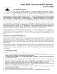
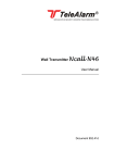
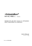
1. Verify DIP switch settings are applicable to the system. The DIP switches (see Figure 1 below) on the electrical
interface board are accessible from the bottom of the cash drawer unit.
2. Connect the cash drawer to the appropriate dedicated RS-232 serial COM port on the host device.
3. Open COM port and wait twelve seconds to charge drawer (first time only) before transmitting the opening sequence.
4. Open the cash drawer through the software, or refer to step 5 below.
5. Transmit a BEL character from the host to open cash drawer. See Section II and Section III for examples.
6. If cash drawer openings occur on power up/down, a higher level of noise immunity should be used. This can be done
by setting DIP switch 9 and switch 10 off, switch 8 on, and send any sequence of characters, such as “UU”, that
produce a minimum of 8 pulse edges. Refer to Chart #1 for more details.
Switch Settings Description
1
off
ON
Diagnostic Tool
* Power Test disabled
Power Test enabled (Do not use until instructed.)
2
ON
off
Extended Security
* RTS Disable set
RTS Disable released (Do not use until instructed.)
4
off
ON
Signal Source
* PC operation enabled (DB9 contact 3, DB25 contact 2)
Terminal operation enabled (DB9 contact 2, DB25 contact3)
5
ON
off
CTS/RTS Handshaking
* handshaking enabled (If ON, do not enable CTS drawer status.)
handshaking disabled (RTS at DB9 contact 7, DB25 contact 4)
6
off
ON
off
7
off
off
ON
Drawer Status
* drawer status disabled
CTS drawer status (DB9 contact 8, DB25 contact 5)
RI drawer status (DB9 contact 9, DB25 contact 22)
9
ON
off
off
10
off
ON
off
Minimum Opening Pulse Edges
* Pulse window set to 2 edges
Pulse window set to 1 edge
Pulse window set to 8 edges
3
ON
off
FIGURE 1
5
off
8
off
off
ON
* The APG default settings are shown as bold text above.
II. Cash Drawer Testing
The following examples will illustrate how to open the drawer with the original factory switch settings. If the operating
system is Windows™ environment, use the DOS window for the command entry. COM1 is used throughout this
example. Replace COM1 with COM2, etc., if appropriate. Type the bold letters into the computer.
NOTE: The interface operates from 600 to 19.2K baud. 9600 baud is shown only as an example. The interface is not
affected by changes in parity, bit length, and stop bits. These parameters can be any setting required by the user.
A. Opening the Cash Drawer using DOS
1. Verify the switches on the cash drawer are set to the original factory settings. Refer to Figure 1 in Section I for these
settings.
2. Set the Mode command, which will define the communication parameters of the serial port.
C:\>MODE COM1:9600,N,8,1 ("Enter" key)
3. Wait twelve (12) seconds before attempting to open the cash drawer the first time. The following command will
transmit the BEL character (Ctrl and G keys held at the same time) to open the cash drawer.
C:\>ECHO ^G>COM1 ("Enter" key)
B. Opening the Cash Drawer using BASIC
To open drawer in Basic:
OPEN "COM1:9600,N,8,1,CS,DS,CD" FOR RANDOM AS #1
REM – MUST REMAIN OPEN IF DRAWER IS POWERED BY DTR/RTS
START = TIMER: WHILE TIMER < START + 12: WEND
REM – 12 SEC FOR 1ST OPENING CHARGING, 6 SEC FOR SUBSEQUENT RECHARGING
PRINT #1, CHR$(7): REM – BEL CHARACTER FOR 2 EDGE PULSE
There are two options for reading drawer status in Basic:
START = TIMER: WHILE TIMER < START + .2: WEND
REM – 200 mSEC ALLOWS DRAWER TO OPEN BEFORE CHECKING STATUS
CODE%=INP(&H3FE): REM – ASSUMING COM1 USED
1) Reading CTS drawer status in Basic (SW5 ON, SW6 off):
IF (CODE% AND 16) = 16 THEN PRINT "–CTS OPTION - DRAWER CLOSED"
IF (CODE% AND 16) = 0 THEN PRINT "–CTS OPTION - DRAWER IS OPEN"
2) Reading RI drawer status in Basic (SW5 off, SW6 ON):
IF (CODE% AND 64) = 64 THEN PRINT "–RI OPTION - DRAWER CLOSED"
IF (CODE% AND 64) = 0 THEN PRINT "–RI OPTION - DRAWER IS OPEN"
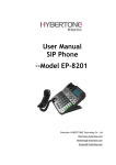
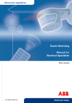
III. Power Supply Installation (Optional)
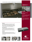
This interface will allow openings as frequently as every 6 seconds
with serial port (COM) power. If a faster cash drawer opening
cycle is required, the external power supply may be installed. Using
the power supply, the drawer can be repeatedly opened every 2-3
seconds. See Figure 2 at right for assembly details.
Board Connector
For Power Supply
LED’s
External Cable
There are situations, such as Windows NT operating systems,
where the power supply is required for proper operation.
IV. Troubleshooting
FIGURE 2
Power Supply
Cable
This section is intended to assist in configuring the SerialPRO II Interface to work with your specific system. The cash
drawer is equipped with two diagnostic lights or LED’s (Light Emitting Diodes) inside the drawer to aid in troubleshooting a system. These lights can be seen by opening the drawer with the key, removing the plastic money tray, and
looking into the back of the cash drawer. The green LED will be off unless the optional power supply is plugged in or
DIP switch 1 is ON. The yellow LED flashes while any data or character(s) is being received.
NOTE: The 484A SerialPRO II interface allows changing of the DIP switch settings with the power and port active.
To observe LED’s with cash drawer closed, place drawer on it’s side and partially extract the interface board and bracket
assembly from the cash drawer by removing the mounting screws. See Figure 2.
A. To Verify Power Is Being Supplied:
If the serial port is used to provide power, turn DIP switch 1 ON. A solid green light indicates power is provided. If the
green LED does not turn on:
1. Check to make sure that the cash drawer is connected to the correct port on the host.
2. Confirm that the port on the host is working properly. Connect another device that has worked previously on this
port, or, if applicable, use Section II or Section III to verify proper operation of port.
CAUTION: Turn DIP switch 1 off after this test. Do not operate the cash drawer with the switch on; it may cause
poor performance of the interface.
If the power supply is providing power and the green LED is not on:
3. Check to make sure that the AC power supply is plugged into a 115 VAC, 60 Hz outlet and verify that the outlet
is functional.
4. Check that the power supply cable is connected properly into the board connector on the circuit board inside the
cash drawer. See Figure 2.
B. To Verify Signal Is Being Received:
A flashing yellow light indicates the interface is receiving data from the serial port. If the yellow LED did not flash:
1. Verify steps 1 and 2 above.
2. Check to make sure that the DIP switches 3 and 4 are set correctly for PC or Terminal operation. Both cannot be
ON or off at the same time.
3. Some software applications require hardware handshaking between the host and peripheral devices. This may
include jumpering the CTS and RTS lines. Check to make sure that DIP switch 5 is ON and switch 6 is off if this
option is required. (Switch 6 enables CTS drawer status and cannot be used with CTS-RTS handshaking
enabled.) Hardware handshaking of DSR, DCD, and DTR is incorporated into the attached interface cable.
4. If the software package checks for the drawer status, verify the correct DIP switch (see table next to Figure 1) is
set ON, and close the drawer to allow the host to transmit the opening data sequence out the serial port.
5. Recheck all the DIP switch settings (if appropriate, reset to default – See Figure 1). Toggle each switch from its
current position to the opposite position and back to be sure each switch is fully seated in the proper position. For
example, if it is ON, turn it off and then ON again.
If the yellow LED flashed, and the drawer did not open:
1. If other devices are on the same port, disconnect them. The Model 484A SerialPRO II Cash Drawer is not
designed to operate with additional devices on the serial port.
2. Make sure that the DIP switch settings (8,9,10) are set less than or equal to the ASCII character(s) pulse count
transmitted by the host. (See Chart #1.)
3. If two or more characters are used to open the cash drawer, check to make sure that the software is sending the
characters sequentially.
4. Configure the drawer to open on one pulse (Switch 8 off, 9 off, 10 ON) to determine if the drawer recognizes any
of the opening commands from the host.
5. If the host device does not provide a high RTS line, change DIP switch 2 to off, and retest the opening code.
Leaving switch 2 off will reduce the noise immunity of the interface.
If difficulties persist, contact your supplier for more information or contact:
APG Cash Drawer technical support at (763) 571-5000, or via email at [email protected]
Windows™ is a trademark of Microsoft Corporation.
The APG logo, APG® Cash Drawer, and SerialPRO® are registered trademarks of APG Cash Drawer.
Copyright 2002 by APG Cash Drawer; Minneapolis, Minnesota; U.S.A.
PN: M-23G-484A Rev. –
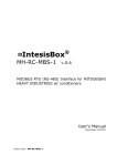
CHART #1 - PULSE EDGES PER ASCII CHARACTER
NON-PRINTABLE ASCII CHARACTERS
Number
ASCII
Control Dec. Hex of Pulse
Character Character Num Num Edges
NUL
<Ctrl><@> 0
0
1
SOH
<Ctrl><A> 1
1
2
STX
<Ctrl><B> 2
2
2
ETX
<Ctrl><C> 3
3
2
EOT
<Ctrl><D> 4
4
2
ENQ
<Ctrl><E> 5
5
3
ACK
<Ctrl><F> 6
6
2
BEL
<Ctrl><G> 7
7
2
BS
<Ctrl><H> 8
8
2
HT
<Ctrl><I> 9
9
3
LF
<Ctrl><J> 10
A
3
VT
<Ctrl><K> 11
B
3
FF
<Ctrl><L> 12
C
2
CR
<Ctrl><M> 13
D
3
SO
<Ctrl><N> 14
E
2
SI
<Ctrl><0> 15
F
2
DLE
DC1
DC2
DC3
DC4
NAK
SYN
ETB
CAN
EM
SUB
ESC
FS
GS
RS
US
<Ctrl><P>
<Ctrl><Q>
<Ctrl><R>
<Ctrl><S>
<Ctrl><T>
<Ctrl><U>
<Ctrl><V>
<Ctrl><W>
<Ctrl><X>
<Ctrl><Y>
<Ctrl><Z>
<Ctrl><[>
<Ctrl></>
<Ctrl><]>
<Ctrl><^>
<Ctrl><->
16
17
18
19
20
21
22
23
24
25
26
27
28
29
30
31
10
11
12
13
14
15
16
17
18
19
1A
1B
1C
1D
1E
1F
2
3
3
3
3
4
3
3
2
3
3
3
2
3
2
2
PRINTABLE ASCII CHARACTERS
Number
ASCII
Dec. Hex of Pulse
ASCII
Character Num Num Edges
Character
space
32 20
2
@
!
33 21
3
A
"
34 22
3
B
#
35 23
3
C
$
36 24
3
D
%
37 25
4
E
&
38 26
3
F
'
39 27
3
G
(
40 28
3
H
)
41 29
4
I
*
42 2A
4
J
+
43 2B
4
K
,
44 2C
3
L
45 2D
4
M
.
46 2E
3
N
/
47 2F
3
O
0
1
2
3
4
5
6
7
8
9
:
;
<
=
>
?
48
49
50
51
52
53
54
55
56
57
58
59
60
61
62
63
30
31
32
33
34
35
36
37
38
39
3A
3B
3C
3D
3E
3F
2
3
3
3
3
4
3
3
2
3
3
3
2
3
2
2
P
Q
R
S
T
U
V
W
X
Y
Z
[
\
]
^
_
Dec.
Num
64
65
66
67
68
69
70
71
72
73
74
75
76
77
78
79
80
81
82
83
84
85
86
87
88
89
90
91
92
93
94
95
Number
Hex of Pulse
Num Edges
40
2
41
3
42
3
43
3
44
3
45
4
46
3
47
3
48
3
49
4
4A
4
4B
4
4C
3
4D
4
4E
3
4F
3
50
51
52
53
54
55
56
57
58
59
5A
5B
5C
5D
5E
5F
3
4
4
4
4
5
4
4
3
4
4
4
3
4
3
3
ASCII
Character
`
a
b
c
d
e
f
g
h
i
j
k
l
m
n
o
p
q
r
s
t
u
v
w
x
y
z
{
|
}
~
DEL
Dec.
Num
96
97
98
99
100
101
102
103
104
105
106
107
108
109
110
111
Number
Hex of Pulse
Num Edges
60
2
61
3
62
3
63
3
64
3
65
4
66
3
67
3
68
3
69
4
6A
4
6B
4
6C
3
6D
4
6E
3
6F
3
112 70
113 71
114 72
115 73
116 74
117 75
118 76
119 77
120 78
121 79
122 7A
123 7B
124 7C
125 7D
126 7E
127 7F
2
3
3
3
3
4
3
3
2
3
3
3
2
3
2
2
NOTE: If serial port is set for 7 bit characters, subtract 1 pulse from ASCII characters "@" (hex 40) to "DEL" (hex 7F).
M-23G-484A Rev -
®
Copyright 2002 APG Cash Drawer