1
Model 212A Smart SerialPRO® Interface
User’s Guide
Functional Description
Your APG cash drawer includes the 212A Smart SerialPRO® Interface that provides a
programmable RS232 serial connection to the RS232 serial port of the host device (computer,
terminal, etc.). The cash drawer will open when it receives an ASCII sequence (1 or 2 characters:
identical or different) that matches the dip switch settings on the bottom of the cash drawer. The
interface requires an external power supply provided by APG. The interface has diagnostic lights to assist in installation
and troubleshooting. Serial port sharing is accomplished using a “Y” connector, an integral part of the APG supplied
cable. This interface is capable of sharing the serial port with other Point of Sale peripheral devices, such as bar code
scanner, serial printer, pole display, or another cash drawer. When properly configured, the cash drawer and other devices
will share the same information transmitted from the serial port but each will respond to that information independently.
The unique design of this interface allows you to select serial port parameters such as baud rates from 300 to 19200,
parity, data bit word length. The number of opening characters (1 or 2), PC or terminal operation, and the ASCII opening
character sequence are also selectable. The DIP switches for these options are conveniently located on the bottom of the
cash drawer unit near the cable exit. Drawer reporting status is configurable with jumpers inside the cash drawer.
Hardware handshaking is also configurable inside the cash drawer with jumpers on the interface board.
The interface includes a “Y” cable for connection to the serial port. As a standard product, this cable is equipped with 25
pin female (DB25F) connectors and a 25 pin male (DB25M) connector. A 25 pin male (DB25M) to 9 pin male (DB9M)
gender changer and a 25 pin male (DB25M) to 9 pin female (DB9F) gender changer are both included with the cash
drawer.
Support for MacIntosh® RS422 Interface
The 212A Smart SerialPRO® Interface can be used with a MacIntosh host device by adding the APG Cash Drawer
MacIntosh cable adapter kit. The part number for the adapter kit is M-16E-0212A-MACKIT and is available from APG
Cash Drawer or your Point Of Sale hardware dealer. This kit consists of a DB25 male to 8 pin mini-DIN male cable
adapter and a DB25 female to 8 pin mini-DIN female cable adapter. Both cables connect to the “Y” cable provided with
the cash drawer.
In order to properly interface to the MacIntosh system, switch #5 on Bank C must be changed to the ON position. Since
the MacIntosh does not follow a transmitted signal with a parity check, changing switch #5 on Bank C to the ON position
will disable any parity check performed by the cash drawer. Follow the remainder of the instructions to finish configuring
the cash drawer.
I. Configuration and Use
This Guide assumes the user has some technical experience connecting computer peripherals.
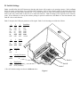
1. Verify DIP switch and jumper settings are applicable to the system. The DIP switches (see Figure 6) on the electrical
interface board are accessible from the bottom of the cash drawer unit.
2. The jumper settings (see Figure 1) are accessible from inside the cash drawer. Remove the till and inner drawer to
access the jumpers if required.
3. Connect the cash drawer to the appropriate dedicated RS-232 serial COM port on the host device with the “Y” cable
using the connector labeled “SERIAL PORT”. If the serial port will be shared, plug the other device into the short
end of the “Y” cable by removing the plastic cap over the DB25 male connector marked “AUX DEVICE”. This
connector is a physical extension of the serial port with all 25 pins corresponding to those on the serial port.
4. Plug the power supply into a suitable 110 VAC power source. Connect the DC plug of the power supply into the jack
located adjacent to the DIP switches on the bottom of the cash drawer.
5. If desired, attach the self-adhesive DIP switch definition sticker to the bottom of the cash drawer, next to the DIP
switch opening for quick reference.
6. Open the cash drawer through the software, or refer to step 7 below.
7. Transmit the opening character(s) from the host to open cash drawer. See Section IIA, B, and C for examples.
II. Cash Drawer Testing
The following examples will illustrate how to open the drawer with the original factory switch settings. If the operating
system is Windows™ environment, use the DOS window for the command entry. COM1 is used throughout this
example. Replace COM1 with COM2, etc., if appropriate. Type the bold letters into the computer.
A. Opening the Cash Drawer using DOS
1. Verify the switches on the cash drawer are set to the original factory settings. Refer to Figure 6 in Section III.B for
these settings.
2. Set the Mode command, which will define the communication parameters of the serial port.
C:\>MODE COM1:9600,O,7,1 ("Enter" key)
3. The following command will transmit all of the files in the directory out to the serial port. If the cash drawer is
connected properly, the yellow indicating light inside the cash drawer will flash as characters are received.
C:\>DIR >COM1 ("Enter" key)
4. The following command will transmit two left bracket characters to open the cash drawer.
C:\>ECHO [[>COM1 ("Enter" key)
At this point, the cash drawer should open with the original factory dip switch setting.
B. Opening the Cash Drawer using BASIC
To open drawer in Basic:
OPEN "COM1:9600,O,7,1,CS,DS,CD" FOR RANDOM AS #1
PRINT #1, "[[": REM – TWO LEFT BRACKET CHARACTERS
There are two options for reading drawer status in Basic:
START = TIMER: WHILE TIMER < START + .2: WEND
REM – 200 mSEC ALLOWS DRAWER TO OPEN BEFORE CHECKING STATUS
CODE%=INP(&H3FE): REM – ASSUMING COM1 USED
1) Reading CTS drawer status in Basic (See Figure 4):
IF (CODE% AND 16) = 16 THEN PRINT "–CTS OPTION - DRAWER CLOSED"
IF (CODE% AND 16) = 0 THEN PRINT "–CTS OPTION - DRAWER IS OPEN"
2) Reading RI drawer status in Basic (See Figure 5):
IF (CODE% AND 64) = 64 THEN PRINT "–RI OPTION - DRAWER CLOSED"
IF (CODE% AND 64) = 0 THEN PRINT "–RI OPTION - DRAWER IS OPEN"
C. Opening the Cash Drawer using Visual Basic
Install the Microsoft COM control into the Components bar. Add MSCOMM to the form and the following into the code
as applicable.
MSComm1.CommPort = 1
MSComm1.PortOpen = True
MSComm1.RTSEnable = True
MSComm1.DTREnable = True
...
MSComm1.Output = “[[“
...
If MSComm1.CTSHolding Then
...
‘
‘
‘
‘
Define COM1 as port to be opened
Open the serial port
Turn RTS high
Turn DTR high
‘ Transmit characters to open cash drawer
‘ Cash drawer is closed if CTS status enabled
Note that RI for cash drawer status is not adequately supported in Visual Basic. OPOS drivers (which support both
methods for drawer status, RI & CTS) are available for developers from the APG website: http://www.apgcd.com.
III. Jumper and Switch Setup
The 212A Smart SerialPRO® Interface does not require hardware handshaking for proper operation. Any hardware
handshaking that the host requires for peripheral devices is accomplished directly on the interface board with pin jumpers,
which can be reconfigured for specific requirements. The cash drawer comes equipped with a drawer status switch, which
can be used to signal the host whether the drawer is opened or closed. Pin jumpers on the interface board select the serial
port status line that reports drawer status. Three (3) sets of DIP switches are located on the bottom of the cash drawer,
next to the connector for the interface cable. These switches configure the opening characters and the serial port
operation. It is not necessary to remove power when changing the dip switch settings.
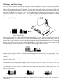
A. Jumper Settings
Figure 1
Factory Default Setting
Jumper block J1 configures the DSR-DTR-DCD hardware handshaking. The cash drawer is configured at the factory for
full DTR handshaking. In special circumstances where hardware handshaking is not needed or desired, the appropriate
jumpers can be removed from the interface board. When sharing the same serial port with other devices, we recommend
that one of the other devices controls hardware handshaking and the jumpers on the interface should be removed.
Remove the left jumper on J1 to disconnect DSR-DTR handshaking. Remove the right jumper on J1 to disconnect DTRDCD handshaking. Remove all jumpers on J1 to disable DTR handshaking as shown in Figure 2.
Figure 2
Jumper block J2 configures the RTS-CTS hardware handshaking and allows for reporting of cash drawer status. Unless
otherwise specified, the drawer is configured with the status switch disabled at the factory, and RTS-CTS handshaking
enabled.
To disable the Return To Send (RTS) and Clear To Send hardware handshaking, remove the jumper over the right two
pins, as shown in Figure 3.
The cash drawer can be configured to report the opened/closed status on the Clear To Send (CTS) line, pin 5 on a 25 pin
port, as shown in Figure 4. Note that RTS-CTS handshaking will be disabled.
The cash drawer can be configured to report the opened/closed status on the Ring Indicator (RI) line, pin 22 on a 25 pin
port, as shown in Figure 5.
Figure 3
Figure 4
Figure 5
When the cash drawer is closed, the switch status line is electrically high, and when the drawer is open, the status line is
electrically low.
B. Switch Settings
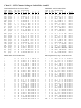
Banks A and B define the ASCII character(s) that the cash drawer will recognize as its opening sequence. Refer to Chart
#1 for the proper switch settings for a particular ASCII character. Refer to the software supplier to determine the ASCII
sequence used as the cash drawer opening code. If one ASCII character is sent by the software package to open the cash
drawer, then only switch bank A must be set to match this character. Bank B settings will be ignored in one character
mode. If two characters are sent by the software package to open the cash drawer, then Bank A is the first character, and
Bank B is the second character.
Bank C interprets the COM port parameters of the signal. Bank C switch settings are defined as follows:
1
OFF
on
OFF
on
OFF
on
OFF
2
on
OFF
OFF
on
on
OFF
OFF
3
on
on
on
OFF
OFF
OFF
OFF
Baud Rate
300
600
1200
2400
4800
9600
19,200
4
OFF
on
OFF
5
on
OFF
OFF
Parity
None
Even
Odd
6
on
OFF
Data Bits
7
8
7
on
OFF
Opening Characters
1
2
8_
on
OFF
Host Device
DCE (Computer)
DTE (Terminal)
Bank A
Bank B
Bank C
* The APG default settings are shown as bold text above.
Figure 6
Chart #1 – ASCII Character Settings for Switch Banks A and B
NON-PRINTABLE ASCII CHARACTERS
PRINTABLE ASCII CHARACTERS
ASCII
Char.
NUL
SOH
STX
ETX
EOT
ENQ
ACK
BEL
BS
HT
LF
VT
FF
CR
SO
SI
Control
Character
[Ctrl] @
[Ctrl] A
[Ctrl] B
[Ctrl] C
[Ctrl] D
[Ctrl] E
[Ctrl] F
[Ctrl] G
[Ctrl] H
[Ctrl] I
[Ctrl] J
[Ctrl] K
[Ctrl] L
[Ctrl] M
[Ctrl] N
[Ctrl] O
Dec.
Num
0
1
2
3
4
5
6
7
8
9
10
11
12
13
14
15
Hex
Num
0
1
2
3
4
5
6
7
8
9
A
B
C
D
E
F
DIP Switch Setting
1
2
3
4
on on on on
OFF on on on
on OFF on on
OFF OFF on on
on on OFF on
OFF on OFF on
on OFF OFF on
OFF OFF OFF on
on on on OFF
OFF on on OFF
on OFF on OFF
OFF OFF on OFF
on on OFF OFF
OFF on OFF OFF
on OFF OFF OFF
OFF OFF OFF OFF
5
on
on
on
on
on
on
on
on
on
on
on
on
on
on
on
on
6
on
on
on
on
on
on
on
on
on
on
on
on
on
on
on
on
7
on
on
on
on
on
on
on
on
on
on
on
on
on
on
on
on
8
on
on
on
on
on
on
on
on
on
on
on
on
on
on
on
on
ASCII
Char.
@
A
B
C
D
E
F
G
H
I
J
K
L
M
N
O
Dec.
Num
64
65
66
67
68
69
70
71
72
73
74
75
76
77
78
79
Hex
Num
40
41
42
43
44
45
46
47
48
49
4A
4B
4C
4D
4E
4F
DIP Switch Setting
1
2
3
4
on on on on
OFF on on on
on OFF on on
OFF OFF on on
on on OFF on
OFF on OFF on
on OFF OFF on
OFF OFF OFF on
on on on OFF
OFF on on OFF
on OFF on OFF
OFF OFF on OFF
on on OFF OFF
OFF on OFF OFF
on OFF OFF OFF
OFF OFF OFF OFF
DLE
DC1
DC2
DC3
DC4
NAK
SYN
ETB
CAN
EM
SUB
ESC
FS
GS
RS
US
[Ctrl]
[Ctrl]
[Ctrl]
[Ctrl]
[Ctrl]
[Ctrl]
[Ctrl]
[Ctrl]
[Ctrl]
[Ctrl]
[Ctrl]
[Ctrl]
[Ctrl]
[Ctrl]
[Ctrl]
[Ctrl]
16
17
18
19
20
21
22
23
24
25
26
27
28
29
30
31
10
11
12
13
14
15
16
17
18
19
1A
1B
1C
1D
1E
1F
on
OFF
on
OFF
on
OFF
on
OFF
on
OFF
on
OFF
on
OFF
on
OFF
OFF
OFF
OFF
OFF
OFF
OFF
OFF
OFF
OFF
OFF
OFF
OFF
OFF
OFF
OFF
OFF
on
on
on
on
on
on
on
on
on
on
on
on
on
on
on
on
on
on
on
on
on
on
on
on
on
on
on
on
on
on
on
on
on
on
on
on
on
on
on
on
on
on
on
on
on
on
on
on
P
Q
R
S
T
U
V
W
X
Y
Z
[
\
]
^
_
80
81
82
83
84
85
86
87
88
89
90
91
92
93
94
95
50
51
52
53
54
55
56
57
58
59
5A
5B
5C
5D
5E
5F
on on on
OFF on on
on OFF on
OFF OFF on
on on OFF
OFF on OFF
on OFF OFF
OFF OFF OFF
on on on
OFF on on
on OFF on
OFF OFF on
on on OFF
OFF on OFF
on OFF OFF
OFF OFF OFF
P
Q
R
S
T
U
V
W
X
Y
Z
[
/
]
^
-
on
on
OFF
OFF
on
on
OFF
OFF
on
on
OFF
OFF
on
on
OFF
OFF
on
on
on
on
OFF
OFF
OFF
OFF
on
on
on
on
OFF
OFF
OFF
OFF
on
on
on
on
on
on
on
on
OFF
OFF
OFF
OFF
OFF
OFF
OFF
OFF
PRINTABLE ASCII CHARACTERS
5
on
on
on
on
on
on
on
on
on
on
on
on
on
on
on
on
6
on
on
on
on
on
on
on
on
on
on
on
on
on
on
on
on
on OFF on
on OFF on
on OFF on
on OFF on
on OFF on
on OFF on
on OFF on
on OFF on
OFF OFF on
OFF OFF on
OFF OFF on
OFF OFF on
OFF OFF on
OFF OFF on
OFF OFF on
OFF OFF on
7
OFF
OFF
OFF
OFF
OFF
OFF
OFF
OFF
OFF
OFF
OFF
OFF
OFF
OFF
OFF
OFF
8
on
on
on
on
on
on
on
on
on
on
on
on
on
on
on
on
OFF on
OFF on
OFF on
OFF on
OFF on
OFF on
OFF on
OFF on
OFF on
OFF on
OFF on
OFF on
OFF on
OFF on
OFF on
OFF on
BOLD – Original Factory Settings = ASCII Character #91
Space
!
"
#
$
%
&
'
(
)
*
+
,
.
/
32
33
34
35
36
37
38
39
40
41
42
43
44
45
46
47
20
21
22
23
24
25
26
27
28
29
2A
2B
2C
2D
2E
2F
on
OFF
on
OFF
on
OFF
on
OFF
on
OFF
on
OFF
on
OFF
on
OFF
on
on
OFF
OFF
on
on
OFF
OFF
on
on
OFF
OFF
on
on
OFF
OFF
on
on
on
on
OFF
OFF
OFF
OFF
on
on
on
on
OFF
OFF
OFF
OFF
on
on
on
on
on
on
on
on
OFF
OFF
OFF
OFF
OFF
OFF
OFF
OFF
on
on
on
on
on
on
on
on
on
on
on
on
on
on
on
on
OFF
OFF
OFF
OFF
OFF
OFF
OFF
OFF
OFF
OFF
OFF
OFF
OFF
OFF
OFF
OFF
on
on
on
on
on
on
on
on
on
on
on
on
on
on
on
on
on
on
on
on
on
on
on
on
on
on
on
on
on
on
on
on
`
a
b
c
d
e
f
g
h
i
j
k
l
m
n
o
96
97
98
99
100
101
102
103
104
105
106
107
108
109
110
111
60
61
62
63
64
65
66
67
68
69
6A
6B
6C
6D
6E
6F
on
OFF
on
OFF
on
OFF
on
OFF
on
OFF
on
OFF
on
OFF
on
OFF
on
on
OFF
OFF
on
on
OFF
OFF
on
on
OFF
OFF
on
on
OFF
OFF
on
on
on
on
OFF
OFF
OFF
OFF
on
on
on
on
OFF
OFF
OFF
OFF
on
on
on
on
on
on
on
on
OFF
OFF
OFF
OFF
OFF
OFF
OFF
OFF
on
on
on
on
on
on
on
on
on
on
on
on
on
on
on
on
OFF
OFF
OFF
OFF
OFF
OFF
OFF
OFF
OFF
OFF
OFF
OFF
OFF
OFF
OFF
OFF
OFF
OFF
OFF
OFF
OFF
OFF
OFF
OFF
OFF
OFF
OFF
OFF
OFF
OFF
OFF
OFF
on
on
on
on
on
on
on
on
on
on
on
on
on
on
on
on
0
1
2
3
4
5
6
7
8
9
:
;
<
=
>
?
48
49
50
51
52
53
54
55
56
57
58
59
60
61
62
63
30
31
32
33
34
35
36
37
38
39
3A
3B
3C
3D
3E
3F
on
OFF
on
OFF
on
OFF
on
OFF
on
OFF
on
OFF
on
OFF
on
OFF
on
on
OFF
OFF
on
on
OFF
OFF
on
on
OFF
OFF
on
on
OFF
OFF
on
on
on
on
OFF
OFF
OFF
OFF
on
on
on
on
OFF
OFF
OFF
OFF
on
on
on
on
on
on
on
on
OFF
OFF
OFF
OFF
OFF
OFF
OFF
OFF
OFF
OFF
OFF
OFF
OFF
OFF
OFF
OFF
OFF
OFF
OFF
OFF
OFF
OFF
OFF
OFF
OFF
OFF
OFF
OFF
OFF
OFF
OFF
OFF
OFF
OFF
OFF
OFF
OFF
OFF
OFF
OFF
on
on
on
on
on
on
on
on
on
on
on
on
on
on
on
on
on
on
on
on
on
on
on
on
on
on
on
on
on
on
on
on
p
q
r
s
t
u
v
w
x
y
z
{
|
}
~
DEL
112
113
114
115
116
117
118
119
120
121
122
123
124
125
126
127
70
71
72
73
74
75
76
77
78
79
7A
7B
7C
7D
7E
7F
on
OFF
on
OFF
on
OFF
on
OFF
on
OFF
on
OFF
on
OFF
on
OFF
on
on
OFF
OFF
on
on
OFF
OFF
on
on
OFF
OFF
on
on
OFF
OFF
on
on
on
on
OFF
OFF
OFF
OFF
on
on
on
on
OFF
OFF
OFF
OFF
on
on
on
on
on
on
on
on
OFF
OFF
OFF
OFF
OFF
OFF
OFF
OFF
OFF
OFF
OFF
OFF
OFF
OFF
OFF
OFF
OFF
OFF
OFF
OFF
OFF
OFF
OFF
OFF
OFF
OFF
OFF
OFF
OFF
OFF
OFF
OFF
OFF
OFF
OFF
OFF
OFF
OFF
OFF
OFF
OFF
OFF
OFF
OFF
OFF
OFF
OFF
OFF
OFF
OFF
OFF
OFF
OFF
OFF
OFF
OFF
on
on
on
on
on
on
on
on
on
on
on
on
on
on
on
on
IV. Troubleshooting
This section is intended to assist in configuring the 212A Smart SerialPRO Interface to work with your specific system.
The cash drawer is equipped with three diagnostic lights or LED’s (Light Emitting Diodes) inside the drawer to aid in
trouble-shooting a system. These lights can be seen by opening the drawer with the key, removing the plastic money tray,
and looking into the back of the cash drawer.
1. A Flashing Green LED indicates healthy operation of the supporting electronics inside the cash drawer. It will
flash at approximately 1/2 second intervals when the drawer is powered and the electronics are functioning
properly.
2. A Flashing Yellow LED indicates that ASCII characters are being received. NOTE: This light does not
necessarily indicate that the proper opening sequence has been received. This light only provides an indication
that ASCII characters are being transmitted by the host and that the cash drawer is connected properly.
3. A Flashing Red LED indicates that a parity or framing error has occurred between the cash drawer and the host.
Most likely, there are incorrect communication settings (i.e. baud rate, parity, or word length) between the host
and the cash drawer.
A. If the green LED is not flashing,
1. Check to make sure that the power adapter is plugged into a 110VAC, 60Hz outlet and that the outlet is
functional.
2. Check to make sure that the DC adapter cable is connected to the cash drawer. The connector is located next to
the serial cable connector on the bottom of the cash drawer.
B. If the red LED is on or flashing,
1. Check to make sure that the baud rate, word length, and parity DIP switches match the setting the host device is
sending. This LED is illuminated normally when one of these parameters is not set properly.
2. Check to make sure that the cash drawer is connected to the correct serial port.
3. Note that the red light will continue to flash until the interface receives the correct signal, or until power is
removed from the cash drawer.
C. If the yellow LED does not flash when characters are transmitted from the port,
1. Check to make sure that switch 8 of Bank C (the DCE/DTE switch) is in the correct position.
2. Check to make sure that the cash drawer is connected to the correct serial port on the host.
3. Check to make sure that the cable is connected properly and none of the pins are damaged.
4. Confirm that the port on the host is working properly. Connect another device that has worked previously on this
port.
5. If applicable, use the DOS level example illustrated in the “Cash Drawer Testing” section to verify proper
operation of the port.
6. Recheck all of the DIP switch settings. Toggle each switch from its current position to the opposite position and
back to be sure each switch is fully seated in the proper position. For example, if it is on, turn it off and then on
again. Do this for all of the DIP switches.
7. If the software package checks for the drawer status, and if the switch in the cash drawer is enabled, make sure the
drawer is closed to allow the host to transmit the opening character sequence out the serial port.
D. Some software applications require hardware handshaking between the host and peripheral devices. This may include
a jumper between the Clear To Send (CTS) line to the Request To Send (RTS) line, or jumpers between the Data
Terminal Ready (DTR) line to the Data Set Ready (DSR) or Data Carrier Detect (DCD) lines.
1. Check the jumpers on the interface board to be sure that they are present and fully seated. (See Figure 1.)
2. If sharing the serial port with other devices, the other devices may perform hardware handshaking. Remove the
jumpers from the interface. (See Figure 2.)
E. If the cash drawer still does not open,
1. Make sure that the DIP switch settings on the cash drawer match the ASCII character(s) transmitted by the host
device and they are in the correct order. If two characters are used to open the cash drawer, check to make sure
that the software package is sending the two characters in immediate succession and in order with no other ASCII
characters in between. NOTE: After the cash drawer has received an opening signal from the host device, the
circuit board will ignore any more transmitted data for a four (4) second interval to prevent rapid, repetitive
opening cycles.
2. Check to make sure that the software package is telling the cash drawer to open. The software may require the
user to configure the opening character sequence during the setup process.
3. If other devices are on the same port, disconnect them and test the cash drawer alone. Be sure to set the jumpers
on the interface board back to factory default.
4. On very high speed serial ports in Windows operating systems, the Advanced Port Settings may have to be set at a
lower rate. Enter the COM port properties window and reduce the Transmit Buffer to a lower setting.
a. Press the “Start” button and select Control Panel then select System Properties. – OR – Right click on “My
Computer” icon and select Properties.
b. Change to Device Manager tab and select “Communications Port COMx”, where “x” is the port number used,
then select “Properties”.
c. Change to Port Settings tab and select “Advanced…”.
d. Reduce the Transmit Buffer slider bar one or two notches.
5. Configure the drawer to open on only one character to determine if the drawer recognizes any of the opening
characters sent from the host.
If difficulties persist, contact your supplier for more information or contact:
APG Cash Drawer technical support at (763) 571-5000, or via email at [email protected]
FCC Warning
This equipment generates, uses and can radiate radio frequency energy and if not installed and used in accordance with
the instruction manual, may cause interference to radio communications. It has been tested and found to comply with
limits for a Class A computing device pursuant to SubPart J of Part 15 of FCC rules, which are designed to provide
reasonable protection against such interference when operated in a commercial environment. Operation of this equipment
in a residential area is likely to cause interference in which case the user at their own expense will be required to take
whatever measures may be required to correct the interference.
If this equipment does cause interference to radio or television reception, which can be determined by turning the
equipment off and on, the user is encouraged to try to correct the interference by one or more of the following measures:
1. Reorient the receiving antenna.
2. Relocate the equipment with respect to the receiver.
3. Plug the equipment into a different outlet so that the computing device and receiver are on different branch circuits.
If necessary, the user should consult the dealer or an experienced radio/television technician for additional suggestions.
The user may find the following booklet prepared by the Federal Communications Commission helpful:
“How to Identify and Resolve Radio-TV Interference Problems”. This booklet is available from the U.S. Government
Printing Office, Washington, DC 20402. Order Stock No. 004-000-00345-4.
MacIntosh® is a registered trademark of Apple Computer Corp.
Windows™ is a trademark of Microsoft Corporation.
The APG logo, APG® Cash Drawer, and SerialPRO® are registered trademarks of APG Cash Drawer.
Copyright 2001 by APG Cash Drawer; Minneapolis, Minnesota; U.S.A.
PN: M-23G-212A Rev. A