1
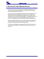
kcSerial User Guide
version 2006.FEB.20
kcSerial User Guide
version 2006.FEB.20
TABLE OF CONTENTS
1
Preface ......................................................................................................................................4
1.1
1.2
1.3
2
Purpose..........................................................................................................................................4
Definitions and Acronyms ..............................................................................................................4
Feedback .......................................................................................................................................5
Overview....................................................................................................................................6
2.1
2.2
Modes of Operation........................................................................................................................6
System Configuration.....................................................................................................................6
2.2.1
2.2.2
2.3
2.4
3
4
Successful Connection.................................................................................................................13
Unsuccessful Connection.............................................................................................................13
Disconnect with Remote Device..............................................................................................15
6.1
6.2
6.3
7
Master device configuration .........................................................................................................10
Slave device configuration ...........................................................................................................11
kcSerial interface-to-Host Baud Rate ...........................................................................................11
Connect with Remote Device ..................................................................................................13
5.1
5.2
6
System Data Flow ..........................................................................................................................7
Commands and Responses ...........................................................................................................8
Startup .......................................................................................................................................9
Configuration ...........................................................................................................................10
4.1
4.2
4.3
5
Hardware ..............................................................................................................................................6
Software ...............................................................................................................................................7
Disconnect Notification Disabled..................................................................................................16
Disconnect Notification Enabled...................................................................................................17
Both Devices in Command Mode.................................................................................................18
Escape from Bypass Mode .....................................................................................................19
7.1
Connection Still Active .................................................................................................................19
8 Device Discovery.....................................................................................................................20
9 Bonding and Security ..............................................................................................................22
10 Smart Cable.............................................................................................................................24
10.1 Configuration Parameters ............................................................................................................24
10.2 Usage...........................................................................................................................................24
11 Remote Command Mode ........................................................................................................26
11.1 Usage...........................................................................................................................................26
11.2 State Transition Matrix and Diagram............................................................................................26
12 Streaming Serial Mode............................................................................................................28
13 Power Saving Mode ................................................................................................................29
13.1 Deep Sleep Mode ........................................................................................................................29
13.1.1
13.1.2
13.1.3
UART Usage With Deep Sleep ..........................................................................................................29
Deep Sleep Blocking ..........................................................................................................................29
Streaming Serial With Deep Sleep.....................................................................................................29
13.2 Sniff..............................................................................................................................................29
13.3 Auto Sniff Mode............................................................................................................................30
14 GPIO Usage ............................................................................................................................31
14.1 kcSerial Application GPIO PIN Assignments ...............................................................................31
14.2 GPIO AT Commands ...................................................................................................................31
15 Feature Compatibility Matrix....................................................................................................32
© 2006 KC Wirefree
www.kcwirefree.com
Page 2 of 32
kcSerial User Guide
version 2006.FEB.20
LIST OF FIGURES
Figure 1. Physical Connection between Host Platform and Wirefree Serial Interface................................................ 7
Figure 2. Data Flow between kcSerial, Host, and Remote Bluetooth Device............................................................. 8
Figure 3. Event Strings Sent on Startup..................................................................................................................... 9
Figure 4. Command and Event Strings for Master Device Configuration................................................................. 10
Figure 5. Command and Event Strings for Slave Device Configuration................................................................... 11
Figure 6. Command and Event Strings for Baud Rate Configuration....................................................................... 12
Figure 7. Command and Event Strings for Successful Connection.......................................................................... 13
Figure 8. Command and Event Strings for Unsuccessful Connection...................................................................... 14
Figure 9. Escape, Command, and Event Strings for Notification Disabled .............................................................. 16
Figure 10. Escape, Command, and Event Strings for Notification Enabled ............................................................. 17
Figure 11. Escape, Command, and Event Strings for Command Mode................................................................... 18
Figure 12. Escape Sequence and Event String when Connection Is Active ............................................................ 19
Figure 13. Commands and Events for Device Discovery......................................................................................... 21
Figure 14. Command and Event Strings for Successful Bonding............................................................................. 23
Figure 15. Remote Command State Diagram .......................................................................................................... 27
Figure 16. Feature Compatibility Matrix ................................................................................................................... 32
© 2006 KC Wirefree
www.kcwirefree.com
Page 3 of 32
kcSerial User Guide
version 2006.FEB.20
1 Preface
The document describes an embedded application that provides a wirefree
serial cable replacement service using the Bluetooth Serial Port Profile,
kcSerial. Formally, this software was developed by Zeevo Inc. and was
called Zerial.
1.1 Purpose
This document provides guidelines for users of host applications that use the
kcSerial interface. Such host applications may execute on a personal
computer or other device that will primarily pass a serial data stream to the
kcSerial interface, which will then be transferred using either the Bluetooth
Serial Port Profile (SPP) or Dial Up Network Profile (DUN).
The kcSerial interface supports AT-like attention commands for configuration.
The kcSerial User Guide explains the commands and sequences needed to
use the kcSerial interface as a serial port.
For a more detailed discussion on each command, please refer to the
kcSerial Reference Guide.
This document will not explain how to construct an embedded application on
KC Wirefree module, nor explain the implementation details of the kcSerial
interface.
1.2 Definitions and Acronyms
The following acronyms are used in this document.
Table 1. Definitions and Acronyms
Term
Description/Meaning
AT
Text based command standard commonly used for modems
BD
Bluetooth Device
bps
Bits Per Second
CTS
Clear to Send line (hardware flow control input on UART that
allows data transmission)
RTS
Request to Send line (hardware flow control output on UART
that stops receiving data)
RxD
Receive Data line (on UART)
SPP
Serial Port Profile
TxD
Transmit Data line (on UART)
UART
Universal Asynchronous Receiver-Transmitter
© 2006 KC Wirefree
www.kcwirefree.com
Page 4 of 32
kcSerial User Guide
version 2006.FEB.20
1.3 Feedback
We are constantly improving our product and would very much like to get
your feedback. Please send your feedback in an email to
[email protected].
For the latest updates and additional information please visit the KC Wirefree
website at: www.kcwirefree.com
© 2006 KC Wirefree
www.kcwirefree.com
Page 5 of 32
kcSerial User Guide
version 2006.FEB.20
2 Overview
2.1 Modes of Operation
The software behavior of the kcSerial interface is similar to a Hayescompatible modem. The application has two modes, a command mode and a
bypass mode. In the command mode, the host can issue specially formatted
text strings called commands. These command strings can be used for
configuration or to manage a connection with a remote device. Note that the
kcSerial interface does not support the standard Hayes AT command set.
Instead, it has commands that leverage off the vendor-specific command
form.
Once a connection is established, the application transitions to the bypass
mode. In the bypass mode, bytes sent from the host will be sent over the
Bluetooth link to the remote device. Any data received from the remote
device will be delivered to the host.
All bytes received on the UART by the host are transferred to the remote
device with the exception of the Escape sequence. While in the bypass
mode, the kcSerial interface will search for this Escape sequence from the
host. If this sequence is found, the application will go back to command
mode. This allows commands to be issued again from the host, but the
connection to the remote device will remain. Any data received on the
Bluetooth link will be discarded while in command mode.
While in the command mode, the kcSerial interface will send responses back
to the host for commands received. Responses from the kcSerial interface
will also be sent on system reset. These responses are also referred to as
Event strings in this document. Event strings are not sent to the host during
bypass mode. However, it is possible to configure a disconnect notification to
be sent during bypass mode. Please refer to the kcSerial Reference Guide
for more details.
2.2 System Configuration
2.2.1
Hardware
To connect the host to the kcSerial interface, an RS-232 port is used with a
NULL-modem cable. This cable will provide the connections illustrated
below. The default port speed of the application is 115200 bps, with 8 data
bits, no parity, and 1 stop bit. The supported serial port speeds are 9600 bps,
19200 bps, 38400 bps, 57600 bps, 115200 bps, 230400 bps, 460800 bps,
and 921600 bps. Hardware flow control (RTS/CTS) is used by the kcSerial
interface. If CTS is de-asserted, the application will stop its transmission
within one byte. When the kcSerial interface de-asserts RTS, by default it
© 2006 KC Wirefree
www.kcwirefree.com
Page 6 of 32
kcSerial User Guide
version 2006.FEB.20
can accept up to 22 more bytes (i.e., the host is expected to stop transmitting
within 22 bytes).
TxD
TxD
RxD
RxD
Zerial Interface
(TC4002)
Host Platform
RTS
RTS
CTS
CTS
Figure 1. Physical Connection between Host Platform and Wirefree Serial Interface
2.2.2
Software
The kcSerial interface executes on the device connected physically to the
local host. The remote device must at minimum be a device that supports the
Serial Port Profile (SPP) or Dial Up Network Profile (DUN).
If deep sleep is enabled, RTS will be de-asserted (CTS on the local host
side) while the Bluetooth radio is in deep sleep. In order for the application to
accept data or commands again, the local host must pulse its RTS line.
Within 35ms of the pulse, the firmware will accept commands again.
2.3 System Data Flow
The following diagram shows how the data stream into and out of the
kcSerial interface is a part of an overall system that uses the Bluetooth SPP.
The bytes into and out of the application are of two types. The first is for
commands and responses. Commands and responses are handled only
while the application is in command mode. When in bypass mode, the
second type of data stream is transferred directly to/from the UART and the
Bluetooth SPP.
© 2006 KC Wirefree
www.kcwirefree.com
Page 7 of 32
kcSerial User Guide
version 2006.FEB.20
Host
cmd, response,
data stream
UART Control
data
stream
(pass thru)
cm
d
response
control
Bluetooth stacks
and profiles
Comman
d parser
status
Zerial
Bluetooth data
stream
Remote Bluetooth Device
serial data
stream
Remote Host
Figure 2. Data Flow between kcSerial, Host, and Remote Bluetooth Device
2.4 Commands and Responses
A summary of all commands and responses can be found in the kcSerial
Reference Guide.
© 2006 KC Wirefree
www.kcwirefree.com
Page 8 of 32
kcSerial User Guide
version 2006.FEB.20
3 Startup
Upon initialization (due to power up or system reset), the kcSerial interface
starts in command mode and the serial port speed is set to its default baud
rate. The application will then send two event strings (if host event strings are
enabled). One notifies the host that the kcSerial interface is in command
mode and the other lists the BD address of the local device.
Host
Host
Zerial Interface
Zerial Interface
Initialization
Command Mode
AT-ZV -CommandMode-
AT-ZV BDAddress 00043e000000
Figure 3. Event Strings Sent on Startup
Then, the application listens for a connection on the SPP profile and remains
in command mode until a connection is established.
© 2006 KC Wirefree
www.kcwirefree.com
Page 9 of 32
kcSerial User Guide
version 2006.FEB.20
4 Configuration
The configuration of the kcSerial interface allows the user to tailor the
interface for a specific environment. This chapter addresses configuration
through the use of AT commands; please refer to the kcSerial Reference
Guide for a description of these commands.
Configurations may be applied following system startup of the kcSerial
interface. The following subsections will describe common ways of using the
configuration in different situations.
4.1 Master device configuration
If the kcSerial interface is being used as a master device, e.g., used to
initiate connections, a common startup configuration may consist of setting
the security mode.
Host
Zerial
No security
AT+ZV Security Link
Link security
AT-ZV SecurityOk
Figure 4. Command and Event Strings for Master Device Configuration
© 2006 KC Wirefree
www.kcwirefree.com
Page 10 of 32
kcSerial User Guide
version 2006.FEB.20
4.2 Slave device configuration
If the kcSerial interface is being used as a slave device, e.g., used to accept
remote connections, a common startup configuration may consist of setting
the local name and/or the security mode.
Host
Zerial
No security
AT+ZV Security Link
Link security en abled
AT-ZV SecurityOk
Default name
AT+ZV LocalName Zeevo Adapter
Local device name changed to Zeevo Adapter
AT-ZV LocalNameOk
Figure 5. Command and Event Strings for Slave Device Configuration
4.3 kcSerial interface-to-Host Baud Rate
The host and kcSerial interface can communicate at a number of baud rates.
It may be necessary for the host to temporarily change the baud rate from
the baud rate used at power up (the default Dynamic Configuration is 115200
bps). The host can change the baud rate by changing the serial port speed
while in command mode. The new port speed becomes effective once the
response string has been transmitted to the host. This baud rate change
remains in effect until the next system reset or power down. Alternatively, a
new default baud rate may be configured, which will take effect after the next
system reset. The configured baud rate does not directly affect the transfer of
data over the Bluetooth connection.
The possible baud rates are:
•
•
•
•
•
•
9600 bps
19200 bps
38400 bps
57600 bps
115200 bps
230400 bps
© 2006 KC Wirefree
www.kcwirefree.com
Page 11 of 32
kcSerial User Guide
•
•
version 2006.FEB.20
460800 bps
921600 bps
Host
Host
Zerial Interface
Zerial Interface
115200 bps
AT+ZV ChangeBaud 460800
AT-ZV Baudrate Changed
460800 bps
Figure 6. Command and Event Strings for Baud Rate Configuration
© 2006 KC Wirefree
www.kcwirefree.com
Page 12 of 32
kcSerial User Guide
version 2006.FEB.20
5 Connect with Remote Device
In order to create a connection with a remote device, the host issues a
command string to the kcSerial interface. This connection command may
only be sent while in the command mode and when there is no active
connection. The BD address of the remote device must be known at the time
the connection is requested. Once the connection is established, the
application goes into bypass mode.
5.1 Successful Connection
If the connection request is successful, the application will go to the bypass
mode. The response can take a few seconds.
Zerial A
Zerial A
(master)
(master)
Host A
Host A
Zerial B
Zerial B
(slave)
(slave)
Host B
Host B
Setup
Setup
Command Mode-Not Connected
Command Mode-Not Connected
AT+ZV SPPConnect
BDAddrB
SPP Connection Established
Bypass Mode - Connected
Bypass Mode - Connected
AT-ZV ConnectionUp
AT-ZV ConnectionUp
AT-ZV -BypassMode
AT-ZV -BypassMode
Figure 7. Command and Event Strings for Successful Connection
5.2 Unsuccessful Connection
There are numerous reasons a connection may not be established including
remote device rejection due to security or poor RF quality. If the connection
request is not successful, the application will remain in command mode. A
response can take a few seconds.
© 2006 KC Wirefree
www.kcwirefree.com
Page 13 of 32
kcSerial User Guide
Zerial A
(master)
Host A
version 2006.FEB.20
Zerial B
(slave)
Host B
Setup
Setup
Command Mode - Not
Connected
AT+ZV SPPConnect
BDAddrB
Command Mode - Not
Connected
SPP Connection Failed
AT-ZV
SPPConnectionClosed
Figure 8. Command and Event Strings for Unsuccessful Connection
© 2006 KC Wirefree
www.kcwirefree.com
Page 14 of 32
kcSerial User Guide
version 2006.FEB.20
6 Disconnect with Remote Device
Once a connection is made, either device may request a disconnect. Also, a
disconnect may occur unexpectedly due to changing conditions such as
moving a device beyond the reception range. This section will illustrate
disconnects under different situations.
In order to terminate an existing connection with a remote device, the host
issues a disconnect command string. However, once a connection to a
remote device has been established, the application is in bypass mode.
Therefore, the host must first put the application in command mode before it
can close the connection. The Escape sequence is sent to begin this
process. The Escape sequence is discussed in greater detail in Section 7.
Once the kcSerial interface is back in command mode, the host sends the
Disconnect command string. The application notifies the host when the
connection is broken and returns to command mode.
For disconnects initiated due to changing RF conditions, both hosts would
receive the same notification as the non-initiating host in the following
examples.
© 2006 KC Wirefree
www.kcwirefree.com
Page 15 of 32
kcSerial User Guide
version 2006.FEB.20
6.1 Disconnect Notification Disabled
In the Dynamic Configuration, the kcSerial interface has a flag that enables
notification on disconnect during bypass mode. By default, this is turned off.
In that case, if the kcSerial interface is still in bypass mode while a remote
device initiates a disconnect, the host has no notification.
Host A
Zerial A
Zerial B
Bypass Mode - Connected
Host B
Bypass Mode - Connected
Data Exchange
^#^$^%
2 seconds
Command Mode - Connected
AT-ZV -CommandModeAT+ZV SPPDisconnect
SPP Connection Teardown
Command Mode - Not
Connected
Not Connected
AT-ZV
SPPConnectionClosed
AT-ZV ConnectionDown
Figure 9. Escape, Command, and Event Strings for Notification Disabled
© 2006 KC Wirefree
www.kcwirefree.com
Page 16 of 32
kcSerial User Guide
version 2006.FEB.20
6.2 Disconnect Notification Enabled
In the Dynamic Configuration, the kcSerial interface has a flag that enables
notification on disconnect during bypass mode. By default, this is turned off.
If disconnect notification is enabled and the kcSerial interface is still in
bypass mode while a remote device initiates a disconnect, the host receives
notification.
Host A
Zerial A
Zerial B
Bypass Mode - Connected
Host B
Bypass Mode - Connected
Data Exchange
^#^$^%
2 seconds
Command Mode - Connected
AT-ZV -CommandModeAT+ZV SPPDisconnect
SPP Connection Teardown
Not Connected
Command Mode - Not Connected
AT-ZV ConnectionDown
###NO CARRIER
AT-ZV -CommandMode-
Figure 10. Escape, Command, and Event Strings for Notification Enabled
© 2006 KC Wirefree
www.kcwirefree.com
Page 17 of 32
kcSerial User Guide
version 2006.FEB.20
6.3 Both Devices in Command Mode
If both devices are already in command mode when the disconnect is
initiated, the both hosts will receive notification.
Host A
Zerial A
Zerial B
Bypass Mode - Connected
Host B
Bypass Mode - Connected
Data Exchange
^#^$^%
^#^$^%
2 seconds
2 seconds
Command Mode - Connected
Command Mode - Connected
AT-ZV -CommandMode-
AT-ZV -CommandMode-
AT+ZV SPPDisconnect
SPP Connection Teardown
Not Connected
Not Connected
AT-ZV SPPConnectionClosed
AT-ZV
SPPConnectionClosed
AT-ZV ConnectionDown
AT-ZV ConnectionDown
Figure 11. Escape, Command, and Event Strings for Command Mode
© 2006 KC Wirefree
www.kcwirefree.com
Page 18 of 32
kcSerial User Guide
version 2006.FEB.20
7 Escape from Bypass Mode
Once a connection has been established between host and remote device,
the host can put the kcSerial interface back into command mode. Once back
in command mode, new commands (including the termination of a
connection) can be issued. To change the application out of bypass mode
and into the command mode, the Escape sequence is used.
The Escape sequence is an escape string followed by 2 seconds of no data.
The Bluetooth connection to a remote device is not affected.
!
Note: any data received from the remote device while in command
mode will be discarded by the local Wirefree Serial interface
and not passed to the local host.
7.1 Connection Still Active
If the kcSerial interface is in bypass mode when the escape string is sent
(i.e., the connection is still active), the host must wait 2 seconds before the
application will respond in the command mode.
Host
Host
Zerial Interface
Zerial Interface
Bypass Mode - Connected
Data Exchange
^#^$^%
2 seconds
Command Mode - Connected
AT-ZV -CommandMode-
Figure 12. Escape Sequence and Event String when Connection Is Active
!
© 2006 KC Wirefree
Note: the escape string must NOT be followed by a line-feed or
carriage return.
www.kcwirefree.com
Page 19 of 32
kcSerial User Guide
version 2006.FEB.20
8 Device Discovery
A kcSerial device can use its discovery command to search for nearby
Bluetooth devices. The information parameters returned by the feature to the
host are the BD address, remote device name, and the available services.
The kcSerial interface can also filter responses to show only particular
classes of devices or service profiles. For more information on how to use
the discovery command, please refer to the kcSerial Reference Guide.
On issuing the discovery command, the local device first does inquiry and
displays the number of remote devices which responded to the inquiry
procedure. The local device then performs a name request procedure on all
of the remote devices found in during inquiry, in the order in which they
responded. The name request procedure consists of establishing a
connection, performing the name request, and then disconnecting. This can
fail if:
1) The local device is unable to page the remote device and/or
establish a connection.
2) A connection is established, but the remote device does not
have a valid name registered by its host.
If this occurs, the system will return the message: “Unknown”.
Once name discovery is complete, the device performs service discovery on
the same remote device. The device: a) inquires for the remote device, b)
pages the remote device and establishes a connection, c) performs service
discovery and then d) disconnects. Service discovery is set to locate ALL
services by default. The service discovery procedure can fail if:
1) The local device is unable to locate the remote device during
inquiry.
2) The local device is unable to page and establish a connection.
3) The remote device does not have a registered SPP server.
If this occurs, the system will return the message: “NoSvcs”.
Once name discovery and service discovery are performed on one device,
the same procedure can be repeated for all devices that responded to the
global inquiry.
The following example shows a general device discovery that returns two
devices.
© 2006 KC Wirefree
www.kcwirefree.com
Page 20 of 32
kcSerial User Guide
Host
Zerial interface
version 2006.FEB.20
Device 1
Device 2
AT+ZV Discovery
AT-ZV InqPending
Inquiry Response 1
Inquiry Response 2
AT-ZV InqDone 3
Page Dev1
Page Success
Name Req Procedure
Disconnect
Inquiry
Inquiry Resp
Page Dev1
Page Success
Service Discovery
Disconnect
AT-ZV Device BDAddr1 "Name1" svc1 svc2
Name Req and Service
Disc. are repeated for
Device 2
Figure 13. Commands and Events for Device Discovery
© 2006 KC Wirefree
www.kcwirefree.com
Page 21 of 32
kcSerial User Guide
version 2006.FEB.20
9 Bonding and Security
Bonding is used when an application needs to pair with another remote
device. When the application issues “EnableBond”, it allows the local device
to accept bonding requests. When the application issues “Bond”, it causes
the local device to initiate bonding with the device to which it connects. Of
course, if the application issues “Disable Bond” it forbids the local device
from accepting any bonding requests, thus not allowing connections from
devices that require bonding.
Security and Bonding are enabled separately, but are both required to
establish a secure device. When the security level is set to “Link” the device
requires a LinkKey to identify and authenticate any remote devices. A
remote device which has been paired or bonded to the local device, will have
a valid LinkKey and a connection may be established. Without security,
“None”, no LinkKey is required between bonded devices. kcSerial allows up
to four remote devices and their corresponding LinkKeys to be stored. In
order to bond a new device and generate its LinkKey, the lower layer stack
will ask the Host for a PIN, also called the PassKey.
If the application issues “EnableBond” and is accepting a connection from a
particular device (DeviceA) for the first time, it will:
a) initiate authentication with the remote device (also
known as LM_Pairing)
b) both devices will ask their respective hosts for a PIN
which they then send to the other device for verification
c) if both devices confirm their PIN or PassKey codes,
bonding succeeds and an encryption LinkKey is
generated.
d) Store the new LinkKey for DeviceA.
In c), if one of the devices does not verify the PIN, bonding fails and the
connection is terminated.
Upon successive connections to DeviceA, the kcSerial device will
automatically use the stored LinkKey to authenticate the remote device and
initiate encryption without notifying the kcSerial host. To the user or host
application, pairing occurs automatically.
However, if the application disconnects DeviceA and connects to DeviceB, it
will follow steps a) through d) all over again if DeviceB is not bonded to the
local device.
© 2006 KC Wirefree
www.kcwirefree.com
Page 22 of 32
kcSerial User Guide
version 2006.FEB.20
For further details on “Bond”, “EnableBond”, and “Security” commands,
please refer to the kcSerial Reference Guide.
The following example shows how the kcSerial interface can be used for
bonding.
Host A
Zerial A
Zerial B
Host B
AT+ZV EnableBond pin
BDAddrA
AT-ZV EnableBondOk
AT+ZV Bond BDAddrB pin
AT-ZV BondPending
BDAddrA
Bonding
Store LinkKey
Store LinkKey
AT-ZV BondOk BDAddrB
AT-ZV BondOk BDAddrA
Figure 14. Command and Event Strings for Successful Bonding
If bonding is not successful, then AT-ZV BondFail is sent to both hosts
instead of AT-ZV BondOk.
For further details on “Bond”, “EnableBond”, and “Security” commands,
please refer to the kcSerial Reference Guide.
© 2006 KC Wirefree
www.kcwirefree.com
Page 23 of 32
kcSerial User Guide
version 2006.FEB.20
10 Smart Cable
This feature provides a simple, user-friendly, cable replacement application,
the Smart Cable. An initial configuration from either the dynamic
configuration file or AT command interface is used to set up the Smart Cable
parameters. Once this is done, no further user intervention is necessary
during normal usage. This section details this feature’s initial setup and
usage.
10.1 Configuration Parameters
The following parameters are supported from both an AT command and the
dynamic configuration file:
•
•
•
The BD Address of the remote auto-connect device. A blank
entry in the dynamic configuration, all 0’s, will disable this
feature if the AT command, Smart Cable setup, is not being
used.
Reconnect attempt interval - 100ms to 100 seconds in
100ms increments.
Reconnect attempts – 0 to 999. A value of 1,000 signifies
unlimited attempts.
10.2 Usage
•
•
•
•
•
•
Automatically establishes a SPP link to its designated
remote device.
The designated device is paged and retried up to the retry
attempt limit setting, if it is unable to connect initially.
If a link is disconnected, the Smart Cable feature will
automatically re-connect the link without user interaction.
A wait interval is inserted between automatic page attempts.
Only point-to-point connections are supported.
An optional feature allows GPIO 7 to quick connect to the
remote device as well as reset the current page retry attempt
counter.
The Smart Cable setup AT command automatically updates its non-volatile
memory parameters. These new settings are loaded after the next reset.
The Delete Smart Cable AT command deletes these parameter settings in
NVM and deactivates the Smart Cable feature for the remainder of the
session. Upon reset, either the stored Smart Cable setup from the AT
command, if in use, or the dynamic configuration setup is used. The AT
command cable setup has priority over the dynamic configuration cable
setup. If neither setup contains a remote BD address entry (all 0’s), then the
feature is disabled.
© 2006 KC Wirefree
www.kcwirefree.com
Page 24 of 32
kcSerial User Guide
version 2006.FEB.20
The GPIO 7 attempt reset feature resets the current connection attempt
counter. If the attempt parameter is set to 0 attempts, a page is still sent
(forced) 1 time.
For further details on the Smart Cable AT commands and dynamic
configuration parameters, refer to the kcSerial Reference Guide.
© 2006 KC Wirefree
www.kcwirefree.com
Page 25 of 32
kcSerial User Guide
version 2006.FEB.20
11 Remote Command Mode
The purpose of this feature is to allow a remote kcSerial device be controlled
and configured by a Bluetooth link using a local host and Bluetooth device.
NOTE: This feature is disabled by default.
11.1 Usage
The Remote Command feature registers an additional SPP profile based
service, called “Remote Cmd”. To remotely control a device, a SPP
connection must be established to this service. Once connected, the remote
device accepts and responds to all standard AT commands, over the
Bluetooth command link, to a local host. The host of the remote device may
still be used as well. A data link using the KC-SPP service may be
connected simultaneously and Bypass mode is supported while a command
link is in use; RemoteCmdWithBypassState. Since both the data link and
command link are active in Bypass mode (RemoteCmdWithBypassState
state); there is no need to escape to Command mode or Remote Command
Mode to send AT commands using the remote command link.
11.2 State Transition Matrix and Diagram
Two new application states have been added for the remote device,
RemoteCmdNoBypassState and RemoteCmdWithBypassState.
Command
Bypass
Remote Cmd
With Bypass
Remote Cmd No
Bypass
Escape Cmd
Command
Command
Remote Cmd No
Bypass
Remote Cmd No
Bypass
Bypass Cmd
Bypass
NA
NA
Remote Cmd
With Bypass
Remote Cmd
Link Down
NA
NA
Bypass
Command
Remote Cmd
Link Up
Remote Cmd No
Bypass
Remote Cmd with
Bypass
NA
NA
SPP Link Up
Bypass
NA
NA
Remote Cmd with
Bypass
SPP Link Down
NA
Command
Remote Cmd no
Bypass
NA
© 2006 KC Wirefree
www.kcwirefree.com
Page 26 of 32
kcSerial User Guide
version 2006.FEB.20
Escape,
Data Link Down
Bypass
Command
Bypass Cmd,
Data Link Up
Control
Link
Up
Control
Link
Down
Control
Link
Down
Control
Link
Up
Escape,
Data Link Down
Remote With
Bypass
RemoteWithNo
Bypass
Bypass Cmd,
Data Link Up
Figure 15. Remote Command State Diagram
© 2006 KC Wirefree
www.kcwirefree.com
Page 27 of 32
kcSerial User Guide
version 2006.FEB.20
12 Streaming Serial Mode
The default UART setting for hardware flow control, CTS/RTS, is enabled. If
this setting is not desired, a feature called streaming serial mode may be
enable to operation the UART without CTS/RTS flow control.
Streaming serial mode activates the following changes:
•
•
•
The CTS/RTS flow control lines are ignored by the UART
Data may be discarded when the Bluetooth link is unable to
transmit due to poor RF conditions such as out of range.
The maximum baud rate is limited to 115K bps.
Streaming Serial mode may be enable/disable using either the
StreamingSerial AT command or the GPIO selection (see GPIO usage
below).
© 2006 KC Wirefree
www.kcwirefree.com
Page 28 of 32
kcSerial User Guide
version 2006.FEB.20
13 Power Saving Mode
kcSerial devices support various features, which allow low power operation
over a range of scenarios. This section will discuss the Deep Sleep Mode,
Sniff, and Auto Sniff features and how they may be effectively used.
NOTE: This feature is disabled by default.
13.1 Deep Sleep Mode
In kcSerial, the basis for low power operation is Deep Sleep Mode, DSM.
This feature temporarily halt’s the chip’s operation by stopping the main
crystal and switching to the low power 32KHz oscillator instead. When
enabled, DSM automatically enters this halt state whenever possible.
Scheduled CPU activity, GPIO interrupts, and UART requests will
automatically resume active mode operation.
13.1.1 UART Usage With Deep Sleep
When a UART is connected, the CTS line on the device’s UART connector
must not be asserted in order to allow DSM. The host device design must
consider this when DSM is desired. In order to wake up from DSM, the host
must pulse the device’s CTS line and wait 10ms for the device to become
active once again.
13.1.2 Deep Sleep Blocking
kcSerial supports a Deep Sleep Blocking feature using GPIO 5. When
enabled, an active signal on GPIO 5 will temporarily prevent or block DSM.
Normal DSM operation will resume when this signal is no longer asserted.
13.1.3 Streaming Serial With Deep Sleep
The Streaming Serial feature should not be used with DSM. When no
hardware flow control is supported, the Rx UART on the kcSerial device
cannot receive data or halt its transmission while in deep sleep. This
scenario will lose all of the data sent to the kcSerial device when DSM is
active.
13.2 Sniff
kcSerial supports sniff mode using an AT command, see the kcSerial
Reference Guide for details. When a connection is placed into sniff mode on
a deep sleep enabled device, it will enter deep sleep during the inactive
intervals between sniff polls. Since UART data cannot be received or
transmitted when in deep sleep, communication will be blocked during the
sniff intervals. This may not be acceptable for many applications, so an
application controlled Auto Sniff mode is supported.
© 2006 KC Wirefree
www.kcwirefree.com
Page 29 of 32
kcSerial User Guide
version 2006.FEB.20
13.3 Auto Sniff Mode
This feature dynamically enables and disables sniff mode depending on a
link’s communication needs. Two dynamic configuration parameters control
this feature: Sniff Interval and Inactivity Timeout. The Sniff Interval is the
number of sniff poll interval slots that the sniff mode uses. The Inactivity
Timeout is the number of seconds that the link will stay active after data is
received or transmitted.
© 2006 KC Wirefree
www.kcwirefree.com
Page 30 of 32
kcSerial User Guide
version 2006.FEB.20
14 GPIO Usage
KC Wirefree Bluetooth module support multiple GPIO pins. Some kcSerial
features require these pins when they are enabled; see table below. Also,
AT commands can be used to control these pins.
14.1 kcSerial Application GPIO PIN Assignments
This table gives a summary of the kcSerial interface’s assignment of certain
GPIO pins. Only the GPIO pins directly used by the kcSerial interface are
considered in this table.
GPIO
kcSerial Usage
Default
1
CPU/Deep Sleep activity LED 2,
output
Enabled
2
SPP connection indicator, output.
High; SPP link established
Low; no SPP link
Disabled
4
Base band activity debug LED 1,
output
Enabled
5
DSM Blocking, input:
High; DSM blocked,
Low; DSM allowed
Disabled
6
Streaming Serial, input:
High; RTS/CTS enabled,
Low; Streaming Serial enabled
Enabled
7
Smart Cable connection reset, input:
Active high
Disabled
Note: GPIO inputs, 0-7 are internally pulled low, 8-15 are internally pulled high.
All unassigned GPIO pins are defaulted to inputs.
14.2 GPIO AT Commands
kcSerial AT commands can configure, read, and write to any of the 16 GPIO
pins. If a pin is already in use by one of the above features, using an AT
command to modify the pin will cause a conflict; this is not recommended.
Refer to the kcSerial Reference Guide for GPIO AT command details.
© 2006 KC Wirefree
www.kcwirefree.com
Page 31 of 32
kcSerial User Guide
version 2006.FEB.20
15 Feature Compatibility Matrix
The following table details the compatibility of currently supported features:
Remote
Command
Remote
Command
Streaming Serial
9
Smart Cable
9
Streaming
Serial
Smart Cable
9
9
Auto Sniff
DUN
9
9
9
9
Auto Sniff
9
DUN
9
9
9
Figure 16. Feature Compatibility Matrix
Any combination of features that are compatible is allowed.
© 2006 KC Wirefree
www.kcwirefree.com
Page 32 of 32