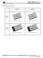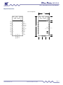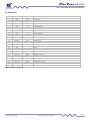
1
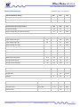
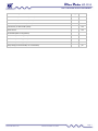
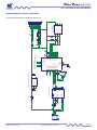
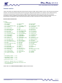
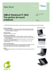
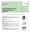
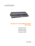
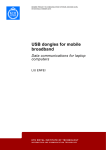
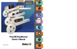
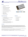
BlueData KC-1114 Class 1 Bluetooth Hi Power Data Module Features CSR BlueCore 4 external chipset Bluetooth v3.0 Class 1 radio, range can exceed 250m 10 Digital programmable I/O Pins 2 Analog programmable I/O Pins Low power connection modes < 8mA Easy to use AT Command interface via Uart Remote command and control Onboard Antenna 8Mbit Flash Memory UART, USB, I2C Interfaces 26.0mm x 15.0mm x 2.5mm Bluetooth Data Profiles Applications SPP – Serial Port Profile A universal bi‐directional data link. Up to 380Kbits/s. Serial Cable Replacement Data Acquisition HID – Human Interface Device Including keyboard, mouse, joystick, and media controls. Remote Sensors RFID Tag Readers Remote control HFP – Handsfree Profile Remote phone control (without audio link). IAP – Apple iOS wireless data peripheral link. Requires approval and an Apple authentication chip. Description The KC‐1114 Class 1 Bluetooth Hi Power Data Module is a highly tuned and completely integrated wireless data transceiver subsystem ready for installation in data devices. The KC‐1114 offers reprogrammable, embedded firmware for serial cable replacement deploying the Bluetooth Serial Port Profile (SPP). Our kcSerial embedded firmware provides an easy to use AT style command interface over Uart. Our kcSerial firmware also provides remote control capability, where our AT commands can be issued remotely from any other Bluetooth device via SPP. All firmware offered by KC Wirefree can be customized for OEM clients. In many cases a few changes can produce great value by differentiating and improving your product. Firmware can be updated via Uart or optionally, via Usb. Please see our kcSerial User Guide and kcKeyboard User Guide for more information on specific features and operation. www.kcwirefree.com Version December 10, 2014 Page 1 BlueData KC-1114 Class 1 Bluetooth Hi Power Data Module SPP – Serial Port Profile The KC Wirefree KC‐1114 data modules come standard with kcSerial which implements (SPP) Serial Port Profile. The SPP is a very popular widely used profile for transmitting data in place of a serial cable. SPP defines how to set up virtual serial ports and connect two Bluetooth enabled devices. A scenario would be using two devices, such as PCs or laptops, as virtual serial ports and then connecting the two devices via Bluetooth technology. HID – Human Interface Profile Our kcKeyboard firmware implements the HID profile defines the protocols, procedures and features to be used by Bluetooth HID including keyboards, mice, game controllers, and media controllers. HID commands are issued via Uart commands, and/or Pio button feature assignments. HFP – Handsfree Profile Our kcKeyboard firmware optionally implements the HFP profile and provides wireless control for phones, but without the capabilities of providing an audio link. This can be a convenient addition for a full featured wireless controller device. IAP – Apple iOS Wireless Profile Our kcSerial firmware implements the IAP profile that provides a peripheral data link to iOS devices. The IAP profile requires an Apple authentication chip, and finished products require an MFi license from Apple. The IAP profile controls the iOS authentication procedure, and implements the Apple lingo data link requirements. Other Available Bluetooth Data Profiles KC‐1114 is capable of supporting additional Bluetooth profiles. Contact KC Wirefree for customization options. www.kcwirefree.com Version December 10, 2014 Page 2 BlueData KC-1114 Class 1 Bluetooth Hi Power Data Module Available Bluetooth Data Modules Class 1 +18dB High Power Class 2 +4dB Standard Power External Antenna KC‐1014 Class 1 Bluetooth Data Module KC‐2014 Class 2 Bluetooth Data Module Onboard Antenna KC‐1114 Class 1 Bluetooth Data Module KC‐2114 Class 2 Bluetooth Data Module www.kcwirefree.com Version December 10, 2014 Page 3 BlueData KC-1114 Class 1 Bluetooth Hi Power Data Module Physical Dimensions KC‐1114 Top View 15.0 MM 5.2 2.5 UART_RTS PIO3 4 25 UART_CTS PIO4 5 24 UART_RXD PIO5 6 23 PIO0 PIO6 7 22 UART_TXD PIO7 8 21 PIO1 PIO8 9 20 PIO11 PIO9 10 19 RESET GND 11 18 GND VDD 12 17 PIO10 16 USB+ 26 15 27 3 SPI_CLK 2 PIO2 14 AIO0 SPI_CSB USB- 13 28 SPI_MOSI 1 SPI_MISO AIO1 26.0 PADS 1.0 X 2.0 16.5 1.5 1.8 5.25 4.5 5.25 www.kcwirefree.com Version December 10, 2014 Page 4 BlueData KC-1114 Class 1 Bluetooth Hi Power Data Module Pin Assignment Pin 1 2 3 4 5 6 7 8 9 10 11 12 13 14 15 16 17 18 19 20 21 22 23 24 25 26 27 28 Function AIO1 AIO0 PIO2 PIO3 PIO4 PIO5 PIO6 PIO7 PIO8 PIO9 GND VDD SPI_MISO SPI_MOSI SPI_CSB SPI_CLK PIO10 GND RESET PIO11 PIO1 UART_TXD PIO0 UART_RXD UART_CTS UART_RTS USB+ USB‐ Type Input Input I/O I/O I/O I/O I/O I/O I/O I/O ‐‐ Input Output Input Input Input I/O ‐‐ Input I/O I/O Output I/O Input Input Output I/O I/O Description Analog Input Analog Input Programmable I/O Programmable I/O Programmable I/O Programmable I/O Programmable I/O [I2C] Programmable I/O [I2C] Programmable I/O [I2C] Programmable I/O Ground 3.3V Regulated Input (2.7V – 3.6V) SPI Master In SPI Master Out SPI Chip Select SPI Clock Programmable I/O Ground Hardware Reset when Low >5ms Programmable I/O Class 1 TX Enable UART Data Transmit Class 1 RX Enable UART Data Receive UART Clear To Send UART Request To Send USB Data Positive USB Data Negative [Option features in brackets] www.kcwirefree.com Version December 10, 2014 Page 5 BlueData KC-1114 Class 1 Bluetooth Hi Power Data Module Interface Pins AIO Interface Pins [1‐2] AIO 0 and AIO 1 are enabled for analog input by default, providing 8 bit samples at rates up to 50 samples/sec. Analog pins are 1.8V logic for input mode. Voltage reading accuracy is guaranteed to 6 bits resolution. PIO Interface Pins [3‐10,20‐21,23] PIO pins are read and write enabled via kcSerial commands. Inputs can be configured for weak pull‐up, weak pull‐down, strong pull‐up, strong pull‐down. Voltage input tolerance and output level is equal to the VDD level. I2C Interface [7‐9] The I2C interface pins are hardware assigned to PIO 6 = SDL, PIO 7 = SDA, and PIO 8 = RESET. The I2C interface must be custom programmed per application. It is used for EEPROM, LCD, and Apple Authentication chips (iOS wireless accessories). VDD Pin [12] Voltage supply pin accepts voltages between 2.7V and 3.6V. Regulation should have a fast response time < 20µs. It is essential that the power rail recover quickly. We recommend Texas Instruments TLV71333PDBVR. Note, the USB, UART, and PIO pins high outputs will be driven relative to this VDD input voltage level. SPI Pins [13‐16] The SPI pins are only available for firmware loading and test tools. SPI test points are highly recommended for emergency diagnostics access. UART Pins [22,24‐26] The UART is compatible with the 16450 industry standard. Four signals are provided with the UART interface. The UART pins operate at TTL voltage level and must be translated to higher RS‐232 voltage levels for communicating with PC hosts. A 3.3V buffered signal IC is recommended. It is highly recommended that UART test points are available for external connection to allow firmware reinstallation or updates. If a microcontroller is attached, provide a tri‐state mode to allow external access to the UART lines. USB Interface [27‐28] The USB interface is available for custom applications. www.kcwirefree.com Version December 10, 2014 Page 6 BlueData KC-1114 Class 1 Bluetooth Hi Power Data Module Application Notes We highly recommend providing a header or test points for the SPI lines. This allows emergency access for diagnostic tools. We highly recommend providing UART test points to allow firmware reinstallation or updates. If a microcontroller is attached, provide a tri‐state mode with microcontroller to allow external access to the UART lines. RS232 hardware flow control is disabled in kcSerial v3.0 firmware by default, and can be enabled with AT HwFlowControl E command (this configuration setting is saved in flash memory). It is highly recommended to enable hardware flow control, since data can be lost with poor wireless connections without flow control. UART interfaces are 3.3V TTL. A voltage level shifter or buffer IC is required when interfacing to higher voltage RS232 ports. Regulator should have a fast response time < 20µs. It is essential that the power rail recover quickly. We recommend Texas Instruments TLV71333PDBVR. Power supply to module should have less than 10mVrms noise between 0‐10MHz, and spikes should be minimal. A voltage level monitor IC connected to RESET is recommended for fluctuating power sources (especially automotive). Flash memory can become corrupted with high or low spiking power sources. We recommend Diodes Inc. APX809‐29SAG‐7 (2.93V). Unused pins should be unconnected. The area around the antenna should be free of metal and grounds. Minimum clearance is 5mm, but additional clearance improves RF performance. Do not use ultra sonic cleaning, which may cause internal interconnect damage to IC’s and crystals. Driving LEDs directly from PIO pins is not recommended. We recommend using MOSFET gates or a buffer driver. www.kcwirefree.com Version December 10, 2014 Page 7 BlueData KC-1114 Class 1 Bluetooth Hi Power Data Module Electrical Characteristics (Conditions VDD= 3.3V and 25 °C) Absolute Maximum Ratings Min Max Unit Storage temperature range ‐40 150 °C Supply voltage VDD ‐0.4 3.7 Volts Recommended Operating Conditions Min Max Unit Temperature Range ‐40 85 °C Supply Voltage VDD (3.3V Recommended) 2.8 3.6 Volts Digital PIO & UART Pins Min Typ Max Unit Input Voltage Low Logic ‐0.4 ‐ 0.8 Volts Input Voltage High Logic 2.3 ‐ 3.7 Volts Output Voltage Low Logic ‐ ‐ 0.2 Volts Output Voltage High Logic 3.1 ‐ ‐ Volts Input Leakage Current ‐1 ‐ +1 µA Input Capacitance 1.0 ‐ 5.0 pF Weak Internal Pull‐Up ‐5.0 ‐1.0 ‐0.2 µA Weak Internal Pull‐Down +0.2 +1.0 +5.0 µA Strong Internal Pull‐Up ‐100 ‐40 ‐10 µA Strong Internal Pull‐Down +10 +40 +100 µA Min Max Unit Resolution 8 Bits Sample Rate 50 Per Sec Voltage 0 1.8 V Analog I/O Pins RF Characteristics Test Conditions BT Spec Typical Unit Maximum RF power 50 Ω load ‐6 to +4 +19 dBm Sensitivity level 0.1% BER ≤ ‐70 ‐96 dBm Antenna load 50 Ω www.kcwirefree.com Version December 10, 2014 Page 8 BlueData KC-1114 Class 1 Bluetooth Hi Power Data Module Current Consumption Avg Unit ACL Data 115Kbps Data Transfer(Master) mA ACL Data 115Kbps Data Transfer(Slave) mA Connection, No Data Traffic (Master) mA Connection, No Data Traffic (Slave) mA Peak current mA Sniff Mode (40ms sniff) (Master) mA Sniff Mode (40ms sniff) (Slave) mA Sniff Mode (1.3s sniff) (Master) mA Sniff Mode (1.3s sniff) (Slave) mA Deep Sleep (not discoverable, not connectable) µA www.kcwirefree.com Version December 10, 2014 Page 9 US B MICR O B GND NC D+ D- 5V US B+ US B- 5.0V 2.2UF 0603 5.0V 0603 0603 0603 27R US B+ 27R 0.1UF 0.1UF US B- 0603 9 8 10 12 11 3 CBUS 0 CBUS 1 CBUS 2 CBUS 3 GND GND1 TXD R XD CTS R TS FTDI_FT230X US BDUS BD+ 3V3OUT VCC RESET VCCIO U1 15 14 7 16 5 13 1 4 6 2 US B-UAR T C ONVE R TE R 1.0UF 0603 3 2 1 NC VOUT T LV71333P DBVR CE GND VIN 4 5 0603 GND NC D+ D- 5V 27R 0603 0603 UAR T_R T S 27R UAR T_C T S UAR T_R XD UAR T_T XD P IO_11 P IO_10 1.0UF 3.3V 17 18 19 20 21 22 23 24 25 26 27 28 PIO10 GND1 RESET PIO11 PIO1 UAR T_TXD PIO0 UAR T_R XD UAR T_CTS UAR T_R TS US B_D+ US B_D- KC-2014 ANT VDD GND PIO9 PIO8 PIO7 PIO6 PIO5 PIO4 PIO3 PIO2 AIO0 AIO1 12 11 10 9 8 7 6 5 4 3 2 1 KC-1014 / KC-2014 BLUE TOOTH DATA MODULE S P I_CLK 5V_S W MICR O B S P I_CS B 16 15 S P I_MOS I S PI_CLK S PI_CS B S P I_MIS O 14 13 S PI_MOS I S PI_MIS O GND2 RF GND3 ON AIO_01 AIO_00 P IO_02 P IO_03 P IO_04 P IO_05 P IO_06 P IO_07 P IO_08 P IO_09 1R 1% 0603 C UR R E NT ME AS UR E 3.3V 3.3V 0603 300R P IO_06 P IO_07 P IO_08 300R 0603 0603 300R GR E E N 3 6 2 7 3.3V P IO_09 P IO_10 P IO_08 P IO_07 P IO_06 P IO_05 P IO_04 P IO_03 P IO_02 AIO_00 3-NC PIO6 PIO7 RSET 5-NC 4-NC GND VDD APPLE MIFI PR OC E S S OR NC7WZ17P6X DR IVE R VDD GND S witch INPUTS GR E E N OUTPUTS 0603 1B US B Version December 10, 2014 29 30 31 5.0V 2.2K 0603 www.kcwirefree.com 2.2K 3V3 VOLTAGE R E GULATOR 5 4 1 8 1 2 3 4 5 6 7 8 9 10 11 12 3.3V C ON4 BlueData KC-1114 Class 1 Bluetooth Hi Power Data Module Example Hardware Interface Connections This schematic example is our BlueDemo Data Board. Page 10 0603 BlueData KC-1114 Class 1 Bluetooth Hi Power Data Module Firmware Interface The KC‐1114 offers our powerful kcSerial firmware interface using the UART, which provides an easy to use AT style text command interface. The firmware interface allows persistent storage of configuration parameters such as device name, default baud rate, security PIN, and automatic connection settings. Additionally kcSerial provides operational commands such as discovery, connections, security, read/write commands for I/O pins. These commands are also available in remote command mode, so a kcSerial device will respond to these commands issued locally via UART, or wirelessly via remote command mode. kcSerial v4.0 AT Command List AT Help ‐> [CommandList] ‐> AT AioRead AT AutoConnect AT BatteryMon ‐> AT BtAddr AT Build AT CoD/Temp ‐> AT ConfigRawBaud/Temp AT ConfigUart/Temp AT ConnDiscForce/Temp ‐> AT Connect AT Connectable AT ConnectIOS ‐> AT ConnectScan AT Data AT DebugMode/Temp ‐> AT DeepSleep/Temp AT Dfu AT Disconnect ‐> AT Discoverable AT DiscoverConfig AT DiscoverSvc ‐> AT Discovery AT EscapeMode/Temp AT FactoryReset ‐> AT HwFlowControl AT InputCmdMode AT InputConnect ‐> AT InputDiscoverable AT InputSleepBlock AT InquiryScan ‐> AT IosBundleID AT IosNameApp AT IosNameDevice ‐> AT IosNameManf AT IosNameModel AT IosService ‐> AT IosSettings AT IosVersion AT LinkStatus ‐> AT LinkTest AT LinkTimeout/Temp AT LowLatency/Temp ‐> AT Messages/Temp AT Name/Temp AT NegotiateSync ‐> AT OutputActivity AT OutputConnect AT OutputCpu ‐> AT OutputDiscoverable AT OutputLowBatt AT PacketSize/Temp ‐> AT Pair AT Pairable AT PairingDelete ‐> AT PairingOption/Temp AT Passkey AT PinCode ‐> AT PioConfig AT PioRead AT PioSettings ‐> AT PioStatus AT PioWrite AT Radio ‐> AT RemoteMode/Temp AT Reset AT RfcService ‐> AT RfPower/Temp AT RoleSwitch AT Rssi ‐> AT ScoConfig AT Security/Temp AT SecurityAuth/Temp ‐> AT ShowSettings AT ShowStatus AT Sniff/Temp ‐> AT SniffSettings AT SniffSubrate AT SppName ‐> AT SppService/Temp AT Timer AT Version ‐> ‐> ‐> EscapeSeq prefix: ~~~~~1 ‐> EscapeCmd prefix: ~~~~~2 ‐> RemoteSeq prefix: ~~~~~3 ‐> RemoteCmd prefix: ~~~~~4 ‐> ‐> Specific command help: AT <command> ? ‐> See kcSerial UserGuide www.kcwirefree.com ‐> [EndCommandList] Please refer to our kcSerial v4.0 User Guide for additional information. www.kcwirefree.com Version December 10, 2014 Page 11 BlueData KC-1114 Class 1 Bluetooth Hi Power Data Module Qualifications Bluetooth The KC‐1114 is registered with and licensed by Bluetooth SIG as a qualified design. Qualification Design ID: 20218 Qualified Profiles: BB, DUN, GAP, HCI, L2CAP, LM, RFCOMM, SDP, SPP KC Wirefree provides a Qualified Design that should be sufficient for product licensing without additional Bluetooth testing requirements. Usage of Bluetooth registered trademarks must be licensed directly from Bluetooth SIG. Please contact Bluetooth SIG regarding product licensing fees. FCC The KC‐1114 has a granted modular approval by the Federal Communications Commission. The module meets the conducted and radiated emission requirements of the FCC "Code of Federal Regulations" Title 47, Part 15, Subpart C, Section 15.247 for Bluetooth spread spectrum transmitters. With a written agreement, Original Equipment Manufacturers may use our FCC ID transmitter license. The following FCC ID must be visible on the exterior of final the product. FCC ID: S2242 CE The KC‐1114 complies with the following EMC Directives: ETSI EN 300.328 V1.6.1 ETSI EN 300.328 V1.8.1 [Approval Pending] Industry Canada IC Warning Statement: The device’s user manual does not contain the following or equivalent statement as per RSS‐GEN section 7.1.5: Operation of this device is subject to the following two conditions: (1) this device may not cause interference, and (2) this device must accept any interference, including interference that may cause undesired operation of the device. IC ID: 8193A‐BTMODULECL2 SAR SAR compliant. www.kcwirefree.com Version December 10, 2014 Page 12 BlueData KC-1114 Class 1 Bluetooth Hi Power Data Module Datasheet Versions Revisions Changes Aug 26, 2014 First release www.kcwirefree.com Version December 10, 2014 Page 13 BlueData KC-1114 Class 1 Bluetooth Hi Power Data Module Ordering Information Product Series KC‐1114 Product Version 0 Country of Manufacture USA Order Part Number Description KC‐1114.0 Class 1 Bluetooth Hi Power Data Module w/ kcSerial Firmware Latest Edition KC‐1114.0‐FW Class 1 Bluetooth Hi Power Data Module, w/ Custom Firmware Contact Information KC Wirefree 2640 W Medtronic Way Tempe, Arizona 85281 (602) 386‐2640 Phone www.kcwirefree.com Website [email protected] Sales Support [email protected] Technical Support www.kcwirefree.com Version December 10, 2014 Page 14