Download User Guide

Transcript
Personal Computer
Types 2196, 2197, and 6344
User Guide
Note: Before using this information and the product it supports, be sure to read
the general information under “Appendix D. Warranty” on page D-1.
Second Edition (April 2001)
The following paragraph does not apply to any state or country where such provisions are
inconsistent with local law: INTERNATIONAL BUSINESS MACHINES CORPORATION
PROVIDES THIS PUBLICATION “AS IS” WITHOUT WARRANTY OF ANY KIND, EITHER
EXPRESS OR IMPLIED, INCLUDING, BUT NOT LIMITED TO, THE IMPLIED WARRANTIES
OF MERCHANTABILITY OR FITNESS FOR A PARTICULAR PURPOSE. References to IBM
products, programs, or services do not imply that IBM intends to make them available outside
the United States.
This publication could contain technical inaccuracies or typographical errors. Changes are
periodically made to the information herein; these changes will be made in later editions. IBM
may make improvements and/or changes in the product(s) and/or program(s) at any time.
Request for copies of this publication and for technical information about IBM products should
be made to your IBM Authorized Dealer, your IBM Marketing Representative or your IBM
Retailer. Address comments about this publication to the IBM HelpCenter.
© Copyright International Business Machines Corporation 2000. All rights reserved.
Note to U.S. Government Users – Documentation related to restricted rights – Use, duplication
or disclosure is subject to restrictions set forth in GSA ADP Schedule Contract with IBM Corp.
Contents
Notices .........................................................................................................xi
Conventions used in this book .......................................................................xii
Safety information .......................................................................................... xiii
Installation ............................................................................................. xiii
Safety while working with hardware ...................................................... xiv
Lithium battery notice ............................................................................ xvi
Regulatory safety notice for the CD-ROM and DVD-ROM drive .......... xvi
Laser compliance statement ................................................................. xvii
Consignes de sécurité .......................................................................... xviii
Consignes de sécurité lors de la manipulation du matériel .................. xix
Regulatory notices .........................................................................................xxiii
North American Federal Communications Commission (FCC)
Statement ...................................................................................................... xxvi
European Community Directive Conformance Statement .................... xxvii
Trademarks ........................................................................................... xxvii
Year 2000 Notice Information ........................................................................xxviii
Ergonomics.....................................................................................................xxxi
Part 1. Learning about this book
Using this book ...........................................................................................1-1
How this book is organized ............................................................................1-1
Where to find more information .....................................................................1-4
Part 2. Support information
HelpWare support and services ................................................................2-1
What do I do first? .........................................................................................2-1
What is IBM HelpWare? ....................................................................... 2-1
Need quick help? .................................................................................. 2-1
What can I do on my own? ................................................................... 2-2
How do I get help electronically? ...................................................................2-4
Electronic support ................................................................................. 2-4
How and when do I contact the IBM PC HelpCenter? ...................................2-5
v
What help can I get by telephone? ....................................................... 2-5
Before you call... ................................................................................... 2-7
How and when do I purchase additional support? ........................................ 2-9
Purchasing additional HelpWare services ............................................ 2-9
Express Maintenance ................................................................................. 3-1
Part 3. Controlling system settings
Getting started ............................................................................................ 4-1
Controlling monitor settings ........................................................................... 4-2
Getting the best performance from your monitor .................................. 4-2
Power saver feature ............................................................................. 4-3
Changing display settings ..................................................................... 4-3
Controlling volume ......................................................................................... 4-6
Adjusting the speaker volume ............................................................. 4-6
Getting ready to print ..................................................................................... 4-7
Setting up communications ........................................................................... 4-8
Connecting your modem to the telephone network .............................. 4-8
Configuring your communications software .......................................... 4-9
Configuring your computer for a connection to the Internet .......................... 4-10
The IBM Internet Connection Services ................................................. 4-10
The Microsoft Network .......................................................................... 4-10
The Internet Connection Wizard ........................................................... 4-11
Using the Rapid Access II keyboard ..................................................... 4-11
Power management features .................................................................... 5-1
Software shutdown ........................................................................................ 5-2
Using the software shutdown feature ................................................... 5-2
System Standby ............................................................................................ 5-3
Using the Windows 98 Start menu ....................................................... 5-3
Using the power button ......................................................................... 5-3
Using the Power Management feature in Windows 98 ................................. 5-5
Monitor standby ............................................................................................. 5-6
BIOS Setup configuration .......................................................................... 6-1
Configuration/Setup Utility overview .............................................................. 6-2
vi IBM Personal Computer User Guide
Entering Setup ...............................................................................................6-4
When the computer is on ...................................................................... 6-4
When the computer is off ...................................................................... 6-4
Working with the Setup menus ......................................................................6-5
Configuration/Setup Utility menu ......................................................... 6-5
Viewing system information and product data ...................................... 6-6
Changing parameter settings ................................................................ 6-7
Loading the default settings .................................................................. 6-7
Canceling changes ............................................................................... 6-8
Exiting Setup ......................................................................................... 6-8
Setup parameters ..........................................................................................6-9
Devices and I/O Ports ........................................................................... 6-9
Start Options ......................................................................................... 6-12
Halt On .................................................................................................. 6-15
Date and Time ...................................................................................... 6-15
Advanced Setup ................................................................................... 6-16
Power Management Setup ................................................................... 6-16
Clock Generator Configuration ............................................................. 6-19
Set Password ........................................................................................ 6-19
Using other configuration utilities ...................................................................6-20
Part 4. Upgrading and replacing hardware
Preparing to upgrade .................................................................................7-1
Evaluating your new hardware ......................................................................7-2
For conflicts with system resources used by adapter cards ................. 7-2
For conflicts with other system resources ............................................. 7-2
Planning your hardware changes ..................................................................7-3
Recording your changes ....................................................................... 7-3
Resolving resource conflicts ..........................................................................7-4
Using Setup .......................................................................................... 7-4
Using the Windows 98 Device Manager ............................................... 7-4
Opening the system unit ................................................................................7-5
Taking safety precautions ..................................................................... 7-5
Removing the top cover ........................................................................ 7-6
Looking inside the system unit ......................................................................7-7
vii
Adding and removing adapter cards and drives ..................................... 8-1
Resolving conflicts with installed adapter cards ............................................ 8-2
Setting modem card configurations ...................................................... 8-2
Working with the hardware in the system unit ............................................... 8-3
Adding and removing adapter cards ............................................................. 8-4
Installing adapter cards ........................................................................ 8-4
Removing adapter cards ...................................................................... 8-5
Removing and adding drives ......................................................................... 8-6
Identifying signal cable connectors ....................................................... 8-6
Removing the CD-ROM drive ............................................................... 8-11
Removing the hard disk drive ............................................................... 8-12
Updating the CMOS settings in Setup ........................................................... 8-13
For adapter cards ................................................................................. 8-13
For Drives ............................................................................................. 8-13
Adding and replacing system board components .................................. 9-1
Identifying system board parts (machine type 2196) ..................................... 9-2
Locating system board jumpers and connectors (machine type 2196) ......... 9-4
Identifying system board parts (machine type 2197 and 6344) ..................... 9-5
Locating system board jumpers and connectors (machine type 2197
and 6344) ...................................................................................................... 9-7
Card connector and jumper information ........................................................ 9-8
Identifying adapter card connectors ..................................................... 9-8
Setting a jumper ................................................................................... 9-8
Upgrading the system memory ..................................................................... 9-9
Installing memory modules ................................................................... 9-9
Removing memory modules ................................................................. 9-10
Verifying the system memory ............................................................... 9-10
Replacing the system battery ........................................................................ 9-11
Updating the CMOS settings in Setup ........................................................... 9-13
Part 5. Troubleshooting
Diagnosing and recovering from problems ............................................. 10-1
Before you panic: some simple fixes ............................................................. 10-2
viii IBM Personal Computer User Guide
Quick problem solving chart ..........................................................................10-6
Solving hardware and software problems .....................................................10-7
Solving hardware problems .................................................................. 10-7
Solving software problems .................................................................... 10-13
Solving modem problems ..................................................................... 10-15
Error codes and messages ............................................................................10-17
IBM Diagnostic Programs ..............................................................................10-20
Recovering factory-installed programs and files ............................................10-22
Part 6. Technical reference
Appendix A. Specification tables ...............................................................A-1
Memory module placement ...........................................................................A-1
Memory map ..................................................................................................A-3
System input/output addresses .....................................................................A-4
System interrupts ...........................................................................................A-6
DMA channel assignments ............................................................................A-7
Serial port addresses .....................................................................................A-8
Connector functions .......................................................................................A-9
Appendix B. Modem information ...............................................................B-1
Modem features .............................................................................................B-1
Operating your modem ..................................................................................B-3
Using the Auto Answer feature ............................................................. B-3
Disabling Call Waiting ........................................................................... B-4
Modem commands ........................................................................................B-5
Executing commands ........................................................................... B-5
Command format .................................................................................. B-5
AT commands ....................................................................................... B-6
Detail for +MS Controls ........................................................................ B-9
Extended AT commands ...................................................................... B-10
V.42bis commands ............................................................................... B-11
Modem response codes ................................................................................B-12
S registers .....................................................................................................B-13
Appendix C. Monitor terminology ..............................................................C-1
ix
Appendix D. Warranty ................................................................................. D-1
Warranty statements ..................................................................................... D-1
IBM Statement of Limited Warranty for United States, Puerto Rico,
and Canada (Part 1 - General Terms) ................................................... D-2
IBM Statement of Warranty Worldwide except Canada, Puerto Rico,
Turkey, United States (Part 1- General Terms) ..................................... D-6
Part 2 - Country-Unique Terms .............................................................. D-10
Index
x
IBM Personal Computer User Guide
Notices
References in this publication to IBM products, programs, or services do not imply
that IBM intends to make these available in all countries in which IBM operates. Any
reference to an IBM product, program, or service is not intended to state or imply
that only IBM's product, program, or service may be used. Any functionally
equivalent product, program, or service that does not infringe any of IBM's
intellectual property rights may be used instead of the IBM product, program, or
service. Evaluation and verification of operation in conjunction with other products,
except those expressly designated by IBM, are the user's responsibility.
IBM may have patents or pending patent applications covering subject matter in this
document. The furnishing of this document does not give you any license to these
patents. You can send license inquiries, in writing, to the IBM Director of Licensing,
IBM Corporation, North Castle Drive, Armonk, NY 10504-1785, U.S.A.
IBM makes no representations whatsoever about any non-IBM Web site. When you
access a non-IBM Web site, please understand that it is independent from IBM, and
IBM has no control over the content on that Web site. In additional, a reference to a
non-IBM Web site does not mean that IBM endorses or accepts any responsibility
for the content, or the use, of such Web site. It is up to you to take precautions to
ensure that whatever you select for your use is free of such items as viruses, worms,
trojan horses and other items of a destructive nature. IN NO EVENT WILL IBM BE
LIABLE TO ANY PERTY FOR ANY DIRECT, INDIRECT, SPECIAL OR OTHER
CONSEQUENTIAL DAMAGES FOR ANY OTHER WEBSITE, INCLUDING,
WITHOUT LIMITATION, ANY LOST PROFITS, BUSINESS INTERRUPTION, LOSS
OF PROGRAMS OR OTHER DATA ON YOUR INFORMATION HANDLING
SYSTEM OR OTHERWISE, EVEN IF WE ARE EXPRESSLY ADVISED OF THE
POSSIBILITY OF SUCH DAMAGES.
xi
Conventions used in this book
Symbols
The following list contains an explanation of the symbols used in this document.
Note:
This symbol is used when there is information you
might find especially useful. The information may
also warn you about possible problems you could
encounter.
Attention!
This symbol is used when there is important
information that can help you avoid damage to the
hardware or software that came with your
computer.
Caution!
This symbol is used when there is important
information that can help you avoid potential injury.
Danger!
This symbol is used when there is important
information that can help you avoid the risk of
serious personal injury or death.
Highlighting
There are several ways that text is highlighted in this book. Each highlighting
convention has a specific purpose.
Highlight
Purpose
Bold
Bold font is used to identify items on the screen
you are instructed to click or double-click. Bold
font is also used in headings, table titles, and
numbered lists.
Example
Example font is used to show text that you need to
type from your keyboard.
Italic
Italic font is used to show proper names of
programs or books. Italic font is also used in table
footnotes and sidenotes.
"Quotes"
Quotation marks are used to identify window,
screen, and heading names.
Underline
Underline font is used to call special emphasis to
a particular word or instruction.
xii
IBM Personal Computer User Guide
Safety information
Installation
The construction of the IBM Personal Computer provides extra protection against
the risk of electrical shock. The IBM computer has a power cord with a three-prong
plug that is required to ground metal parts. It is the responsibility of the person
installing the computer to connect it to a properly grounded electrical outlet. Seek
professional assistance before using an adapter or extension cord; these devices
could interrupt the grounding circuit.
If the computer is connected to an electrical outlet that is incorrectly connected to
the building wiring, serious electrical shock could result.
CONTINUED PROTECTION AGAINST THE RISK OF ELECTRICAL SHOCK:
For continued protection against the risk of electrical shock, follow these steps:
• Connect your computer only to an electrical outlet of the correct voltage. If you
are unsure about the voltage of the electrical outlet you are using, contact your
local power company.
• If your computer has cables other than the power cords, you must connect
them before plugging the power cords into an electrical outlet. Before removing
these cables, you must first unplug the power cords from the outlet.
• If your computer has a telephone connection, do not touch the telephone cords
when there is lightning in the area.
• Do not use or store the computer in an area where it can become wet.
• Make sure all replacement parts have characteristics identical or equivalent to
the original parts. Other parts may not have the same safety features.
• Personal injury or electrical shock may result if you undertake actions other
than those specifically described in this book. This is particularly true if you try
to service or repair the power supply, monitor, or built-in modem. Always refer
service or repairs to qualified service personnel.
xiii
Safety while working with hardware
Each time you open your computer, you must follow specific safety procedures to
ensure that you do not damage your computer. For your safety, and the safety of
your equipment, follow the steps for “Disconnecting your computer” on page xv
before you remove the cover of the system unit (if included with the model you
purchased).
Connecting your computer
To connect your computer:
1. Turn off the computer and any external devices (such as a monitor or printer)
that have their own power switches.
2. Attach a signal cable to each external device (such as a monitor or printer), and
then connect the other end of the signal cable to the computer.
3. Attach communication cables (such as modem cables or network cables) to the
computer. Then, attach the other ends of the cables to properly wired communication outlets.
4. Attach the power cords to the computer and any external devices (such as a
monitor or printer), and then connect the other ends of the power cords to properly grounded electrical outlets.
5. Turn on the computer and any attached devices that have their own power
switches.
To avoid shock hazard:
Danger!
xiv
• Do not connect or disconnect any cables or
perform installation, maintenance, or
reconfiguration of this product during an
electrical storm.
• The power cord must be connected to a
properly wired and grounded receptacle.
• Any equipment to which this product will be
attached must also be connected to properly
wired electrical outlets.
• Electrical current from power, telephone, and
communications cables is hazardous. To
avoid shock hazard, use the steps described
in this section to connect and disconnect
cables when installing, moving, or opening
the cover of this product.
• Never install telephone wiring during a
lightning storm
IBM Personal Computer User Guide
Disconnecting your computer
To disconnect your computer:
1. Turn off the computer and any attached devices that have their own power
switches.
2. Unplug all power cables from electrical outlets.
3. Disconnect all communication cables (such as modem or network cables) from
communication outlets.
4. Disconnect all cables and cords from the computer; this includes power cords,
signal cables from external devices, communication cables, and any other
cables attached to the computer.
Danger!
Do not detach the power-supply bracket from the
power supply or remove any of the power-supply
screws.
Caution!
Be sure to turn off the computer and monitor
power switches before cleaning the computer and
monitor screen.
Modem safety information
To reduce the risk of fire, electrical shock, or injury when using telephone
equipment, always follow basic safety precautions, such as:
• Never install telephone wiring during a lightning storm.
• Never install telephone jacks in wet locations unless the jack is specifically
designed for wet locations.
• Never touch uninsulated telephone wires or terminals unless the telephone line
has been disconnected at the network interface.
• Use caution when installing or modifying telephone lines.
• Avoid using a telephone (other than a cordless type) during an electrical storm.
There may be a remote risk of electric shock from lightning.
• Do not use the telephone to report a gas leak in the vicinity of the leak.
xv
Lithium battery notice
Caution!
Your computer uses lithium batteries. There may be
a risk of fire, explosion, or burns if the batteries are
handled incorrectly.
To ensure safety:
• Do not recharge, disassemble, heat, or incinerate a lithium battery.
• Replace the battery with an identical or equivalent type lithium battery.
• Do not throw or immerse the battery in water.
• Discard used lithium batteries according to local country dispositions.
Regulatory safety notice for the CD-ROM and DVD-ROM
drive
This notice contains required safety information about the CD-ROM/DVD-ROM
drive in your computer (if included with the model you purchased). The CD-ROM/
DVD-ROM drive is a Class 1 laser product, and Class 1 laser products are not
considered to be hazardous. The design of the laser system and CD/ROM-DVDROM drive ensures that during normal operation, there is no exposure to laser
radiation above Class 1 level.
Please note that the CD-ROM/DVD-ROM drive does not contain any user
adjustable or serviceable parts. Service on this drive should only be performed by a
trained service provider.
xvi
IBM Personal Computer User Guide
Laser compliance statement
Some IBM Personal Computer models are equipped from the factory with a CDROM or DVD-ROM drive. CD-ROM/DVD-ROM drives are also sold separately as
options. The CD-ROM/DVD-ROM drive is a laser product. The CD-ROM/DVD-ROM
drive is certified in the U.S. to conform to the requirements of the Department of
Health and Human Services 21 Code of Federal Regulations (DHHS 21 CFR)
Subchapter J for Class 1 laser products. Elsewhere, the drive is certified to conform
to the requirements of the International Electrotechnical Commission (IEC) 825 and
CENELEC EN 60 825 for Class 1 laser products.
When a CD-ROM/DVD-ROM drive is installed, note the following:
Caution!
Use of controls or adjustments or performance of
procedures other than those specified herein might
result in hazardous radiation exposure.
Removing the covers of the CD-ROM/DVD-ROM drive could result in exposure to
hazardous laser radiation. There are no serviceable parts inside the CD-ROM/DVDROM drive covers. Do not remove the CD-ROM/DVD-ROM drive covers.
Some CD-ROM/DVD-ROM drives contain an embedded Class 3A or Class 3B laser
diode. Note the following:
Danger!
Laser radiation when open. Do not stare into the
beam, do not view directly with optical instruments,
and avoid direct exposure to the beam.
xvii
Consignes de sécurité
Installation
La conception de fabrication de l'ordinateur personnel IBM assure une protection
accrue contre les risques d'électrocution. Le PC IBM possède un cordon
d'alimentation équipé d'une fiche à trois broches qui permet une mise à la terre des
principaux éléments métalliques de la machine. Il incombe au responsable de
l'installation de vérifier le branchement. Si vous devez installer un adaptateur ou une
rallonge, faites appel à un professionnel pour ne pas risquer de créer une rupture
dans le circuit de mise à la terre. Un socle de prise de courant incorrectement relié
à l'alimentation électrique du bâtiment peut être à l'origine d'une électrocution.
Pour éviter tout risque de choc électrique:
Ne manipulez aucun cordon et n’effectuez aucune
opération d’installation, de maintenance ou
reconfiguration de ce produit au cours d’un orage.
Danger!
Les cordon d’alimentation du présent produit et de
tous les appareils qui lui sont connectés doivent être
branchés sur des socles de prise de courant
correctement câblés et mis à la terre.
Le courant électrique circulant dans les câblés de
communication et les cordons téléphoniques et
d’alimentation est dangereux. pour éviter tout risque
de choc électrique, respectez les consignes de la
présente section pour connecter et déconnecter des
câblés lors de l’installation, du retrait ou de
l’ouverture du panneu de ce produit.
Protection contre les risques d'électrocution. Pour vous prémunir contre les
risques d'électrocution, respectez les consignes ci-après:
• Ne branchez l'ordinateur que sur un socle de prise de courant présentant la
tension adéquate.
• Ne branchez le cordon d'alimentation sur le socle de prise de courant qu'après
avoir connecté tout autre cordon à la machine. Inversement, débranchez le
cordon d'alimentation du socle de la prise de courant avant de déconnecter tout
autre cordon.
xviii IBM Personal Computer User Guide
• Si votre ordinateur est doté d'un cordon téléphonique, ne manipulez jamais ce
cordon pendant un orage.
• Évitez d'utiliser et de placer votre ordinateur dans un endroit humide.
• Ne remplacez un élément que par un élément identique ou possédant des
caractéristiques équivalentes et équipé des mêmes dispositifs de sécurité.
• Le non-respect de ces consignes peut être à l'origine de blessures ou d'une
électrocution, en particulier si vous intervenez sur le bloc d'alimentation, l'écran
ou le modem intégré. Confiez la maintenance et la réparation de l'ordinateur à
une personne qualifiée.
Consignes de sécurité lors de la manipulation du matériel
Lorsque vous ouvrez l'unité centrale, il convient de suivre un certain nombre de
consignes de sécurité afin de ne pas endommager l'ordinateur. Pour votre sécurité
et celle de votre matériel, suivez les instructions de la section “Disconnecting your
computer” on page xv, avant d'ouvrir l'unité centrale (le cas échéant).
Branchement de l'ordinateur. Pour brancher l'ordinateur, procédez comme suit:
1. Mettez l'ordinateur hors tension ainsi que tout périphérique (écran ou
imprimante) que vous allez connecter, qui dispose d'un interrupteur
d'alimentation.
2. Connectez tous les câbles (de l'écran, par exemple) à l'ordinateur.
3. Branchez tous les câbles d'interface (par exemple, un câble téléphonique) sur
des socles de prise de courant correctement mis à la terre.
4. Branchez les cordons d'alimentation sur des socles de prise de courant
correctement mis à la terre.
5. Mettez l’ordinateur sous tension ainsi que tout périphérique connecté
disposant d’un interrupteur d’alimentation.
Débranchement de l'ordinateur. Pour débrancher l'ordinateur, procédez comme
suit:
1. Mettez l'ordinateur hors tension ainsi que tout périphérique connecté
disposant d'un interrupteur d'alimentation.
xix
2. Débranchez tous les cordons d'alimentation des prises de courant.
3. Débranchez tous les câbles (câble de téléphone, par exemple) de leurs
prises.
4. Débranchez tous câbles de l’ordinateur (les cordons d’alimentation, les
câbles d’entrée-sortie et tous les autres câbles qui pourraient y être
connectés).
Votre ordinateur est équipé de piles au lithium.
Prenez garde aux risques d’incendie, d’explosion ou
de brûlures liés à une mauvaise utilisation des piles.
Respectez les consignes de sécurité suivantesy:
Ne rechargez pas la pile, ne la démontez pas, ne
l’exposez pas à la chaleur et ne la faites pas brûler.
Attention!
Ne la remplacez que par une pile identique ou de
type équivalent.
Ne la jetez pas à l’eau.
Pour le recyclage ou la mise au rebut des piles au
lithium, reportez-vous à la réglementation en
vigueur.
Danger!
Attention!
No détachez pas le bloc d’alimentation de son
support et ne retirez aucune vis du bloc
d’alimentation.
Veillez à mettre l’ordinateur et l’écran hors tension
avant de procéder à leur nettoyage.
Consignes de sécurité relatives au modem
Lors de l’utilisation de votre matériel téléphonique, il est important de respecter les
consignes ci-après afin de réduire les risques d’incendie, d’électrocution et d’autres
blessures:
• N’intallez jamais de cordons téléphoniques durant un orage.
• Les prises téléphoniques ne doivent pas être installées dan des endroits
humides, excepté si le modéle a été conçu à cet effet.
xx
IBM Personal Computer User Guide
• Ne touchez jamais un cordon téléphonique ou un terminal non isolé avant que
la ligne ait été déconnectée du réseau téléphonique.
• Soyez toujours prudent lorsque vous procédez à l’intallation ou à la
modification de lignes téléphoniques.
• Si vous devez téléphoner pendant un orage, pour éviter tout risque de choc
électrique, utilisez toujours un téléphone sans fil.
• En cas de fulte de gaz, n’utilisez jamais un téléphone situé à proximité de la
fuite.
Consignes relatives à la pile au lithium
Attention!
Votre ordinateur est équipé de piles au
lithium. Prenez garde aux risques
d’incenjdie, d’explosion ou de brûlures llés à
une mauvaise utilisation des piles.
Respectez les consignes de sécurité
suivantesy:
• Ne rechargez pas la pile, ne la démontez pas, ne l’exposez pas à la chaleur et
ne la faite pas brûler.
• Ne la remplacez que par une pille identique ou de type équivalent.
• Ne la jetez pas à l’eau.
• Pour le recyclage ou la mise au rebut des piles au lithium, reportez-vous à la
réglementation en vigueur.
Consignes de sécurité pour l’unité de CD-ROM et de DVD-ROM
La présente consigne contient les informations de sécurité relatives à l’unité de CDROM de votre ordinateur (le cas échéant). L’unité de CD-ROM est un produit à laser
de classe 1. Les produits de classe 1 ne sont pas considérés comme dangereux. Le
système à laser et l’unité de CD-ROM ont été conçus de façon telle qu’il n’existe
aucun risque d’exposition à un rayonnement laser de niveau supérieur à la classe 1
dans des conditions normales d’utilisation.
Veuillez noter qu’aucune pièce de l’unité de CD-ROM n’est réglable ni réparable. Ne
confiez la réparation de cette unité qu’à une personne qualifiée.
xxi
Conformité aux normes relatives aux appareils laser.
Certains modèles d’ordinateurs personnels sont équipés d’origine d’une unité de
CD-ROM ou de DVD-ROM. Mais ces unités sont également vendues séparément
en tant qu’options. L’unité de CD-ROM/DVD-ROM est un appareil à laser. Aux EtatUnis, l’unité de CD-ROM/DVD-ROM est certifiée conforme aux normes indiquées
dans le sous-chapitre J du DHHS 21 CFR relatif aux produits à laser de classe 1.
Dans les autres pays, elle est certifiée être un produit à laser de classe 1 conforme
aux normes CDI 825 et CENELEC EN 60 825.
Lorsqu’une unité de CD-ROM est installée, tenez compte des remarques suivantes:
Attention!
Danger!
Pour éviter tout risque d’exposition au rayon
laser, respectez les consignes de réglage et
d’utilisation des commandes, ainsi que les
procédures décrites.
L’ouverture de l’unité de CD-ROM/DVD-ROM
peut entraîner un risque d’exposition au
rayon laser. Pour toute intervention, faites
appel à du personnel qualifié.
Rayonnement laser lorsque le carter est
ouvert. Évitez toute exposition directe des
yeux au rayon laser. Évitez de regarder
fixement le faisceau ou de l’observer à l’aide
d’instruments optiques.
xxii IBM Personal Computer User Guide
Regulatory notices
North American FCC and telephone company requirements
If your IBM Personal Computer comes with a modem already installed, the following
Federal Communications Commission (FCC) and telephone company requirements
apply:
1. The modem adapter card is located in the back of the system unit. It complies
with Part 68 of the FCC rules. A label is affixed to the built-in modem that
contains, among other things, the FCC registration number, USOC, and Ringer
Equivalency Number (REN) for this equipment. If these numbers are
requested, see “Opening the system unit” on page 7-5 to open the unit to get
the FCC registration number on the modem card.Provide this information to
your telephone company.
2. The REN is useful to determine the quantity of devices you may connect to your
telephone line and still have those devices ring when your number is called. In
most, but not all areas, the sum of the RENs of all devices should not exceed
five (5.0). To be certain of the number of devices you may connect to your line,
as determined by the REN, you should call your local telephone company to
determine the maximum REN for your calling area.
3. If the built-in modem causes harm to the telephone network, the telephone
company may discontinue your service temporarily. If possible, they may notify
you in advance; if advance notice isn't practical, you will be notified as soon as
possible. You may be advised of your right to file a complaint with the FCC.
4. Your telephone company may make changes in its facilities, equipment, operations, or procedures that could affect the proper operation of your equipment. If
they do, you may be given advance notice so as to give you an opportunity to
maintain uninterrupted service.
5. If you experience trouble with this built-in modem, contact your Authorized
Seller, or the IBM HelpCenter-PC, IBM Corporation, 3039 Cornwallis Rd., Bldg,
203, Research Triangle Park, NC 27709-2195 1-919-517-2800, for repair/
warranty information. The telephone company may ask you to disconnect this
equipment from the network until the problem has been corrected, or until you
are sure the equipment is not malfunctioning.
6. No customer repairs are possible to the modem.
xxiii
7. The modem may not be used on coin service provided by the telephone
company. Connection to party lines is subject to state tariffs. Contact your state
public utility commission or corporation commission for information.
8. When ordering network interface (NI) service from the Local Exchange Carrier,
specify service arrangement USOC RJ11C.
Canadian Department of Communications certification label
NOTICE: The Canadian Department of Communications label identifies certified
equipment. This certification means that the equipment meets certain
telecommunications network protective, operational, and safety requirements. The
Department does not guarantee the equipment will operate to the user’s
satisfaction.
Before installing this equipment, users should ensure that it is permissible to be
connected to the facilities of the local telecommunications company. The equipment
must also be installed using an acceptable method of connection. In some cases,
the company's inside wiring associated with a single line individual service may be
extended by means of a certified connector assembly (telephone extension cord).
The customer should be aware that compliance with the above conditions may not
prevent degradation of service in some situations.
Repairs to certified equipment should be made by an authorized Canadian
maintenance facility designated by the supplier. Any repairs or alterations made by
the user to this equipment, or equipment malfunctions, may give the
telecommunications company cause to request the user to disconnect the
equipment.
Users should ensure for their own protection that the electrical ground connections
of the power utility, telephone lines, and internal metallic water pipe system, if
present, are connected together. This precaution may be particularly important in
rural areas.
Caution: Users should not attempt to make such connections themselves, but
should contact the appropriate electric inspection authority, or electrician, as
appropriate.
NOTICE: The LOAD NUMBER (LN) assigned to each terminal device denotes the
percentage of the total load to be connected to a telephone loop which is used by
the device, to prevent overloading. The termination on a loop may consist of any
combination of devices subject only to the requirement that the sum of the LOAD
NUMBERS of all the devices does not exceed 100.
xxiv IBM Personal Computer User Guide
Étiquette d'homologation du ministère des Communications du Canada
AVIS : L'étiquette du ministère des Communications du Canada identifie le matériel
homologué. Cette étiquette certifie que le matériel est conforme à certaines normes
de protection, d'exploitation et de sécurité des réseaux de télécommunications. Le
ministère n'assure toutefois pas que le matériel fonctionnera à la satisfaction de
l'utilisateur.
Avant d'installer ce matériel, l'utilisateur doit s'assurer qu'il est permis de le
raccorder aux installations de l'entreprise locale de télécommunications. Le matériel
doit également être installé en suivant une méthode acceptée de raccordement.
L'abonné ne doit pas oublier qu'il est possible que la conformité aux conditions
énoncées ci-dessus n'empêchent pas la dégradation du service dans certaines
situations.
Les réparations de matériel homologué doivent être effectuées par un centre
d'entretien canadien autorisé désigné par le fournisseur. La compagnie de
télécommunications peut demander à l'utilisateur de débrancher un appareil à la
suite de réparations ou de modifications effectuées par l'utilisateur ou à cause d'un
mauvais fonctionnement.
Pour sa propre protection, l'utilisateur doit s'assurer que tous les fils de mise à la
terre de la source d'énergie électrique, des lignes téléphoniques et des
canalisations d'eau métalliques, s'il y en a, sont raccordés ensemble. Cette
précaution est particulièrement importante dans les régions rurales.
Avertissement : l'utilisateur ne doit pas tenter de faire ces raccordements luimême, il doit avoir recours à un service d'inspection des installations électriques ou
à un électricien, selon le cas.
AVIS : L'INDICE DE CHARGE (IC) assigné à chaque dispositif terminal indique,
pour éviter toute surcharge, le pourcentage de la charge totale qui peut être
raccordé à un circuit téléphonique bouclé utilisé par ce dispositif. L'extrémité du
circuit bouclé peut consister en n'importe quelle combinaison de dispositifs pourvu
que la somme des INDICES DE CHARGE de l'ensemble des dispositifs ne dépasse
pas 100.
xxv
North American Federal Communications Commission
(FCC) Statement
IBM Personal Computer machine types 2196, 2197, and 6344
The following statement applies to this IBM product. The statement for other IBM
products intended for use with this product will appear in their accompanying
manuals.
This equipment has been tested and found to comply with the limits for a Class B
digital device, pursuant to Part 15 of the FCC Rules. These limits are designed to
provide reasonable protection against harmful interference in a residential
installation. This equipment generates, uses, and can radiate radio frequency
energy and, if not installed and used in accordance with the instructions, may cause
harmful interference to radio communications. However, there is no guarantee that
interference will not occur in a particular installation. If this equipment does cause
harmful interference to radio or television reception, which can be determined by
turning the equipment off and on, the user is encouraged to try to correct the
interference by one or more of the following measures:
• Reorient or relocate the receiving antenna.
• Increase the separation between the equipment and receiver.
• Connect the equipment into an outlet on a circuit different from that to which the
receiver is connected.
• Consult an IBM authorized dealer or service representative for help.
Properly shielded and grounded cables and connectors must be used in order to
meet FCC emission limits. Proper cables and connectors are available from IBM
authorized dealers. IBM is not responsible for any radio or television interference
caused by using other than recommended cables and connectors or by
unauthorized changes or modifications to this equipment. Unauthorized changes or
modifications could void the user's authority to operate the equipment.
This device complies with Part 15 of the FCC Rules. Operation is subject to the
following two conditions: (1) this device may not cause harmful interference, and (2)
this device must accept any interference received, including interference that may
cause undesired operation.
xxvi IBM Personal Computer User Guide
Responsible Party:
International Business Machines Corporation
New Orchard Road
Armonk, NY 10504
Telephone: 1-919-543-2193
Tested To C o m ply
W ith F C C S ta nd a rds
F O R H O M E O R O FF IC E U SE
This Class B digital apparatus complies with Canadian ICES-003.
Cet appareil numérique de classe B est conforme la norme NMB-003 du Canada.
European Community Directive Conformance Statement
This product is in conformity with the protection requirements of EU Council
directive 89/336/EEC on the approximation of the laws of the Member States
relating to electromagnetic compatibility.
IBM cannot accept responsibility for any failure to satisfy the protection
requirements resulting from a non-recommended modification of the product,
including the fitting of non-IBM option cards.
Trademarks
The following terms are trademarks or registered trademarks of the IBM corporation
in the United States or other countries or both:
• HelpCenter
• HelpWare
• IBM
• PS/2
• OS/2
Microsoft and Windows are trademarks or registered trademarks in the United
States, other countries or both.
Other company, product, and service names may be trademarks or service marks of
others.
xxvii
Year 2000 Notice Information
14 January 1999
Notice: Year 2000 readiness status of certain software that might be included
with your IBM computer.
IBM has included with your IBM computer selected software products that are
supplied by independent software vendors (also known as ISVs). As of the date of
this notice, some software vendors have not designated as ready for the Year
2000 some versions of their software products as distributed. This means that
(a) the software requires updates to become Year 2000 ready, compliant, or
compliant with minor Issues (as defined by the vendor) or (b) the vendor had not yet
published Year 2000 readiness or compliance status.
The software products that the software vendors had not designated as Year 2000
ready as distributed include (but are not limited to) the following software products
or certain national language versions or service releases of such software products:
Product
Web site address
AOL
(by America Online)
http://www.aol.com/info/year2000.html
CompuServe
(by CompuServe
Interactive Services)
httq://www.compuserve.com/content/cs_y2kfaq.asp
Internet Explorer 3.x, 4.x
(by Microsoft)
http://www.microsoft.com/technet/topics/year2k/default.htm
Netscape Navigator 3.x 4.0x
(Netscape)
http://www.netscape.com/products/year2000/index.htm
Office Small Business Edition
(by Microsoft)
http://www.microsoft.com/technet/topics/year2k/default.htm
Prodigy Internet
(Prodigy Communications)
http://y2k.prodigy.net/
Windows 95
(by Microsoft)
http://www.microsoft.com/technet/topics/year2k/default.htm
Windows 98
(by Microsoft)
http://www.microsoft.com/technet/topics/year2k/default.htm
Windows NT Workstation 4.0
(by Microsoft)
http://www.microsoft.com/technet/topics/year2k/default.htm
xxviii IBM Personal Computer User Guide
The software products listed above are applicable to a variety of IBM computer
products, and not all of them might be included with your particular IBM computer
model.
Contact the software vendor directly for the most current information about
the Year 2000 status of their products. The software vendors' Web sites are often
the best source of current information. Software vendors post new information and
software fixes on their Web sites from time to time as they become available. It is
possible that a software vendor might have already posted such updates to their
products by the time you receive this notice. You are solely responsible for
determining the applicability of any software updates from the software vendors,
obtaining them from the software vendors, and installing them.
IBM is providing this information to assist you in your assessment of the Year 2000
status of your computer environment. It is important that you prepare to address any
issues that might affect the readiness of your overall computer environment. Unless
your computer hardware, software, and data are all Year 2000 ready, the computer
system or software might not be able to differentiate between the year 1900 and the
year 2000, which can lead to serious errors in data and calculations.
As you make the Year 2000 assessment of your computer, be sure to check the Year
2000 readiness of all software installed on the system, not just the software included
with your computer. Also, note that some tools designed to check Year 2000
readiness might not detect updates made to software after it was first distributed by
the software vendor. While somewhat confusing, this provides a conservative
approach. If a software product is designated as having minor issues, you should
evaluate how the issues might affect your use of the software. Helpful information
about the Year 2000 challenge and the readiness status of IBM computers is
available at www.ibm.com/pc/year2000. Check periodically for updated information.
THE DATA IN THIS DOCUMENT OR RELATED COMMUNICATIONS IS
PROVIDED ON AN "AS IS" BASIS FOR INFORMATION PURPOSES ONLY. IN
ADDITION, ALL WARRANTIES ARE HEREBY EXPRESSLY DISCLAIMED,
INCLUDING THE IMPLIED WARRANTIES OF MERCHANTABILITY AND FlTNESS
FOR A PARTICULAR PURPOSE.
xxix
This communication and other past and present information provided by IBM
regarding Year 2000 and products and services offered by IBM are "Year 2000
Readiness Disclosures" under the Year 2000 Information and Readiness Disclosure
Act of 1988, a United States statute enacted on 19 October 1998. IBM's Year 2000
Internet Web site pages have been and will continue to be IBM's primary method for
communicating Year 2000 information about IBM products and services. Information
regarding non-lBM products and services are "Republications" under the Act, based
on infomation supplied by other companies about the products and services they
offer. IBM has not independently verified the contents of these republications and
takes no responsibility for the accuracy or completeness of information contained
within them.
The references to certain software vendors' products in this notice do not imply that
other software vendors' products, preinstalled in or included with the purchase of
your IBM computer, are Year 2000 ready. Contact each software vendor if you wish
to assess the Year 2000 status of their products.
xxx IBM Personal Computer User Guide
Ergonomics
Arranging a comfortable and productive work area
V iewing D istance
Low er
Back
Support
S eat
H eight
Note:
The computer you purchased may have components
which are different from those shown here.
Arranging your work area
When you arrange your computer, position your monitor and keyboard directly in
front of you. Place the mouse close to the keyboard so that you can use it without
stretching or leaning over to one side.
The system unit is usually kept on the floor under or beside your desk. Be sure to
place it in an area that will not block the space you need to put your legs under the
work surface.
Organize your desk to reflect the way you use work materials and equipment. Place
the things that you use most regularly, such as a mouse or telephone, within the
easiest reach.
xxxi
Choosing a chair
• You should adjust your chair so that your thighs are horizontal and there is
support for your lower back. Your feet should rest flat on the floor or a foot rest
when you are seated and using your keyboard.
Positioning the monitor
• Place the monitor at a comfortable viewing distance. You can also use the
length of your arm to determine a comfortable viewing distance.
• Adjust your monitor so the top of the screen is at, or slightly below, eye level.
• Keep the screen clean. For cleaning instructions, refer to the documentation
that came with your monitor.
• If you place the monitor near window, consider using curtains or blinds to
minimize glare from sunlight. Also be sure to keep the monitor perpendicular to
the windows to reduce glare when the curtains or blinds are open. Try to avoid
placing the monitor directly in front of a window.
• Use dim room lighting. If you need more light on your work, you should position
the light so it shines on your work surface but not onto the monitor screen.
• Use the monitor controls to adjust the screen's brightness and contrast levels to
a comfortable level. You may have to do this more than once a day if the light in
the room changes. For monitor control adjustment instructions, refer to the
documentation that came with your monitor.
• When your eyes focus on a specific object for a long period of time, they may
become tired. If you spend a lot of time looking at your screen, remember to
take frequent breaks. Look up periodically and focus on an object that is further
away. This will give the muscles in your eyes a chance to relax.
Positioning the keyboard
• Make sure the keyboard height is comfortable for typing.
• When you type, the keyboard should be positioned so that your arms are
relaxed and comfortable, and your forearms are roughly horizontal. Your
xxxii IBM Personal Computer User Guide
shoulders should be relaxed and not hunched up.
• Type with a light touch, keeping your hands and fingers relaxed. Your wrists
should also be straight.
Positioning the mouse
• Position your mouse on the same surface as your keyboard so that they are at
the same level. Allow enough space so that you can use your mouse without
stretching or leaning over.
• When you use the mouse, hold it lightly with all your fingers and click gently.
Move the mouse with your entire arm instead of only using your wrist.
For more detailed information and tips about how to use your computer, refer to the
online help on your computer or visit the IBM Healthy computing Web site at
http://www.pc.ibm.com/ww/healthycomputing/
xxxiii
xxxiv IBM Personal Computer User Guide
Part 1. Learning about this book
This part contains an introduction to the User Guide. Read this part to understand
how to use this book and where to go if you need additional information.
This part contains the following chapter:
• “Using this book” on page 1-1
This chapter explains how the book is organized. It also points you to additional
sources of information that are not contained in this book.
Chapter 1. Using this book
The User Guide contains general information for all users of an IBM Personal
Computer. Once you have taken your computer out of the box and connected all the
components, you can use this book as a guide to your computer's hardware and as
a problem-solving tool.
The topics in this book range from an introduction of important hardware features to
instructions for reconfiguring or upgrading your computer. In addition, if you
experience a problem with your computer, this book can guide you to a solution.
This book may include information for several models. If the model you purchased
did not come with some of the hardware mentioned in this book, you will not be able
to use the software functions associated with that hardware.
How this book is organized
This book contains the following parts and chapters:
Part 1: Learning about this book
This part contains information to help you use the User guide. It contains the
following chapter:
• “Using this book” on page 1-1
This chapter contains information about the book’s contents and organization. It
also points you to other documents or online resources for more information.
Part 2: Support information
This part contains the general information that you should know in case you need
assistance.
• “HelpWare support and services” on page 2-1
This chapter describes the HelpWare offerings, when you might need to use
them, and the telephone numbers for obtaining service.
Using this book 1-1
• “Express Maintenance” on page 3-1
This chapter contains information about the Express maintenance service
available in some countries.
Part 3: Controlling system settings
This part contains information to help you configure or reconfigure the hardware and
hardware features that were installed in your computer at the factory. It includes the
following chapters:
• “Getting started” on page 4-1
This chapter contains instructions for making adjustments to the monitor and
the system volume settings on your computer. It also provides information to
help you connect your computer to a printer or to the Internet.
• “Power management features” on page 5-1
This chapter describes the software shutdown and suspend features of your
computer for more efficient power management. It also tells about the monitor
standby feature under Windows 98.
• “BIOS Setup configuration” on page 6-1
This chapter provides instructions for using the Setup Utility, where you can
view or change your system’s configuration.
Part 4: Upgrading and replacing hardware
This part contains information to help you add to or change the hardware that was
installed in your computer at the factory. It contains the following chapters:
• “Preparing to upgrade” on page 7-1
This chapter contains information to help you prepare to add or replace adapter
cards, drives, and system board components in your system unit.
• “Adding and removing adapter cards and drives” on page 8-1
This chapter contains instructions for adding and removing adapter cards and
drives.
• “Adding and replacing system board components” on page 9-1
1-2
IBM Personal Computer User Guide
This chapter contains instructions for adding and replacing hardware
components on your system board.
Part 5: Troubleshooting
This part contains information to help you respond to problems with the hardware,
software, and features installed in your computer at the factory. It contains the
following chapter:
• “Diagnosing and recovering from problems” on page 10-1
This chapter provides troubleshooting information, including error code and
message interpretations. It also includes information to help you recover
factory-installed programs and files.
Part 6: Technical reference
This part contains technical information that you might need if you upgrade your
computer’s hardware or use a modem. It contains the following appendices:
• “Appendix A. Specification tables” on page A-1
This appendix contains specific memory, address, interrupt, channel, and port
specifications. It also includes connector information.
• “Appendix B. Modem information” on page B-1
This appendix contains information about modems, including AT command set
information that you can use if you decide to operate your modem from a
Windows 98 DOS box prompt.
• “Appendix C. Monitor terminology” on page C-1
This appendix contains definitions of some of the terms generally used to
describe monitor characteristics.
• “Appendix D. Warranty” on page D-1
This appendix contains the IBM hardware product warranty for your computer.
The book also contains an index.
Using this book 1-3
Where to find more information
The following publications and online documentation contain more information
about your computer:
Setup Poster. This poster contains instructions to help you unpack, set up, and
start using your computer.
Online documentation. Your computer comes with different types of online
documentation. The software that came preinstalled on your computer may include
online tutorials and exercises that can help you learn how to use your computer.
Help is also available as you use your software. In most software, you can press F1
for help.
From the Windows 98 desktop, you can search for specific help topics about your
computer.
To start the Windows 98 help system, follow these steps:
1. Click on the Start button on your desktop.
2. Move your mouse pointer to the Help option and click on it.
1-4
IBM Personal Computer User Guide
Part 2. Support information
This part contains the various support and services the IBM HelpCenter provides.
This part contains the following chapters:
• “HelpWare support and services” on page 2-1
This chapter contains details on the IBMHelpWare support and services. It tells
you what to do in case you need computer-related assistance or information.
• “Express Maintenance” on page 3-1
This chapter contains information about the Express maintenance service
available in some countries.
Chapter 2. HelpWare support and services
Note:
The following support and service information
applies only to machine types 2196 and 2197. For
other machine types, refer to the support and
services information that was provided with the
computer.
What do I do first?
What is IBM HelpWare?
IBM HelpWare is a comprehensive set of technical support and service options.
From 30-day "Up and Running" support to help with popular programs, IBM
HelpWare has a variety of services and solutions for you. These options are
available from IBM whenever you need help for as long as you own your IBM
Personal Computer. Even when your software support expires, HelpWare will still be
there to support you with services available for purchase.
Read on to find out when and what methods of support are available at no
additional charge and when charges will apply.
Need quick help?
There are two ways to get help quickly from IBM:
Internet
Refer to the section titled “How do I get help electronically?” on
page 2-4 for the Internet address for your country or region.
Telephone
Refer to the section entitled “How and when do I contact the
IBM PC HelpCenter?” on page 2-5 for information about the
telephone services of HelpWare.
HelpWare support and services 2-1
What can I do on my own?
Sometimes you can quickly solve problems that you may have with your computer.
We have given you several different methods you can use to solve problems on your
own. If you need to, you can still contact IBM for support. There is more information
about telephone support in “How and when do I contact the IBM PC HelpCenter?”
on page 2-5.
Printed documentation
The documentation that came with your computer contains information about
troubleshooting hardware and software problems. This information begins with the
quick step-by-step guide on page 10-6, which can help you diagnose hardware and
software problems. Once you know the nature of the problem, you can follow the
instructions in the “Solving hardware and software problems” on page 10-7. Just
match the description or error code with your question and follow the instructions to
solve the problem!
Online documentation
Your computer also came with several online resources that you can use to solve
problems.
Help files
The operating system and most preinstalled programs in your computer contain
online help files. These files may contain information about upgrading hardware,
using software and many other common computer tasks. The Help files also contain
information for questions on how to solve problems and prevent future trouble.
Readme files
Most operating systems and software programs also come with a file named
README.TXT. This is a text file that contains important information about the
program. You can read README.TXT files by opening them in any text file editor on
your computer. If an README file is provided, it is named README.TXT
2-2
IBM Personal Computer User Guide
Software
Your computer comes with several software programs which can help you solve
problems or find answers to your questions.
Diagnostics
Your computer comes with a diagnostic program which can help identify problems
you may have with your system. You can run the PC Doctor diagnostic program from
the PC-Doctor folder in the Windows programs menu or from the Recovery and
Diagnostics disc.
The Windows version of PC Doctor works through the Windows operating system to
find system software problems. The Recovery and Diagnostics disc contains the
MS-DOS version of the PC Doctor diagnostics program, which performs tests
directly on the hardware. It is important to run both versions of the PC Doctor
program before you contact the IBM HelpCenter.
IBM Update Connector
This program allows you to connect to the IBM PC HelpCenter to receive updates
for some of the software that came with your system and download them. Once you
have received the files, you can begin the automated installation process. IBM
Update Connector is available to registered customers during the warranty period at
no additional charge. Telephone line charges may apply.
HelpWare support and services 2-3
How do I get help electronically?
Electronic support
There are many different ways to receive technical support and information if you
have questions or problems. Electronic support is easy to use, quick, and very
thorough. Best of all, the only charges that typically apply are the ones you pay to
your telephone company or the company you use to log onto the World Wide Web.
The following are some of the electronic support options you can use.
Internet
You can use the Universal Resource Locator (URL) to contact us on the Internet.
When you link to the IBM computer support home page, you can search for
technical tips, download updated drivers and find out about many other things.
You can visit the IBM computer support site at the following URL:
http://www.ibm.com/pc/support
You can access the IBM Online Assistant from the Web sites. The IBM Online
Assistant can help you diagnose and resolve many common technical problems. To
use the Online Assistant, you must first connect to the IBM Support page and
complete a personal profile.
2-4
IBM Personal Computer User Guide
How and when do I contact the IBM PC HelpCenter?
What help can I get by telephone?
Sometimes you may have a problem that you just can't solve and we understand
that it can be frustrating. This document contains several problem-solving options
you can use. See the “Quick problem solving chart” on page 10-6 for
troubleshooting information before you call the IBM PC HelpCenter. If you have
completed the problem-solving steps in the "Troubleshooting" chapter and you still
need help, you may need to call the IBM PC HelpCenter.
System experts are available to help answer your questions. Depending upon the
type of problem, there may be charges for some calls and not for others. This
section contains information about which calls you will be charged for and which
calls you will not. You will be required to register your computer to receive telephone
support.
Note:
Make sure you write down your date of purchase and
keep your receipt in a safe place. You may be
required to present your proof of purchase to receive
service under your hardware product warranty.
30-day "Up and Running" support
If you have questions about setting up your system, we're here to help. Within the
first 30 days that you have your computer, you can call us at no additional charge to
ask questions about:
• setting up your system and attaching a monitor and printer
• starting the preinstalled operating system
• starting the preinstalled and bundled software programs
Long distance charges might apply. We will calculate the 30 days from the date of
purchase.
HelpWare support and services 2-5
Software technical support
If you need help setting up or installing the preinstalled or bundled software
programs during the 30-day "Up and Running" support period, technical support
representatives will help you install (or reinstall) the software that came with your
computer if necessary. They will ensure that the program is successfully installed so
you can start the program. Support for your "how to" questions about software
programs is available for a fee. For more information, see “How and when do I
purchase additional support?” on page 2-9.
Note:
To find the machine type, model number, and serial
number, open the drive-access door and look in the
bottom right corner.
Additional support
There are times you may need additional assistance after the 30-day "Up and
Running" support period. You may also require "How to" help and support as you
use your computer. IBM PC HelpCenter technicians can assist you for a fee. For
more information, see “How and when do I purchase additional support?” on
page 2-9.
Hardware warranty service
In some cases, the computer that you purchased may not function as warranted. If
this happens, during the period of your warranty, the IBM PC HelpCenter will
arrange for warranty service for IBM factory-installed hardware.
Your computer is subject to the terms of the IBM hardware product warranty and
IBM Program License Agreement which are included with your computer. Please
read these terms carefully.
If your computer needs to be serviced, please provide the servicer with the
Recovery and Diagnostics disc that came with your computer. This will help the
servicer to complete the required service.
If your computer is having a problem that is not covered by the warranty, see “How
and when do I purchase additional support?” on page 2-9.
Note:
2-6
If your call is not covered by 30-day "Up and
Running" support or the warranty, you will be
required to provide a major credit card number for
support.
IBM Personal Computer User Guide
Before you call...
The information in the following three steps will provide the IBM PC HelpCenter
technical support representative with valuable information that will assist him or her
when handling your call. It will also help reduce the amount of time it takes to
diagnose problems and answer questions.
1. Register your computer with the online IBM Registration form that came
installed on your computer.
2. If possible, run both the DOS version and the Windows version of PC Doctor
Diagnostics. Save and print the log files created by both the DOS and
Windows versions of diagnostics so that you can provide these for the
technical support representative to review. (The log file created by the
Windows version is automatically saved in C:\PCDR\detailed.txt.) For
information on how to use the PC Doctor Diagnostics, refer to “IBM
Diagnostic Programs” on page 10-20.
3. If you have not already done so, you will be required to register your computer
the first time you contact IBM. You will be required to provide the following
information:
Neme
Address
Telephone number
Machine type and model
panel, behind the door)
Serial number
behind the door)
Registrationnumber
(when you receive one)
Date of purchase
(located on the front
(located on the front panel,
• description of the problem
• exact wording of any error messages
• system hardware and software configuration information for your system
If your call is not covered by 30-day "Up and Running" support or the
hardware product warranty, you may be required to provide a major credit
card number for support. You will not be billed if it is determined that your call
is covered under the "Up and Running" support or the IBM hardware product
warranty.
HelpWare support and services 2-7
Please be at your computer when you call.
If your country or region is not listed, contact your IBM reseller or IBM
marketing representative.
Country/Region
Phone Number
Hours of Operation
Australia
13-14-26
9am - 9pm (EST - Australia) 365 days a year
Austria
1 546 325 102
10am - 1pm and 2pm - 7pm CET Mon - Fri
Belgium (Dutch)
02-714-4504
9am - 9pm CET Mon - Fri
Belgium (French)
02 714-3503
9am - 9pm CET Mon - Fri
Canada
1-800-565-3344
24 hours a day, 7 days a week (excluding holidays)
Denmark
3525-6904
9am - 9pm CET Mon - Fri
10am - 7pm CET Sat
Finland
(09) 2294 3004
8am - 8pm CET Mon - Fri
France
01-6932-4004
9am - 9pm CET Mon - Fri
Germany
069-6654-9004
10am - 1pm and 2pm - 7pm CET Mon - Fri
Ireland
01-8159208
9am - 9pm GMT Mon - Fri
Italy
02-4827-7003
10am - 1pm and 2pm - 7pm CET Mon - Fri
Luxembourg
298-977-5058
9am - 9pm CET Mon - Fri
The Netherlands
020-504-0530
9am - 9pm CET Mon - Fri
New Zealand
0800-446-149
9am - 9pm (EST - Australia) 365 days a year
Norway
2-305-0304
9am - 10pm CET Mon - Fri
12 noon - 5:30pm CET Sat & Sun
Portugal
01 791-5147
Voice mail only
Spain
91-662-4261
10am - 1pm and 2pm - 7pm CET Mon - Fri
Sweden
08-632-0051
9am - 9pm CET Mon - Fri
Switzerland (French) 0848 80 55 00
9am - 9pm CET Mon - Fri
Switzerland
(German)
0848 80 55 00
10am - 1pm and 2pm - 7pm CET Mon - Fri
Switzerland (Italian)
0848 80 55 00
10am - 1pm and 2pm - 7pm CET Mon - Fri
UK
01475-555 001
9am - 9pm GMT Mon - Fri
US and Puerto Rico
1-919-517-2800
24 hours a day, 365 days a year (Response times
may vary)
These services may be available for a fee. For more information about additional
services, see “How and when do I purchase additional support?” on page 2-9.
2-8
IBM Personal Computer User Guide
How and when do I purchase additional support?
Purchasing additional HelpWare services
During and after the warranty period for your computer, you can purchase additional
HelpWare services. Our Enhanced PC Support service includes assistance with the
following items:
• assistance with installing, configuring, and using selected applications
• using the operating system
• setting up and using multimedia drivers
You can purchase support in the following ways
Note:
All of the following support options are available in all
countries unless otherwise noted. In most countries,
all available options are payable by credit card only.
In Australia, all options are payable by credit card,
cheque, or money order.
900 number
In the United States and Canada, to receive immediate support from an IBM PC
HelpCenter technical support representative you can call the 900 number. Your local
telephone company will bill you by the minute for each call. Persons under age 18
must have permission of a parent or legal guardian prior to placing the call.
United
States
For installing and configuring inwarranty IBM products: 1-900555-HELP(4357)
Monday - Friday $2.99 (US currency) per
9am to 9pm
minute beginning after the
Eastern Time
first minute
For using application software
and for out-of-warranty IBM
products: 1-900-555CLUB(2582)
Monday - Friday $2.99 (US currency) per
9am to 9pm
minute beginning after the
Eastern Time
first minute
Canada 1-900-565-9988
24 hours a day
$3.50 (Canadian currency)
per minute
HelpWare support and services 2-9
Flat rate
You may call the IBM PC HelpCenter to purchase support for a single incident or
multiple incidents (in Canada, call the toll free number listed on page 2-9). The flatrate option is not available in Australia or New Zealand.
Single incident
The single call option allows you to pay a flat fee for each individual problem you
need to resolve. This option is payable only by credit card.
3-incident pack
The 3-incident pack allows you to purchase a block of problem resolutions at a
discount from the single incident price. This option is payable only by credit card.
The
3-incident pack expires one year from the date of purchase.
5-incident pack
In Australia and New Zealand, the 5-incident pack allows you to purchase a block of
problem resolutions at a discount from the single-incident price. The 5-incident help
pack expires one year from the date of purchase.
10-incident pack
In the United States, Canada, Australia, and New Zealand, the 10-incident pack
allows you to purchase a block of problem resolutions at a discount from the singleincident price. The 10-incident pack expires one year from the date of purchase.
An incident is a request for telephone assistance about a single question or
problem. An incident may involve multiple conversations or actions which may
include (but are not limited to):
• your initial request
• research by IBM
• a call back from IBM to you
2-10 IBM Personal Computer User Guide
Requests for assistance on multiple questions or problems will be considered as
multiple incidents.
To order additional support packages
• Refer to page 2-7 for the phone numbers and hour of operation in your country.
• In the United States and Canada, use the following part numbers when you
call:
Single incident
3-incident pack
10-incident pack
US Part Number
2419720
2419721
2419722
Canada Part Number
EPCS1
EPCS3
EPCS10
International Warranty Service - Not Available
International Warranty Service (IWS) is an IBM program that is available on
selected IBM Commercial Personal Computer products. IWS allows customers who
travel or need to move products to another country to register the products with
IBM's International Warranty Service Office (IWSO). Upon registering the product
with the IWSO, IBM will issue a certificate that will be honored wherever IBM or IBM
resellers sell and service IBM Commercial Personal Computer products. The IWS
program is not available for products.
HelpWare support and services 2-11
2-12 IBM Personal Computer User Guide
Chapter 3. Express Maintenance
Customers in the United States have “Express Maintenance” which is a parts
exchange service that allows IBM HelpCenter personnel to replace selected inwarranty hardware parts and ship them directly to your door. This means you will
not have to completely disassemble your computer and take it to an authorized IBM
servicer for repair. Some servicers function as drop-off points that may send your
system to another location for repair. The phone number for Express Maintenance is
1-919-517-2800.
When you call for Express Maintenance at 1-919-517-2800, your credit card
information will be requested, but it will not be billed if you return the defective part
to IBM within 30 days of your receipt of the new part. If the part is not returned within
30 days, your card will be charged the full retail price of the part. Credit card
information will not be made available to any one outside IBM.
Express Maintenance 3-1
3-2
IBM Personal Computer User Guide
Part 3. Controlling system settings
This part contains information to help you configure or reconfigure the hardware and
hardware features that were installed in your computer at the factory. It contains the
following chapters:
• “Getting started” on page 4-1
This chapter contains instructions for making adjustments to monitor and
volume settings on your computer. It also provides information to help you
connect your computer to a printer or to other computer systems, such as the
Internet.
• “Power management features” on page 5-1
This chapter describes the software shutdown and Standby features of your
computer for more efficient power management. It also tells about the monitor
standby feature under Windows 98.
• “BIOS Setup configuration” on page 6-1
This chapter provides instructions for using the Configuration/Setup Utility,
through which you can view or change your system’s configuration.
Chapter 4. Getting started
When you purchased and set up your IBM Personal Computer, it was ready for you
to use the first time you turned it on. However, as you begin to use your computer,
you might want to make adjustments to your monitor and volume settings for optimal
comfort and performance. You might also connect your computer to a printer or the
Internet.
This chapter contains the following sections to help you make these adjustments
and connections:
• “Controlling monitor settings” on page 4-2
• “Controlling volume” on page 4-6
• “Getting ready to print” on page 4-7
• “Setting up communications” on page 4-8
• “Configuring your computer for a connection to the Internet” on page 4-10
• “Using the Rapid Access II keyboard” on page 4-11
Getting started 4-1
Controlling monitor settings
When you connected your monitor to your system unit and turned your computer on
for the first time, your computer automatically selected settings for monitor
performance. Depending on the monitor you have, you might want to change some
of these settings for optimal performance. Using Windows 98, you can customize
the screen resolution, number of colors, the size of the screen, and other properties.
If you have not done so already, follow the setup instructions on the Setup Poster to
connect the monitor to the system unit. Refer to the documentation that came with
your monitor for model-specific monitor information and configuration settings.
Note:
If the image on your monitor screen is scrolling,
blinking, or flashing the first time you turn on your
computer, read “Is anything displayed on the
monitor?” on page 10-4 in the chapter “Diagnosing
and recovering from problems”. Also, read “Tips for
choosing display properties” on page 4-4.
Getting the best performance from your monitor
Follow these guidelines to get the best performance from your monitor:
• Place your monitor away from sources of magnetic interference, such as other
monitors, unshielded speakers, and electric power lines. (If your computer
came with speakers, those speakers are shielded.)
• Keep the monitor screen clean by using a nonabrasive screen or glass cleaner.
Do not spray the cleaner directly onto the screen.
• Under some conditions, interference patterns, such as curved, shadowy lines
can occur. If these patterns appear on your screen, change your software
program's background color or design.
• To extend the life of your monitor, turn it off at the end of each day.
4-2
IBM Personal Computer User Guide
Power saver feature
Your monitor documentation should indicate whether your monitor has a power
saver feature. This feature may be called Display Power Management Signaling
(DPMS). With DPMS, the monitor's display goes blank if you have not used your
computer for a predetermined period of time. To redisplay the screen, press the
shift key on your keyboard or move the mouse.
If your monitor has a power saver feature, you can set the energy saving features of
the monitor in the Control Panel in Windows 98. See “Monitor standby” on page 5-6.
for instructions on using this feature.
Changing display settings
The first time you turn on your computer, it automatically selects common settings
for your monitor. If your monitor supports Display Data Channel (DDC), the
computer automatically selects the best refresh rate your monitor can support. The
refresh rate determines how quickly the screen image is drawn on the screen. This
setting can be changed.
If you purchased a monitor that does not support DDC, you may want to change
your monitor's refresh rate setting. With any monitor, you may want to customize
one or more display properties.
Customizing display properties
In Windows 98, you can change display options such as screen resolution, number
of colors, refresh rate, and the size of displayed characters.
If you need assistance while selecting display properties settings, click the question
mark in the upper right corner of the window. Your mouse cursor will change into a
question mark. Then click on the area you would like information about. If help
information is available for the topic, it will be display at that time.
To customize your display properties:
1. Double-click on the My Computer icon on your desktop.
2. In the My Computer window, double-click on the Control Panel folder.
3. In the Control Panel window, double-click on the Display icon.
4. In the Display Properties window, click on the Settings tab.
Getting started 4-3
In the Settings tab of the Display Properties window, you can set the display
properties. Some of the properties you can set are:
• Colors
Lets you specify the number of colors that can be displayed on the screen.
• Font size
If you click on the Advanced... button, and then click on the General tab, you
can specify the size of the characters displayed on the screen.
You should generally use the default setting for font size because some
programs are not designed to work with large fonts.
• Screen area
Lets you specify the screen resolution. The resolution setting determines the
amount of information that can be displayed on your screen. The larger the
resolution setting numbers, the more you can see on your screen, but the
smaller the images on the screen appear.
The values you can choose for screen area (resolution) and colors will be
limited by:
• Your monitor's maximum horizontal and vertical frequencies.
• The amount of memory dedicated to video on the computer's system
memory.
Your computer uses 4MB or more of system memory as video memory. You can
select the amount of use as video memory through the Configuration/Setup
utility program. See ”BIOS Setup configuration” on page 6-1 for details.
Tips for choosing display properties
Of the settings that your monitor supports, you should select the ones that are most
comfortable for you to work with. The highest resolution and color settings are not
always best. For example:
• Higher resolutions display more pels (picture elements). While this allows more
text and graphics to be displayed, it makes them appear smaller. For most
4-4
IBM Personal Computer User Guide
users, 640x480 or 800x600 is a comfortable resolution setting.
• When you select more colors, most software programs will slow down. Choose
only as many colors as you need.
• You can determine which settings are most comfortable to work with by
selecting and trying each one.
• While your monitor resolution may allow you to change the font size, some
programs do not support large fonts. Large fonts may cause words to appear
cut off or pushed together.
• If attaching a monitor other than an SVGA monitor, you may need to change the
Screen area in Display Properties to 640 x 480 pixels and set the Palette to 16
colors to prevent the image from scrolling, blinking, or flashing. Read “Is
anything displayed on the monitor?” on page 10-4 in the chapter “Diagnosing
and recovering from problems” for the steps to restart your computer in Save
mode and reconfigure your monitor.
Using the Windows Help function to select display properties
Windows Help provides instructions for choosing monitor settings. To select display
properties, follow these steps:
1. From the Windows 98 desktop, click on the Start button.
2. Click on Help.
The Windows Help folder appears.
3. Click on the Index tab.
4. In the first box, type:
monitor
5. The second box will automatically display a list of tasks related to the monitor.
Click on the task you want; then, click on the Display button for instructions.
Getting started 4-5
Controlling volume
Depending on your model, your computer might have more than one way of
controlling volume:
• Front panel thumbwheel (models equipped with front audio connectors only)
• The volume-control software that came with your computer
This is the only control that will affect the volume of the speakers provided with
your computer.
• On the CD-ROM drive at the front of the system unit
Your system may not have this volume control. If your system has this control, it
will only control the headphones volume if the headphones are plugged into the
CD-ROM drive front panel jack. This control has no effect on the speakers.
The control you use depends on whether you are listening to sound through the
speakers or the headphones.
Adjusting the speaker volume
The volume of the speakers is controlled by a software volume-control program
provided with your computer. You can access the volume control program using
either of the following methods:
• Rotate front panel thumbwheel (models equipped with front audio connectors
only)
• Click on the speaker icon on the Windows 98 taskbar located at the bottom
right corner of the Windows desktop. This method allows you to control the
overall volume.
• Click on Start, select Programs, select Accessories, select Entertainment,
and then click on Volume Control. This method starts the master Volume
Control window, which allows you to adjust the volume of each audio device
individually.
If no sound comes from your speakers, you might have the volume set too low or the
mute function activated.
4-6
IBM Personal Computer User Guide
Getting ready to print
After you have attached your printer to your computer as described on the Setup
poster, you need to install the correct printer driver for the operating system you are
using. A printer driver is a file that describes the characteristics of your printer to the
software. The software then uses the file to convert your text and graphics into a
form that your printer can understand.
Windows 98 contains printer drivers for many popular printers. If you find that
Windows 98 does not have the driver for your printer, use the printer drivers
provided with the printer.
Windows Help provides instructions for installing the driver for your printer. To
access these instructions, follow these steps:
1. From the Windows 98 desktop, click on the Start button.
2. Click on Help.
3. The "Windows Help" folder appears.
4. Click on the Index tab at the top of the folder.
5. In the first box, type:
printer
6. The second box automatically displays a list of tasks related to the printer.
Click on Printer setup, click on the Display button, and then click on To set
up a printer for instructions.
7. As you follow the instructions, you will need to indicate:
• The manufacturer and the model of your printer. If you do not see the
manufacturer or model name of your printer in the list, see if your printer
came with a diskette or CD-ROM that has a driver for Windows 98. If so,
follow the instructions for using the diskette or CD-ROM.
Or, your printer may have an emulation mode that allows it to print like one
of the printers in the list. Look in the documentation that came with your
printer to find information on emulation modes. Then select the name of
one of the printers it can emulate in this list.
• The default port for your printer. Select the LPT1: Printer port option.
Getting started 4-7
Setting up communications
If your computer has a fax/data modem, it can communicate with other computers
and fax machines.
Some IBM personal computers have a modem already installed. However, if your
computer package comes with a modem but it is not installed, open the system and
install the modem first. Refer to sections “Opening the system unit” on page 7-5 and
“Adding and removing adapter cards” on page 8-4 for instructions.
Before your computer can use its modem, you must complete the procedures in the
following sections:
• Connecting your modem to the telephone network
• Configuring your communications software
Connecting your modem to the telephone network
Modems are designed to operate over the public switched telephone network
(PSTN or PSN). This is an analog network commonly used by most households.
Connect the modem to an analog network only. If you are not sure about your
telephone line, contact your local telephone company.
Before you connect your modem to a telephone network, read the safety notices in
“Safety information” on page xiii.
Attention!
4-8
• Excessive voltages can occur on telephone
lines, especially during lightning storms. To
avoid any possible damage to sensitive
electronic parts, unplug the computer and the
telephone cords during such storms.
• Some businesses, schools, and buildings have
digital telephone systems, known as digital
private branch exchange (PBX) systems. These
systems do not work with the modem.
Connecting your modem to a digital telephone
system might damage the modem.
IBM Personal Computer User Guide
The telephone line your modem uses cannot be used for any other purpose while
the modem is operating. Any interruption on the line your computer is using will stop
computer communications. Do not pick up a telephone on the same line your
computer is using. You must also disable any Call Waiting features on your
telephone service. Contact your local telephone company for information about how
to disable Call Waiting. Your telephone company might have a dialing sequence
procedure that lets you temporarily suspend Call Waiting.
If your computer's telephone line connection is interrupted during modem operation,
you must clear the telephone line and restart the communication. If you were
sending a fax, you must resent the fax. If you were dialed into a network
(communicating with other computers), you must redial.
Configuring your communications software
Your computer can run software that allows you to use the system as a fax machine.
To configure your computer to operate as a fax machine, see the Windows 98 online
help.
Your computer also comes with software that lets you connect to the Internet.
Proceed to the next section “Configuring your computer for a connection to the
Internet.”
If you decide not to use a communications software program, you can still use your
modem. See “Modem commands” on page B-5 for information about typing AT
commands in a Windows 98 Terminal program or a Windows 98 DOS box. If you
need more information about modems, see “Modem features” on page B-1.
Getting started 4-9
Configuring your computer for a connection to the
Internet
If your computer is equipped with a modem, you can connect to the Internet. Before
you configure your Internet software, you must first connect your computer to a
telephone network (see “Setting up communications” on page 4-8).
Your computer comes with two Web browsers: Microsoft Internet Explorer and
Netscape Navigator. If you choose to use Netscape Navigator, you must first install
it. To install NetScape Navigator, click on the Install Netscape icon on the Windows
desktop and follow the instructions on the screen. After the program has been
installed, a Netscape icon will be on the desktop.
You can connect to the Internet using The Microsoft Network, or any other Internet
service provider. Internet service provider and line charges may apply.
The IBM Internet Connection Services
The IBM Internet Connection Services is IBM's online service that gives you easy
access to the Internet. Once you have configured your computer to connect to the
Internet, you can access a wide variety of online information. Other online services
include electronic mail, news groups (BBS), World Wide Web, and a lot more.
Follow these steps to connect to the Internet through the IBM Internet Connection
Services.
1. Click on the Netscape icon or on the Internet Explorer icon on your
Windows 98 desktop.
If you don't find the Netscape icon on your desktop, proceed to the next
section “The Microsoft Network.”
2. When the IBM Internet Connection Services screen appears, click on Sign
up... to display the online instructions on how to set up your computer.
3. Follow the online instructions. If you need assistance, press the F1 key to
display the online help.
The Microsoft Network
4-10 IBM Personal Computer User Guide
You can also use a Windows 98 program to configure a dial-up connection to The
Microsoft Network. Follow these steps if you want to become a member of The
Microsoft Network.
1. From the Windows 98 desktop, double-click on the Setup MSN Internet
Service icon.
2. Follow the online instructions. If you need assistance, press the F1 key to
display the online help.
The Internet Connection Wizard
Your computer comes with a program that guides you through the steps for
connecting to the Internet. You can use this program, called a wizard, to set up an
Internet connection using The Microsoft Network or any other service provider.
Follow these steps to use the Internet Connection Wizard:
1. From the Windows 98 desktop, click on the Start button.
2. Select Programs, select Accessories, and then select Communications.
3. Click on the Internet Connection Wizard option.
The wizard lists the information that you need to collect for your connection
and then takes you through the steps required to connect. Follow the
onscreen instructions. If you need assistance, press F1 to display the online
help.
Using the Rapid Access II keyboard
The Rapid AccessTM keyboard features special buttons for your convenience.
The button provide shortcuts on the keyboard to start a program, open a file, or
perform a specific function when you press them. These key enable you to go
straight to a file, program, or Internet address with the press of a button instead of
having to click an icon, search for the program in the Start menu, or type an internet
address in your browser.
Some of the Rapid Access buttons are preset to support important functions on
your computer (Mute, Volume, and CD/DVD controls); these cannot be changed.
Getting started 4-11
There are seven color-coded Rapid Access buttons positioned across the top of the
keyboard. Some of these buttons are preset to start certain programs on your
computer. The preset functions are printed on the label above the buttons. You can
keep these settings, or customize five of the buttons to start any program or file you
want. For example, if you enjoy playing Solitaire, you can customize a Rapid Access
Button to open the Solitaire program. The Help and Standby buttons are
permanently programmed.
To customize a Rapid Access Button:
1. From the windows desktop, click Start.
2. Select Settings, and then click Control Panel.
3. Double-click Keyboard (Rapid access). The Rapid Access Keyboard
Customization program starts.
4. Follow the instructions on the screen.
To learn more about the Rapid Access keyboard, click Help.
4-12 IBM Personal Computer User Guide
Chapter 5. Power management features
Your computer is compliant to ACPI (Advance Control Power Interface) and the
APM (Advance power Management) functions. It will enter a power-saving mode
according to the power management option you specify.
You can set up the power management option in the BIOS (Basic Input Output
system) Setup menu or in Windows 98. See “Power Management Setup” on page 616 for setting power management through the BIOS.
Your computer supports the following power management features:
• Software shutdown. Your computer can be powered off using either Windows
98 or the power button on the front of the system. To avoid data loss, it is
recommended that you use Windows 98 when you shut down the computer.
The power indicator light is off when the computer is shut down.
• System standby. This feature allows you to put your computer into a lowpower state and then resume operation from where you left off. You can put the
system into standby mode using the Windows 98 Start menu or using the
power button. (See “Using the power button” on page 5-3 before attempting to
use the power button for standby mode.) The system also will enter the standby
mode using the setting in the "Power Management" function of Windows 98.
• Monitor standby. This feature allows the monitor to save energy when you are
using Windows 98 Standby. On models equipped with the Rapid Access
Keyboard II, you also can press the Standby button.
Power management features 5-1
Software shutdown
Using the software shutdown feature
Follow these steps to use the software shutdown feature:
1. Click on the Start button on the lower left corner of the Windows 98 screen.
Note:
Make sure that you have saved your work before
doing the next step. Selecting Shut Down...
completely turns off the computer and all unsaved
data will be lost.
2. Click on Shut down... to display a confirmation screen with a list of options.
3. Select the option Shut down. Then click on OK.
5-2
IBM Personal Computer User Guide
System Standby
Your computer supports the system Standby feature. This feature lets the computer
enter a low power state. You can put the system in Standby mode in several ways:
• using the Windows 98 Start menu
• using the power button
• pressing the Standby button (models equipped with Rapid Access Keyboard II
only)
Under standby mode, programs that are running will go to a standby state but will
not shut down. The power indicator light will flash approximately once per second.
Using the Windows 98 Start menu
Follow these steps to bring the system in standby mode using Windows 98:
1. From your Windows 98 desktop, click on the Start button.
2. Click on the Shutdown option.
3. Click on the Stand by option.
4. Click on OK.
Using the power button
Windows 98 enables you to set your power button to one of two modes: shutdown
or standby. Your computer is preset to the shutdown mode. To change the powerbutton mode, do the following:
1. From the Windows desktop, click on the Start button.
2. Select Settings; then, click on Control Panel.
3. Double-click on the Power Management icon. The Power Management
Properties window opens.
4. Click on the Advanced tab.
5. In the Power button area, locate the When I press the power button on my
computer field, select either Shutdown or Standby, and then click on OK.
Power management features 5-3
After making the necessary setting change in Setup, you can use the power button
to enter system Standby mode by pressing the button for less than four seconds
while the computer is on.
Note:
The above step works only when the system is
already on.
Take note of the following when using Standby feature.
When the system is in "normal on" state:
• Pressing the power button for more than four seconds turns off the system
power.
• Pressing the power button for less than four seconds brings the system into
Standby mode.
• Any normal IRQ event, such as a modem ring in, wakes up the system from
Standby mode and turns it to the "normal on" state. (For more information
aboutModem Ring In, refer to “Automatic Power On” on page 6-18
Note:
Take note that, while the system is in Standby mode,
pressing the power button for less than four seconds
does not wake the system up.
When the system is in "normal off" state:
• Pressing the power button, regardless of the length of time you press it (less
than or more than four seconds), simply turns the system power on.
5-4
IBM Personal Computer User Guide
Using the Power Management feature in Windows 98
Follow these steps for power management:
1. Double-click on the My computer icon.
2. Double click on the Control Panel icon.
3. Double-click on the Power Management icon.
The power management options are available from this menu.
Power management features 5-5
Monitor standby
Windows 98 provides a monitor energy saving feature. If your monitor supports this
function (see your monitor documentation for information), perform the following
steps to set the power saving features of your monitor.
1. Click on the Start button on your desktop.
2. Select Settings, then click on Control Panel.
You can also double-click on the My Computer icon to display the My
Computer window. Double-click on the Control Panel icon.
3. From the Control Panel window, double-click on the Display icon to show the
Display Properties window.
4. Select the tab Screen Saver.
5. On the lower section where you see Energy saving features of monitor, click
on the Settings... box. The Power Management Properties window opens.
6. Specify the number of minutes before the monitor enters standby or
completely shuts off, and then click on OK.
When the monitor is in standby, press any keyboard key or move the mouse to take
the monitor out of standby.
5-6
IBM Personal Computer User Guide
Chapter 6. BIOS Setup configuration
Your IBM Personal Computer is already configured for immediate use. You can
view your computer’s configuration settings using the Configuration/Setup Utility
and the Windows 98 Device Manager.
You can also use these configuration utilities to change some configuration settings.
For example, if you add or replace hardware inside your system unit, you might
need to verify or update specific settings. For information about working with your
system unit’s hardware, see “Part 4. Upgrading and replacing hardware” .
This chapter contains the following sections to help you reconfigure and optimize
your computer:
• “Configuration/Setup Utility overview” on page 6-2
• “Entering Setup” on page 6-4
• “Working with the Setup menus” on page 6-5
• “Setup parameters” on page 6-9
• “Using other configuration utilities” on page 6-20
BIOS Setup configuration 6-1
Configuration/Setup Utility overview
The Configuration/Setup Utility lets you view and change important information
about your computer and its hardware. You might need to use Setup if you upgrade
the hardware in your computer or if you get an error message while using your
computer.
Note:
For simplification, the Configuration/Setup Utility will be
referred to simply as “Setup” throughout this
handbook.
In most circumstances, when you add or replace hardware in your system unit, your
computer’s Basic Input/Output System (BIOS) detects the hardware changes and
updates Setup parameters automatically. In some cases, however, you might need
to manually change the configuration information in Setup. If you add or remove
hardware, an online message may ask you to check Setup to verify that automatic
detection made the correct configuration changes.
You can use the Setup menus to view information about your system’s hardware
configuration. In general, the Setup menus contain information on the following:
• Processor type and speed
• System memory
• Diskette, hard disk, and CD-ROM drives
• Serial and parallel ports
• Plug and Play options
• Startup options
• Model information
• Date and time settings
• Security options
• Power management options
6-2
IBM Personal Computer User Guide
Some of the parameters and related settings in Setup are for reference only, such
as those items in the System Summary and Product Data menus. Refer to the
section “Viewing system information and product data” on page 6-6 for details on
these menus.
The configurable options allow you to control how your computer operates. For
example, you can use Setup to:
• Configure hard disk, CD-ROM, or any other IDE drives
• Select and configure I/O devices, such as serial, parallel, USB, and video
devices
• Enable, disable, or configure the power-management modes
• Customize startup options
• Set date and time
• Create or change a power-on password
• Enable or disable cache options and ROM shadowing
• Set resource assignments for PCI adapter cards and other system devices
• Load Setup default settings
BIOS Setup configuration 6-3
Entering Setup
When the computer is on
Follow these steps to enter Setup when the computer is on:
1. Save all open files and close all running applications.
2. Click on the Start button from your Windows 98 desktop.
3. Click on the Shut Down... option.
4. From the window that appears, click on the option Restart the computer?,
and then click on OK.
5. When you see the IBM logo and the line message “Press F1 to enter
Setup”, press F1 to enter Setup and display the Configuration/Setup Utility
menu.
Note:
You cannot enter Setup after the Power On Self Test
(POST) is complete.
If you have previously set a power-on password, you are prompted to type in
the password after you press the F1 key. See “Set Password” on page 6-19
and “Halt On” on page 6-15 for information on setting, changing, and
removing the password.
When the computer is off
Follow these steps to enter Setup when the computer is off:
1. Turn on your monitor.
2. Turn on the system unit.
3. When you see the IBM logo and the line message “Press TAB to show
POST screen, F1 to enter SETUP”, press F1 to enter Setup and display the
Configuration/Setup Utility menu.
If you have previously set a power-on password, you are prompted to type in
the password after you press the F1 key. See “Set Password” on page 6-19
and “Halt On” on page 6-15 for information on setting, changing, and
removing the password.
6-4
IBM Personal Computer User Guide
Working with the Setup menus
The Configuration/Setup Utility menu appears immediately after you press F1.
Configuration/Setup Utility menu
Configuration/S etup Utility
S elect option:
System S um m ary
Product D ata
D evices and I/O Ports
Start O p tions
D ate a nd Tim e
Advanced S etup
Pow er M a nagem ent S etup
C lock G e nerator C onfigura tion
Load O ptim ize d D efau lts
Set Passw o rd
Save & Exit Setup
Exit W itho ut Sa ving
M ove E nter:select
Note:
V alue F10:S ave E sc:E xit F 1:H elp
The Configuration/Setup Utility menu that you see on
your computer may look slightly different from the menu
shown here, but the options will operate just the same.
The Configuration/Setup Utility menu lists system configuration options. When you
select one of these options, a menu for that option appears.
An option usually has only one menu, although some can have more than one. In
options with multiple menus, use the PgDn and PgUp keys to move from one menu
to another.
The following table lists specific keys on the keyboard that will help you move
through the Setup menus.
BIOS Setup configuration 6-5
Keys
Function
↑
↓
Use these arrow keys to highlight an option in a menu. (Press the Enter
key to choose the option.)
←
→
Use these arrow keys to change the value of a setting. In some menus,
you can use these keys to move from one field to another.
F10
Press this key to save your changes.
Enter
Press this key to select a highlighted option from a menu.
Esc
After viewing or making changes to the settings on a menu, press this
key to exit from the menu.
F1
Press this key if you want help for a selected item in a menu.
+-
Use the + and - keys to change the value in the Date and Time setting
menu.
Note:
Not all of the above keys are available on every menu.
The available keys in a menu appear on the bottom of
that menu.
Viewing system information and product data
To view general hardware information about your computer, select the System
Summary option from the Configuration/Setup Utility menu. The items displayed in
the System Information menu are not configurable.
Setup automatically updates this menu when you do either of the following:
• Add or change hardware on your computer
• Make changes to other menus in Setup and save those changes
To view other computer information such as the model number, serial number, and
BIOS version and date, select the Product Data option from the Configuration/
Setup Utility menu. Like in the System Information menu, the items displayed are
not configurable.
6-6
IBM Personal Computer User Guide
Changing parameter settings
In the Setup menus, all configuration information that you can change is enclosed in
brackets like these: [ ]. You cannot change any information that is not enclosed in
brackets. Use the up- or down-arrow keys to highlight options then press Enter to
display a menu. When changing the setting of a particular parameter, highlight the
setting then use the left- or right-arrow key to change the setting. Refer to the
section “Setup parameters” on page 6-9 for details on the configurable parameters
in each menu.
Loading the default settings
When you purchase an IBM personal computer, it is already configured for use. The
original configuration settings, also called factory or default settings, are stored in
the CMOS. Setup includes an option, Load Default Settings, that lets you reload the
original configuration at any time.
If you have made changes in Setup but would like to restore the default settings,
follow these steps:
1. From the Configuration/Setup Utility menu, highlight the option Load Default
Settings then press Enter. A dialog box appears confirming if you want to
load the default settings.
2. Type Y to select Yes, then press Enter.
3. Highlight the Save & Exit Setup option, then press Enter.
A dialog box appears saying “SAVE to CMOS and EXIT (Y/N)?”
4. Type Y to select Yes, then press Enter to save the changes in CMOS.
You must load the Setup default settings in the following instances:
• when you replace the system battery
• when you customize your system configuration settings and some resource
assignments conflict causing the computer to stop responding
BIOS Setup configuration 6-7
Canceling changes
You might make changes to the Setup parameter that you do not want to keep.
To cancel the changes that you have made, follow these steps:
1. Return to the Configuration/Setup Utility menu
2. Highlight the Exit Without Saving option then press Enter and Y. Then
press Enter again.
The Setup program then clears all the changes that you made and resets the
parameters to the previous settings. These settings are the settings that were
in place when you started Setup.
Exiting Setup
When you have finished viewing the settings and making changes, press Esc to
return to the Configuration/Setup Utility menu. From this location, you can exit
Setup and save your changes or exit without saving your changes.
To exit Setup without saving the changes, follow these steps:
1. From the Configuration/Setup Utility menu, press the Esc key.
2. A dialog box appears saying "Quit without Saving (Y/N)?” Type Y, and then
press Enter.
Note:
You also can Exit the Setup by highlighting the Save &
Exit Setup option or Exit without Saving option and
follow the dialog box directions.
To exit setup and save the changes, follow these steps:
1. From the Configuration/Setup Utility menu, select Save and Exit Setup.
Then, press Enter.
2. A dialog box appears saying "Save to CMOS and EXIT (Y/N)?” Type Y, and
then press Enter. The computer restarts using the new settings.
6-8
IBM Personal Computer User Guide
Setup parameters
Devices and I/O Ports
Use the options in this menu to configure the devices and I/O ports in this computer.
Diskette Drive A
Use this setting to define the type of drive installed as drive A.
None
No floppy drive installed
720K, 3.5 in
3-1/2 inch double-sided drive; 720 kilobyte capacity
1.44M, 3.5 in
3-1/2 inch double-sided drive; 1.44 megabyte capacity
PS/2 Mouse function
Determines the PS/2 Mouse function is enabled or disabled.
On Board Audio
Use this setting to enable or disable the audio function that is integrated on the
system board.
On Board LAN
Use this setting to enable or disable the local area network (LAN) function built into
the computer.
Serial Port Setup
Use these settings to define the I/O port address and interrupt-request number to be
used by the serial port.
Parallel Port Setup
Use these settings to define the I/O port address and interrupt-request number to be
used by the parallel port. These settings also control the parallel port mode (EPP,
ECP, ECP/EPP, or SPP, and the DMA setting for ECP, if used).
BIOS Setup configuration 6-9
USB Setup
Use the settings for in this menu item to enable or disable the Universal Serial Bus
(USB) functions.
USB Controller
Select enabled if you will be using USB devices.
USB Keyboard Support
Select enabled to use a USB keyboard. The USB Controller must also be set to
enabled. Select disabled to use a keyboard that connects to the standard keyboard
connector.
IDE drives setup
PIO (Programmed Input/Output)
Each IDE drive controller can support up to two separate drives. IDE drives have a
master/slave relationship which are determined by the cabling configuration used to
attach them to the controller. Your system supports two IDE controllers, a primary
and a secondary, so you have the ability to install up to four separate IDE drives.
PIO means Programmed Input/Output. Rather than have the BIOS issue a series of
commands to control a transfer to or from the disk drive, PIO allows the BIOS to tell
the controller what it wants and then lets the controller and the processor perform
the complete task by themselves. PIO provides increased efficiency.
Your system supports five modes, numbered from 0 to 4, which primarily differ in
timing. When Auto (default) is selected, the BIOS selects the best available mode
for the following four setup items:
• IDE Primary Master PIO
• IDE Primary Slave PIO
• IDE Secondary Master PIO
• IDE Secondary Slave PIO
6-10 IBM Personal Computer User Guide
Ultra DMA (Direct Memory Access)
Ultra DMA provides a faster data transfer rate between the IDE devices and your
system than the conventional DMA mode. You can enable it by selecting the Auto
option or disable it by selecting disable.
IDE Burst Mode
This setting determines the acceleration of data transfer for IDE devices.
IDE Data Port Post Write
This setting determine the data transfer in the manner of "post write" feature
IDE HDD Block Mode
This setting determines the automatic detection of the optimal number of block
Read/writes per sector that the hard drive could support.
Video Setup
Select this menu item to modify the video settings.
Init Display First
Use this setting to specify which video subsystem to initialize first.
PCI slot
Specifies a video card in a PCI slot
Onboard
Specifies the video subsystem on the system board
System Shared Memory Size
Use this setting to select whether 4MB, 8MB, 16MB, 32MB or 64MB of system
memory is to be used by video.
PS/2 Mouse Detect Function
Use this setting to determine whether or not the power-on self test will check to see
if a mouse is attached to the mouse connector.
BIOS Setup configuration 6-11
Onboard FDD Control
Use this setting to enable or disable the diskette drive (floppy disk drive) controller.
Game Port Address
This setting determines the game port I/O address.
Midi Port Address
This setting determines the game port I/O address.
Midi Port IRQ
This setting determines the midi port IRQ (Interrupt Request) number.
Start Options
The start options are settings that affect the way your computer acts when started.
Startup Sequence
This setting controls which devices your computer will attempt to read data from
when it is started.
Your computer can be started from several devices, including the hard disk drive,
diskette drive, and CD-ROM drive. The startup program looks for these devices in a
selected sequence. The startup sequence on your computer is preset from the
factory to have the computer start up from a CD, diskette, or hard disk. This startup
sequence allows you to start the diagnostic and recovery programs from the
Product Recovery and Diagnostics CD, use emergency diskettes to recover from a
startup failure, and start from your hard disk for normal day-to-day operation. In
most cases, there is no reason to change the startup sequence.
Virus Warning
This setting determines if the BIOS will monitor the boot sector and partition table of
the hard disk drive for any attempt at modification. If any attempt is made, the BIOS
will halt the system and an error message will appear.
6-12 IBM Personal Computer User Guide
Afterwards, if necessary, you will be able to run an anti-virus program to locate and
remove the problem before any damage is done.
Enabled
Activates automatically when the system boots up causing a warning message to appear when anything attempts to access the boot sector or hard
disk partition table.
Disabled
No warning message will appear when anything attempts to access the
boot sector or hard disk partition table.
Note:
Many disk diagnostic programs that attempt to access
the boot sector table can cause the above warning
message. If you are running such a program, you can
avoid the virus warning by disabling the virus protection
before you run the program. After running the program,
remember to re-enable virus protection.
Quick Power-On Self Test
This setting causes the computer to run a shortened power-on self test (POST). The
shortened POST takes less time to complete, but does not test the computer as
thoroughly as the normal POST.
Enabled
Enable quick POST
Disabled
Normal POST
Boot Up Floppy Seek
This setting determines whether or not the computer will check for the presence of a
diskette drive at startup.
Boot Up NumLock Status
This setting determines the default state of the numeric keypad. By default, the
system boots up with NumLock on.
On
The numeric keypad provides numeric functions.
Off
The numeric keypad provides arrow-key, Home, PgUp, PgDn, End, Insert,
and Delete functions.
BIOS Setup configuration 6-13
Gate A20 Option
This entry allows you to select how the gate A20 is handled. The gate A20 is a
device used to address memory above 1 Mbytes. Initially, the gate A20 was
handled via a pin on the keyboard. Today, while keyboards still provide this
support, it is more common, and much faster, for the system chipset to provide
support for gate A20.
Normal
keyboard
Fast
chipset
Typematic Rate Setting
This setting determines whether or not the typematic (repeat) function is enabled. If
the typematic function is enabled and a key is held down, the key will repeat after a
brief delay. If the typematic function is disabled, the key will not repeat when held
down.
Enabled
Enable typematic rate (repeat)
Disabled
Disable typematic rate (no repeat)
Typematic Rate (Chars/Sec)
When the typematic rate is enabled, you can select the rate at which the keys are
repeated.
6
6 characters per second
8
8 characters per second
10
10 characters per second
12
12 characters per second
15
15 characters per second
20
20 characters per second
24
24 characters per second
30
30 characters per second
6-14 IBM Personal Computer User Guide
Typematic Delay (Msec)
When the typematic rate is enabled, you can select the delay between when the key
was first depressed and when the acceleration begins.
250
250 msec
500
500 msec
750
750 msec
1000
1000 msec
Halt On
Use this setting to determine under what conditions the power-on self test (POST)
will halt when errors are detected.
ALL errors
System halts in case of any errors
No errors
System won’t halt in case of any errors
ALL, But keyboard
System halts except for the keyboard error
ALL, But diskette
System halts except for the diskette error
ALL, But disk/key
System halts except for the diskette or keyboard
error
Date and Time
Use this setting to set the date and time.
BIOS Setup configuration 6-15
Advanced Setup
You can use these features to configure advanced hardware features. Do not
attempt to change these settings unless you have an advanced technical
knowledge of computer hardware. If these settings are configured incorrectly, the
computer might not function correctly.
Cache Control
Use this setting to enable or disable the internal and external processor cache.
Overall system performance improves when cache is enabled.
ROM Shadowing
Video BIOS Shadow
Use this setting to determine whether or not video BIOS will be copied to RAM.
Video performance improves when Video BIOS Shadow is enabled.
Enabled
Video shadow is enabled
Disabled
Video shadow is disabled
Power Management Setup
The Power Management Setup allows you to configure your system to use the most
effective method of saving energy, while operating in a manner consistent with your
own style of computer use.
APM
Video Off Option
This setting determine the video off function for power management.
Always On
The video function is always on.
Suspend -> off
The video function is off when the system is in
Suspend mode.
Susp, Stby -> off
The video function is off when the system is in
Suspend or Stand by mode.
All Mode -> off
The video function is off in all modes.
6-16 IBM Personal Computer User Guide
Video Off Method
This determines the manner in which the monitor is blanked.
V/H SYNC+Blank
This selection will cause the system to turn off the
vertical and horizontal synchronization ports and
write blanks to the video buffer.
Blank Screen
This option only writes blanks to the video buffer.
DPMS Supported
Initial display power management signaling.
Activity Monitor
MODEM Use IRQ
Use this setting to select the IRQ to be used by the modem.
Choices: 3, 4, 5, 7, 9, 10, 11, NA
HDD Ports Activity
When set to Enabled, any activity taking place at the hard disk or diskette drive will
awaken the computer from a powered-down/standby state.
COM Ports Activity
When set to Enabled, any activity taking place at any of the COM ports (serial ports
or modem) will awaken the computer from a powered-down/standby state.(For more
information about wake up computer, refer to “Automatic Power On” on page 6-18.
LPT Ports Activity
When set to Enabled, any activity taking place at the parallel port will awaken the
computer from a powered-down/standby state.
VGA Activity
When set to Enabled, any activity taking place through the video controller will
awaken the computer from a powered-down/standby state.
BIOS Setup configuration 6-17
You can specify any of the interrupt requests (IRQs) in the following list as being
exempt from causing the system to enter into or awaken from a power management
state. An I/O device signals the operating system by causing an IRQ to occur. When
the operating system is ready to respond to the request, it interrupts itself and
performs the service.
Choice: Enabled
• IRQ3 (COM2)
• IRQ4 (Available)
• IRQ5 (Audio)
• IRQ6 (Diskette drive)
• IRQ7 (LPT1)
• IRQ8 (RTC Alarm)
• IRQ9 (IRQ2 Redirect)
• IRQ10 (Reserved)
• IRQ11 (Reserved)
• IRQ12 (PS/2 Mouse)
• IRQ13 (Coprocessor)
• IRQ14 (Hard disk)
• IRQ15 (Reserved)
Automatic Power On
Use this setting to define automated methods of waking up the computer:
• wake up when the modem senses an incoming ring
This setting will be supported when the following are
set.
Note:
1. Enable "Ring Power Up Control" under Automatic
Power On in BIOS.
2. Make sure Ring Central FAX or Hyper Terminal in
Windows 98 is running.
3. Make sure the system is in standy mode.
6-18 IBM Personal Computer User Guide
• wake up at a future time
• wake up when the LAN senses an incoming data packet
• wake up when the PCIPME signal is active
• wake up when any key in key board is pressed
You can also define the power button override function. You can make the system
power off instantly or after the power button is pressed for four seconds.
ACPI suspend Type
This setting determines the suspend type.
S1(POS)
Power on suspend.
S3(STR)
Suspend to RAM.
Clock Generator Configuration
The settings in this function allow you to change the clock rate of CPU, SDRAM,
DIMM and PCI bus.
Set Password
In this option, you can set up a password to restrict access to the Setup Utility or to
your system. You can also change or remove the password.
If you set up a password for entering setup, you must type this password each time
you want to enter the Setup utility. If you do not type the correct password, you
cannot enter Setup.
If you set up a system password, you must type this password each time you power
on your system.
Refer to “Halt On” on page 6-15 for details on setting a system password and setup
password.
BIOS Setup configuration 6-19
Using other configuration utilities
You can use Setup to view or change configuration settings for most of your factoryinstalled hardware. If you install new hardware, however, you might need to use
other configuration utilities.
Windows 98 includes a Device Manager utility to help you view or change the
system resources used by the hardware installed in your computer. See the section
”Using the Windows 98 Device Manager” on page 7-4.
When you purchase new hardware to install in your computer, a configuration utility
or new drivers may come with the new hardware. See the documentation that
comes with the new hardware for instructions.
6-20 IBM Personal Computer User Guide
Part 4. Upgrading and replacing hardware
This part contains information to help you add to or change the hardware that was
installed in your computer at the factory. It contains the following chapters:
• “Preparing to upgrade” on page 7-1
This chapter contains information to help you plan and prepare to add or
replace adapter cards, drives, and system board components in your system
unit.
• “Adding and removing adapter cards and drives” on page 8-1
This chapter contains instructions for working with adapter cards and drives.
• “Adding and replacing system board components” on page 9-1
This chapter contains instructions for working with the hardware components
on your system board.
Chapter 7. Preparing to upgrade
To upgrade your computer's hardware, you can add or replace cards, drives, or
some system board components. If you take the time to evaluate your new
hardware and plan your hardware changes, you can reduce the effort required to
make the changes.
For instance, the type of hardware you plan to add or replace determines whether
you begin with your computer turned on or off.
As you prepare to add or replace hardware in your system unit, follow the
instructions in these sections:
• “Evaluating your new hardware” on page 7-2
• “Planning your hardware changes” on page 7-3
• “Resolving resource conflicts” on page 7-4
• “Opening the system unit” on page 7-5
• “Looking inside the system unit” on page 7-7
Preparing to upgrade 7-1
Evaluating your new hardware
The documentation that came with your new hardware should contain information
about required settings and the instructions on how to install the hardware. Study
the documentation carefully.
If the documentation refers you to information about your computer's I/O addresses,
system interrupt requests (IRQs), or DMA channel assignments, see Memory
module placement
For conflicts with system resources used by adapter
cards
If you install new hardware in your system, it might attempt to use a system
resource that is already assigned.
If you install a PCI adapter card, the system BIOS automatically detects it, assigns
an available system resource to it, and configures your computer to use the card.
Follow the procedure in the section “Resolving resource conflicts” on page 7-4.
For conflicts with other system resources
If you install hardware that creates conflicts with other system resources, you may
receive an error message the first time you turn on your computer after you have
installed the new hardware. If you receive an error message, use the Windows 98
Device Manager to reassign system resources. See the section “Using the Windows
98 Device Manager” on page 7-4 for instructions.
Refer also to Memory module placement for information on system resources.
7-2
IBM Personal Computer User Guide
Planning your hardware changes
You should understand how your new hardware will work with your existing
hardware before you unplug your system unit, pull the cover off, and start removing
or adding hardware. You should also record your changes as you work.
Make sure that you have read the preceding section “Evaluating your new
hardware” on page 7-2 before you proceed.
Recording your changes
When you add or replace hardware, you should record the changes you make. The
information you need to record as you work includes, but is not limited to:
• Changes to jumper positions
• Connection of drive and adapter card cables to the system board
• Changes to CMOS settings in Setup
• Changes to settings in other online configuration utilities, such as the Windows
98 Device Manager or a configuration utility that might come with your new
hardware.
Preparing to upgrade 7-3
Resolving resource conflicts
Using Setup
Your computer's Basic Input/Output System (BIOS) automatically detects most
hardware changes and then updates the related CMOS configuration settings in
Setup. In cases when the CMOS settings are not automatically updated, you
receive a message reminding you to manually update the settings.
To resolve resource conflicts between system devices in Setup, follow these steps:
1. Enter Setup. See “Entering Setup” on page 6-4 for instructions.
2. From the Configuration/Setup Utility menu, select PnP/PCI Option.
3. Highlight the Reset configuration Data parameter and set it to Enabled to
clear the resource assignments of all installed cards.
After the above steps, proceed to the next section on how to use the Windows 98
Device Manager to assign system resources to your hardware devices.
Using the Windows 98 Device Manager
Use the Windows 98 Device Manager to verify system device settings or to resolve
system resource conflicts, such as those that might occur with Interrupt Requests
(IRQ) and Direct Memory Access (DMA) resources.
Follow these steps to start the Device Manager and change device settings:
1. From the Windows 98 desktop, double-click on the My Computer icon.
2. In the My Computer window, double-click on the Control Panel icon.
3. In the Control Panel window, double-click on the System icon.
4. In the System Properties window, click on the Device Manager tab.
5. Select a device item, then click on the Properties button. A display box
appears showing the properties of the device.
6. Make the necessary changes in the settings that will not conflict with other
devices.
7. Click on OK.
7-4
IBM Personal Computer User Guide
Opening the system unit
Each time you open your system unit, you must follow specific safety procedures to
ensure that you do not damage your computer.
Taking safety precautions
Before you open the system unit, review “Safety information” on page xiii.
For your safety and the safety of your equipment, follow these steps before you
remove the system unit cover:
1. If your computer is on or in any of the power-saving modes, shut down the
computer.
2. Turn off the computer and any attached devices that have their own power
switches.
3. Unplug all power cables from electrical outlets.
4. Disconnect all communication cables (such as modem or network cables)
from communication outlets.
5. Disconnect all cables and cords from the computer; this includes power
cords, signal cables from external devices, communication cables, and any
other cables attached to the computer.
6. Proceed to the next section for instructions on removing the cover.
Preparing to upgrade 7-5
Removing the top cover
Follow these steps to remove the system unit top cover:
1. Remove the screw that secures the top cover at the back of the system unit.
2. Hold both sides of the system unit top cover and push it forward about 0.25
inch.
3. Lift the top cover up to remove it completely.
4. Touch the bare metal frame of your system unit to dissipate the static
electricity from your body. Do not touch any of the components inside the
frame before you touch the frame. Do not touch any of the components that
have a voltage warning label.
7-6
IBM Personal Computer User Guide
Looking inside the system unit
After you remove the system unit top, the system unit looks like the following figure.
Note: See the next page for a description of the hardware components inside the
system unit.
Your computer has four bays. One bay is for 5.25-inch drive, two bays are for 3.5inch drives. The fourth bay is for a factory-installed PCMCIA drive.
Diskette drives use the standard diskette Advanced Technology (AT) interface. Hard
disks use an Integrated Drive Electronics (IDE) AT interface. Your computer
supports the American National Standards Institute (ANSI) standard for AT
attachment disk drives.
Your computer has adapter card slots for installation of additional expansion cards.
You can install Peripheral Component Interconnect (PCI) adapter cards into the
system.
The components inside your system unit are depicted in a graphic in the previous
figure. The following list describes each hardware component:
Preparing to upgrade 7-7
1. Switching power supply. The system comes with a switching power supply.
2. Expansion slots. On the system boards are three expansion slots for
installation of the adapter cards that conform to Peripheral Component
Interconnect (PCI) specifications. These cards are commonly referred to as
PCI adapter cards (only the low-profile PCI cards will fit). Beside these PCI
slots there is one Video Bridge slot on board. With this slot, the system could
support DFP (Digital Flat Panel) function.
3. Modem card. The system may include a V.90 Data/Fax modem. See
“Modem features” on page 1’’ for details on modems.
4. Bay 1. This drive bay can accommodate a 3.5-inch slim IDE hard disk. In
many models, this bay holds a factory-installed diskette drive.
5. Bay 2. In some models, this bay holds a factory-installed PCMCIA drive.
6. Bay 3. This drive can accommodate a 5.25-inch half-high drive such as a
hard disk, tape, or CD-ROM. In many models, this bay holds a factoryinstalled CD-ROM drive or DVD-ROM drive.
7. Bay 4. This drive can accommodate a 3.5-inch device. In many models, this
bay holds a factory-installed hard disk drive.
8. System board.The system board is secured by screws on the inner base of
the chassis.
9. PCMCIA drive adapter. Some of the systems will be shipped with PCMCIA
drive adapter.
7-8
IBM Personal Computer User Guide
Chapter 8. Adding and removing adapter cards
and drives
Before you begin working with the hardware inside your system unit, read the
following sections:
• “Evaluating your new hardware” on page 7-2
This section contains the information you need to understand about potential
system resource conflicts. Your new hardware might attempt to use a resource
that is already assigned to other hardware.
• “Planning your hardware changes” on page 7-3
This section contains important information about planning for hardware
changes and recording changed hardware settings. You can avoid repeated
steps if you follow the recommendations in this section.
• “Resolving resource conflicts” on page 7-4
This section will help you prevent potential system resource conflicts when you
install additional adapter cards or drives.
Adding and removing adapter cards and drives 8-1
Resolving conflicts with installed adapter cards
If you purchased a computer with an installed modem card, this section can help
you resolve some potential conflicts between your new hardware and the modem
card.
If after installing a new hardware option, the modem or new hardware option does
not work, use the Windows 98 Device Manager to compare the resources used by
the installed modem card and the new hardware option. If both devices attempt to
use the same resource, refer to the new hardware's documentation to change the
resource used by the new hardware.
If the resource for the new hardware cannot be changed, change the resource for
the modem card in the Device Manager.
Setting modem card configurations
If your computer is equipped with a modem, follow these steps to view the interrupt
request resources or change the I/O addresses and memory range for the installed
modem card.
1. Right click on the My Computer icon and select Properties.
2. In the System Properties window, click on the Device Manager tab.
3. Click on View devices by type.
4. Do one of the following:
– To change or view the I/O addresses or view the interrupt request
assignment, double-click on the modem list item to expand the list. Then,
continue with step 5.
– To change or view the memory addresses or view the interrupt request
assignment, double-click on the HCFMODEM list item to expand the list.
Then, continue with step 5.
5. Double-click on the Modem item appearing in the expanded list.
6. In the Modem Properties window, click on the Resources tab.
If you need help in using the Device Manager, press the F1 key to view the online
help.
You must restart your computer before any Device Manager changes can take
effect.
8-2
IBM Personal Computer User Guide
Working with the hardware in the system unit
If you have not removed the cover from your system unit, review “Safety information”
on page xiii, and then see “Opening the system unit” on page 7-5.
If you plan to add both an adapter card and a drive, install or replace the drive
before you install or replace the adapter card. If you also plan to make hardware
changes on the system board, see Chapter 9 and finish your work with the system
board before continuing to work with the drives and adapter cards.
To add or remove adapter cards or drives in the system unit, complete the
instructions in the following sections:
• “Adding and removing adapter cards” on page 8-4
• “Removing and adding drives” on page 8-6
Adding and removing adapter cards and drives 8-3
Adding and removing adapter cards
The system board includes three PCI adapter card connectors (only the low-profile
PCI cards will fit).
Note:
Make sure that you have followed the proper
procedure in “Opening the system unit” on page 7-5.
This ensures that you discharge the static electricity
that you may have accumulated.
Installing adapter cards
Your computer provides expansion slots for PCI adapter cards only.
Follow these steps to install an adapter card:
1. Remove the screw that secures the expansion-slot cover. Then, remove the
expansion slot cover.
2. Align and insert the adapter card into the adapter card connector.
3. Secure the card with the screw that you removed in step 1.
4. If your card has cables, connect the cable or cables from the adapter card to
the correct connection on the system board or CD-ROM drive.
5. Reinstall all hardware (except for the expansion-slot cover, which cannot be
reinstalled) and screws that you removed prior to the installation of the
adapter card.
8-4
IBM Personal Computer User Guide
If you disconnected any cables to gain access to the adapter card connector on the
system board, reconnect the cables.
Removing adapter cards
Note:
If you are permanently removing the factory-installed
modem or replacing the modem with a different type,
use the Windows Add/Remove Software feature in the
Control Panel to remove the modem software. You
must remove the modem software before removing the
modem or installing a different modem.
Follow these steps to remove an adapter card:
1. Position the system unit so that the card is accessible to you.
2. If the adapter card has cables, disconnect them. Be sure to take note of
where the cables are connected. You will have to reconnect these cables
when you reinstall the card.
3. Remove the adapter card screw.
4. Firmly hold the adapter card and carefully pull it from the card connector.
5. If you are not reinstalling the adapter card, reinstall all other hardware and
screws that you removed prior to the removal of the adapter card.
Adding and removing adapter cards and drives 8-5
Removing and adding drives
Your computer has four drive bays to accommodate various types of drives.
See the section “Looking inside the system unit” on page 7-7 for the location and
description of the drive bays.
Identifying signal cable connectors
When you install a drive of any type, you must attach the signal cable (also called
the data cable) from the drive to a connector on the system board. The following
table identifies each connector on the system and the type of drive that uses the
connection. Note that the first two connectors are for IDE/ATA ATAPI drives (such as
hard disk drives and CD-ROM drives), while the third connector is for diskette
interface drives (such as diskette drives or tape drives).
If the machine type of your system is 2196, use the following illustration to identify
the signal cable connectors on your system board:
System board connector
Interface type
Type of drive using the connector
Primary IDE – J4
IDE/ATA ATAPI
Preferred location for the hard disk drives.
Secondary IDE – J5
IDE/ATA ATAPI
Preferred location for a CD-ROM drive.
Diskette – J14
Standard diskette Diskette and tape drives
If the machine type of your system is 2197 or 6344, use the following illustration to
identify the signal cable connectors on your system board:
System board connector
Interface type
Type of drive using the connector
Primary IDE – J11
IDE/ATA ATAPI
Preferred location for the hard disk drives.
Secondary IDE – J12
IDE/ATA ATAPI
Preferred location for a CD-ROM drive.
Diskette – Floppy 1
Standard diskette Diskette and tape drives
When attaching a drive signal cable to any of these connectors, take note of the pin
1 indicator (usually marked by coloured stripes or dots) on the edge of the cable to
ensure it aligns with pin 1 on the connector.
8-6
IBM Personal Computer User Guide
In your computer, the IDE and diskette connectors on the system board and cables
have guides that allow the cable to be inserted one way only.
Guidelines for connecting IDE/ATA signal cables
Your system board has two connectors for attaching IDE/ATA signal cables. You can
install two IDE/ATA drives to each of these connectors, if you have the proper
cables. When two drives are attached to one connector, one drive must be the
master device, and the other the slave device. Jumper settings on the drives
determine which drive is the master and which is the slave.
The hard disk that came installed in your computer is attached to IDE connector 1
and is set as a master device. If your computer came with a CD-ROM drive, it is
attached to IDE connector 2 and is set as a master device.
These are the general guidelines for IDE/ATA signal cable connections:
• If only one drive is attached to a connector, it must be set as a master device.
• On each connector, there can be only one drive set as the master device and
one drive set as the slave device.
• If a hard disk shares the same connector with a drive that requires a software
device driver (such as a CD-ROM drive), the hard disk must be set as the
master device and the CD-ROM must be set as the slave device.
Adding and removing adapter cards and drives 8-7
If you are installing a second drive to the primary IDE connector, follow
these guidelines:
1. Set the new drive as the slave device. See the instructions that were provided
with the new drive.
2. Install the new drive and connect the new drive to the spare connector on the
cable attached to the primary IDE connector (labelled J4 on the system
board, if the machine type of your system is 2196; labelled J11 on the system
board, if the machine type of your system is 2197 or 6344).
If you are installing a second drive to the secondary IDE connector, follow these
guidelines:
1. Replace the IDE signal cable attached to the secondary IDE connector
(labelled J5 on the system board, if the machine type of your system is 2196;
labelled J12 on the system board, if the machine type of your system is 2197
or 6344) with an IDE cable that has two drive connectors.
2. Set the jumper on the new drive to master or slave, depending on the
following conditions:
– If the factory-installed drive is a CD-ROM drive (or any drive type other
than a hard disk drive), and the drive you are installing is a hard disk drive,
set the new drive as the master device. Then, set the factory-installed drive
as a slave device. Jumpers for setting drives as master or slave devices
are typically located at the back of the drive.
– If the factory-installed drive is a hard disk drive, set the new drive as a
slave drive.
3. Install the new drive.
8-8
IBM Personal Computer User Guide
Guidelines for connecting diskette interface signal cables
Your system board has one connector for attaching diskette interface signal cables,
but you can install two diskette interface drives to this connector if you have the
proper cables.
If you are installing a second diskette drive or a tape drive, follow these guidelines:
1. Replace the diskette-drive signal cable attached to the diskette drive
connector (labelled J14 on the system board, if the machine type of your
system is 2196; labelled Floppy 1 on the system board, if the machine type of
your system is 2197 or 6344) with a diskette-drive signal cable that has two
connectors. Remember to reconnect the factory-installed drive to the new
cable.
2. Do not change any settings on the factory-installed diskette drive.
3. Install the new drive.
4. After completing the installation of the drive, start the Setup utility and verify
that the drive parameter settings in the Devices and I/O Ports menu are
correct. See “BIOS Setup configuration” on page 6-1 for details.
When you have finished installing the diskette drive, enter Setup to make sure that
the drive parameter setting is correct. See “Loading the default settings” on
page 6-7.
Adding and removing adapter cards and drives 8-9
Removing the diskette drive
If you want to replace or remove the diskette drive, do the following:
1. Disconnect the power and signal cables from the rear of the diskette drive.
2. Pull up the latch that secures the drive mounting tray.
3. Slide the drive mounting tray toward from the front of the computer and
remove it.
4. Remove the four screws (two on each side) that secure the mounting tray.
5. Pull the diskette drive from the mounting tray to remove it.
6. Reverse the procedure to install a new drive.
8-10 IBM Personal Computer User Guide
Removing the CD-ROM drive
To replace the CD-ROM, do as follows:
1. Disconnect the power, sound and signal cables from the CD-ROM.
2. Pull up the latch that secures the CD-ROM drive mounting tray.
3. Slide the CD-ROM drive mounting tray to the front of the computer and
remove the tray.
4. To remove the CD-ROM drive from the mounting tray, remove the four screws
that secure it to the tray.
5. Reverse the procedure to install a new drive.
Adding and removing adapter cards and drives 8-11
Removing the hard disk drive
To replace or remove the hard disk drive, follow these steps:
1. Follow the above steps to remove the CD-ROM.
2. Make sure to disconnect the power cord and signal cables from the hard disk
drive and the diskette drive.
3. Remove the screw that secures the mounting tray holding the hard disk drive
4. Push the mounting tray to the right to separate it from the chassis, then lift the
tray out of chassis.
5. To remove the hard disk drive from the mounting tray, remove the four screws
securing it to the tray.
8-12 IBM Personal Computer User Guide
Updating the CMOS settings in Setup
When you add PCI adapter cards, memory, and IDE drives, your system's Basic
Input/Output System (BIOS) detects the hardware changes and updates the CMOS
settings automatically.
When you add other types of devices, such as a diskette drive, you have to enter
Setup to manually assign resources (IRQs) to the devices.
For adapter cards
PCI adapter cards do not have jumpers and switches; and therefore, do not require
any configuration prior to installation. After the adapter card is installed, it is
recognized by the system and, in a vast majority of cases, automatically configured.
You can use the Windows 98 Device Manager to view the assigned resources and
change the resource settings, if needed.
Although rare, there are some unique circumstances when you must use Setup to
resolve a conflict. See “Power Management Setup” on page 6-16 for details.
For Drives
When you install a diskette drive, you should check the size and storage capacity of
the drive and make any required changes in Setup. To specify the diskette drive size
and capacity, select the Devices and I/O Ports option in the Configuration/Setup
Utility menu. See “Diskette Drive A” on page 6-9 for information about this option.
If you remove a diskette drive, hard disk drive, or CD-ROM drive, the POST
generates an error message. In Setup, verify that the information the BIOS
automatically recorded is correct. Use this opportunity to verify that the remaining
drives are installed as intended.
Select Devices and I/O Ports from the Configuration/Setup Utility menu to verify
drive settings on page 6-2.
Normally, BIOS will auto-detect the HDD and CD-ROM drive at the POST stage and
show them on the screen.
Adding and removing adapter cards and drives 8-13
8-14 IBM Personal Computer User Guide
Chapter 9. Adding and replacing system board
components
To work with the hardware components on the system board, you must first unplug
the system and remove the system unit cover. Before removing the cover or working
with internal components, review “Safety information” on page xiii. If you have not
removed the cover from your system unit, see ”Opening the system unit” on
page 7-5.
To access the section of the system board that you need to work with, you may have
to remove adapter cards and drives. With the system board exposed, you can work
with the connectors, system memory modules, and the system battery.
Once you have completed your hardware changes and put the cover back on your
system unit, you might need to enter the BIOS Configuration/Setup Utility to update
the settings. The system board varies with the machine type. Please comprehend
the machine type before you want to identify the parts and connector of the system
board.
The following sections contain instructions for working with the hardware
components on your system board:
• “Identifying system board parts (machine type 2196)” on page 9-2
• “Locating system board jumpers and connectors (machine type 2196)” on
page 9-4
• “Identifying system board parts (machine type 2197 and 6344)” on page 9-5
• “Locating system board jumpers and connectors (machine type 2197 and
6344)” on page 9-7
• “Card connector and jumper information” on page 9-8
• “Upgrading the system memory” on page 9-9
• “Replacing the system battery” on page 9-11
• “Updating the CMOS settings in Setup” on page 9-13
Adding and replacing system board components 9-1
Identifying system board parts (machine type 2196)
If you plan to add or replace hardware in your computer, you need to know the
layout of the system board. This figure shows an example of the system board of the
machine type 2196 in your computer. The items on the next page correspond to the
numbered locations on the figure.
9-2
IBM Personal Computer User Guide
The system board, sometimes called the planar or motherboard, is the main circuit
board in the system unit. It supports a variety of devices and provides other basic
computer functions that are preinstalled or that you can install later. The system
board shown on the previous page has the following parts:
1
Memory module sockets (for DIMMs). Your system board has two 168pin sockets for Dual lnline Memory Modules (DIMMs).The DIMM sockets
support 3.3V single-or double-sided Synchronous DRAM (SDRAM). The
maximum system memory is 1 GB.
2
Power Switch connector (J15)
3
Processor fan power connector (J2)
4
HDD LED and Power LED connector (J18)
5
Primary IDE connector (J4). Holds signal cables that attach to IDE
channel 1.
6
Processor FAN, processor and heat sink (U5)
7
Secondary IDE connector (J5). Holds signal cables that attach to IDE
channel 2.
8
Diskette drive connector (J14)
9
Battery (BAT1) System battery.
10
Flash ROM BIOS (U16)
11
PCI adapter card connector (J11 - PCI SLOT1). This is the first PCI
adapter card connector.
12
PCI adapter card connector (J12 - PCI SLOT2). This is the second PCI
adapter card connector.
13
PCI adapter card connector (J13 - PCI SLOT3). This is the third
adapter card connector.
14
USB and Local Area Network Connector (J7)
15
CD-ROM audio signal connector (J19)
16
Audio and game port connector (J20)
17
Power supply connecter (J1)
18
Keyboard and mouse connectors (J17)
19
Parallel, Video and Serial connectors (J16)
20
Digital Flat Panel connector (J6)
21
Front USB, headset, microphone, and volume control (J25) (for
consumer desktop model only)
Adding and replacing system board components 9-3
Locating system board jumpers and connectors
(machine type 2196)
The following figure shows the locations of the jumpers and connectors on the
system board. The jumpers are preset in the factory. Do not change these default
jumper settings. For a list of connectors with their corresponding functions, see the
section “Connector functions”on page A-9.
9-4
IBM Personal Computer User Guide
Identifying system board parts (machine type 2197
and 6344)
If you plan to add or replace hardware in your computer, you need to know the
layout of the system board. This figure shows an example of the system board of the
machine type 2197 or 6344 in your computer. The items on the next page
correspond to the numbered locations on the figure.
Adding and replacing system board components 9-5
The system board, sometimes called the planar or motherboard, is the main circuit
board in the system unit. It supports a variety of devices and provides other basic
computer functions that are preinstalled or that you can install later. The system
board shown on the previous page has the following parts:
1
Memory module sockets (for DIMMs). Your system board has two 168pin sockets for Dual lnline Memory Modules (DIMMs).The DIMM sockets
support 3.3V single-or double-sided Synchronous DRAM (SDRAM). The
maximum system memory is 1 GB.
2
Power Switch connector (J9)
3
Processor fan power connector (J3)
4
HDD LED and Power LED connector (J8)
5
Primary IDE connector (J11). Holds signal cables that attach to IDE
channel 1.
6
Processor FAN, processor and heat sink (J1)
7
Secondary IDE connector (J12). Holds signal cables that attach to IDE
channel 2.
8
Diskette drive connector (Floppy 1)
9
Battery (BAT1) System battery.
10
Flash ROM BIOS (U9)
11
PCI adapter card connector (J5 - PCI SLOT1). This is the first PCI
adapter card connector.
12
PCI adapter card connector (J6 - PCI SLOT2). This is the second PCI
adapter card connector.
13
PCI adapter card connector (J7 - PCI SLOT3). This is the third adapter
card connector.
14
USB and Local Area Network Connector (J4)
15
CD-ROM audio signal connector (J14)
16
Audio and game port connector (J13)
17
Power supply connecter (J21)
18
Keyboard and mouse connectors (KBMS1)
19
Parallel, Video and Serial connectors (LP1)
20
Digital Flat Panel connector (J10)
21
Front USB, headset, microphone, and volume control (J22) (for
consumer desktop model only)
9-6
IBM Personal Computer User Guide
Locating system board jumpers and connectors
(machine type 2197 and 6344)
The following figure shows the locations of the jumpers and connectors on the
system board. The jumpers are preset in the factory. Do not change these default
jumper settings. For a list of connectors with their corresponding functions, see the
section “Connector functions” on page A-11.
Adding and replacing system board components 9-7
Card connector and jumper information
Identifying adapter card connectors
You can install low-profile PCI adapter cards into the card connectors on the system
board. Use the following table to help you determine the type and length of adapter
cards that you can install in the card connectors.
Adapter card connector
Type of adapter card you can install
PCI adapter card measuring 169 mm in length (or less)
PCI Slot 1
PCI Slot 2
PCI adapter card measuring 169 mm in length (or less)
PCI Slot 3
PCI adapter card measuring 120 mm in length (or less)
Refer to the section “Adding and removing adapter cards”on page 8-4 for
instructions on adding or removing cards.
Setting a jumper
When you install an adapter card, you may have to set switches or move jumpers to
make the card work properly. Plug and Play cards normally require no changes, but
other cards might. Refer to the documentation that came with the new hardware to
determine if changes to jumper or switch settings are required.
The following figures show how to set a jumper. Position A shows closing pins 1-2
while position B shows closing pins 2-3. Pin 1 of a jumper is usually marked by a
solid white line beside the pin.
9-8
IBM Personal Computer User Guide
Upgrading the system memory
Your system board has two system memory module sockets: DIMM 0, and DIMM 1.
These sockets hold Dual Inline Memory Modules (DIMMs) that contain 3.3V singleor double-sided synchronous DRAM (SDRAM). You can install up to a maximum of
256 MB of system memory into these sockets. For information about supported
memory configurations, see “Memory module placement”on page A-1.
Installing memory modules
To install a DIMM:
1. Locate the memory retaining clips at both ends of the socket. Pivot the
memory retaining clips outward.
2. Locate the two notches on the DIMM and the two tabs on the socket. Align
the DIMM with the socket. Make sure the notches and tabs align.
3. Press the DIMM into the socket until the clips lock into the DIMM.
Note:
The DIMM socket is slotted to ensure proper
installation. If you insert a DIMM but it does not fit
easily into the socket, you may have inserted it
incorrectly. Turn the DIMM around and try to insert it
again.
Adding and replacing system board components 9-9
Removing memory modules
To remove a DIMM, pivot the retaining clips on both sides of the socket outward to
release the DIMM.
Verifying the system memory
To view the system memory settings in Setup, select System Summary from the
Configuration/Setup Utility menu.
9-10 IBM Personal Computer User Guide
Replacing the system battery
Follow these steps to replace the battery:
Note:
Before replacing the lithium battery review the
lithium battery notice on page xiv.
1. Place the blade of a small, flat-blade screwdriver under the edge of the
retaining clip.
2. Turn the screwdriver one quarter turn, raising the clip while pressing down on
the old battery to remove it.
3. Carefully raise the retaining clip, and insert the new battery with the + symbol
facing out.
4. Insert a new 3V lithium battery (CR2032) into the socket and press it down
until the securing clip clicks and locks the battery in if you replace the system
battery, you need to reset the system date and time in Setup.I
Important:
Make sure you insert the battery with the
positive side on top. A plus (+) sign indicates
the positive side.
Adding and replacing system board components 9-11
Follow these steps:
1. Enter Setup. See “Entering Setup” on page 6-4.
2. From the Configuration/Setup Utility menu, select "Standard CMOS Setup".
3. Set the date and the time.
4. Exit Setup and save the change.
5. Use the left arrow key to select Yes, then press Enter to save the settings in
CMOS.
You can also change the time and date from the Windows 98 desktop.
1. Double-click on the My Computer icon.
2. Double-click on the Control Panel icon.
3. From the Control Panel, double-click on the Date/TIme icon to display the
items for changing the date and time.
4. Make the necessary changes then click on the OK button.
9-12 IBM Personal Computer User Guide
Updating the CMOS settings in Setup
When you add system board components, such as system memory modules, your
system's Basic Input/Output System (BIOS) detects the hardware changes and
updates the CMOS settings automatically. However, if you replace or remove
components, you might receive a message that asks you to verify if the automatic
detection changed the configuration correctly.
To verify or correct the system configuration settings, enter Setup. See the section
“Entering Setup” on page 6-4.
Adding and replacing system board components 9-13
9-14 IBM Personal Computer User Guide
Part 5. Troubleshooting
This part contains information to help you respond to problems with the hardware,
software, and features installed in your computer at the factory.
This part contains the following chapter:
• “Diagnosing and recovering from problems” on page 10-1
This chapter provides troubleshooting information, including error code
interpretations. It also includes information to help you recover factory-installed
programs and files.
Chapter 10. Diagnosing and recovering from
problems
This chapter can help you if your computer stops operating or displays error
messages. It covers the following major topics:
• “Before you panic: some simple fixes” on page 10-2
This section lists some common problems that you might encounter while
operating your computer.
• “Quick problem solving chart” on page 10-6
This flow chart will help you diagnose system problems that you may have with
your computer.
• “Solving hardware and software problems” on page 10-7
The tables in this section list some common hardware and software problems.
It includes corrective actions for each problem.
• “Error codes and messages” on page 10-17
This section lists the BIOS error codes and messages and their respective
corrective actions.
• “IBM Diagnostic Programs” on page 10-20
This section tells you how to use the Recovery and Diagnostics CD if you lose
the factory-installed programs in your computer.
Diagnosing and recovering from problems 10-1
Before you panic: some simple fixes
Step 1
Yes
No
Are the power indicator lights on the system unit and monitor lit?
Power is reaching the system unit and monitor. Go to Step 2.
a. Press the power button on the system unit and monitor to make sure
they are turned on.
b. Make sure your system unit and monitor cables are correctly and
securely connected. Make sure the system unit and monitor power
cords are plugged into electrical outlets. The Setup poster shows how
the cables and cords should be connected.
c. Make sure the electrical outlets you are using are not controlled by a
wall or dimmer switch.
d. If you are using a multiple outlet device (for example, a power surge
protector or power strip), make sure it is plugged in and turned on.
If the problem continues, refer to the “Quick problem solving chart” on
page 10-6.
10-2 IBM Personal Computer User Guide
Step 2
Did the system unit beep after it was turned on?
Yes, more than once
There is a problem with the system unit. Find the
error code or message in the section “Error codes
and messages” on page 10-17 and take the action
listed.
Note: If the beep is a single long beep followed by
two short beeps, a video error has occurred and the
BIOS cannot initialize the video screen to display
additional information.
If the beep is a repeating single long beep, there’s a
problem with the dynamic random access memory
(DRAM).
–
No
If you just added hardware and the computer
will not start, you might have a hardware
problem. Remove the new hardware and restart
the computer to see if the problem is corrected.
If the problem is corrected, you might have
installed the new hardware incorrectly. Reinstall
your hardware.
For instructions on installing hardware in the
system unit, see “Working with the hardware in
the system unit” on page 8-3. For instructions
on installing options on the system board, see
“Adding and replacing system board
components” on page 9-1.
–
If you did not just install new hardware or the
computer appears to start normally, go to Step
3.
Diagnosing and recovering from problems 10-3
Step 3
Yes
Is anything displayed on the monitor?
There may be a problem with the system unit if:
• An error message appears. Find the error message in the section
“Error codes and messages” on page 10-17 and take the action listed.
• A box containing an error code and message appears. Follow the
instructions in the message. For instructions on using Setup, see
“Entering Setup” on page 6-4.
• The image on the screen is unreadable (the image is scrolling, blinking,
or flashing).
1. The monitor you attached may not be an SVGA monitor or you may
have selected a monitor setting that your monitor does not support.
Follow these steps to reconfigure your monitor:
a. Restart the computer. If necessary, turn the system unit off,
pause for 15 seconds, and then turn the system unit back on.
b. When you see "Starting Windows 98" appear on the screen
during startup, press F8. This opens the Microsoft Windows 98
Startup Menu.
c. Select Choice 3 for Safe Mode and press Enter. This starts your
computer using the factory configuration settings.
d. When your computer has completed startup, double-click on the
My Computer desktop icon.
e. In the My Computer window, double-click on the Control Panel
icon.
f. In the Control Panel window, double-click on the Display icon.
g. In the Display Properties window, click on the Settings tab.
h. See “Customizing display properties” on page 4-3 for
instructions on selecting new monitor settings. If using a VGA
monitor, select 640 x 480 pixels in the Screen area and 16
colors in the palette.
i. Restart the computer. Your computer may take a little longer
than usual to restart.
2. If the monitor you attached is a VGA monitor and not an SVGA
monitor (older monitors may be VGA), detach the VGA monitor and
attach an SVGA monitor. Using an SVGA monitor allows your
computer system to take full advantage of Windows video function.
10-4 IBM Personal Computer User Guide
Step 3
Is anything displayed on the monitor? (Continued)
• The colors displayed are wrong. Make sure the monitor cable is
correctly and securely connected to the system unit. Your Setup Poster
shows how the cable should be connected.
If the problem continues, refer to “Solving hardware and software
problems” on page 10-7 and take the action listed.
• Nothing happens when you use the mouse or keyboard.
a. Make sure the keyboard and mouse cables are correctly and
securely connected to the ports on the back of the system unit.
The keyboard port has this symbol next to it:
The mouse port has this symbol next to it:
b. Turn the system unit off, and then turn it on again.
If the problem continues, refer to the “Quick problem solving chart” on
page 10-6“.
No
There may be a problem with the monitor.
a. Make sure your monitor cables are correctly and securely
connected. Your Setup Poster shows how the cables should be
connected.
b. Adjust the brightness and contrast controls. For more information,
refer to the documentation that came with your monitor.
If the problem continues, refer to the “Quick problem solving chart” on
page 10-6.
Diagnosing and recovering from problems 10-5
Quick problem solving chart
There is a problem
with the com puter.
Did you add hardware?
From Windows, run the PC Dr for W indows program . Use the Quick Test
Diagnostics option. See "Starting PC Dr for W indows" on page 10-20 for details.
No
Did the computer pass the test?
Yes
Yes
Rem ove the hardware you installed
and restart the com puter.
Does the com puter still
have the problem?
No
You may have a hardware problem.
First, see "Solving hardware and
software problems" on page 10-7.
If this does not fix the problem , see
the Support Information section.
Run the diagnostics program on the
Recovery and Diagnostics CD. Use
the Run Normal Test option. See "Starting
the Enhanced Diagnostics Program" on
page 10-21 for details.
No
Did the computer pass all hardwawre tests?
Yes
From Windows, run the PC Dr
for W indows program . Use the
Quick Test Diagnostics option.
See "Starting PC Doctor for
W indows" on page 10-20 for
details.
Did the com puter pass the test?
Yes
Yes
You do not have a hardware problem.
See the Support Information section.
The hardware you added m ay need to be
setup differently or m ay be incom patible.
IBM Helpware can help! See the Support
Information section.
No
You may have a hardware problem.
First, see "Solving hardware and
software problem s" on page 10-7.
If this does not fix the problem , see
the Support Inform ation section.
No
Run the diagnostics program on the
Recovery and Diagnostics CD. Use
the Run Norm al Test option. See "Starting
the Enhanced Diagnostics Program " on
page 10-21 for details.
You m ay have a hardware problem . First, see "Solving hardware
and software problems" on page 10-7. If this does not fix the
problem , see the support inform ation section.
Did the computer pass all the hardware tests?
Yes
You do not have a hardware problem . See the
Support Inform ation section.
No
You may have a hardware problem. First, see "Solving hardware
and software problem s" on page 10-7. If this does not fix the
problem, see the Support Inform ation section.
10-6 IBM Personal Computer User Guide
Solving hardware and software problems
Solving hardware problems
Table 1: Hardware problems
If the problem is:
Here's what to do:
Screen is black (no error
code); beep during power
on self-test (POST).
If you installed memory modules or adapter cards, make
sure you installed them correctly. For instructions on
installing memory modules on your system board, see
“Installing memory modules” on page 9-9. For instructions
on installing adapter cards in your system unit, see “Adding
and removing adapter cards” on page 8-4.
Error code (and
description), more than
one beep in self-test, or
continuous beep occurs
If an error code or message appears, refer to the section
“Error codes and messages” on page 10-17.
Computer turns off without
warning
1. If mouse movement wakes the monitor, your monitor
was in standby.
2. If computer power on light is blinking, your system is in
Standby mode. Press the power on button to take the
system out of Standby mode.
3. Make sure that the system unit and monitor power
cords are securely plugged into electrical outlets.
4. Make sure that the cables are correctly and securely
connected to the system unit.
5. Check for a blown fuse, tripped circuit breaker, or
power failure.
6. Unplug the system unit power cord from the electrical
outlet, wait 10 seconds, and then plug the power cord
back into the electrical outlet. If the computer does not
start immediately, push the power button on the
system unit.
7. If you have added hardware inside the system unit,
make sure the power cable connectors are securely
attached.
Note: If any of these problems continue after taking the actions listed, see “HelpWare
support and services” on page 2-1 for information on obtaining service.
Diagnosing and recovering from problems 10-7
Table 1: Hardware problems (Continued)
If the problem is:
Can’t enter password
Here's what to do:
1. Make sure you are typing the correct password.
2. Make sure the keyboard cable is correctly and securely
connected to the keyboard port (not the mouse port)
on the back of the system unit.
The keyboard port has this symbol next to it:
Can’t read information on
diskette or CD
Audio CD does not play
when inserted into
CD-ROM drive
.
1. Make sure you are using the correct type of diskette.
Make sure the diskette is formatted correctly.
2. Make sure the diskette or CD is inserted into the drive
correctly.
3. Make sure the CD is clean and not scratched.
4. Try to read a diskette or CD that you know is good. If it
works, the first diskette or CD is damaged. If you can't
read the information on the good diskette or CD, there
may be a problem with your diskette or CD-ROM drive.
5. Make sure the drive power and signal cables are
securely attached to the back of the drive. For
instructions on working in the system unit, see
“Working with the hardware in the system unit” on
page 8-3.
Make sure you have enabled AutoPlay. To enable AutoPlay:
1. Click on Start.
2. Select Settings and click on Control Panel.
3. Double click on the System icon.
4. Click on the Device Manager tab.
5. Double click on CD-ROM and select the listed CDROM option.
6. Click on the Settings tab.
7. Under Options, click on Auto insert notification (a
check appears in the box).
8. Click on OK.
Note: If any of these problems continue after taking the actions listed, see “HelpWare
support and services” on page 2-1 for information on obtaining service.
10-8 IBM Personal Computer User Guide
Table 1: Hardware problems (Continued)
If the problem is:
Here's what to do:
Can’t write to diskette
1. Make sure you are using the correct type of diskette.
Make sure that the diskette is correctly formatted.
2. Make sure the diskette is not write-protected.
3. Make sure you are sending information to the correct
drive.
4. Make sure there is space on the diskette for the
information. (Try using a blank, formatted diskette.)
5. Make sure the drive power and signal cables are
securely attached to the back of the drive. For
instructions on working in the system unit, see
“Working with the hardware in the system unit” on
page 8-3.
6. Make sure that the Diskette Drive parameter is enabled
in Setup under Advanced Options, Security Options.
Can’t format diskette
1. Make sure the diskette is not write-protected.
2. Make sure you are using the correct type of diskette.
3. Make sure the drive power and signal cables are
securely attached to the back of the drive. For
instructions on working in the system unit, see
“Working with the hardware in the system unit” on
page 8-3.
4. Make sure Diskette Drive is not disabled in the BIOS
STANDARD CMOS Menu.
Keyboard doesn’t work or
only some keys work
1. Make sure the keyboard cable is correctly and securely
connected to the keyboard port (not the mouse port)
on the back of the system unit.
The keyboard port has this symbol next to it to help
you:
2. Move your fingers across the keys. Make sure no keys
are stuck.
3. If you have a protector over your keyboard, make sure
that it allows typing. Some do not.
4. Turn the system unit off, wait 10 seconds, and then
turn the system unit on again.
Note: If any of these problems continue after taking the actions listed, see “HelpWare
support and services” on page 2-1 for information on obtaining service.
Diagnosing and recovering from problems 10-9
Table 1: Hardware problems (Continued)
If the problem is:
Mouse does not work
Here's what to do:
1. Move the mouse onto a mouse pad and try using it.
2. Make sure you are using a screen that allows the use
of a mouse. Some screens do not.
3. Make sure the mouse cable is correctly and securely
connected to the mouse port (not the keyboard port)
on the back of the system unit.
The mouse port has this symbol next to it to help you:
4. Clean the mouse.
a. Turn the computer off.
b. Disconnect the mouse cable from the system unit.
c. Turn the mouse upside down. Unlock the retainer
on the bottom of the mouse by turning it
counterclockwise. Now turn the mouse right-side
up, and the retainer and the ball will drop out.
d. Using a damp cloth, wipe the outside of the mouse
and the retainer. Be sure to wipe the rollers inside
the mouse.
e. Insert the ball and retainer. Lock the retainer by
turning it clockwise.
f. Reconnect the mouse cable to the system unit.
g. Turn on the computer.
8. Turn the system unit off, wait 10 seconds, and then
turn the system unit on again.
Note: If any of these problems continue after taking the actions listed, see “HelpWare
support and services” on page 2-1 for information on obtaining service.
10-10 IBM Personal Computer User Guide
Table 1: Hardware problems (Continued)
If the problem is:
Here's what to do:
Modem/communications
errors
1. Make sure the telephone cord is securely connected.
Your Setup Poster shows how the cord should be
connected.
2. Make sure the telephone line works by plugging a
working telephone into the same telephone outlet that
the computer was plugged into. Then make sure you
can place a call.
3. Make sure your modem cord is connected to an analog
telephone line. For additional help, see “Setting up
communications” on page 4-8.
4. Make sure you are calling the correct number, and that
you are using the correct communications settings. For
additional help, see the user's guide for your
communications software.
5. Make sure no one is using the telephone while you are
communicating with another computer.
6. If some communications programs work but others do
not, there may be a configuration problem. For
additional help, see the user's guide for your
communications software.
7. Make sure the modem adapter card is installed
correctly. For instructions on installing adapter cards in
the system unit, see “Adding and removing adapter
cards” on page 8-4.
8. If you have Call Waiting feature on your phone, make
sure it is disabled.
When the computer is
turned on, the message
“Insert a system diskette
and press Enter to reboot”
appears
1. Choose BIOS Features Setup from the Configuration/
Setup Utility menu, and make sure that the Boot
Sequence is set correctly.
2. Make sure the drive power and signal cables are
securely attached to the back of the hard disk drive.
For instructions on working in the system unit, see
“Removing and adding drives” on page 8-6.
3. Insert the Recovery and Diagnostics CD-ROM into the
CD-ROM drive, and restart the computer. Follow the
instructions on your screen to restore the operating
system files to your computer's hard disk.
Note: If any of these problems continue after taking the actions listed, see “HelpWare
support and services” on page 2-1 for information on obtaining service.
Diagnosing and recovering from problems 10-11
Table 1: Hardware problems (Continued)
If the problem is:
Printer error
Here's what to do:
1. Make sure the printer is turned on.
2. Make sure the printer cable is correctly and securely
connected to the printer and to the parallel (printer)
port on the back of the system unit.
The printer port has this symbol next to it to help
you:
3. Make sure the printer power cord is securely
connected to an electrical outlet.
4. Make sure the printer is ready for printing. (If the
Ready light is on, but not flashing, the printer is ready.)
5. Make sure the correct printer driver is selected in the
software, if required. For instructions on selecting a
printer driver, see “Getting ready to print” on page 4-7.
6. Make sure the paper and the cartridge containing the
print material (ink, ribbon, or toner) are loaded
correctly.
7. Turn the printer and system unit off, and wait 10
seconds. Now turn the printer on, and then the system
unit.
8. Make sure the On board Parallel Mode option is set
properly in the Integrated Peripherals menu in Setup.
9. Make sure the parallel port Operation Mode parameter
is set to a mode that matches your printer.
10.For additional help, see the user's guide that came
with the printer.
Note: If any of these problems continue after taking the actions listed, see “HelpWare
support and services” on page 2-1 for information on obtaining service.
10-12 IBM Personal Computer User Guide
Solving software problems
Table 2: Software problems
If the problem is:
Here's what to do:
Clock loses time
The most common cause for the clock losing time is related
to application programs, not a hardware failure. If you
experience this problem, do the following:
1. From the Windows desktop, click on the IBM Update
Connector icon to obtain the latest software updates
for your computer.
2. If you have the Norton AntiVirus program installed,
click on the LiveUpdate icon to obtain the latest
version of the Norton AntiVirus program.
3. For assistance with updating application programs that
were not included with your personal computer,
contact the software manufacturer.
Computer doesn’t go into
standby or automatically
power off when the set
time has elapsed.
1. Make sure you don't touch the mouse or keyboard, and
don't start a program that involves using the hard disk,
such as File Manager or a Windows 98 screen saver.
These activities make the timer start over.
2. If the computer does not automatically turn off, make
sure the Power Management mode is enabled, then
check the set time parameter. For instructions on using
Setup, see “Entering Setup” on page 6-4.
3. Allow a few minutes more than the specified time.
Windows 98 periodically accesses the hard disk for
memory swapping and this activity resets the Standby
timer. Windows 98 might access the hard disk for a
short time after you last touched your computer.
4. Close any open communications programs. Programs
which are running may not allow the system to enter
standby.
Note: If any of these problems continue after taking the actions listed, see “HelpWare
support and services” on page 2-1 for information on obtaining service.
Diagnosing and recovering from problems 10-13
Table 2: Software problems
If the problem is:
Here's what to do:
When the parameter
Power Switch < 4 sec.
under the Setup Power
Management menu is set
to Power Off, and the
system does not turn off
when you press the power
button.
See “HelpWare support and services” on page 2-1 for
information on obtaining service.
When the parameter
Power Button Override < 4
sec. under the Setup
Power Management menu
and the system does not
turn off when you press the
power button for more than
four seconds.
See “HelpWare support and services” on page 2-1 for
information on obtaining service.
Note: If any of these problems continue after taking the actions listed, see “HelpWare
support and services” on page 2-1 for information on obtaining service.
10-14 IBM Personal Computer User Guide
Solving modem problems
Your modem is designed to provide reliable and trouble-free service. However,
should you experience any difficulty, the information in this section can help you
determine and resolve the source of the problem. If you cannot resolve the problem
after reading this section, contact your IBM PC HelpCenter for assistance. See
“How and when do I contact the IBM PC HelpCenter?” on page 2-5.
Table 3: Modem problems
If the problem is:
Here's what to do:
Modem does not respond
to commands
1. Make sure the modem is not configured with a
conflicting COM port and IRQ setting.
2. Make sure the communications software is configured
with the correct COM and IRQ settings (same COM
port and IRQ line as the modem). Your
communications software will not be able to send and
receive data if it does not have the correct COM and
IRQ settings of the modem.
3. Make sure the modem is properly initialized by the
communications software. The modem can be
improperly initialized if you have selected an incorrect
modem type. Select "Hayes Compatible" modem type
and "Rockwell" in your data communications software.
Select "Generic class 1" and "Rockwell" in your fax and
voice software, respectively. You may also be prompted
by the software to enter an initialization string. Use
AT&F as your initialization string.
Modem dials but does not
connect
1. Make sure the phone line is working properly. A noisy
line will prevent proper modem operation.
2. Check for busy signal, ringback, or a remote answering
system.
Note: If any of these problems continue after taking the actions listed, see “HelpWare
support and services” on page 2-1 for information on obtaining service.
Diagnosing and recovering from problems 10-15
Table 3: Modem problems (Continued)
If the problem is:
Here's what to do:
Modem makes a
connection but no data
appears on the screen
1. Make sure all communication parameters (baud rate,
data, stop, and parity bits) are properly configured and
identical on both sides. Also make sure the hardware
control flow (RTS/CTS) is enabled in both the modem
and the communications software.
2. Press the Enter key several times. The remote system
may be waiting to receive your data before it begins.
3. Make sure the correct terminal emulation mode is used
in the software. Refer to the information that came with
the software.
You are not able to verify
whether the correct
terminal emulation mode is
being used by your
software
1. Make sure the Call Waiting feature is turned off.
2. Make sure the RTS/CTS hardware flow control is
enabled (do not use XON/XOFF software flow control).
3. Make sure the data speed is not faster than your
computer's capability.
Note: If any of these problems continue after taking the actions listed, see “HelpWare
support and services” on page 2-1 for information on obtaining service.
10-16 IBM Personal Computer User Guide
Error codes and messages
When you see error codes and messages on your screen, find the error code or
message in the following table, then take the applicable corrective action or actions.
Table 4: Error codes and messages
Error codes
Error messages
Corrective actions
161
CMOS battery failed
1. Load the default setting in Setup and
reboot the system.
162
CMOS checksum error
1. Make sure the equipment (diskette
drive, hard disk drive, keyboard,
mouse, etc.) are connected properly
and are defined correctly in BIOS
Setup.
2. Load default settings in setup.
3. Replace the CMOS battery.
164
Memory size error
1. Determine if memory has been added
or removed since the last boot.
201
Memory test fail
1. Determine if the memory modules are
properly seated in the DIMM sockets,
then reboot the system.
2. Replace the memory module.
301
Keyboard error or
no Keyboard present
1. Determine if the keyboard cable is
connected properly and is defined
correctly in BIOS Setup.
2. If the error still shows after doing option
1, change your keyboard. It may be
defective.
662
Floppy disk fail (80)
1. Unable to reset floppy subsystem. Load
the default Setup setting.
662
Floppy disk(s) fail (40)
1. Floppy Type dismatch. Check the BIOS
Setting.
Note: If any of the errors persist after performing the listed corrective actions, see
“HelpWare support and services” on page 2-1 for information on obtaining service.
Diagnosing and recovering from problems 10-17
Table 4: Error codes and messages (Continued)
Error codes
Error messages
Corrective actions
1701
Hard disk(s) diagnostics fail
1. Determine if the hard disk is defined
correctly in BIOS Setup.
2. Check the hard disk drive cable/
connection.
3. Check the hard disk drive.
1762
Primary master IDE has
changed
Primary slave IDE has
changed
Secondary master IDE has
changed
Secondary slave IDE has
changed
1. Make sure the System Boot Drive
parameter in the Startup Options of
BIOS Setup is not set to (Drive A only).
2. Load the default settings in Setup.
3. Insert a system diskette into the
diskette drive and reboot the system.
4. Ensure the diskette drive configuration
setting in BIOS Setup is correct.
5. Check the power to the hard disk drive.
6. Check the Diskette Drive.
1780
Primary master hard disk fail
1. Load the default settings in Setup.
2. Check the IDE drive jumper.
3. Check the power to the IDE drive.
4. Check the IDE cable/connection.
5. Check the IDE drive.
1781
Primary slave hard disk fail
1. Load the default settings in Setup.
2. Check the IDE drive jumper.
3. Check the power to the IDE drive.
4. Check the IDE cable/connection.
5. Check the IDE drive.
1782
Secondary master hard disk
fail
1. Load the default settings in Setup.
2. Check the IDE drive jumper.
3. Check the power to the IDE drive.
4. Check the IDE cable/connection.
5. Check the IDE drive.
Note: If any of the errors persist after performing the listed corrective actions, see
“HelpWare support and services” on page 2-1 for information on obtaining service.
10-18 IBM Personal Computer User Guide
Table 4: Error codes and messages (Continued)
Error codes
Error messages
Corrective actions
1783
Secondary slave hard disk fail
1. Load the default settings in Setup.
2. Check the IDE drive jumper.
3. Check the power to the IDE drive.
4. Check the IDE cable/connection.
5. Check the IDE drive.
8602
PS/2 Mouse error OR no PS/2
mouse present
1. Determine if the mouse is connected
properly and is defined correctly in
BIOS Setup.
Note: If any of the errors persist after performing the listed corrective actions, see
“HelpWare support and services” on page 2-1 for information on obtaining service.
Diagnosing and recovering from problems 10-19
IBM Diagnostic Programs
Your computer comes with two diagnostic programs:
• PC-Doctor for Windows: This Windows-based diagnostic program is
preinstalled on your computer, PC-Doctor for Windows can diagnose some
hardware problems, but it is most effective at diagnosing software problems.
For instructions on using PC-Doctor for Windows, see “Starting PC-Doctor for
Windows” on page 10-20.
• IBM Enhanced Diagnostics: This program is located on the Product Recovery
and Diagnostics CD. IBM Enhanced Diagnostics is independent of the
Windows operating system installed on your computer. Although it can
diagnose some software problems, it is most effective at diagnosing hardware
problems. IBM Enhanced Diagnostics is generally used under any of the
following conditions:
– When computer problems prevent you from using PC-Doctor for Windows
– When PC-Doctor for Windows and other diagnostic methods have not
been successful in isolating a problem suspected to be hardware related
In most cases, you will want to run PC-Doctor for Windows first. If PC-Doctor for
Windows does not detect an error, run IBM Enhanced Diagnostics. This provides
the most thorough and effective way of diagnosing a software or hardware problem.
Save and print the log files created by both versions of diagnostics. If you are unable
to isolate and repair the problem yourself, you will need the logs when you call IBM
and speak to a technical-support representative. (The log file created by PC-Doctor
for Windows is automatically saved in C:\PCDR\DETAILED.TXT.)
Starting PC-Doctor for Windows
To start PC-Doctor for Windows, do the following:
1. Click Start.
2. Select Programs.
3. Select PC-Doctor for Windows.
4. Click PC-Doctor for Windows.
For additional information about running PC-Doctor for Windows, refer to the PCDoctor for Windows help system.
10-20 IBM Personal Computer User Guide
Starting the IBM Enhanced Diagnostics program
To start the IBM Enhanced Diagnostics program, do the following:
1. Insert the Product Recovery and Diagnostics CD into the CD-ROM drive.
2. Shut down your operating system and turn off your computer and any
attached devices. Wait for the power light to turn off.
3. Turn on all attached devices; then turn on your computer.
4. When you see the Main Menu, use the arrow keys to select System Utilities;
then, press Enter.
5. From the System Utilities menu, select Run Diagnostics, and press Enter.
6. From the menu bar, select Diagnostics, and press Enter.
7. Select Run Normal Test, and press Enter.
Reinstalling device drivers
When you reinstall device drivers, you are changing the current configuration of your
computer. Reinstall device drivers only if you know that it is necessary to do so to
correct a problem with your computer. Copies of the device drivers that come
preinstalled on your IBM computer are located on the Recovery and Diagnostics CD
in a folder called INSTALLS.
If you need to reinstall a device driver, refer to the INSTALLS folder on the CD and
choose the appropriate device subfolder. Reinstall the device driver using one of the
following methods:
• In the device subfolder, look for a README.TXT file or other file with the.TXT
extension. Sometimes this file might be named after the operating system, such
as WIN98.TXT. The text file contains information on how to reinstall that device
driver.
or
• Use the Add New Hardware program (located in the Windows Control Panel) to
reinstall the device driver. Not all device drivers can be reinstalled in this
manner. If the device subfolder contains a file with an .INF extension, you can
use the Add New Hardware program. In the Add New Hardware program, when
prompted for the device driver you want to install, click Have Disk and Browse.
Then select the appropriate device driver file from the Recovery and
Diagnostics CD.
or
• In the device subfolder, look for a SETUP.EXE file. Double-click the SETUP.EXE
file and follow the instructions on the screen.
Diagnosing and recovering from problems 10-21
Recovering factory-installed programs and files
Your IBM computer comes with preinstalled system and program files. If you
accidentally erase any of these files, or if some of these files become corrupted
when you install a new program, you can recover them. To recover lost or corrupted
files that were installed at the factory, you need the Recovery and Diagnostics CDROM that came with your computer.
The preinstalled software is licensed, not sold. The licenses to preinstalled software
allow you to make a backup copy to prevent accidental loss or destruction of the
software.
To protect your personal data and any special system configuration, you should
make regular backups of your data and configuration files. You will need these
backup copies if you ever need to recover your system. In some cases, the recovery
process formats the hard drive, erasing all the files there, and then installs new
copies of the system and program files on the clean drive.
It's a good idea to duplicate the directory structure that is on your hard drive when
you make backup copies of files. Otherwise, you need to keep notes about where
your files belong on the hard drive. If you ever have to recover your system, you will
need to copy your personal data and configuration files back to their original hard
drive location.
To recover the factory installed system and program files, follow these steps:
1. Make sure your computer is turned on.
2. Insert the Product Recovery and Diagnostics CD-ROM into your CD-ROM
drive.
3. Shut down the operating system and turn off your computer. Wait for the
power light to turn off.
4. Turn on your computer.
10-22 IBM Personal Computer User Guide
5. When you see the Configuration/Setup Utility menu:
a. Use the cursor movement keys to select Full Recovery or Custom
Recovery.
b. Follow the instructions on the screen and read the messages carefully
until the recovery completes.
Warning!
Full Recovery will format your hard drive. If you choose
this option, all data on your hard drive will be erased. if
you have data that is not backed up to diskette or
another hard drive, exit from this program and make a
backup of your data.
Diagnosing and recovering from problems 10-23
10-24 IBM Personal Computer User Guide
Part 6. Technical reference
This part contains technical information you might need if you upgrade your
computer’s hardware. It contains the following appendices:
• “Appendix A. Specification tables” on page A-1
This appendix contains specific memory, address, interrupt, channel, and port
specifications. It also includes a list of the system board connectors and their
corresponding functions.
• “Appendix B. Modem information” on page B-1
This appendix contains descriptive information about modems, including AT
command set information you can use if you decide to operate your modem
from a DOS command line.
• “Appendix C. Monitor terminology” on page C-1
This appendix contains definitions of some of the terms generally used to
describe monitor characteristics.
• “Appendix D. Warranty” on page D-1
This appendix contains the information of warranty.
Appendix A. Specification tables
Memory module placement
This memory module placement table shows you how to place dual inline Memory
modules (DIMMs) into the sockets labelled DIMM1 Bank 0 and DIMM Bank 1. Refer
to the section “Identifying system board parts (machine type 2196)” on page 9-2 for
the location of the DIMM sockets.
Table 1: Memory module placement
DIMM Bank 0
DIMM Bank 1
TOTAL Memory
16M
NONE
16M
32M
NONE
32M
64M
NONE
64M
128M
NONE
128M
16M
16M
32M
32M
16M
48M
64M
16M
80M
128M
16M
144M
16M
32M
48M
32M
32M
64M
64M
32M
96M
Specification tables A-1
Table 1: Memory module placement (Continued)
DIMM Bank 0
A-2
DIMM Bank 1
TOTAL Memory
128M
32M
160M
16M
64M
80M
32M
64M
96M
64M
64M
128M
128M
64M
192M
16M
128M
144M
32M
128M
160M
64M
128M
192M
128M
128M
256M
256M
32M
288M
256M
64M
320M
256M
128M
384M
256M
256M
512M
512M
32M
544M
512M
64M
576M
512M
128M
640M
512M
256M
768M
512M
512M
1G
IBM Personal Computer User Guide
Memory map
This table shows the hexadecimal addresses for the system memory regions. You
may use this information for adapter cards that require you to set up memory
regions.
Table 2: Memory map
Address range
Description
0~640 KB (000000 ~ 09FFFF)
Main memory
640~768 KB (0A0000 ~ 0BFFFF)
VGA memory
768~816 KB (0C0000 ~ CBFFFF)
Video BIOS Memory
816~896 KB (0CC000 ~ 0DFFFF)
ISA Card BIOS & Buffer Memory
896~960 KB (0E0000 ~ 0EFFFF)
BIOS Extension Memory
Setup and Post Memory
PCI Development BIOS
960~1024 KB (0F0000 ~ 0FFFFF)
System BIOS memory
(100000 ~ Upper Limit)
Main memory
(Upper Limit ~ 4 GB)
PCI memory
Note:
Upper Limit means the maximum size of installed
memory.
The Main Memory Maximum size is 256 MB.
Specification tables A-3
System input/output addresses
This table shows the hexadecimal addresses for each of the system board Input/
Output (I/O) functions. You may want to use this information if you install an adapter
card that requires you to set I/O addresses.
Table 3: System input/output addresses
Address range
(hexadecimal)
A-4
Function
000-00F
DMA controller-1
020-021
Interrupt controller-1
040-043
System timer
060-060
Keyboard controller 8742
061-061
System Speaker
070-071
CMOS RAM Address and Real Time Clock
081-08F
DMA controller-2
0A0-0A1
Interrupt controller-2
0C0-0DF
DMA controller-2
0F0-0FF
Math Co-Processor
170-177
Secondary IDE
1F0-1F7
Primary IDE
200-207
Game Port
278-27F
Parallel Printer Port 2
2F8-2FF
Serial Asynchronous Port 2
378-37F
Parallel Printer Port 1
3F0-3F5
Floppy Disk Controller
3F6-3F6
Secondary EIDE
IBM Personal Computer User Guide
Table 3: System input/output addresses (Continued)
Address range
(hexadecimal)
Function
3F7-3F7
Primary EIDE
3F8-3FF
Serial Asynchronous Port 1
0CF8
Configuration Address Register
0CFC
Configuration Data Register
778-77A
Parallel Printer Port 1
Specification tables A-5
System interrupts
This table shows the system Interrupt Requests (IRQs) and their functions. You may
use this information if you install an adapter card that requires you to set IRQs. In
some cases, the device listed uses the IRQ.
Table 4: System interrupts
A-6
Interrupt
request (IRQ)
Function
0
Timer
1
Keyboard
2
Programmable Interrupt Controller
3
Serial Port, Communications port (COM2)
4
Sis 7001 PCI to USB open host controller
5
Modem/Audio
6
Diskette
7
Parallel, Printer port
8
Real Time Clock/System CMOS
9
ACPI SCI
10
Audio
11
Ethernet, LAN
12
PS/2 Mouse
13
Numeric Data Processor
14
Primary IDE
15
Secondary IDE
IBM Personal Computer User Guide
DMA channel assignments
This table shows the channel assignments for Direct Memory Access (DMA). DMA
allows I/O devices to transfer data directly to and from memory. You may need to
select an available DMA channel if you add an I/O device that uses DMA.
Table 5: DMA channel assignments
DMA channel
Assignment
0
Available
1
Audio
2
Floppy Diskette
3
Printer Port
4
Cascade
5
Available
6
Available
7
Available
Specification tables A-7
Serial port addresses
IBM computers have a built-in external serial port already installed in the computer.
The connector for this port is located at the back of your computer. This port can be
used to connect a serial mouse, serial printer, or other serial device and to transfer
data between computers.
The built-in serial port supports the following addresses and interrupts.
Table 6: Serial port addresses
Address
2F8
COM#
Interrupt
Default
COM2
IRQ 3
Serial port
Conflicts may arise if you add adapter cards with serial ports or if you change the
address settings on your modem if you are using an operating system other than
Windows 98. You can resolve most of these conflicts by using Setup or the Windows
98 Device Manager to change serial port addresses. See “Serial Port Setup” on
page 6-9 or ”Resolving resource conflicts” on page 7-4 for more information.
A-8
IBM Personal Computer User Guide
Connector functions
The following table includes the specific functions of the connectors. Refer to the
section “Locating system board jumpers and connectors (machine type 2196)” on
page 9-4 for an illustration of the connector locations.
Table 7: Connector functions
Connector
Function
BAT1
Battery socket
J1
ATX Power connector
J2
CPU FAN
J4
Hard Disk connector (Primary IDE)
J5
CD-ROM Drive connector (Secondary IDE)
J6
Video Bridge (DFP) connector
J7
USB and LAN connector
J9
DIMM Connecter 1
J10
DIMM Connecter 2
J11
PCI Slot 1
J12
PCI Slot 2
J13
PCI Slot 3
Specification tables A-9
Table 7: Connector functions (Continued)
Connector
Function
J14
Floppy Diskette connector
J15
Power Switch
J16
Printer, COM 1 and VGA connector
J17
PS/2 Keyboard and Mouse
J18
Power and HDD LED
J19
CD Audio in connector
J20
Game port, audio in, audio out and MIC connector
J21
Passive speaker connector
A-10 IBM Personal Computer User Guide
The following table includes the specific functions of the connectors. Refer to the
section “Locating system board jumpers and connectors (machine type 2197 and
6344)” on page 9-7 for an illustration of the connector locations.
Table 8: Connector functions
Connector
Function
BAT1
Battery connector
Floppy 1
Floppy connector
J4
LAN and USB connector
J5
PCI Slot 1
J6
PCI Slot 2
J7
PCI Slot 3
J8
Power and HDD LED
J9
Power Switch
J11
Hard Disk connector (Primary IDE)
J12
CD-ROM Drive connector (Secondary IDE)
J13
Audio and Game port connector
J20
CPU FAN
Specification tables A-11
Table 8: Connector functions (Continued)
Connector
Function
J14
CD Audio connector
J15
Passive speaker connector
J19
COM 1 connector
J21
ATX Power connector
J22
Front USB, Audio Line In, Audio Line Out and Volume control
KBMS1
PS/2 Keyboard and Mouse connector
U16
VGA connector
A-12 IBM Personal Computer User Guide
Appendix B. Modem information
Modem features
Using a telephone network, a modem allows your computer to communicate with
other computers, fax machines, or telephones. For information about connecting
your modem to a telephone network, See “Connecting your modem to the
telephone network” on page 4-8.
Attention!
Before you plug your modem into a
telecommunications system outside the country in
which it was purchased, make sure your modem is
designed to work with that telecommunications
system. Otherwise, you could damage your computer.
Read the guidelines in “Safety information” on page xiii
before you plug your modem into any
telecommunications system.
Some IBM computers have a modem already installed. If your computer came with
a modem, all you have to do is connect the modem to a telephone line. (You may
also connect a telephone to the modem if it has two RJ11C jacks). The system
firmware is already configured to load the modem drivers and software once you
have made the connections.
If your computer does not have a modem but you intend to install one, see the
documentation that came with the modem for installation instructions and reference
information.
Modem information B-1
If present, the modem that came with your computer is a V.90 bps modem. It serves
as a communications peripheral capable of high-speed data transfer and fax. Your
modem is compatible with the following standards:
• V.90
• K56 Flex
• V.34 (33600 bps)
• V.32bis (14400 bps)
• V.32 (9600 bps)
• V.22bis (2400 bps)
• V.22 (1200 bps)
• Bell 212A (1200 bps)
• V.23 (1200/75 bps)
• V.21 (300 bps)
• Bell 103 (300 bps)
• V.17 (14400 bps FAX)
• V.29 (9600 bps FAX)
• V.27ter (4800 bps FAX)
• V.21 channel-2 (300 bps FAX)
• TIA/EIA 578 Class 1 fax command set
• IS-101 voice command set
• V.42bis (data compression)
• V.42 (error correction)
• MNP5 (data compression)
• TIA/EIA 602 AT command set
• V.8 start-up sequence
• MNP2-4 error correction
• Personal Computer 99 logo
B-2
IBM Personal Computer User Guide
Operating your modem
You can perform common modem functions such as dialing, file transfer, and faxing
using the modem communications software that came with your computer. For
information about configuring communications software, See “Configuring your
communications software” on page 4-9.
It is still possible for you to perform the basic modem functions using the AT
commands from the Windows 98 DOS box prompt. A list and description of all the
AT commands appear in the section "AT commands".
We strongly recommend, however, that you perform all modem operations through
the modem communications software since it is designed to eliminate the
inconvenience of using the AT commands. Modem software allows you to operate
the modem by simply selecting command items from onscreen menus.
Note:
Most modem communications software programs also
allow you to send specific AT commands to the modem.
Using the Auto Answer feature
If you use a modem communications software program, it may require your modem
to be set for Auto Answer. The Auto Answer feature lets your computer answer calls
from another computer automatically.
Your modem communications software determines how the modem operates with
Auto Answer. Some fax programs do not require you to type an AT command to turn
Auto Answer on or off. For specific instructions, see the user's guide that came with
the communications software.
To start the Auto Answer feature from your communications software, use the
command: ATS0=n. This command tells the modem to answer a call after a certain
number of rings. To set the number of rings, replace n with any number from 1 to
255.
If you do not have a voice modem, turn Auto Answer off when you are not using your
modem. Otherwise, callers will be greeted with the modem tone. To turn Auto
Answer off, use the command: ATS0=0.
Modem information B-3
In some communications software programs, you may need to select the "Auto
Answer On" or "Auto Answer Off" option to turn off the auto answer feature.
Note:
If you are using Auto Answer with a fax software
program, setting a high number of rings will allow you to
answer the telephone before the fax modem does.
If your computer came with fax software already installed, use the fax software
documentation included in the fax software online Help for additional information.
Disabling Call Waiting
If you use the Call Waiting feature on your telephone, you may want to disable it
while using your modem. With Call Waiting, communications can be interrupted
when a second call is waiting to be answered.
To disable Call Waiting, contact your telephone company. Different telephone
companies have different procedures for disabling this feature. Also, some
telephone companies cannot disable Call Waiting. Your telephone company
business office should be able to tell you the procedures and dialing sequence
required to disable Call Waiting.
A dialing sequence is similar to a command you type on your computer. For
example, in some areas the following dialing sequence disables Call Waiting:
(# or *)70,,,(complete telephone number)
The dialing sequence you type on your computer may look like this: *70,,,5554343.
The commas (,,,) pause the modem until the command is carried out, then the
telephone number is dialed automatically.
Call Waiting will be disabled only for the duration of your modem's current call and
only from the calling end. For incoming calls, you may find it helpful to change the
value of register S10 to a higher number. For more information on S registers, see
”S registers” on page B-13.
Your modem communications software determines how your modem operates with
Call Waiting. For specific instructions, see the user's guide or online Help that came
with the communications software.
If your computer came with a fax software already installed, use the fax software
documentation included in your computer package or the fax software online help
for additional information.
B-4
IBM Personal Computer User Guide
Modem commands
This section provides information on the modem commands if you operate your
modem from the DOS prompt using the AT command strings.
Executing commands
Your modem is in the Command Mode when powered-on and is ready to receive
and execute AT commands. The modem remains in the Command Mode until it
makes a connection with a remote modem. Commands may be sent to the modem
from an attached terminal or a computer running a communication program.
The modem is designed to operate at common DTE speeds ranging from 300 bps
to 115.2K bps. All commands and data must be issued to the modem using one of
the valid DTE speeds.
Command format
All commands must begin with the AT prefix, followed by the command letter and
ended with the Enter key. Spaces are allowed in the command string to increase
command readability but are ignored by the modem during command execution. All
commands may be typed in either upper or lower case, but not mixed. A command
issued without any parameters is considered as specifying the same command with
a parameter “0”.
Example:
ATL[Enter]
This command causes your modem to lower its speaker volume.
Modem information B-5
AT commands
Table 1: AT commands
Command
B-6
Function
A
Answers incoming call
A/
Repeats the last command given. Note: Do not precede by AT or follow by
Enter
D
0-9, A-D, # and *
L = last number redial
P = pulse dial
T = tone dial
W = wait for second dial tone
V = switch to speakerphone mode
, = pause
@ = wait for five seconds of silence
! = flash
;= return to command mode after dialing
E0
Commands echo disabled
E1
Commands echo enabled
+++
Escape characters - switch from data mode to command mode
H0
Modem on-hook (hang-up)
H1
Modem off-hook (make busy)
I0
Firmware and device ID
I1
Checksum code
IBM Personal Computer User Guide
Table1: AT commands (Continued)
Command
Function
I2
ROM test
I3
Firmware and device ID
L0
Low speaker volume
L1
Low speaker volume
L2
Medium speaker volume
L3
High speaker volume
M0
Speaker always off
M1
Speaker on until carrier detected
M2
Speaker always on
O0
Return to data mode
O1
Initiate an equalizer retrain and return to data mode
P
Pulse dial
Q0
Result codes enabled
Q1
Result codes disabled
Sr?
Read S register r, where r=0-95
Sr=n
Set S register r to value n (r=0-95; n=0-255)
T
Tone dial
V0
Numeric responses
V1
Text responses
X0
Hayes Smartmodem 300 compatible responses/blind dialing
Modem information B-7
Table1: AT commands (Continued)
Command
B-8
Function
X1
Same as X0 plus all CONNECT responses/blind dialing
X2
Same as X1 plus dial tone detection
X3
Same as X1 plus busy signal detection/blind dialing
X4
All responses and dial tone and busy signal detection
Z
Reset and recall user profile
IBM Personal Computer User Guide
Detail for +MS Controls
Table 2: Detail for +MS Controls
+MS=<carrier>,<automode>,<min transmit rate>,<max transmit rate>,<min receive
rate>,<max receive rate>
<carrier>=
B103 for Bell 103 (300 bps)
B212 for Bell 212 (1200 bps)
V21 for V.21 (300 bps)
V22 for V.22 (1200 bps)
V22B for V.22bis (1200-2400 bps)
V23C for V.23
V32 for V.32 (4800 & 9600 bps)
V32B for V.32bis (7200, 12000, 14400 bps)
V34 for V.34 (2400-33600 bps)
K56 for K56flex (28000-56000 bps)
V90 for V.90 (28000-56000 bps)
<automode>
= 0 (for automode OFF)
= 1 (for automode ON)
<min transmit rate> = 300 bps to 33600 bps
<max transmit rate> = 300 bps to 33600 bps
<min receive rate> = 300 bps to 33600 bps
<max receive rate> = 300 bps to 56000 bps
An example of a command is AT+MS = V90, 1, 24000, 33600, 28000, 56000
Modem information B-9
Extended AT commands
Table 3: Extended AT commands
Command
Function
&C0
Carrier Detect (CD) always on
&C1
Turn on CD when remote carrier is present
&D0
DTR signal ignored
&D1
Modem returns to Command Mode after DTR toggle
&D2
Modem hangs up and returns to the command mode after DTR toggle
&F
Load factory default configuration
&G0
Guard tone disabled
&G1
550 Hz guard tone enabled
&G2
1800 Hz guard tone enabled
&V
View active profiles
B-10 IBM Personal Computer User Guide
V.42bis commands
Table 4: V.42bis commands
Command
Function
+IFC = 0,0
Disable flow control
+IFC = 2,2
Enable RTS/CTS hardware flow control (data mode default)
+IFC = 1,1
Enable XON/OFF software flow control
+DS = 0,0,2048,32
Data compression disable
+DS =3,0,2048,32
V.42bis/MNP5 data compression enabled
+ES = 0,0,1
Normal mode (speed buffering) only
+ES = 4,4,6
MNP mode only
+ES =3,3,5
V.42/MNP/Normal auto-mode
+ES = 3,0,2
V.42 mode only
+ILRR = 0
Disable protocol result code appended to DCE speed
+ILRR = 1
Enable protocol result code appended to DCE speed
Modem information B-11
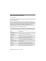
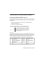
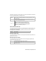
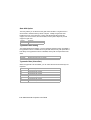
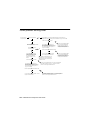
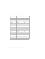
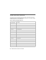
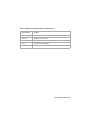
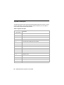
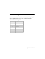
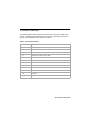
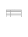
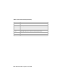
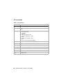
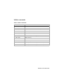
Modem response codes
The following table lists the basic codes that the modem sends to your computer in
response to the commands you type. They are called response codes.
Table 5: Basic Response codes
Digit code
Word code
Meaning
0
OK
Command was carried out without error
1
Connect
Connected at 300 bits per second (bps)
2
Ring
Ringing signal detected
3
No carrier
Carrier is lost or not heard
4
Error
Error in the command line
Invalid command
Command line exceeds buffer
Invalid character format
6
No dial tone
No dial tone during the time-out period
7
Busy
The line being called is busy
8
No answer
The line being called did not answer within the time-out
period
11
Connect xxxx
Connected at 2400 bps
24
Delayed
Dialing delayed
32
Blacklisted
Number is blacklisted
33
Fax
Fax connection
35
Data
Data connection
+F4
+FC error
Fax error
B-12 IBM Personal Computer User Guide
S registers
S registers are information storage areas inside the modem. The AT command set
uses the S registers to configure modem options. Some S registers have default
settings. For normal modem operations, the default settings are usually adequate.
However, special circumstances may require you to change some defaults. To
change or read the value of an S register, begin the command with the letters AT.
To read the value of an S register:
• Use the ATS? command (=register number 0-28).
For example, to read the value of S register 0, type ATS0? and press Enter.
To change the value of an S register:
• Use the ATS= command (=register number 0-28, =the new value you want
to assign).
For example, to change the value of S register 0 to 20 rings, type ATS0=20 and
press Enter.
Modem information B-13
The following table lists the S Registers summary.
Table 6: S registers
Register
Function
Range/units
Default
S0
Auto-answer ring
0-255 /rings
0
S1
Ring counter
0-255 /rings
0
S2
Escape code character
0-255 /ASCII
43
S3
Carriage return character
0-127 /ASCII
13
S4
Line feed character
0-127 /ASCII
10
S5
Backspace character
0-32 /ASCII
8
S6
Dial tone wait time
2-255 /seconds
2
S7
Remote carrier wait time
1-255 /seconds
50
S8
Comma pause time
0-255 /seconds
2
S10
Carrier loss time
1-255 /10ths of a second
14
S11
Touch-tone dialing speed
50-255 /milliseconds
95
S12
Escape character detect time
0-255 /50ths of a second
50
S29
Flash dial modifier time
0-255 /10 milliseconds
70
B-14 IBM Personal Computer User Guide
Appendix C. Monitor terminology
As you read the documentation that came with your monitor and the monitor
information provided in this chapter, you might find a few technical terms. If you
change your monitor settings, refer to the following table to understand some of the
terms used to describe monitor characteristics.
Table 1: Monitor terms and definitions
Term
Definition
display mode
A resolution setting associated with a vertical frequency
setting (and sometimes a color setting). For example, 640x480
at 75 Hz, 256 colors.
horizontal frequency
Rate (in kilohertz [kHz]) at which each line on the screen is
drawn.
interlaced
Method of producing an image by drawing only alternating
lines until the entire image is completed.
noninterlaced
Method of producing an image by drawing each line, one after
the other, until the entire image is completed. This method
produces less flicker than the interlaced method.
pel (or pixel)
A picture element. A small rectangle or portion of an image
that together with other pels make up the entire image.
resolution
The number of pels required to display an image horizontally
and vertically. For example, 640x480 means 640 pels
horizontally and 480 pels vertically.
SVGA
Super video graphics array. A video standard that provides
some of the higher text and graphics resolutions.
vertical frequency/
refresh rate
Rate (in hertz [Hz]) at which the entire image is drawn on the
screen. Also called “refresh rate.”
Monitor terminology C-1
C-2
IBM Personal Computer User Guide
Appendix D. Warranty
Note:
The following warranty applies only to machine types
2196 and 2197. For other machine types, refer to the
warranty that was provided with the computer.
Warranty statements
The warranty statements consist of two parts: Part 1 and Part 2. Part 1 varies by
country. Part 2 is the same for both statements. Be sure to read both the Part 1 that
applies to your country and Part 2.
• United States, Puerto Rico, and Canada (Z125-4753-05 11/97) (Part 1 General Terms on page D-2)
• Worldwide except Canada, Puerto Rico, Turkey, and United States (Z1255697-01 11/97) (Part 1 - General Terms on page D-6)
• Worldwide Country-Unique Terms (Part 2 - Country-Unique Terms on page
D-6)
Warranty D-1
IBM Statement of Limited Warranty for United States,
Puerto Rico, and Canada (Part 1 - General Terms)
This Statement of Limited Warranty includes Part 1 - General Terms and Part 2 Country-Unique Terms. The terms of Part 2 may replace or modify those of Part
1. The warranties provided by IBM in this Statement of Limited Warranty apply only
to Machines you purchase for your use, and not for resale, from IBM or your reseller.
The term “Machine” means an IBM machine, its features, conversions, upgrades,
elements, or accessories, or any combination of them. The term “Machine” does not
include any software programs, whether pre-loaded with the Machine, installed
subsequently or otherwise. Unless IBM specifies otherwise, the following warranties
apply only in the country where you acquire the Machine. Nothing in this Statement
of Warranty affects any statutory rights of consumers that cannot be waived or
limited by contract. If you have any questions, contact IBM or your reseller.
IBM Personal Computer machine
type 2196 and 2197
Warranty Period*: Parts: One (1) Year;
Labor: One (1) Year
Machine:
*Contact your place of purchase for warranty
service information. Some IBM Machines are
eligible for On-site warranty service depending on
the country where service is performed.
The IBM warranty for Machines. IBM warrants that each Machine 1) is free from
defects in materials and workmanship and 2) conforms to IBM’s Official Published
Specifications. The warranty period for a Machine is a specified, fixed period
commencing on its Date of Installation. The date on your sales receipt is the Date of
Installation, unless IBM or your reseller informs you otherwise.
During the warranty period IBM or your reseller, if approved by IBM to provide
warranty service, will provide repair and exchange service for the Machine, without
charge, under the type of service designated for the Machine and will manage and
install engineering changes that apply to the Machine.
If a Machine does not function as warranted during the warranty period, and IBM or
your reseller are unable to either 1) make it do so or 2) replace it with one that is at
least functionality equivalent, you may return it to your place of purchase and your
money will be refunded. The replacement may not be new, but will be in good
working order.
D-2
IBM Personal Computer User Guide
Extent of warranty. The warranty does not cover the repair or exchange of a
Machine resulting from misuse, accident, modification, unsuitable physical or
operating environment, improper maintenance by you, or failure caused by a
product for which IBM is not responsible. The warranty is voided by removal or
alteration of Machine or parts identification labels.
THESE WARRANTIES ARE EXCLUSIVE WARRANTIES AND REPLACE ALL
OTHER WARRANTIES OR CONDITIONS, EXPRESS OR IMPLIED, INCLUDING,
BUT NOT LIMITED TO, THE IMPLIED WARRANTIES OR CONDITIONS OR
MERCHANTIBILITY AND FITNESS FOR A PARTICULAR PURPOSE. THESE
WARRANTIES GIVE YOU SPECIFIC LEGAL RIGHTS AND YOU MAY ALSO HAVE
OTHER RIGHTS WHICH VARY FROM JURISDICTION TO JURISDICTION. SOME
JURISDICTIONS DO NOT ALLOW THE EXCLUSION OR LIMITATION OF
EXPRESS OR IMPLIED WARRANTIES, SO THE ABOVE EXCLUSION OR
LIMITATION MAY NOT APPLY TO YOU. IN THAT EVENT, SUCH WARRANTIES
ARE LIMITED IN DURATION TO THE WARRANTY PERIOD. NO WARRANTIES
APPLY AFTER THAT PERIOD.
Items not covered by warranty. IBM does not warrant uninterrupted or error-free
operation of a Machine.
Unless specified otherwise, IBM provides non-IBM machines WITHOUT
WARRANTIES OF ANY KIND.
Any technical or other support provided for a Machine under warranty, such as
assistance via telephone with “how-to” questions and those regarding Machine setup and installation, will be provided WITHOUT WARRANTIES OF ANY KIND.
Warranty service. To obtain warranty service for the Machine, contact your reseller
or IBM. In the United States, call IBM at 1-919-517-2800. In Canada, call IBM at 1800-565-3344. You may be required to present proof of purchase.
IBM or your reseller provides certain types of repair and exchange service, either at
your location or at a service center, to keep Machines in, or restore them to,
conformance with their Specifications. IBM or your reseller will inform you of the
available types of service for a Machine based on its country of installation. IBM
may repair the failing Machine or exchange it at its discretion.
Warranty D-3
When warranty service involves the exchange of a Machine or part, the item IBM or
your reseller replaces becomes its property and the replacement becomes yours.
You represent that all removed items are genuine and unaltered. The replacement
may not be new, but will be in good working order and at least functionally
equivalent to the item replaced. The replacement assumes the warranty service
status of the replaced item.
Any feature, conversion, or upgrade IBM or your reseller services must be installed
on a Machine which is 1) for certain Machines, the designated, serial-numbered
Machine and 2) at an engineering-change level compatible with the feature,
conversion, or upgrade. Many features, conversions, or upgrades involve the
removal of parts and their return to IBM. A part that replaces a removed part will
assume the warranty service status of the removed part.
Before IBM or your reseller exchanges a Machine or part, you agree to remove all
features, parts, options, alterations, and attachments not under warranty service.
You also agree to
1. ensure that the Machine is free of any legal obligations or restrictions that
prevent its exchange;
2. obtain authorization from the owner to have IBM or your reseller service a
Machine that you do not own; and
3. where applicable, before service is provided
a. follow the problem determination, problem analysis, and service
request procedures that IBM or your reseller provides,
b. secure all programs, data, and funds contained in a Machine
c. provide IBM or your reseller with sufficient, free, and safe access to
your facilities to permit them to fulfil their obligations, and
d. inform IBM or your reseller of changes in a Machine’s location.
IBM is responsible for loss of, or damage to, your Machine while it is 1) in IBM’s
possession or 2) in transit in those cases where IBM is responsible for the
transportation charges.
D-4
IBM Personal Computer User Guide
Neither IBM nor your reseller is responsible for any of your confidential, proprietary
or personal information contained in a Machine which you return to IBM or your
reseller for any reason. You should remove all such information from the Machine
prior to its return.
Production status. Each IBM Machine is manufactured from new parts, or new
and used parts. In some cases, the Machine may not be new and may have been
previously installed. Regardless of the Machine’s production status, IBM’s
appropriate warranty terms apply.
Limitation of liability. Circumstances may arise where, because of a default on
IBM’s part of the liability, you are entitled to recover damages from IBM. In each
such instance, regardless of the basis on which you are entitled to claim damages
from IBM (including fundamental breach, negligence, misrepresentation, or other
contract or tort claim), IBM is liable for no more than
1. damages for bodily injury (including death) and damage to real property and
tangible personal property; and
2. the amount of any other actual direct damages, up to the greater of U.S.
$100,000 (or equivalent in local currency) or the charges (if recurring, 12
months’ charges apply) for the Machine that is the subject of the claim.
This limit also applies to IBM’s suppliers and your reseller. It is the maximum
for which IBM, its suppliers, and your reseller are collectively responsible.
UNDER NO CIRCUMSTANCES IS IBM LIABLE FOR ANY OF THE FOLLOWING:
1) THIRD-PARTY CLAIM AGAINST YOU FOR DAMAGES (OTHER THAN THOSE
UNDER THE FIRST ITEM LISTED ABOVE); 2) LOSS OF, OR DAMAGE TO, YOUR
RECORDS OR DATA; 3) SPECIAL, INCIDENTAL, OR INDIRECT DAMAGES OR
FOR ANY ECONOMIC CONSEQUENTIAL DAMAGES (INCLUDING LOST
PROFITS OR SAVINGS), EVEN IF IBM, ITS SUPPLIERS OR YOUR RESELLER IS
INFORMED OF THEIR POSSIBILITY. SOME JURISDICTIONS DO NOT ALLOW
THE EXCLUSION OR LIMITATION OF INCIDENTAL OR CONSEQUENTIAL
DAMAGES, SO THE ABOVE LIMITATION OR EXCLUSION MAY NOT APPLY TO
YOU.
Warranty D-5
IBM Statement of Warranty Worldwide except Canada,
Puerto Rico, Turkey, United States (Part 1- General Terms)
This Statement of Warranty includes Part 1 - General Terms and Part 2 - CountryUnique Terms. The terms of Part 2 may replace or modify those of Part 1. The
warranties provided by IBM in this Statement of Warranty apply only to Machines
you purchase for your use, and not for resale, from IBM or your reseller. The term
“Machine” means an IBM machine, its features, conversions, upgrades, elements or
accessories, or any combination of them. The term “Machine” does not include any
software programs, whether pre-loaded with the Machine, installed subsequently or
otherwise. Unless IBM specifies otherwise, the following warranties apply only in the
country where you acquire the Machine. Nothing in this Statement of Warranty
affects any statutory rights of consumers that cannot be waived or limited by
contract. If you have any questions, contact IBM or your reseller.
IBM Personal Computer machine
type 2196 and 2197
Warranty Period*: Parts: One (1) Year;
Labor: One (1) Year
Machine:
*Contact your place of purchase for warranty
service information. Some IBM Machines are
eligible for On-site warranty service depending on
the country where service is performed.
The IBM warranty for Machines. IBM warrants that each Machine 1) is free from
defects in materials and workmanship and 2) conforms to IBM’s Official Published
Specifications. The warranty period for a Machine is a specified, fixed period
commencing on its Date of Installation. The date on your sales receipt is the Date of
Installation, unless IBM or your reseller informs you otherwise.
During the warranty period IBM or your reseller, if approved by IBM to provide
warranty service, will provide repair and exchange service for the Machine, without
charge, under the type of service designated for the Machine and will manage and
install engineering changes that apply to the Machine.
D-6
IBM Personal Computer User Guide
If a Machine does not function as warranted during the warranty period, and IBM or
your reseller are unable to either 1) make it do so or 2) replace it with one that is at
least functionality equivalent, you may return it to your place of purchase and your
money will be refunded. The replacement may not be new, but will be in good
working order.
Extent of warranty. The warranty does not cover the repair or exchange of a
Machine resulting from misuse, accident, modification, unsuitable physical or
operating environment, improper maintenance by you, or failure caused by a
product for which IBM is not responsible. The warranty is voided by removal or
alteration of Machine or parts identification labels.
THESE WARRANTIES ARE EXCLUSIVE WARRANTIES AND REPLACE ALL
OTHER WARRANTIES OR CONDITIONS, EXPRESS OR IMPLIED, INCLUDING,
BUT NOT LIMITED TO, THE IMPLIED WARRANTIES OR CONDITIONS OR
MERCHANTIBILITY AND FITNESS FOR A PARTICULAR PURPOSE. THESE
WARRANTIES GIVE YOU SPECIFIC LEGAL RIGHTS AND YOU MAY ALSO HAVE
OTHER RIGHTS WHICH VARY FROM JURISDICTION TO JURISDICTION. SOME
JURISDICTIONS DO NOT ALLOW THE EXCLUSION OR LIMITATION OF
EXPRESS OR IMPLIED WARRANTIES, SO THE ABOVE EXCLUSION OR
LIMITATION MAY NOT APPLY TO YOU. IN THAT EVENT, SUCH WARRANTIES
ARE LIMITED IN DURATION TO THE WARRANTY PERIOD. NO WARRANTIES
APPLY AFTER THAT PERIOD.
Items not covered by warranty. IBM does not warrant uninterrupted or error-free
operation of a Machine.
Unless specified otherwise, IBM provides non-IBM machines WITHOUT
WARRANTIES OF ANY KIND.
Any technical or other support provided for a Machine under warranty, such as
assistance via telephone with “how-to” questions and those regarding Machine setup and installation, will be provided WITHOUT WARRANTIES OF ANY KIND.
Warranty service. To obtain warranty service for the Machine, contact your reseller
or IBM. You may be required to present proof of purchase.
IBM or your reseller provides certain types of repair and exchange service, either at
your location or at a service center, to keep Machines in, or restore them to,
conformance with their Specifications. IBM or your reseller will inform you of the
available types of service for a Machine based on its country of installation. IBM
may repair the failing Machine or exchange it at its discretion.
Warranty D-7
When warranty service involves the exchange of a Machine or part, the item IBM or
your reseller replaces becomes its property and the replacement becomes yours.
You represent that all removed items are genuine and unaltered. The replacement
may not be new, but will be in good working order and at least functionally
equivalent to the item replaced. The replacement assumes the warranty service
status of the replaced item.
Any feature, conversion, or upgrade IBM or your reseller services must be installed
on a Machine which is 1) for certain Machines, the designated, serial-numbered
Machine and 2) at an engineering-change level compatible with the feature,
conversion, or upgrade. Many features, conversions, or upgrades involve the
removal of parts and their return to IBM. A part that replaces a removed part will
assume the warranty service status of the removed part.
Before IBM or your reseller exchanges a Machine or part, you agree to remove all
features, parts, options, alterations, and attachments not under warranty service.
You also agree to
1. ensure that the Machine is free of any legal obligations or restrictions that
prevent its exchange;
2. obtain authorization from the owner to have IBM or your reseller service a
Machine that you do not own; and
3. where applicable, before service is provided
a. follow the problem determination, problem analysis, and service
request procedures that IBM or your reseller provides,
b. secure all programs, data, and funds contained in a Machine
c. provide IBM or your reseller with sufficient, free, and safe access to
your facilities to permit them to fulfil their obligations, and
d. inform IBM or your reseller of changes in a Machine’s location.
IBM is responsible for loss of, or damage to, your Machine while it is 1) in IBM’s
possession or 2) in transit in those cases where IBM is responsible for the
transportation charges.
D-8
IBM Personal Computer User Guide
Neither IBM nor your reseller is responsible for any of your confidential, proprietary
or personal information contained in a Machine which you return to IBM or your
reseller for any reason. You should remove all such information from the Machine
prior to its return.
Production status. Each IBM Machine is manufactured from new parts, or new
and used parts. In some cases, the Machine may not be new and may have been
previously installed. Regardless of the Machine’s production status, IBM’s
appropriate warranty terms apply.
Limitation of liability. Circumstances may arise where, because of a default on
IBM’s part of the liability, you are entitled to recover damages from IBM. In each
such instance, regardless of the basis on which you are entitled to claim damages
from IBM (including fundamental breach, negligence, misrepresentation, or other
contract or tort claim), IBM is liable for no more than
1. damages for bodily injury (including death) and damage to real property and
tangible personal property; and
2. the amount of any other actual direct damages, up to the greater of U.S.
$100,000 (or equivalent in local currency) or the charges (if recurring, 12
months’ charges apply) for the Machine that is the subject of the claim.
This limit also applies to IBM’s suppliers and your reseller. It is the maximum
for which IBM, its suppliers, and your reseller are collectively responsible.
UNDER NO CIRCUMSTANCES IS IBM LIABLE FOR ANY OF THE FOLLOWING:
1) THIRD-PARTY CLAIM AGAINST YOU FOR DAMAGES (OTHER THAN THOSE
UNDER THE FIRST ITEM LISTED ABOVE); 2) LOSS OF, OR DAMAGE TO, YOUR
RECORDS OR DATA; 3) SPECIAL, INCIDENTAL, OR INDIRECT DAMAGES OR
FOR ANY ECONOMIC CONSEQUENTIAL DAMAGES (INCLUDING LOST
PROFITS OR SAVINGS), EVEN IF IBM, ITS SUPPLIERS OR YOUR RESELLER IS
INFORMED OF THEIR POSSIBILITY. SOME JURISDICTIONS DO NOT ALLOW
THE EXCLUSION OR LIMITATION OF INCIDENTAL OR CONSEQUENTIAL
DAMAGES, SO THE ABOVE LIMITATION OR EXCLUSION MAY NOT APPLY TO
YOU.
Warranty D-9
Part 2 - Country-Unique Terms
ASIA PACIFIC
AUSTRALIA: The IBM warranty for Machines. The following paragraph is added
to this Section:
The warranties specifies in this Section are in addition to any rights you may have
under the Trade Practices Act 1974 or other legislation and are only limited to the
extent permitted by the applicable legislation.
Extent of warranty. The following replaces the first and second sentences of this
Section:
The warranty does not cover the repair or exchange of a Machine resulting from
misuse, accident, modification, unsuitable physical or operating environment,
operation in other than the Specified Operating Environment, improper maintenance
by you, or failure caused by a product for which IBM is not responsible.
Limitation of liability. The following is added to this Section:
Where IBM is in breach of a condition or warranty implied by the Trade Practices Act
1974, IBM’s liability is limited to the repair or replacement of the goods or the supply
of equivalent goods. Where that condition or warranty relates to right to sell, quiet
possession or clear title, or the goods are of a kind ordinarily acquired for personal,
domestic or household use or consumption, then none of the limitations in this
paragraph apply.
PEOPLE’S REPUBLIC OF CHINA: Governing Law. The following is added to this
Statement:
The laws of the State of New York govern this Statement.
INDIA: Limitation of liability. The following replaces items 1 and 2 of this Section:
1. liability for bodily injury (including death) or damage to real property and
tangible personal property will be limited to that caused by IBM’s negligence;
2. as to any other actual damage arising in any situation involving
nonperformance by IBM pursuant to, or in any way related to the subject of
this Statement of Warranty, IBM’s liability will be limited to the charge paid by
you for the individual Machine that is subject of the claim.
D-10 IBM Personal Computer User Guide
NEW ZEALAND: The IBM warranty for Machines. The following paragraph is
added to this Section:
The warranties specified in this Section are in addition to any rights you may have
under the Consumer Guarantees Act 1993 or other legislation which cannot be
excluded or limited. The Consumer Guarantees Act 1993 will not apply in respect of
any goods which IBM provides, if you require the goods for the purposes of a
business as defined in that Act.
Limitation of liability. The following is added to this Section:
Where Machines are not acquired for the purposes of a business as defined in the
Consumer Guarantees Act 1993, the limitations in this Section are subject to the
limitations in that Act.
EUROPE, MIDDLE EAST, AFRICA (EMEA)
The following terms apply to all EMEA countries. The terms of this Statement of
Warranty apply to Machines purchased from an IBM reseller. If you purchased this
machine from IBM, the terms and conditions of the applicable IBM agreement
prevail over this warranty statement.
Warranty service. If you purchased an IBM Machine in Austria, Belgium, Denmark,
Estonia, Finland, France, Germany, Greece, Iceland, Ireland, Italy, Latvia, Lithuania,
Luxembourg, Netherlands, Norway, Portugal, Spain, Sweden, Switzerland or United
Kingdom, you may obtain warranty service for that Machine in any of those
countries from either (1) an IBM reseller approved to perform warranty service or (2)
from IBM.
If you purchased an IBM Personal Computer Machine in Albania, Armenia, Belarus,
Bosnia and Herzegovina, Bulgaria, Croatia, Czech Republic, Georgia, Hungary,
Kazakhstan, Kirghizia, Federal Republic of Yugoslavia, Former Yugoslav Republic of
Macedonia (FYROM), Moldova, Poland, Romania, Russia, Slovak Republic,
Slovenia, or Ukraine, you may obtain warranty service for that Machine in any of
those countries from either (1) an IBM reseller approved to perform warranty service
or (2) from IBM.
The applicable laws, Country-unique terms and competent court for this Statement
are those of the country in which the warranty service is being provided. However,
the laws of Austria govern this Statement if the warranty service is provided in
Albania, Armenia, Belarus, Bosnia and Herzegovina, Bulgaria, Croatia, Czech
Republic, Federal Republic of Yugoslavia, Georgia, Hungary, Kazakhstan, Kirghizia,
Former Yugoslav Republic of Macedonia (FYROM), Moldova, Poland, Romania,
Russia, Slovak Republic, Slovenia, and Ukraine.
Warranty D-11
The following terms apply to the country specified:
EGYPT: Limitation of liability. The following replaces item 2 in this Section:
2. as to any other actual direct damages, IBM's liability will be limited to the total
amount you paid for the Machine that is the subject of the claim.
Applicability of suppliers and resellers (unchanged).
FRANCE: Limitation of liability. The following replaces the second sentence of
the first paragraph of this Section:
In such instances, regardless of the basis on which you are entitled to claim
damages from IBM, IBM is liable for no more than: (items 1 and 2 unchanged).
GERMANY: The IBM warranty for Machines. The following replaces the first
sentence of the first paragraph of this Section:
The warranty for an IBM Machine covers the functionality of the Machine for its
normal use and the Machine's conformity to its Specifications.
The following paragraphs are added to this Section:
The minimum warranty period for Machines is six months.
In case IBM or your reseller are unable to repair an IBM Machine, you can
alternatively ask for a partial refund as far as justified by the reduced value of the
unrepaired Machine or ask for a cancellation of the respective agreement for such
Machine and get your money refunded.
Extent of warranty . The second paragraph does not apply. Warranty service.
The following is added to this Section:
During the warranty period, transportation for delivery of the failing Machine to IBM
will be at IBM's expense.
Production status. The following paragraph replaces this Section:
Each Machine is newly manufactured. It may incorporate in addition to new parts,
re-used parts as well.
Limitation of liability. The following is added to this Section:
The limitations and exclusions specified in the Statement of Warranty will not apply
to damages caused by IBM with fraud or gross negligence and for express warranty.
In item 2, replace “U.S. $100,000” with “1.000.000 DEM.”
D-12 IBM Personal Computer User Guide
The following sentence is added to the end of the first paragraph of item 2:
IBM's liability under this item is limited to the violation of essential contractual terms
in cases of ordinary negligence.
IRELAND: Extent of warranty. The following is added to this Section:
Except as expressly provided in these terms and conditions, all statutory conditions,
including all warranties implied, but without prejudice to the generality of the
foregoing all warranties implied by the Sale of Goods Act 1893 or the Sale of Goods
and Supply of Services Act 1980 are hereby excluded.
Limitation of liability. The following replaces items one and two of the first paragraph of this Section:
1. death or personal injury or physical damage to your real property solely
caused by IBM's negligence; and
2. the amount of any other actual direct damages, up to the greater of Irish
Pounds 75,000 or 125 percent of the charges (if recurring, the 12 months'
charges apply) for the Machine that is the subject of the claim or which
otherwise gives rise to the claim.
Applicability of suppliers and resellers (unchanged).
The following paragraph is added at the end of this Section:
IBM's entire liability and your sole remedy, whether in contract or in tort, in respect of
any default shall be limited to damages.
ITALY: Limitation of liability. The following replaces the second sentence in the
first paragraph:
In each such instance unless otherwise provided by mandatory law, IBM is liable for
no more than: (item 1 unchanged) 2)as to any other actual damage arising in all
situations involving nonperformance by IBM pursuant to, or in any way related to the
subject matter of this Statement of Warranty, IBM's liability, will be limited to the total
amount you paid for the Machine that is the subject of the claim.
Applicability of suppliers and resellers (unchanged).
The following replaces the second paragraph of this Section:
Unless otherwise provided by mandatory law, IBM and your reseller are not liable for
any of the following: (items 1 and 2 unchanged) 3) indirect damages, even if IBM or
your reseller is informed of their possibility.
Warranty D-13
SOUTH AFRICA, NAMIBIA, BOTSWANA, LESOTHO AND SWAZILAND:
Limitation of liability. The following is added to this Section:
IBM's entire liability to you for actual damages arising in all situations involving
nonperformance by IBM in respect of the subject matter of this Statement of
Warranty will be limited to the charge paid by you for the individual Machine that is
the subject of your claim from IBM.
TURKIYE: Production status. The following replaces this Section: IBM fulfils
customer orders for IBM Machines as newly manufactured in accordance with IBM's
production standards.
UNITED KINGDOM: Limitation of liability. The following replaces items 1 an 2 of
the first paragraph of this Section:
1. death or personal injury or physical damage to your real property solely
caused by IBM's negligence;
2. the amount of any other actual direct damages or loss, up to the greater of
Pounds Sterling 150,000 or 125 percent of the charges (if recurring, the 12
months' charges apply) for the Machine that is the subject of the claim or
which otherwise gives rise to the claim.
The following item is added to this paragraph:
3. breach of IBM's obligations implied by Section 12 of the Sale of Goods Act
1979 or Section 2 of the Supply of Goods and Services Act 1982.
Applicability of suppliers and resellers (unchanged).
The following is added to the end of this Section:
IBM's entire liability and your sole remedy, whether in contract or in tort, in respect of
any default will be limited to damages.
NORTH AMERICA
CANADA: Warranty service. The following is added to this Section:
To obtain warranty service from IBM, call 1-800-565-3344.
UNITED STATES OF AMERICA: Warranty service. The following is added to this
Section:
To obtain warranty service from IBM, call 1-919-517-2800.
D-14 IBM Personal Computer User Guide
Index
A
adapter cards
PCI 7-7
removing 8-5
ANSI 7-7
error codes and messages 10-17
F
font size 4-4
H
B
battery
replacing 9-10
safety information xvi
book
organization 1-1
C
Call Waiting 4-9
Can’t read information on diskette or CD
10-8
CD-ROM drive
connectors 8-6
color palette 4-4
communications
setting up 4-8
configuration utilities 6-20
Configuration/Setup Utility, See Setup
conflicts 7-2
D
disk drives 6-12, 7-7
adding and removing 8-6
connectors on the system board 8-6
signal cables 8-6
diskette drive
connector 8-6
DMA channels A-7
E
electronic support
Internet 2-4
hard disk
connectors 8-6
hardware changes 7-1, 7-3
recording 7-3
hardware problems 10-7
audio CD does not play when inserted
10-8
can’t enter password 10-8
can’t format diskette 10-9
can’t write to diskette 10-9
computer shuts down without warning
10-7
error code and message appears 107
insert diskette picture appears 10-11
keyboard doesn’t work 10-9
modem/communications error 10-11
mouse doesn’t work 10-10
printer error 10-12
HelpWare, See IBM HelpWare
I
I/O addresses A-4
IBM HelpWare 2-1
30 day "Up and Running" support 2-5
additional support 2-6
electronic support 2-4
hardware warranty service 2-6
software technical support 2-6
IDE
connector 1 8-7
connector 2 8-7
Internet 4-10
Index I-1
connecting through the IBM Global
Network 4-10
connecting through the Internet Setup
Wizard 4-11
connecting through The Microsoft
Network 4-10
IRQs A-6
M
memory map A-1, A-3
memory modules, see DIMMs
installing 4-9
memory modules, see DIMMs
removing 4-10
modem
connecting to the telephone network
4-8
modem card
configurations 6-2
modems B-1
auto-answer feature B-3
monitor
changing refresh rates 4-4
controlling settings 4-2
display mode C-1
display properties 4-3
selecting 4-4, 4-5
display settings 4-3
horizontal frequency C-1
maximizing performance 4-2
power saver feature 4-3
resolution C-1
settings 4-3
vertical frequency C-1
O
online services
CompuServe 2-5
Prodigy 2-5
other publications
online documentation 2-4
Setup Poster 1-4
P
power management
monitor standby 5-6
software shutdown 5-2
system suspend 5-3
printer
emulation mode 4-7
printer driver 4-7
printing 4-7
problem solving
hardware problems 10-7
nothing displayed on the monitor 104, 10-5
simple fixes 10-2
software problems 10-13
Q
quick help
telephone 2-1
quick problem solving chart 10-6
S
safety information
grounding your computer xiii
protecting against electrical shock xiii
self-help
online documentation 2-2
printed documentation 2-2
software 2-3
serial port addresses A-8
Setup
default settings
loading 6-7
entering 46exiting 6-8
main menu 6-5
menu information 6-2
moving through menus 6-5
parameters
aborting setting changes 6-8
changing settings 6-7
product data
I-2 IBM Personal Computer User Guide
viewing 6-6
system information
viewing 6-6
signal cables
connecting 8-9
connecting IDE/ATA 8-7
software
diagnostics 2-3
IBM Update Connector 2-3
software problems
computer doesn’t go to standby 10-13
speaker
adjusting volume 4-6
system board
parts 9-5
parts descriptions 9-3, 9-6
system interrupts A-6
system resources 7-2
conflicts 7-4
system unit
opening 7-5
taking precautions 7-5
parts 7-7
parts descriptions 7-7
removing the cover 7-6, 7-7
T
telephone
Call Waiting feature B-4
telephone network 4-8
V
volume
controlling 4-6
W
Windows 98 Device Manager 7-4
Index I-3
Index I-4