1
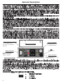
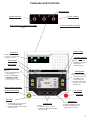
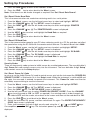
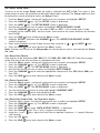
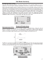
M
S1-5010
Diagnostic Insulation Tester
User Guide
G
SAFETY WARNINGS
•
Safety Warnings and Testing Precautions must be read and understood before the
instrument is used. They must be observed during use
•
The circuit under test must be switched off, de-energised and isolated before test
connections are made.
•
The test terminal panel and side recess panel must be kept in a dry, clean condition.
•
Circuits must be discharged before disconnecting the test leads - Capacitive loads
can be lethal. See ‘Testing Precautions’.
•
Circuit connections must not be touched during a test.
•
In certain circumstances, break-down of the circuit under test may cause the
instrument to terminate the test in an uncontrolled manner, possibly causing a loss of
display and warning indications while the circuit remains energised. In this event, it is
important that the circuit is discharged and the instrument is turned off, before
touching any connections.
• Replacement fuses must be of the correct type and rating.
• The instrument should not be used if any part of it is damaged.
• Refer to ‘Testing Precautions’ for further explanations and precautions.
NOTE
THE INSTRUMENT MUST ONLY BE USED BY SUITABLY TRAINED AND COMPETENT PERSONS.
Symbols used on the instrument
G
F
c
t
2
Caution: Refer to accompanying notes.
Risk of electric shock.
Equipment complies with relevant EU Directives
Equipment protected throughout by Double Insulation (Class II).
Contents
Safety Warnings
General Description
Features and Controls
Battery or Mains Operation
Mains supply re-charging
12 V supply re-charging
Battery Charging Notes
Setting up procedures
Setup Language
Setup IR, SV and DD Tests
Setup PI Tests
Disable a Test Mode
Enable a Test Mode
Delete Stored Test Results
Set / Reset Date and Time
Set / Reset Printer Baud rate
Set / Reset PC Baud rate
Setup / Reset ‘Power On’ code
Setup / Reset ‘Setup’ code
Set / Reset Date format
Set / Reset Current limit
Set / Reset Data Output Rate
Set / Reset Locking test button
Operation
Testing Precautions
Performing tests - General
Using the Filter
Fault Conditioning (Burn)
Remote Operation
Test Mode Summary
Insulation Resistance Testing
Polarization Index Testing
Dielectric discharge Testing
Step Voltage Testing
Fault Conditioning (Burn)
Data Retrieve
Display stored Test results
Download stored Test results to a printer
Downloading Test results to a PC
Application Notes
Preventive Maintenance
Insulation testing concepts
Test Techniques
Using the Guard terminal
Measurements above 100 GΩ
Circuit block diagram
Calibration Check
Appendix 1
Specification
Accessories
Repair and Warranty
2
4
5
6
6
6
6
7
7
7
7
8
8
9
9
10
10
10
11
11
11
11
12
13
13
14
15
16
16
17
17
17
18
18
19
20
20
20
20
21
21
22
23
23
23
24
24
25
26
27
28
3
General Description
HV ‘On’ indicator connection
5 V logic signa output.
(To connect an external HV
indicator)
RS232 connection
Download ‘Real time’ or
‘Batch’ results to PC.
Remote operation.
Battery Charge Indicator
4
12 V d.c. connection
Side recess Panel
Plug in supply of 10 - 15 V
to charge the battery
Fuse
200 mA - 250 V
Mains connection
Plug in supply of 95 - 265 V a.c.
to charge the battery.
Features and Controls
Guard Terminal
Positive Terminal
Negative Terminal
To insert and lock in shrouded test plugs
To release shrouded test plugs
Push in
turn a quarter turn and pull out
Voltage setting
HV Warning
Flashes when a test is in
progress or a hazardous
voltage is present.
Right Hand Cursor
keys
Press to select and
highlight the required
voltage before
commencing test.
Date and time
Mode setting
Left Hand Cursor keys
Press to:-
VARI position
Gives the option to:i) Select a non standard
voltage between 25 V
and 5000 V before
commencing test.
ii) Continuously vary the
voltage in 25 V steps
during a test.
i) Select and highlight the
required mode.
ii) Select test Results /
& Bargraph / Graph
in Enhanced mode.
(when test has run ≥ 1 minute)
Battery Capacity Indicator
Power On / Off Switch
Test duration
Press to turn On / Off.
Test Button
Filter key
Press to:i) Sequentially select filter times.
(See ‘Using the Filter’)
ii) Initiate the ‘On screen’ display
above the key.
Contrast keys
Press to:i) Adjust the screen contrast.
ii) Initiate the ‘On screen’ display
above the key
Backlight key
Press to:i) Switch backlight On or Off.
ii) Initiate the ‘On screen’
display above the key.
5
Setting Up Procedures
The S1-5010 can be powered by:
• Internal rechargeable battery which provides at least 8 hours of testing.
• Mains input of 95 volts to 280 volts 50/60 Hz.
• 12 - 15 Volts d.c or a.c.
General
The S1-5010 is fitted with a 12 volt, 7 Amp-hour sealed lead-acid battery. The maintenance free
battery will last for at least 5 years if kept charged and not subjected to prolonged high temperatures.
(Occasional exposure to +50° C will do little harm but a continuous temperature >40° may cause
irreparable damage). It is advisable to fully charge the battery before the instrument is put into service
for the first time. Charging is carried out by external a.c. mains supply, or by 12 V d.c. or a.c. supply.
To fully recharge the battery after 8 hours of use takes about 16 hours. The battery capacity display
symbol indicates the state of charge.
Mains supply re-charging
The application of a mains supply of 95 - 265 V a.c., 50 - 60 Hz powers the instrument, and charges
the battery. The S1-5010 will operate on a supply as low as 90 volts, but this will not fully charge the
battery. Charging is automatic as soon as the mains supply is connected to the IEC 320 connector in
the side recess panel. Confirm that the red indicator lamp is illuminated.
12 V supply re-charging
The application of an external 12 - 15 volt d.c or a.c. supply powers the instrument and charges the
battery at the same rate of charge as the mains input. It is possible to connect both mains and a 12
volt input simultaneously, but this will not charge the battery any faster. The socket accepts 12 -15 volt
d.c. (any polarity connection) or 12 - 15 volt a.c. A charging lead fitted with an automotive cigar lighter
plug for charging the battery from a vehicle is available (See ‘Accessories’). Charging is automatic
as soon as the 12 V supply is connected to the 12 V DIN socket. Confirm that the red indicator lamp
is illuminated.
Leave unconnected
Connection
Connection
12 V DIN socket
Caution:- Applying more than 15 V to this socket may overcharge the battery.
Battery Charging Notes
•
Do not leave battery in a totally discharged state. Frequent charging to keep the battery ‘topped
up’ will maximise battery life.
•
When charging the battery indoors, the area should be well ventilated.
•
The battery should only be charged at temperatures in the range 0 °C to 40 °C.
•
No harm will occur to the battery is kept on charge indefinitely.
•
If the instrument is idle for long periods, recharge the battery for at least 24 hours every 6
months (more frequently if the storage temperature is >40 °C).
6
Setting Up Procedures
Note: † If pre-set, the ‘SETUP’ security code input screen will be displayed. Enter the 3 digit security
code using the ‘+’ , ‘-’
and ‘NEXT‘
keys. Press the ‘OK’
key to display the ‘SETUP‘
screen.
Setup Screens
Any changes made to the ‘Setup’ screens will be retained. Memory contents will only be lost in the
unlikely event of a power loss combining a failure of the main and the backup battery. When power is
restored, Setup conditions will revert to the default settings i.e. All tests enabled , all voltages enabled,
First PI value T1 = 1minute, Second value T2 = 10 minutes, Stop time (T3) = 10 minutes, and
enhanced test mode.
Setup Language §
1. From the first ‘Menu’ screen, use the left hand st cursor keys to select and highlight ‘SETUP’.
2. Press the ‘CHANGE’ key. †§ The ‘LANGUAGE SELECTION‘ screen is displayed.
3. Use the left hand cursor keys to select and highlight the required language.
4. Press the ‘YES’ key. The ‘SETUP‘ screen is displayed.
Setup IR, SV and DD Tests
Simple or Enhanced mode can be selected for each type of test (except DD test). ‘SIMPLE’ mode
provides basic test results during, and on completion of a test. ‘ENHANCED’ mode provides basic
test results and a graph plot and a Bargraph as the test progresses. Individual voltage ranges for
each type of test can be switched Off or On as required.
1.
2.
3.
4.
5.
6.
7.
8.
From the ‘Menu’ screen, use the left hand cursor keys to select and highlight ‘SETUP’.
Press the ‘CHANGE’ key. †§ The ‘SETUP‘ screen is displayed.
Use the left hand cursor keys to select and highlight the required test.
Press the ‘CHANGE’ key. The ‘SETUP MODE‘ option screen for the selected test is
displayed.
Press the ‘SIMPLE’ or the ‘ENHANCED’ key as required. The ‘TEST RANGES’ screen is
displayed. Note:- selecting the ‘DISABLE‘ key will disable and remove the test from the
‘Menu’ screen. See ‘Disable a Test’.
Use the left hand cursor keys to individually select and highlight any voltage ranges to be
switched Off or On. Press the ‘On’ or ‘OFF’ key, as appropriate.
On competion, press the ‘END‘ key to return to the ‘SETUP‘ screen.
Press the ‘END‘ key to return to the ‘Menu’ screen.
7
Setting Up Procedures
Example showing the setup of an enhanced SV Test
Setup PI Test
1. From the ‘Menu’ screen, use the left hand cursor keys to select and highlight ‘SETUP‘.
2. Press the ‘CHANGE’ key. †§ The ‘SETUP‘ screen is displayed.
3. Use the left hand cursor keys to select and highlight ‘PI’. Press the ‘CHANGE’ key. The
‘PI TEST SETUP‘ screen is displayed.
4. Press the ‘PI TEST TIMES‘ key. The ‘PI TEST TIMES‘ screen is displayed.
5. Press the ‘NEXT‘ key to highlight and select the First Value, the Second Value or the Stop
Time as required.
6. Using the ‘+’ et ‘-’ keys, adjust the timing as required.
7. Press the ‘OK’ key to return to the ‘PI TEST SETUP‘ screen.
8. Use the left hand cursor keys to select and highlight ‘PI‘. Press the ‘CHANGE’ key. The ‘PI
TEST SETUP‘ screen is displayed.
9. Press the ‘SET PI TEST‘ key. The ‘PI TEST SETUP MODE‘ screen is displayed.
10. Press the ‘SIMPLE’ or the ’ENHANCED‘ key as required ‘TEST RANGES‘ screen is
displayed. Note:- selecting the ‘DISABLE‘ key will disable and remove the IP test from the
‘Menu’ screen. See ‘Disable the Test‘.
11. Use the left hand cursor keys to individually select and highlight any voltage ranges to be
switched Off or On. Press the ‘ON’ or ‘OFF’ key, as appropriate.
12. On completion, press the ‘END‘ key to return to the ‘SETUP’ screen.
13. Press the ‘END‘ key to return to the ‘Menu’ screen.
Disable a Test mode
When a test mode is disabled, it is removed fromthe ‘Menu’ screen.
1. From the ‘Menu’ screen, use the left hand cursor keys to select and highlight ‘SETUP‘.
2. Press the ‘CHANGE’ key. †§ The ‘SETUP‘ screen is displayed.
3. Use the left hand cursor keys to select the test to be disabled.
4. Press the ‘CHANGE’ key. The ‘SETUP MODE‘ screen is displayed.
5. Press the ‘DISABLE‘ key. The ‘SETUP‘ screen is displayed.
6. Press the ‘END‘ key to return to the ‘Menu’ screen.
Alternatively, a test can be disabled by individually setting each test voltage to ‘OFF’.
8
Example showing the disabling of a PI Test
Enable a Test mode
1. From the ‘Menu’ screen, use the left hand cursor keys to select and highlight ‘SETUP‘.
2. Press the ‘CHANGE’ key. †§ The ‘SETUP‘ screen is displayed.
3. Use the left hand cursor keys to select the test (identified as OFF) to be enabled.
4. Press the ‘CHANGE’ key. The ‘SETUP MODE‘ screen is displayed.
5. Press the ‘SIMPLE’ , or the ‘ENHANCED‘ key, as required. The ‘TEST RANGES‘ screen is
displayed.
6. Use the left hand cursor keys to individually select and highlight any voltage ranges to be
switched Off or On. Press the ‘ON’ or ‘OFF’ key, as appropriate.
7. On completion, press the ‘END‘ key to return tothe ‘SETUP‘ screen.
8. Press the ‘END‘ key to return back to the ‘Menu’ screen.
Alternatively, a test can be enabled by individually setting at least one test voltage to ‘ON’.
Example showing the enabling of a DD Test
Delete Stored Test results
1. From the ‘Menu’ screen, use the left hand cursor keys to select and highlight ‘SETUP‘.
2. Press the ‘CHANGE’ key. †§ The ‘SETUP‘ screen is displayed.
3. Use the left hand cursor keys to select and highlight ‘TESTS STORED‘. Press the ‘CHANGE’
key. The ‘DELETE ALL TESTS - CONFIRM‘ screen is displayed.
4. Accept or reject the deletion by pressing the ‘YES‘ or the ’NO‘ key. The ‘SETUP MODE’
screen is displayed.
5. On completion press ‘END’ key to return back to the ‘Menu’ screen.
Set / Reset Date and Time
1. From the ‘Menu’ screen, use the left hand cursor keys to select and highlight ‘SETUP’.
2. Press the ‘CHANGE’ key. †§ The ‘SETUP‘ screen is displayed.
3. Use the left hand cursor keys to select the current Date and Tiime.
4. Press the ‘CHANGE’ key. †§ The ‘SETUP MODE‘. ‘SET CLOCK’ screen is displayed.
5. Press the ‘NEXT‘ key to highlight and select the Time / Date component to be adjusted.
6. Using the ‘+’ and ‘-’ keys, adjust the time / Date as required.
9
Setting Up Procedures
7. Press the ‘END’ key to return to the ‘SETUP‘ screen.
8. Press the ‘END’ key to return back to the ‘Menu’ screen.
Note:- Date format can be also be changed as required. See ‘Set / Reset Date Format’.
Set / Reset Printer Baud Rate
This is the communication rate used when retrieving results to a serial printer.
1. From the ‘Menu’, screen, use the left hand cursor keys to select and highlight ‘SETUP‘.
2. Press the ‘CHANGE’ key. †§ The ‘SETUP‘ screen is displayed.
3. Press the ‘NEXT‘ key. Use the left hand cursor keys to select and highlight ‘PRINTER
BAUD‘.
4. Press the ‘CHANGE’ key. †§ The ‘PRINTER BAUD‘ screen is displayed.
5. Use the ‘NEXT‘ key to select and highlight the Baud Rate as required.
6. Press the ‘END’ key.
7. Press the ‘END’ key to return back to the ‘Menu’ screen.
Set / Reset PC Baud Rate
This is the communication speed to your PC when retrieving results to a PC file and does not affect
the speed when using the S1-5010 with the remote control software. The default Baud rate is 9600.
1.
2.
3.
4.
5.
6.
7.
From the ‘Menu’ screen, use the left hand cursor keys to select and highlight ‘SETUP‘.
Press the ‘CHANGE’ key. †§ The ‘SETUP‘ screen is displayed.
Press the ‘NEXT‘ key. Use the left hand cursor keys to select and highlight ‘PC BAUD‘.
Press the ‘CHANGE’ key. The ‘PC BAUD‘ screen is displayed.
Use the ‘NEXT‘ key to select and highlight the Baud Rate as required.
Press the ‘END‘ key.
Press the ‘END‘ key to return back to the ‘Menu’ screen.
Security Codes
There are two security code systems to inhibit access by unauthorized persons. The user definable 3
digit ‘Power On’ code controls access entry into the instrument. The user definable 3 digit ‘Setup’
code controls access to the Setup displays.
Set / Reset ‘Power On’ Code
to set or re-set the 3 digit ‘Power On’ code to control access enty into the instrument the ‘POWER ON
SECURITY CODE’ is switched to On in the ‘Setup’ mode. When the instrument is switched Off and
On again, the new code is entered, to operate the instrument. This ‘Power On’ code must then be
entered by anyone wishing to use the instrument.
1.
2.
3.
4.
5.
6.
7.
On
From the ‘Menu’, screen, use the left hand cursor keys to select and highlight ‘SETUP‘.
Press the ‘CHANGE’ key. †§ The ‘SETUP‘ screen is displayed.
Press the ‘NEXT‘ key. The ‘SETUP MODE‘ screen is displayed.
Use the left hand cursor keys to select ‘POWER ON SECURITY CODE‘. Press the ‘CHANGE’
key to set the code to ‘ON‘ (or ‘OFF‘ as required). If an existing code is to be changed, set
the code to OFF; exit the screen; return back to the screen and then set the code back to ‘ON‘.
Press the ‘END‘ key to exit back to the ‘Menu’ screen.
Switch the instrument Off, pause, and then switch back On again. The ‘ENTER THE SECURITY
CODE‘ input screen is displayed.
Enter (and remember) the new 3 digit security code using the ‘+’ , ‘-’ and ‘NEXT‘ keys.
completion, press the ‘OK’ key. The instrument powers up and the ‘Menu’ screen is
displayed.
10
Set / Reset ‘Setup’ Code
To set or re-set the 3 digit ‘Setup’ code, the code is switched from OFF to ON. The screen is then
exited and on re-entry, the required user definable 3 digit code is entered. This ‘Setup’ code must then
be entered by anyone wishing to access the Setup screens.
1.
2.
3.
4.
5.
From the ‘Menu’ screen, use the left hand cursor keys to select and highlight ‘SETUP’.
Press the ‘CHANGE’ key. †§ The ‘SETUP’ screen is displayed.
Press the ‘NEXT‘ key. The ‘SETUP MODE‘ screen is displayed.
Use the left hand cursor keys to select and highlight ‘SETUP SECURITY CODE’.
Press the ‘CHANGE’ key to set the code to ‘ON‘ (or ‘OFF‘). If an exisiting code is to be
changed, set the code to ‘OFF‘; exit the screen; return back to the screen and then set the code
back to ‘ON‘.
6. Press the ‘END’ key to exit back to the ‘Menu’ screen.
7. Highlight ‘SETUP‘, and press the ‘CHANGE’ key. The ‘ENTER THE SECURITY CODE’
screen is displayed.
8. Enter (and remember) the new 3 digit security code using the ‘+’ , ‘-’ and ‘NEXT‘ keys.
9. Press the ‘END’ key to return back to the ‘Menu’ screen.
Note:- Persons with access to the Setup mode will also be able to access (and control) the ‘Power
On‘ code.
Set / Reset Date Format
Date format can be selected as DD / MM / YY - YY / MM / DD - MM / DD / YY. Note that changes
to the Date format will only be shown in subsequent test data.
1. From the ‘Menu’ screen, use the left hand cursor keys to select and highlight ‘SETUP’.
2. Press the ‘CHANGE’ key. †§ The ‘SETUP’ screen is displayed.
3. Press the ‘NEXT’ key. The ‘SETUP MODE’ screen is displayed.
4. Use the left hand cursor keys to select and highlight ‘DATE FORMAT’.
5. Press the ‘CHANGE’ key to select the appropriate sequence for Day (DD) Month (MM) and
Year (YY).
6. Press the ‘END’ key to return back to the ‘Menu’ screen.
Set / Reset Current limit
1. From the ‘Menu’ screen, use the left hand cursor keys to select and highlight ‘SETUP’.
2. Press the ‘CHANGE’ key. †§ The ‘SETUP’ screen is displayed.
3. Press the ‘NEXT’ key. The ‘SETUP MODE’ screen is displayed.
4. Use the left hand cursor keys to select and highlight ‘CURRENT LIMIT’.
5. Press the ‘CHANGE’ key to select 2 mA or 5 mA.
6. Press the ‘END’ key to return back to the ‘Menu’ screen.
Set / Reset Data Output Rate - for ‘Real time’ output
1. From the ‘Menu’ screen, use the left hand cursor keys to select and highlight ‘SETUP’.
2. Press the ‘CHANGE’ key. †§ The ‘SETUP’ screen is displayed.
3. Press the ‘NEXT’ key.
4. Press the ‘NEXT’ key again. ‘DATA OUTPUT EVERY...’ is displayed.
5. Press the ‘Change’ key. The ‘+’ and ‘-’ controls are displayed.
6. Using the ‘+’ and ‘-’ keys, adjust the Data Rate as required. Maximum = 1 second, Minimum
= 60 seconds
7. Press the ‘OK’ key.
8. Press the ‘END’ key to return back to the ‘Menu’ screen.
11
Set / Reset Locking Test button
The red Test button defaults to locking, when pushed for more than 1 second. The button can be
set to ‘Locked’ or ‘Unlocked’.
1. From the ‘Menu’ screen, use the left hand cursor keys to select and highlight ‘SETUP’.
2. Press the ‘CHANGE’ key. †§ The ‘SETUP’ screen is displayed.
3. Press the ‘NEXT’ key.
4. Press the ‘NEXT’ key again.
5. Use the left hand cursor keys to select and highlight ‘TEST BUTTON’.
6. Press the ‘Change’ key to select ‘LOCKING’, or ‘NOT LOCKING’, as required.
Note:- If ‘NOT LOCKING’ is selected,‘Fault Conditioning’ - (BURN) mode is not available.
7. Press the ‘OK’ key.
8. Press the ‘END’ key to return back to the ‘Menu’ screen.
12
Operation
Testing Precautions
The circuit under test must be completely de-energized
and isolated before test connections are made
•
•
•
•
•
•
•
•
•
If
The S1-5010 can generate up to 5 mA at 5000 V. Circuit connections must not be touched
when testing.
When turned On, voltage in excess of 5 volts across the + and - terminals will be indicated on the
display.
The voltage indicator and automatic discharge features of the S1-5010 should be regarded as
additional safety features and not a substitute for normal safe working practice.
When carrying out prolonged unattended tests, care should be taken ensure that harm or damage
cannot be caused.
When using the‘BURN’ feature, care must be taken that no harm or damage can be caused.
The test terminal area and side recess panel recess must be kept in a dry, clean condition.
If any part of the instrument is damaged, it should not be used, but returned to the manufacturer
or an approved repair company.
Fuse replacement must be of the correct type and rating. See ‘‘Specification’.
Should the plug on the power cord not be the type for your socket outlets (receptacles), do not
use an adaptor. Use a suitable alternative power cord. Wires in power cords are coloured as
U.S.A.
follows: U.K / International
Earth (Ground
Yellow/Green
Green
Neutral
Blue
White
Phase (Line)
Brown
Black
using a fused plug, a 3 Amp fuse to BS1362 should be fitted.
Working with Capacitive Loads
Charged Circuit Discharge
Capacitive circuits charged to several kV can be lethal.
Circuits must be discharged before handling and connecting the test leads, and
similarly before disconnecting the test leads.
At the end of a test, any external capacitance is discharged automatically and the warning
devices will continue to indicate until the terminals are in a safe condition. While the
instrument design incorporates maximum safety, safe working practice should assume that the
instrument discharge circuit and warning devices could fail, and a shorting link should be
connected across capacitive loads before handling them
*
Automatic discharge must not be relied upon as an alternative to normal safe working
practice.
*
Care must be taken to prevent capacitive circuits becoming disconnected during a test,
leaving the circuit in a charged state.
Dielectric Absorption
Some capacitive items exhibit an effect called Dielectric Absorption. The dielectric can absorb
charge during the test. After the item is discharged, the absorbed charge is released back onto
the capacitive ‘plates’ effectively raising the voltage of the item, possibly to dangerous
levels. Safe working practice dictates that tested items should be firmly shorted out with a
shorting link, after discharge, until required for use
13
Operation
Performing Tests - General
•
Ensure that all test leads are clean and in good condition, and firmly connect them to the
instrument and to the isolated circuit under test.
•
Switch the instrument On by pressing the yellow ‘On / Off’ switch once. The calibration check
runs to check the operation of the measurement system and correct any small calibration errors
which may occur during the life of the instrument.
•
The ‘Menu’ screen is displayed on completion of the calibration check. If necessary, adjust the
contrast setting using the .key.
•
The key allows the back light to be switched On or Off. (Switching the back light off, will
conserve battery power by 10%).
•
Select the required Test mode using the left hand cursor keys.
•
Test time shown in the bottom right hand corner of the display indicates maximum test duration
before it is stopped automatically. (Maximum test duration is 90 minutes). Accept the default test
time or use the right hand cursor keys to select and highlight the time indicator. Press the
‘CHANGE’ key, followed by the ‘+ / -’ keys to set the required time.
•
The required Test Voltage is selected with the right hand cursor keys. For specific types of test,
pre-determined default voltages are set. For instance, the Step Voltage test only offers test
voltage options of 2500 or 5000 volts. The ‘VARI’ position gives the option to select a nonstandard voltage between 25 and 5000 V d.c., or to continuously vary the voltage in 25 V steps
during a test by using the right hand cursor keys.
•
Battery condition indication is given in the bottom left hand corner of the display. If the battery
becomes completely exhausted the instrument will refuse to operate. Recharge the battery as
soon as possible. If the battery is not recharged it could degrade to a state where it will not
recharge.
Note:- Test results and settings are protected by a backup battery so these will not be lost.
•
To start a Test, press the red button for at least one second. Two bleeps are sounded and the
F, flashing test terminal indicator light, and symbols warn that a test is in progress.
•
If Enhanced tests have been selected, after one minute, three types of result screen can be
selected (Results / Bargraph / Graph) using the left hand cursor keys either during, or after a
test.
•
To stop a test at any time, press the red test button. If the red test button is not pressed, the
test will terminate at the end of the set test duration
•
Allow the item to discharge.
•
A test will automatically terminate if:-
14
-
The set test duration is completed.
-
Excessive electrical noise occurs.
-
The circuit insulation under test suffers a complete breakdown.
-
The battery becomes exhausted.
-
The 200 mA Guard fuse ruptures (when the Guard terminal is in use).
-
An internal fault occurs.
-
When the test is terminated the item under test will be automatically discharged.
•
To return to the menu display and start another test, press the ‘Menu’
key.
•
To switch the instrument Off, press the On / Off button once. Auto switch-off operates after 10
minutes inactivity.
•
On completion of a test, the item under test is automatically discharged. The high voltage
warnings continue to operate until the terminal voltage falls to less than 50 volts. If the test has
run for more than one minute, three types of result display can be selected (Results / Bargraph
/ Graph) using the left hand cursor keys.
Using the Filter
If stable readings are being obtained it is not necessary to use the filter. The multi-pole electrical
interference filter system enables measurements to stabilise in a few seconds while rejecting 50Hz
and 60Hz interference currents, up to 4 mA. Under adverse conditions it may be necessary to switch
in additional software filtering. A steady reading will then be obtained at the expense of a longer
settling time.
Filter settings available:
Default-
No Filter.
Fastest settling time. Rejects a.c. interference up to 1 mA.
FILT 3:
Hardware filter. Approximately 3 second settling time. 4 mA a.c. rejection.
FILT 10:
Adds software filter giving moving average over 10 seconds.
FILT 30:
As above, for 30 seconds.
FILT 100:
As above, for 100 seconds.
At the start of a test, the default setting FILT 3 is set. This provides very good interference rejection,
allowing measurements to be made quickly. Pressing the filter
key will sequentially advance filter
settings. To optimise the settling time, toggle the filter key several times to turn the filter Off. Note that
if the filter is turned On again (either manually or automatically) it may cause a transient change in the
reading which can last up to several seconds.
Tip: If a long time constant filter is in use, toggle the filter
required reading faster.
key to re-start the filter and obtain the
Note:- When testing at less than 500 volts, the tolerance to external interference is reduced. This is
because of voltage regulation problems caused by a.c. current flowing into the positive terminal
impedance of about 80 kΩ. Such a condition will be evident by the fact that the terminal voltage will
change from its set value.
Note:- Selecting a new filter time discards all previous readings and begins building up a new average.
The displayed value will move to the most recently acquired result. e.g. If FILT 3 is in operation and
the filter key is pressed once (to select the FILT 30) the most recent unfiltered result is displayed.
This will be followed by the average of two results, three results, four results etc. until it showing the
average of the last 30 results. Note that averaging is performed on measured current (not calculated
resistance). This is the best way to reject incoming a.c. interference but it can produce some unusual
settling characteristics when observing resistance measurements.
15
Operation
Fault Conditioning (Burn)
BURN disables the normal ‘breakdown’ detection and enables the Insulation test voltage to
continue even after breakdown at any weak point of the circuit insulation. This will enable the
location of the failure to be seen or heard.
Note:- The Test Button must be be set to ‘LOCKED’ position to use the BURN mode
Care must be taken that no unintentional harm or damage can be caused
1. Setup the Test Button to the ‘LOCKED’ position. See ‘Set / Reset Locking Test button’.
2. From the ‘Menu’ screen, select’ INSULATION RESISTANCE’ using the left hand cursor keys.
3. Use the right hand cursor keys to select and highlight the time indicator. Press the ‘CHANGE’
key, followed by the ‘+ / -’ keys to set the required time.
4. Set the required Test Voltage with the right hand cursor keys.
5. Press, and hold the red button for at least five seconds. Two bleeps are sounded. To warn that
a test is in progress, BURN is displayed, alternating with
, symbols. The test terminal
indicator light flashes.
6. Test progression is shown by a Bargraph. Using the left hand cursor keys a Results or
Graph result screen can be selected either during, or after a test.
Break-down of the circuit and the related noise interference may cause the instrument terminate
the operation, possibly causing a loss of display while the circuit remains energised. In this
event, it is important that the circuit is discharged before touching any connections. If necessary,
switch the instrument off, and then on again to reset the display.
7. To stop the test at any time, press the red test button. ‘DISCHARGING‘ is displayed, until the
circuit is in a safe condition.
8. To return to the menu display press the ‘Menu’ key.
9. If required, Setup the test button to the ‘NOT LOCKED’ position.
Remote operation
A software package S1-S1 is available for controlling the S1-5010 directly from a PC. You may also
automatically define certain test sequences. See ‘Accessories’.
16
Test Mode Summary
Insulation Resistance Testing
This test mode measures insulation resistance continuously at the selected voltage. The test is
applied for a short but specific duration, immediately after which a reading is taken. Test duration is
typically 30 or 60 seconds and the S1-5010 will allow you to set this duration, and the test will finish
automatically. The reading will not necessarily be the maximum value but if the same duration is used
each test, then the same point on the curve of increasing apparent resistance is being compared. On
installation these readings will be compared to the required minimum specification. Further readings
taken for maintenance purposes must be monitored for any trend that they show. The readings are
subject to variation from temperature and humidity and these factors may require the insulation
reading to be corrected. Information on temperature correction is given in the MEGGER publication
‘A Stitch in Time’. Alternatively, a Polarization Index (PI) test may be used.
Example of IR Graphic display
Polarization Index (PI) Test
Time resistance tests are successive insulation readings at specified times, taking the ratio of
dielectric absorption into account, and are independent of temperature. Good insulation generally
shows an increase in resistance over a 10 minute period. With contaminated insulation, absorption
effects are masked by high leakage currents and the readings are therefore fairly flat.
The PI test is a particular example of the time resistance method, and takes the ratio of the insulation
values at 1 minute (designated T1) and at 10 minutes (designated T2) - this is the Polarization Index.
The PI test also has the advantage of not requiring temperature correction.
Example of PI display
17
Test Mode Summary
The value of PI can often help in the situation where past test record frequency are limited, by giving
a rough guide to condition of insulator. The figures should always be interpreted in the context of the
equipment history and your experience.
PI TEST RESULT
INSULATION CONDITION
<1,0
Unsatisfactory
1,0 to 2,0
Dubious
2,0 to 4,0
Good
>4,0
Very Good
There are two specific conditions to be aware of when interpreting PI test results, particularly if a
history of the equipment is unavailable.
1)
Dry, brittle insulation (e.g. on windings) on can give a high PI but fail under shock conditions.
2)
If multi-layered insulation fails in one of the layers while the others retain high resistances, the
effect on the test current will tend to increase the PI value, masking possible problems from
surface leakage caused by dirt and contamination.
Dielectric Absorption Ratio is the term applied to a Polarization Index at other time intervals using
‘Setup’. Whatever times are set, these will be carried through to the Dielectric Discharge (DD) test
which produces a PI value while it is doing the DD test.
Dielectric Discharge Testing
The Dielectric Discharge (DD) Test is a diagnostic insulation test that allows ageing and deterioration
of insulation to be assessed. The result is dependent on the discharge characteristic, so the internal
condition of the insulation is tested, largely independent of any surface contamination. The charge that
is stored in the insulation material under test, is measured during the discharge phase.
The charge that is stored during the insulation test is automatically discharged at the end of the test
when the discharge resistors are switched across the terminals. The rate of discharge depends only
on the discharge resistors and the amount of stored charge from the insulation.
The capacitive current quickly decays from a high value with a relatively short time constant (a few
seconds). The absorption (or re-absorption during a discharge) current starts from a lower level but
has a much longer time constant (up to several minutes). This is caused by ions and dipoles realigning themselves within the insulation. When an electric field is applied some ions are able to move,
and some dipoles align themselves within the field. These effects reverse themselves slowly when the
test voltage is removed, caused by particles returning to their natural random state.The DD test
measures the discharge currents 1 minute after an insulation test has been completed. At this time
the capacitive current has usually become insignificant compared with the re-absorption current. The
level of re-absorption after this time shows the condition of the insulation material, providing that the
insulation material has been fully charged for full absorption to take place (typically 10 to 30 minutes).
A high re-absorption current shows that the insulation has been contaminated, usually by moisture. A
low current usually shows that the insulation is clean and has not absorbed much moisture.
The dielectric discharge test measures the discharge current 60 seconds after the insulation test is
completed. This is converted to a figure of merit which gives a figure for the quality of the insulation,
independent of the test voltage. This value is temperature dependent so it is important to test at a
reference temperature, or record the value.
The DD value is defined as:
Current flowing after 1 minute (mA)
Test Voltage (V) x Capacitance (μF)
18
=
I 1min
VxC
The maximum DD value that can be measured (assuming the default test voltage of 500 V) is typically
20, if the capacitance of the test sample is 1μF, but decreasing to 2 for a capacitance of 10 μF. If the
maximum value has been exceeded the result will show a ‘>’ symbol in front of the number (e.g.
‘>20’).
DD Test Result (in mA V-1F-1)
>7
>4
2-4
<2
Insulation Condition
Bad
Poor
Questionable
O.K.
Step Voltage Testing
This test is based on the principle that an ideal insulator will produce identical insulation readings at
all voltages, while an insulator which is being over stressed, will show lower insulation values at
higher voltages. The selected voltage (2,5 kV or 5 kV) steps from zero by one fifth of the final value
every minute, for 5 minutes, taking successive measurements until the final voltage value is reached.
Example of Step Voltage Testing display
Fault Conditioning (Burn)
For a normal Insulation resistance test, when a Burn test is not initiated, the voltage will be turned Off
after a breakdown. This reduces the possibility of unintentional damage to the insulation by carbon
tracking, or by arcing. Burn test mode disables the ‘breakdown’ detector and allows the Insulation
resistance test voltage to be continued until it causes burning and insulation breakdown at a weak
point of the circuit. If a Burn test is initiated, the instrument will maintain the high voltage even after a
breakdown is caused, enabling the location of the failure to be seen or heard.
19
Data Retrieve
Results are automatically stored when a test runs for more than one minute. Tests are identified by
date and test number. At each date change, test numbering restarts at 1.The time of the test (24 hour
clock format) is also stored. A maximum of 75 tests can be stored. Attempting to store more than 75
tests will cause the oldest test results to be erased. A warning message will appear before test results
are automatically erased.
Display Stored Test results
1.
From the ‘Menu’ screen, use the left hand cursor st keys to select and highlight ‘RETRIEVE’.
2.
Press the ‘START’ key. The output device list is displayed.
3.
Use the left hand cursor st keys to select and highlight ‘DISPLAY’.
4.
Press the ‘OK’ key. The first test results are displayed.
5.
Press ‘NEXT’ and ‘LAST’ keys to display subsequent or previous test results.
6.
On completion press the ‘END’ key to return back to the ‘Menu’ screen.
Download stored Test results to a Printer
An external Printer can be connected to the optically isolated RS232 connector in the side recess
panel. It is safe to connect a printer to this socket while tests are being performed. Test results can be
sent in real time, and the data output rate can be adjusted from 1 to 60 seconds via the Setup screen.
The default Baud rate is 9600, and this can be adjusted via the Setup screen. Test results are sent to
the RS 232 socket every 5 seconds. The format of the output data is comma delimited ASCII.
1.
2.
3.
4.
5.
6.
7.
8.
9.
Connect and set up the Printer.
From the ‘Menu’ screen, use the left hand cursor keys to select and highlight ‘RETRIEVE’.
Press the ‘START’ key. The ‘SELECT OUTPUT DEVICE LIST’ screen is displayed.
Use the left hand cursor keys to select and highlight ‘PRINTER’.
Press the ‘OK’ key. The first test results are displayed.
Press ‘NEXT’ and ‘LAST’ keys to display the required test results.
Press the ‘START’ key. The message ‘PRINTOUT IN PROGRESS’ is displayed.
When the completed message is displayed, press the ‘MENU’ key to return back to the
‘SELECT OUTPUT DEVICE LIST’ screen.
Press the ‘END’ key to return back to the ‘Menu’ screen.
Downloading Test results to a PC
Test results may be downloaded to a PC in one of two ways..... ‘Real Time’ (downloading while
carrying out a test) or ‘Batch’ (downloading a single or multiple results after a test(s) has been
completed and stored in the memory of the S1-5010). In both cases, the download of results takes
place via the RS232 port of the S1-5010 to a COM port of the PC.
‘Real Time’ downloading uses the AVOLOAD DOS program on the diskette supplied with the
instrument.
‘Batch’ downloading uses the AVODNLDR DOS program on the diskette supplied with the
instrument.
Examples of a ‘Real Time’ display, and ‘Batch’ displays are given in ‘Appendix 1’.
Instructions on how to use both programs are contained in the README file on the diskette.
Alternatively, the S1-S1 ‘Windows’ program can be used to set up and control the S1-5010
instrument, and download ‘Real time’ and ‘Batch’ data. See ‘Accessories’.
20
Application Notes
Preventive Maintenance
The proverb ‘A stitch in time saves nine’ inspired the title of an Megger Limited booklet on insulation
testing, as it neatly sums up the benefits of preventative maintenance. The savings come in financial
terms from costly repairs, lost production, lost profits and in human terms, from lives saved in the
event of dangerous electrical faults.
Regular insulation testing of electrical equipment can help to detect deteriorating insulation. The
effects which cause insulation to deteriorate include mechanical damage, vibration, excessive heat or
cold, dirt, oil, moisture and localized voltage stresses - all of which can arise on most industrial or utility
equipment.
Insulation tests are sometimes used in isolation as absolute measures of the quality of the insulation.
This is most appropriate when equipment is being installed and checked for compliance with a
specified ‘Pass’ level. For operational equipment the key factors are trends in the insulation readings.
It is therefore important that records of insulation readings are kept, relating to each piece of
equipment or ‘Asset’ in your testing regime. Megger supplies test record cards to assist with such
record keeping, and now with the S1-5010, the results can be downloaded directly to a computer.
There are also a number of influences on the insulation readings - temperature, humidity and surface
leakage for example and a range of test techniques have been developed to help with the
interpretation of your insulation tests.
Example Test Record card
21
Application Notes
Insulation Testing Concepts
Insulation resistance can be considered by applying Ohm’s Law. The measured resistance
isdetermined from the applied voltage divided by the resultant current,
R=
V
I
There are two further important factors to be considered. These are (i) the nature of the current
through and/or over the insulation, and (ii) the length of time for which the test voltage is applied.
These two factors are linked. The total current that flows is made up of three separate currents:
Components of insulation test current
1. Capacitance charging current. This current is initially high and drops as the insulation becomes
charged up to the applied voltage.
2. Absorption current. This current is also initially high but drops at a much slower rate than the
charging current.
3. Conduction or Leakage current.This is a small steady current that can be sub-divided into two:(a)
A current flowing along conduction paths through the insulation material.
(b)
A current flowing along conduction paths over the surface of the insulation material.
As the total current depends upon the time for which the voltage is applied, Ohm’s Law theoretically
applies at infinite time.
The charging current falls relatively rapidly as the equipment under test becomes charged up. The
actual length of time depends upon the size and capacitance of the item under test.
Larger items with more capacitance will take longer e.g. long supply cables. The absorption current
decreases relatively slowly compared with the charging current. In essence it depends upon the
nature of the insulation material.
The conduction or Leakage current builds up quickly to a steady value and then remains constant
for a particular applied voltage under stable conditions. It is this current that is affected by moisture,
dirt etc. and the degree to which it flows bears a direct relation to the quality of the insulation, and
consequently to the value of the insulation resistance measured. An increase in the leakage current
is a pointer to possible future problems.
22
Test Techniques
Using the Guard terminal
For basic insulation tests and where there is little possibility of surface leakage affecting the
measurement, it is unnecessary to use the guard terminal. i.e. if the insulator is clean and there are
unlikely to be any adverse current paths. However in cable testing, there may be surface leakage
paths across the insulation between the bare cable and the external sheathing due to the presence
of moisture or dirt. Where it is required to remove the effect of this leakage, particularly at high testing
voltages, a bare wire may be bound tightly around the insulation and connected via the third test lead
to the guard terminal ‘G’.
Leakage Path
To +ver Terminal
To Guard Terminal
To -ve Terminal
The guard terminal is at the same potential as the negative terminal. Since the leakage resistance
iseffectively in parallel with the resistance to be measured, the use of the guard causes the current
flowing through surface leakage to be diverted from the measuring circuit. The instrument therefore
reads the leakage of the insulator, ignoring leakage across its surface.
Measurements above 100 G
Measurements up to 100 GΩ can be made without any special precautions, assuming that the test
leads are reasonably clean and dry. The guard lead can be used to remove the effects of surface
leakage if necessary. The S1-5010 is capable of measuring up to 5 TΩ, and down to 0,01 nA
(equivalent to 500 TΩ at 5000 V). When measuring resistances this high, the test leads should not be
allowed to touch each other or any other object since this will introduce leakage paths. Sharp points
at the test lead connections should also be avoided since this will encourage corona discharge.
The drawing shows the stresses and subsequent leakages which will occur between the test leads if
neither is connected to earth (ground). These leakages have significant effect and occur through the
air itself.
The following drawing shows the effect of connecting the guard lead to the ground. This reduces the
stray leakage into the negative (measurement input) terminal considerably, but this technique is only
permissible if the item under test is isolated from the ground. (‘Isolated’ means insulated by a
resistance of at least 5 MΩ for the positive terminal or 10 kΩ for the negative terminal).
The following drawing shows a problem which can occur. If one end of the sample is grounded and
this is required to be connected to the positive terminal, then the negative (measurement) lead is
surrounded by a 5 kV field. This is likely to cause at least 1 nA of unwanted leakage current,
representing a 5 TΩ resistance in parallel with the sample under test.
23
Test Techniques
When taking measurements
above 100 GΩ therefore, the user should ground the Guard Lead where possible, otherwise parallel
leakage paths may occur.
Circuit Block Diagram
Calibration check
The S1-5010 contains several independent circuits which can be used to perform comparative checks
without the use of any external equipment. If the automatic calibration check passes, this means that
most of the instrument functions are working correctly. This section describes further simple checks
which can be performed to test those areas not covered by the automatic calibration check.
The S1-5010 has three measuring ranges which are selected automatically. The calibration check
uses an internal 5 μA current source to check the operation of the high current and medium current
ranges. The results are shown as two numbers in the display and if calibration is successful, these
numbers (which will be approximately 1.00) will disappear immediately so that the instrument is ready
for use.
Successful completion of the calibration check indicates that two of the measuring ranges are working
correctly when measuring the equivalent of about 200 MΩ. If these two ranges are working, it is most
probable that the other range is also working. To be sure that the third range is working, run an
insulation test with the test leads disconnected. There is an accurate internal leakage current of 5 nA
which is always added to the current entering the negative terminal. This current is subtracted later,
during the calculations. With the terminals open circuit, the instrument is effectively measuring 5 nA
and if it measures this correctly will get a result of 0 nA ±0.2 nA. Visually checking this reading
confirms that the third range is working correctly.
To achieve reliable resistance readings it is also necessary for the terminal voltage to be measured
correctly. To quickly check the internal voltmeter, run an insulation test with the terminals open circuit
at various voltages (e.g. 500 V, 1000 V, 2500 V and 5000 V). The voltage generated is specified to be
accurate to ±5% but in practice it is usually better than this and about 1% higher than the nominal
voltage.) Since the voltmeter circuit is independent to the voltage generator, visually checking the
actual voltage reading gives a good degree of confidence that the internal voltmeter is working
correctly. If all these tests are successful the confidence level for correct operation of insulation tests
will be about 99%. The internal reference voltage has not been tested. (If this is wrong, everything
would in error by the same amount and you would never know). To check the internal reference,
connect an external voltmeter and start a test at a voltage which is within the capabilities of your
voltmeter. (Please note that most voltmeters do not like more than 1 kV).
If you wish to perform a proper calibration check using external resistors, the CB101 5 kV resistor box
with 10 MΩ, 100 MΩ, 1 GΩ and 10 GΩ resistors is available from Megger Limited.
24
Appendix 1
Instrument
and software
identity
Selected test
voltage
Selected test
duration
Leakage
current (in μA)
PI1 and PI2
(if appicable)
DD index
(if applicable)
Capacitance
of the item
under test
Heading
IR
SV
PI
DD
-
Type of Test
Insulation Resistance
Step Voltage
Polarization Index
Dielectric Discharge
How test ended
Actual terminal voltage
Resistance in MΩ in scientific notation
eg. 2.94E+05 = 2.94 x 10⁵ MΩ = 294 GΩ
eg. 5.58E+04 = 5.58 x 10⁴ MΩ = 558 GΩ
-
STOPPED
-
TIME OUT
BREAKDOWN
BATTERY LOW
FUSE BLOWN
‘Real Time’ Download Display example
Heading
IR
SV
PI
DD
-
Type of Test
Insulation Resistance
Step Voltage
Polarization Index
Dielectric Discharge
Selected test
voltage
Reading Frequency
(IR, DD & PI)
Reading 1 - 4 Every 15 seconds.
Reading 5 - 13 Every minutes.
Reading 14 - 17 Every 5 minutes.
Reading 18 - 20 - Not used.
Reading Frequency
(SV only)
Every 15 secs
How test endedVierge Blank
- Timed out
!
- Manually stopped
#
- Excess interference
“
- Breakdown
$
- Low Battery
%
- Fuse ruptured
Test number
designated by start date
Not
applicalble
Test times T1 & T2
(if applicable)
IR; DD & PI Test
SV Test
‘Batch’ Download Display examples
25
Specification
Test Voltages:
Test Voltage accuracy:
Test current limit:
Measurement ranges:
Digital:
Resistance
Voltage
Current
Capacitance
Analogue:
Resistance
Accuracy: (0-30°C): Resistance
d.c. Test Voltage
Current
Capacitance
Interference rejection:
Max capacitance discharge:
Discharge time:
Guard terminal:
Operational supply:
Test Duration:
Battery:
Battery life:
Display:
Battery Indicator:
Safety:
Environmental Protection:
EMC:
Operational uncertainties:
Temperature coefficient:
Temperature range:
Maximum altitude:
Humidity range:
Weight:
Dimensions:
Cleaning:
26
500 V, 1000 V, 2500 V, 5000 V
25 V to 5000 V in 25 V steps
±5% on 10 MΩ load and above
±25 V at test voltage <500 V
±12 V at test voltage <125 V
2 mA or 5 mA (Selectable)
Charge time:<2,5 s per μF to charge to 5 kV at 5 mA
10 kΩ to 500 GΩ at 500 V
10 kΩ to 1 TΩ at 1000 V
10 kΩ to 2,5 TΩ at 2500 V
10 kΩ to 5 TΩ at 5000 V
50 to 1000 V a.c./d.c. (5000 V when testing)
0,01 nA to 999 μA
0,01 μF - 10,0 μF (measures up to 20 μF if <2.5 kV)
10 kΩ to 1 TΩ
±5% 1 MΩ to 1TΩ at 5 kV.
±5% 1 MΩ to 100 GΩ at 500 V.
±5% 1 MΩ to 10 GΩ at 50 V.
±20% 100 kΩ to 1 MΩ and 1 TΩ to 5 TΩ at 5 kV.
±20% 100 kΩ to 1 MΩ and 100 GΩ to 500 GΩ at 500 V.
±2% ±1 V
±5% ±0,2 nA
±5% ±0,01 μF
4 mA at 50/60 Hz for <5% additional error
(for test volts ≥ 500 V)
20,0 μF at 5 kV, or 80 μF at 2,5 kV
<100 ms per μF from 5 kV to 50 V
Guards out parallel resistance down to 250 kΩ
Maximum additional error 5% at 100 MΩ
95 - 280 V a.c. / 12 - 15 V a.c. or d.c.
15 seconds to 90 minutes
Internal rechargeable 12 V, 7 Ah lead acid
At least 8 hours from a fully charged battery
Backlit dot matrix LCD (256 x 128 pixels)
Bargraph style level indicator
Conforms to IEC 61010-1 Voltmeter rated for use on
300 V phase to earth systems, Category III.
IP54 with side recess panel closed
In accordance with IEC61326-1
Refer to www.megger.com
Measured current (>100 nA) 0,2% /°C
Measured voltage 0,1% /°C
Operating -20°C to +50°C
Storage -25°C to +65°C
2000 m
90% RH non condensing at 40°C
9 kg
327 mm x 316 mm x 196 mm (+ 60 mm pouch)
Wipe disconnected instrument with a clean cloth
dampened with soapy water or Isopropyl alcohol (IPA).
Accessories
Supplied with the instrument
Part Number
User Guide
6172-283
High Voltage test lead, 3m long (3 supplied)
8101-181
RS232 communication lead
25955-025
PC download software
6220-594
Test record cards (x 5)
6172-112
Accessory pouch
6420-116
Optional
Fused Test Lead Set
6320-240
8m HV Test Lead set
8101-182
15m HV Test Lead set
8101-183
Shielded test lead set
6311-080
12 V d.c. automotive charging lead
6231-584
Remote control / Download ‘Windows’ software - S1-S1
6220-644
5 kV Calibration Box - CB101
6311-077
Test Record Card (Pack of 20)
6111-217
Publications
‘A Stitch in Time’
AVTM21-P8B
27
Repair and Warranty
The instrument circuit contains static sensitive devices, and care must be taken in handling the
printed circuit board. If the protection of an instrument has been impaired it should not be used, and
be sent for repair by suitably trained and qualified personnel. The protection is likely to be impaired
if, for example, the instrument shows visible damage, fails to perform the intended measurements,
has been subjected to prolonged storage under unfavourable conditions, or has been exposed to
severe transport stresses.
New Instruments are Guaranteed for 1 Year from the Date of Purchase by the User.
Note:- Any unauthorized prior repair or adjustment will automatically invalidate the Warranty.
Instrument Repair and Spare Parts
For service requirements for Megger® Instruments contact
Megger Limited
Meggeror
Megger SARL
Archcliffe Road
Valley Forge Corporate Center
Z.A. Du Buisson de la Couldre
Dover
PO Box 9007 93340,
23 rue Eugène Henaff
Kent, CT17 9EN.
PA 19484-9007
78190 TRAPPES
England
U.S.A.
France
Tel: +44 (0) 1304 502243
Tel: +1 (610) 676-8500
Tel: +33 (1) 30.16.08.90
Fax: +44 (0) 1304 207342
Fax: +1 (610) 676-8610
Fax: +33 (1) 34.61.23.77
or an approved repair company.
Approved Repair Companies
A number of independent instrument repair companies have been approved for repair work on most
Megger instruments, using genuine Megger spare parts. Consult the Appointed Distributor / Agent
regarding spare parts, repair facilities and advice on the best course of action to take.
Returning Instrument for Repair
If returning an instrument to the manufacturer for repair, it should be sent freight pre-paid to the
appropriate address. A copy of the Invoice and of the packing note should be sent simultaneously
by airmail to expedite clearance through Customs. A repair estimate showing freight return and
other charges will be submitted to the sender, if required, before work on the instrument
commences.
28
Notes
29
Notes
30
M
Archcliffe Road, Dover
Kent CT17 9EN England
T (0) 1 304 502101
F (0) 1 304 207342
UNITED STATES
PO Box 9007, Valley Forge
PA 19484-9007 USA
T 1 610 676 8500
F 1 610 676 8610
UNITED STATES
4271 Bronze Way, Dallas, Texas 75237-1017 USA
T 1 800 723 2861
T 1 214 330 3203
F 1 214 337 3038
Megger SARL
Z.A. Du Buisson de la Couldre
23 rue Eugène Henaff
78190 TRAPPES
France
T +33 (0)1 30.16.08.90
F +33 (0)1 34.61.23.77
This instrument is manufactured in the United Kingdom.
The company reserves the right to change the specification or design without prior notice.
Megger is a registered trademark
Part No. 6172-283 V05 Printed in England 1108
www.megger.com