1
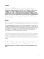
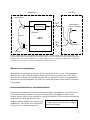
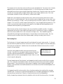
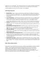
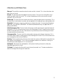
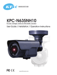
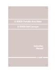
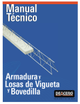
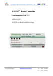
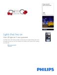
How to Choose an Acoustic Echo
Canceller
Application Note
Polycom Installed Voice
Business Group
September 2004
Introduction
Acoustic echo cancellers (AEC) greatly enhance the audio quality of a multipoint hands-free
communications system. They allow conferences to progress more smoothly and naturally, keep the
participants more comfortable, and prevent listener fatigue. An AEC solution that is poorly designed or
inappropriate for the location will not provide these benefits and can even degrade audio quality
significantly. There are many AEC solutions available, ranging in price from several dollars to several
thousands of dollars. There is also a broad range in quality and performance. This paper outlines some
guidelines for determining the performance needed in a given location, judging the performance of an AEC
solution based on specifications and listening tests, and ultimately finding the best AEC solution for any
application. Presented first, however, are guidelines for verifying that an acoustic echo canceller is
necessary in an application.
Why AEC?
Acoustic echo cancellation is useful in any hands-free telecommunications situation involving two or more
locations. Acoustic echo is most noticeable (and annoying) when delay is present in the transmission path.
This would happen primarily in long distance circuits, or systems utilizing speech compression (such as in
videoconferencing or digital cellular phones). Even though this echo might not be as annoying when there
is no delay (such as with short links between conference rooms in the same building or distance learning
over fiber-optic cable), room acoustics will still affect the sound and may hamper communication. Also,
howling can occur if the microphone is positioned too close to the speaker whether or not there is
transmission delay, and is eliminated by most acoustic echo cancellers.
Acoustic echo cancellers can be used in both narrow band (3.5 kHz) and wide-band (7 kHz) conferencing
systems. Narrow band applications include teleconferencing and low bit-rate video conferencing. Wideband applications include high quality teleconferencing and videoconferencing, as well as distance
learning. Users of wide-band conferencing systems should be particularly interested in using acoustic echo
cancellation, as it would allow them to make the most out of the additional audio capabilities of their
systems.
The primary beneficiaries of an echo canceller are the people at the far (or remote) end of the transmission
path. The near (or local) echo canceller prevents the echo of the remote peoples’ voices from being
returned (i.e. echoed) to them through the audio system. People speaking on the same (local) end as the
AEC should not notice the AEC if it is doing its job properly. While the people on the far end receive the
benefit of better audio quality, it also enables the conversation to flow more smoothly, benefiting both
parties.
2
Near End
Far End
Near speech
XMT
Nonlinear
Processing
Near speech +
echoes + distortion
Mic
Distortion
Echoes
AEC
RCV
Far speech
Speaker
Far speech
Figure 1: Illustration of the effects of AEC operation and room acoustics on the transmitted speech. The far speech that travels
through the receive path is not modified as it passes through the AEC. In an echo canceller that is poorly designed, there may be
residual echoes as well as distortion added to the near speech signal (these effects are described in detail later). This degrades
the speech that is transmitted, so that the poor audio quality is noticed on the far end.
Why not just use a speakerphone?
Speakerphones are half-duplex, which means that only one person can talk at a time. The speakerphone
determines which side is active (or louder) by comparing the signal levels on both sides. It turns off the
other side until the louder side is finished. Once one side has “captured” the circuit, most speakerphones
do not permit any sort of interruption. This inhibits the natural flow of conversation, especially if one party
is long-winded.
Acoustic Echo Cancellation vs. Line Echo Cancellation
Acoustic echo cancellation and line echo cancellation both address similar problems, and are often based
on the same technology. However, a line echo canceller generally cannot replace an acoustic echo
canceller, because acoustic echo cancellation is a more difficult problem. With line echo cancellation there
are generally only one or two reflections from
telephone hybrids or impedance mismatches in the With acoustic echo cancellation, the echo path
is complex and can vary continuously as people
telephone line. These echoes are usually delayed
move around the room.
by less than 32 ms, and do not change very
3
frequently, if at all. With acoustic echo cancellation, the echo path is very complex (dozens or hundreds of
reflections), lasts 100-200 ms, and can vary continuously during a conversation as people move around the
room. Acoustic echo cancellers are therefore much more complicated devices. While line echo cancellers
may have smaller price tags, they can’t perform under the conditions that acoustic echo cancellers can
handle.
Steps to Choosing An AEC
Now that the need for an acoustic echo canceller is recognized, the best AEC solution for the application
isdetermined based on the following four step selection process.
•
•
•
•
Find AEC products with the features and form factor needed for the application. There may
be several acceptable form factors. Even if one seems particularly suited to the application, consider
all of them for a broad selection of price and performance.
Eliminate products that don’t meet G.167 or the tail length requirements of the application.
Although these two factors are necessary, they are not sufficient. However, if an AEC solution does
not meet these requirements, it will most likely not sound very good at all, so don’t waste time
arranging listening tests. If it does meet these requirements, further testing and evaluation should be
done to ensure that it is appropriate for the application. When possible, find out the testing
environment as well as the results of the G.167 testing.
Judge audio quality and state machine performance by comparative listening. A panel of
several people should listen to the different solutions (preferably the same people, under similar
conditions, during a short time span). They should listen for the common problems echo cancellers may
have, as well as overall quality.
Choose the best solution. Weigh the performance, price, and convenience of each solution, and
choose the one that will work best in the application.
Step 1: Find AEC solutions with the features and form factor needed for the application.
Features
Certain features may be desirable for certain applications. For example, wide-bandwidth may be a
necessity for videoconferencing or high quality audio conferencing systems. For integrated systems, the
number and quality of microphones and speakers will be an issue. Automatic control of microphone and
speaker levels may be desirable. A graphical user interface (perhaps through a connection to a Windows
machine) may be needed. These kinds of features are too varied to be discussed in detail in this paper, but
will certainly be a consideration in the selection of an echo cancellation solution.
4
Form Factor
The form factor of the solution is very important because it determines how useful it is in an application.
The performance of the product may not matter if its form factor makes it inconvenient or impossible to use
in the desired application. Of course, there can usually be some flexibility in choosing a form factor.
Licensing an algorithm or buying chipsets may both be acceptable to an OEM (although one may be more
convenient), but a complete AEC solution would be out of the question for the OEM. (Indeed, that may be
what the OEM is using the chipset to build!) A list of common form factors for echo cancellation follows.
AEC for OEM’s
Different form factors depend on the volume an OEM plans to produce. Although an off-the-shelf solution
may be priced higher, at small volumes a total solution decreases development costs while reducing timeto-market. These are trade-offs to be weighed when making this choice:
•
•
•
Modules are suitable for moderate to high volume products and can speed the process of moving a
product to market. They provide full functionality and quick integration into a design. They can save a
great deal of resources during the design process, and can provide a value-added feature to systems
that may be used in a variety of applications.
Chipsets are best for high to very high volume products. They allow tighter integration into a board,
but require more effort for the board design.
Algorithms are best for very high volume products, especially embedded applications that are
sensitive to size and power consumption. Algorithms provide the opportunity to use the processor for
multiple tasks. They also can be ported to other platforms. Although algorithms are the cheapest per
unit at very high volumes, they require the most system integration work. This includes the supporting
code, software interfacing issues, and integration with other resources.
AEC Solutions for Integrators and End Users
Typically, a conferencing application will require one AEC per location. Depending on the size of the room
and other factors (such as the number of participants in each room), an AEC solution (packaged product) is
presented in a number of forms. The typical forms are:
•
•
•
AEC only (standalone AEC) - this is the least expensive to implement in a system but requires the
integrator or customer to supply all external equipment (such as microphones, amplifiers, and speakers)
for moving audio in and out of the product.
AEC for medium to large rooms - these products may contain microphone inputs and record inputs /
outputs in addition to the standard audio inputs and outputs required for AEC operation.
AEC for videoconferencing - these products may contain multiple inputs and outputs, or incorporate
“phone add” modules to permit the addition of a 2-wire conference (telephone call into the
videoconference).
5
Step 2: Eliminate the products that don’t meet G.167 or the tail length needs of the application.
It is relatively easy to determine how well an AEC cancels echoes. Most AEC products are based on the
same algorithm: the adaptive LMS digital filter. This is a very well-defined algorithm that has been used
for years. Since this process is well established, it is fairly easy to determine whether a manufacturer has
done an adequate job of implementing it.
The performance of the AEC can basically be judged by two criteria.
• First, the product must be compatible with the ITU G.167 recommendation for AEC.
• Second, the AEC must have an adequate tail length for the environment it is to be used in.
Although these criteria are necessary, they are not sufficient to determine whether an AEC is good enough.
There will most likely be several AEC solutions that meet these specifications. These are the specifications
that can be compared on paper. What remains are the characteristics that can only be evaluated by
comparative listening, and will make the most difference in how an AEC sounds.
G.167 Compliance or Compatibility
The ITU G.167 Recommendation for Acoustic Echo Controllers gives criteria for a number of performance
characteristics typically listed on manufacturers’ data sheets. These include such specifications as initial
convergence time (or rate of convergence), amount of cancellation, and bandwidth. G.167 compliance is a
good indication that the LMS algorithm (the actual echo canceling filter) has been implemented reasonably
well. It also means that the manufacturer has subjected the product to a series of standard tests, and that
the specifications are most likely based on valid experimental data. This makes the selection process
easier, because it sums up many different characteristics. Products can be eliminated easily based on
G.167 compliance, rather than by evaluating each performance characteristic individually.
When an echo canceller is G.167 compliant, the following specifications commonly found on data sheets
have met the requirements of the standard in the room in which the echo canceller was tested:
• Bandwidth
• Weighted Terminal Coupling Loss (or total cancellation)
• Initial Convergence Time (or convergence rate)
• Recovery Time After Echo Path Variation
Since most of the specifications found on data sheets are covered by G.167, it is not important to consider
each of these specifications in detail. The manufacturer’s equipment should have already been verified to
meet the requirements of the standard. If the product exceeds any of the requirements, this may improve
the audio quality to some degree. This improvement, however, will not be as significant as the effects of
the tail length and state machine. Therefore, all G.167 compliant devices should be considered equally
until the other factors have been evaluated.
6
Room Acoustics
G.167 testing is performed in real rooms. If the product meets the
Because of differences in room
requirements in these rooms, it is compliant. A device that is
acoustics, a device may be G.167
G.167 compliant in one room, however, might not be compliant in
compliant in one room and not
another. This is because the acoustics of all rooms are different.
another!
This flexibility allows manufacturers to test their products in the
types of rooms they were designed for and claim compliance.
However, this also means that the customer has the responsibility of determining whether the AEC will
operate in his or her particular environment. An AEC solution that was designed to operate in an office may
not work properly in a conference room. If an echo canceller were compliant in one room and not another,
it would most likely be due to a tail length that was too short for the second room. Since tail length is not
specified by G.167, it must be evaluated separately.
Tail Length
The tail length of an AEC is the length of time over which it can cancel echoes. The tail length of the echo
canceller should meet the requirements of the room it is to be operated in. This is directly related to the
reverberation time of the room. As the room reverberation time increases, a longer tail length will be
needed in that room. If the reverberation time is much longer than the tail length, a significant amount of
the echo will remain audible. However, excess tail length will not improve or degrade the performance of
the canceller. Determine the minimum tail length requirements for an application based on the typical
acoustics of rooms the product will be used in. Any products that do not meet or exceed that tail length
should not be used in that application.
There are two main factors that affect the reverberation time of a room. They are room size, and the
materials used to construct the walls and objects in the room. Most sound is absorbed when it strikes walls
or other surfaces. If materials are used that absorb sound well (such as carpet, curtains, or acoustic tile),
the reverberation will die out more quickly than if the room contains mostly reflective materials (hard wood,
glass, or plaster). If a room is small, the sound waves will bounce off the walls more frequently, and will be
absorbed more quickly.
The following formula is useful in determining the necessary tail length for an environment. It relates the
tail length to the room size and the number of cancelled reflections.
T = (N + 1) * d / c
• T is the tail length of the echo canceller
• N is the number of reflections cancelled
• d is the longest distance between walls
• c is the speed of sound (343 meters per second or 1125 feet per second at room temperature).
7
The equation assumes that both the microphone and the speaker are mounted on the same wall (which is
the worst case in terms of the number of reflections that will be cancelled). In that case, N must be an odd
integer because the even reflections travel away from the microphone.
For example, consider a 10x20x30 foot conference room with very reflective surfaces that requires 5 echoes
to be cancelled. In such a room, a tail length of 6 * 30 / 1125 = 160 ms would be needed. Figure 2 shows
how these reflections would travel back and forth across the room.
5th reflection
Mic
20'
n
4th Reflectio
3rd Reflectio
n
n
2nd Reflectio
1st Reflectio
n
Speaker
Direct
30 '
Figure 2: Longest Reflection Path from Speaker to Microphone for 5 Reflections
Howling Rejection
Howling rejection is important in cases where both parties are using hands-free communications systems.
In these types of systems, it is very easy for the open microphones and loudspeakers to produce acoustic
feedback, resulting in squealing tones (much like the feedback from a microphone in an auditorium). This
obviously prevents any useful conversation from taking place. The most common way to avoid this problem
is to implement howling rejection, typically done by shifting the frequency of the signal as it goes through
the canceller. G.167 specifies a maximum frequency shift for howling rejection, but does not actually
require that howling rejection be a part of an echo canceller. Generally, any AEC solution that does not
have howling rejection should be avoided.
8
Step 3: Judge audio quality and state machine performance by comparative listening.
Ideally, the AEC will let speech signals pass through it unharmed. This is actually the most difficult task in
both designing and measuring the performance of an acoustic echo canceller. The real difficulty is in
determining how the AEC sounds during double-talk, and whether it actually harms the sound quality by
inaccurately determining whether it is in a double-talk state. The state machine determines the mode of
the AEC and decides if it should be in double-talk, transmit, receive, or idle mode. The quality of the state
machine has the most drastic effect on the audio quality of the system, and is what will make the most
difference in the perceived quality between one echo canceller and another. Because the effects of the
state machine are most noticeable with dynamic signals (such as those present during a real conversation),
it is very difficult to quantitatively measure its performance. Consequently, the best way to evaluate the
audio quality of an AEC is by listening to it during a real conversation.
State machine
State machines make the difference between a good echo canceller and a bad echo canceller.
Unfortunately, most tests on echo cancellers are static: that is, the echo canceller remains in one state
while the test is done. For instance, the tests for initial convergence time and total echo cancellation are
done while the echo canceller is in receive mode. A great convergence rate does not guarantee that the
system will be able to determine when to converge during a dynamic conversation. If the state machine is
not robust, the other characteristics of the system will not mean much.
The state machine in an acoustic echo canceller chooses between one of the following four states:
• receive (where only “far in” speech is present)
• transmit (where only “near in” speech is present)
• double-talk (where both far-in and near-in speech are present)
• idle (where no speech is present)
The state machine must accurately choose between these modes for the AEC to operate properly. If it does
not choose properly, speech may be distorted by the AEC or the canceller may go out of convergence. Since
modes change frequently during conversations (especially when there are more than two people
participating), state machine performance is extremely important.
The basic factors of the state machine’s performance are
1. The accuracy of determining the correct state
2. Impact on the signal if the wrong state is selected
3. How gracefully it switches between states.
9
The two most critical states of the echo canceller are receive and double-talk. The receive state is the only
opportunity for the echo canceller to converge correctly. It is also the time when the echoes are most
noticeable because they are not masked by speech from the other side. During the receive state, the echo
canceller must converge rapidly and apply nonlinear processing to further reduce the echo. If the state
machine does not detect a receive state correctly, echoes remain audible.
Double-talk is most frequently mistaken for other states and has the most drastic effects on the sound
quality when it is incorrectly detected. If the state machine confuses double-talk for a receive state, it may
decide to start converging. If it does, it will try to converge to the near talker’s speech as well as the room
response. This causes the canceller to go out of convergence. It may also apply nonlinear processing. This
results in excessive attenuation, noisy or scratchy speech, or half-duplex behavior, depending on what
methods of nonlinear processing are implemented.
When the state machine switches between states, there should be no audible transition. On a poorly
implemented state machine, there could be noticeable changes in volume level, changes in background
noise level, or even audible clicks as the state machine changes states. These would be especially
noticeable during the beginning and end of pauses in conversation, or even between words. The state
machine may even transition several times between modes, making an annoying series of clicks.
The Listening Test
The listening test is the most important part of the evaluation of the acoustic echo canceller. It is the only
time to evaluate the performance of the state machine, which is the most important factor for audio quality.
The listening test environment should be taken into consideration if different echo cancellers are not all
tested in the same location.
A panel of several people should be chosen to evaluate the echo
canceller. If possible, the same people should evaluate all of the echo
cancellers under consideration during a short period of time. These
people should listen for the common problems listed in Table 3, as well
as for the overall audio quality.
The listening test is the only
way to evaluate state
machine performance.
The most important part of the evaluation is on the opposite end of the echo canceller (the far or remote
end). This is where the echo would be heard in the first place and most of the echo canceller’s problems
become evident. If the echo canceller is sold as part of a complete system (including microphones and
speakers), some evaluation also should be done on the near end to ensure all of the audio components are
of good quality.
On the opposite end of the echo canceller, either a handset or another echo canceller of the same type
should be used. A listening test should not be performed with a half-duplex speakerphone or a different
echo canceller on the other end. Otherwise, it would not be clear which end had problems.
Ideally, the operating environment for testing should be similar for all of the echo cancellers, since room
10
acoustics have such a large impact. If this cannot be arranged, at least consider the operating environment
differences in each case in the final decision. If possible, listen to the room acoustics with the echo
canceller disabled so the effects of the different rooms can be compared.
Seven Things to Listen For
•
•
•
•
•
•
•
Residual Echo. If there is excessive residual echo, the sound may have a hollow, distant quality or
there may even be distinct audible echoes. This is especially noticeable during the receive mode, when
there is no near speech to mask the echo. If this is due to a short tail length, the residual echo may
sound delayed.
Loss of Convergence. When the echo canceller loses convergence, the result is an audible residual
echo that could be louder than an echo with no echo canceller at all. This is generally caused when
the state machine mistakes a double-talk situation for a receive state. If this happens, the echo
canceller begins to adapt to the near talker’s speech as well as the echo, and goes out of convergence.
Howling. Pitched squealing noises may occur when both parties have hands-free systems with open
speakers and mics. This is caused by either a lack of howling rejection, or howling rejection that is not
working properly.
Attenuated Speech During Double-talk. Noticeable changes in volume levels may occur during
double-talk. This is caused when the state machine mistakes double-talk for a receive state, and
applies switch loss (attenuates the near signal to reduce the residual echo level).
Half-duplex Behavior. This is basically an extreme case of attenuated speech during double-talk. If
one of the sides is attenuated so much as to become inaudible, then it would be impossible for them to
interrupt the other party.
Clipped or Noisy Speech During Double-talk. Very harsh and annoying distortion can be added to
the speech signal when nonlinear processing (usually center clipping) is applied during double-talk.
The speech may be distorted beyond recognition. This occurs when the state machine reports a receive
state during double-talk.
Audible State Transitions. Audible changes in background noise level, clicks, or changes in overall
volume levels may be noticeable during state transitions. This may even occur between words or short
pauses in speech. This is caused by a state machine that switches between states too abruptly, or too
often.
Step 4: Choose the best solution.
At the end of the day, the initial list of echo cancellers should be narrowed down to a handful of acceptable
solutions. Those that would have been inconvenient to use, did not meet the G.167 or tail length
requirements of the application, or just did not sound good have been eliminated. Since all of the
remaining solutions are acceptable, the final task is to weigh the differences in price against the
differences in quality, convenience, level of support required, or time to market considerations. Any of
these remaining solutions, however, should not have performance problems.
11
A Short Glossary of AEC Related Terms
Near end The end of the connection where the echo canceller is located. This is where the echoes take
place. Also, see far end.
Far end The end of the connection opposite the echo canceller. The user on this end could be using a
handset or another hands-free system. This is where the performance of the echo canceller are most
noticeable. Also, see near end.
Double-talk The state of the echo canceller when there is speech on both ends of the connection. This is
the most difficult state to detect accurately, and most problems with audio quality occur during double-talk.
Bandwidth The frequency range the canceller passes without attenuation. For narrow-band (telephone)
applications, this is defined as 300-3000 Hz. For wide-band (videoconferencing, etc) applications this is
defined as 50-7000 Hz.
Initial Convergence Time The time it takes for the echo canceller to converge to a specified amount of
cancellation. In G.167, the canceller must have an Initial Convergence Time of 1 second, and must achieve
20 dB of cancellation within this time. Manufacturers may alternatively refer to the Convergence Rate of
the echo canceller on their data sheet.
Convergence Rate The rate at which the echo canceller converges when it begins to converge. This is
measured in dB per second. In order to meet the Initial Convergence Time of G.167, an echo canceller must
have a convergence rate of at least 20 dB/sec.
Howling Pitched, squealing tones that occur when hands-free systems at both ends of a connection have
open speakers and microphones. This is similar to microphone feedback in an auditorium. Howling can
cause damage to audio components if it is not attenuated.
Half-duplex Behavior of most speakerphones, which prevents howling and acoustic echo by only
allowing one party to talk at a time.
Tail length The length of the filter which cancels echoes (measured in ms). The more reverberation a
room has, the longer the tail length will need to be.
12
Technical Support
For support on the Vortex product line, call toll-free (USA/Canada) 888-248-4143, then select option 1, then
option 3.
For exclusive Integrator and Consultant focused support (through our PASS program), dial 1.408.474.2048;
this number will get you help on video and Vortex products.
For general technical support, dial 1.800.POLYCOM
Polycom Installed Voice Business group Contact
Information
Our address is:
9040 Roswell Road
Suite 450
Atlanta, GA 30350
770-350-4140 Phone
770-350-4142 Fax
Copyright © 2004 Polycom, Inc.
Polycom, the Polycom logo, and Vortex, are registered trademarks of Polycom, Inc. in the USA and various countries. All other brand names,
product names, and trademarks are the sole property of their respective owners. Rev. 09/04.
13