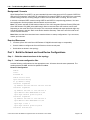
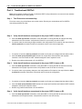
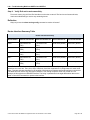
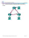
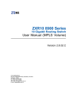
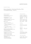
1
Lab – Troubleshooting Multiarea OSPFv2 and OSPFv3 Topology © 2013 Cisco and/or its affiliates. All rights reserved. This document is Cisco Public. Page 1 of 11 Lab – Troubleshooting Multiarea OSPFv2 and OSPFv3 Addressing Table Device R1 R2 R3 Interface IP Address Lo0 209.165.200.225/30 Lo1 192.168.1.1/24 2001:DB8:ACAD:1::1/64 FE80::1 link-local Lo2 192.168.2.1/24 2001:DB8:ACAD:2::1/64 FE80::1 link-local S0/0/0 (DCE) 192.168.12.1/30 2001:DB8:ACAD:12::1/64 FE80::1 link-local S0/0/0 192.168.12.2/30 2001:DB8:ACAD:12::2/64 FE80::2 link-local S0/0/1 (DCE) 192.168.23.2/30 2001:DB8:ACAD:23::2/64 FE80::2 link-local Lo6 192.168.6.1/24 2001:DB8:ACAD:6::1/64 FE80::2 link-local Lo4 192.168.4.1/24 2001:DB8:ACAD:4::1/64 FE80::3 link-local Lo5 192.168.5.1/24 2001:DB8:ACAD:5::1/64 FE80::3 link-local S0/0/1 192.168.23.1/30 2001:DB8:ACAD:23::1/64 FE80::3 link-local Objectives Part 1: Build the Network and Load Device Configurations Part 2: Troubleshoot Layer 3 Connectivity Part 3: Troubleshoot OSPFv2 Part 4: Troubleshoot OSPFv3 © 2013 Cisco and/or its affiliates. All rights reserved. This document is Cisco Public. Page 2 of 11 Lab – Troubleshooting Multiarea OSPFv2 and OSPFv3 Background / Scenario Open Shortest Path First (OSPF) is an open-standard link-state routing protocol for IP networks. OSPFv2 is defined for IPv4 networks, while OSPFv3 is defined for IPv6 networks. OSPFv2 and OSPFv3 are completely isolated routing protocols, meaning changes in OSPFv2 do not affect OSPFv3 routing, and vice versa. In this lab, a multiarea OSPF network running OSPFv2 and OSPFv3 is experiencing problems. You have been assigned to find the problems with the network and correct them. Note: The routers used with CCNA hands-on labs are Cisco 1941 Integrated Services Routers (ISRs) with Cisco IOS Release 15.2(4)M3 (universalk9 image). Other routers and Cisco IOS versions can be used. Depending on the model and Cisco IOS version, the commands available and output produced might vary from what is shown in the labs. Refer to the Router Interface Summary Table at the end of this lab for the correct interface identifiers. Note: Make sure that the routers have been erased and have no startup configurations. If you are unsure, contact your instructor. Required Resources 3 Routers (Cisco 1941 with Cisco IOS Release 15.2(4)M3 universal image or comparable) Console cables to configure the Cisco IOS devices via the console ports Serial cables as shown in the topology Part 1: Build the Network and Load Device Configurations Step 1: Cable the network as shown in the topology. Step 2: Load router configuration files. Load the following configurations into the appropriate router. All routers have the same passwords. The enable password is class, and the line password is cisco. Router R1 Configuration: enable conf t hostname R1 enable secret class ipv6 unicast-routing no ip domain lookup interface Loopback0 ip address 209.165.200.225 255.255.255.252 interface Loopback1 ip address 192.168.1.1 255.255.255.0 ipv6 address 2001:DB80:ACAD:1::1/64 ipv6 ospf network point-to-point interface Loopback2 ip address 192.168.2.1 255.255.255.0 ipv6 address 2001:DB8:ACAD:2::1/64 ipv6 ospf 1 area 1 ipv6 ospf network point-to-point interface Serial0/0/0 © 2013 Cisco and/or its affiliates. All rights reserved. This document is Cisco Public. Page 3 of 11 Lab – Troubleshooting Multiarea OSPFv2 and OSPFv3 ip address 192.168.21.1 255.255.255.252 ipv6 address FE80::1 link-local ipv6 address 2001:DB8:ACAD:12::1/64 ipv6 ospf 1 area 0 clock rate 128000 shutdown router ospf 1 router-id 1.1.1.1 passive-interface Loopback1 passive-interface Loopback2 network 192.168.2.0 0.0.0.255 area 1 network 192.168.12.0 0.0.0.3 area 0 default-information originate ipv6 router ospf 1 area 1 range 2001:DB8:ACAD::/61 ip route 0.0.0.0 0.0.0.0 Loopback0 banner motd @ Unauthorized Access is Prohibited! @ line con 0 password cisco logging synchronous login line vty 0 4 password cisco logging synchronous login transport input all end Router R2 Configuration: enable conf t hostname R2 ipv6 unicast-routing no ip domain lookup enable secret class interface Loopback6 ip address 192.168.6.1 255.255.255.0 ipv6 address 2001:DB8:CAD:6::1/64 interface Serial0/0/0 ip address 192.168.12.2 255.255.255.252 ipv6 address FE80::2 link-local ipv6 address 2001:DB8:ACAD:12::2/64 ipv6 ospf 1 area 0 no shutdown interface Serial0/0/1 © 2013 Cisco and/or its affiliates. All rights reserved. This document is Cisco Public. Page 4 of 11 Lab – Troubleshooting Multiarea OSPFv2 and OSPFv3 ip address 192.168.23.2 255.255.255.252 ipv6 address FE80::2 link-local ipv6 address 2001:DB8:ACAD:23::2/64 ipv6 ospf 1 area 3 clock rate 128000 no shutdown router ospf 1 router-id 2.2.2.2 passive-interface Loopback6 network 192.168.6.0 0.0.0.255 area 3 network 192.168.12.0 0.0.0.3 area 0 network 192.168.23.0 0.0.0.3 area 3 ipv6 router ospf 1 router-id 2.2.2.2 banner motd @ Unauthorized Access is Prohibited! @ line con 0 password cisco logging synchronous login line vty 0 4 password cisco logging synchronous login transport input all end Router R3 Configuration: enable conf t hostname R3 no ip domain lookup ipv6 unicast-routing enable secret class interface Loopback4 ip address 192.168.4.1 255.255.255.0 ipv6 address 2001:DB8:ACAD:4::1/64 ipv6 ospf 1 area 3 interface Loopback5 ip address 192.168.5.1 255.255.255.0 ipv6 address 2001:DB8:ACAD:5::1/64 ipv6 ospf 1 area 3 interface Serial0/0/1 ip address 192.168.23.1 255.255.255.252 ipv6 address FE80::3 link-local ipv6 address 2001:DB8:ACAD:23::1/64 © 2013 Cisco and/or its affiliates. All rights reserved. This document is Cisco Public. Page 5 of 11 Lab – Troubleshooting Multiarea OSPFv2 and OSPFv3 ipv6 ospf 1 area 3 no shutdown router ospf 1 router-id 3.3.3.3 passive-interface Loopback4 passive-interface Loopback5 network 192.168.4.0 0.0.0.255 area 3 network 192.168.5.0 0.0.0.255 area 3 ipv6 router ospf 1 router-id 3.3.3.3 banner motd @ Unauthorized Access is Prohibited! @ line con 0 password cisco logging synchronous login line vty 0 4 password cisco logging synchronous login transport input all end Step 3: Save your configuration. Part 2: Troubleshoot Layer 3 Connectivity In Part 2, you will verify that Layer 3 connectivity is established on all interfaces. You will need to test both IPv4 and IPv6 connectivity for all device interfaces. Step 1: Verify the interfaces listed in the Addressing Table are active and configured with correct IP address information. a. Issue the show ip interface brief command on all three routers to verify that the interfaces are in an up/up state. b. Issue the show run | section interface command to view all the commands related to interfaces. c. Resolve all problems found. Record the commands used to correct the configuration. d. Using the ping command, verify that IPv4 and IPv6 connectivity has been established on all directly connected router interfaces. If problems still exist, continue troubleshooting Layer 3 issues. © 2013 Cisco and/or its affiliates. All rights reserved. This document is Cisco Public. Page 6 of 11 Lab – Troubleshooting Multiarea OSPFv2 and OSPFv3 Part 3: Troubleshoot OSPFv2 Note: LAN (loopback) interfaces should not advertise OSPF routing information, but routes to these networks should be contained in the routing tables. Step 1: Test IPv4 end-to-end connectivity. From each router, ping all interfaces on the other routers. Record your results below as IPv4 OSPFv2 connectivity problems do exist. Step 2: Verify that all interfaces are assigned to the proper OSPFv2 areas on R1. a. Issue the show ip protocols command to verify that OSPF is running and that all networks are being advertised in the correct areas. Verify that the router ID is set correctly, as well for OSPF. b. If required, make the necessary changes needed to the configuration on R1 based on the output from the show ip protocols command. Record the commands used to correct the configuration. c. If required, re-issue the show ip protocols command to verify that your changes had the desired effect. d. Issue the show ip ospf interface brief command to verify that the serial interface and loopback interfaces 1 and 2 are listed as OSPF networks assigned to their respective areas. e. Resolve any problems discovered on R1 for OSPFv2. Step 3: Verify that all interfaces are assigned to the proper OSPFv2 areas on R2. a. Issue the show ip protocols command to verify that OSPF is running and that all networks are being advertised in their proper respective areas. Verify that the router ID is also set correctly. b. If required, make any necessary changes to the configuration on R2 based on the output from the show ip protocols command. Record the commands used to correct the configuration. c. If required, re-issue the show ip protocols command to verify that your changes had the desired effect. d. Issue the show ip ospf interface brief command to verify that all interfaces are listed as OSPF networks assigned to their proper respective areas. e. Resolve any problems discovered on R2 for OSPFv2. Step 4: Verify that all interfaces are assigned to the proper OSPFv2 areas on R3. a. Issue the show ip protocols command to verify that OSPF is running and that all networks are being advertised in their respective areas. Verify that the router ID is also set correctly. © 2013 Cisco and/or its affiliates. All rights reserved. This document is Cisco Public. Page 7 of 11 Lab – Troubleshooting Multiarea OSPFv2 and OSPFv3 b. If required, make the necessary changes to the configuration on R3 based on the output from the show ip protocols command. Record the commands used to correct the configuration. c. If required, re-issue the show ip protocols command to verify that your changes had the desired effect. d. Issue the show ip ospf interface brief command to verify that all interfaces are listed as OSPF networks assigned to their proper areas. e. Resolve any problems discovered on R3 for OSPFv2. Step 5: Verify OSPFv2 neighbor information. Issue the show ip ospf neighbor command to verify that each router has all OSPFv2 neighbors listed. Step 6: Verify OSPFv2 routing information. a. Issue the show ip route ospf command to verify that each router has all OSPFv2 routes in their respective routing tables. b. If any OSPFv2 routes are missing, troubleshoot and resolve the problems. Step 7: Verify IPv4 end-to-end connectivity. From each router, ping all interfaces on other routers. If IPv4 end-to-end connectivity does not exist, then continue troubleshooting to resolve any remaining issues. Part 4: Troubleshoot OSPFv3 Note: LAN (loopback) interfaces should not advertise OSPFv3 routing information, but routes to these networks should be contained in the routing tables. Step 1: Test IPv6 end-to-end connectivity. From each router, ping all interfaces on the other routers. Record your results as IPv6 connectivity problems do exist. Step 2: Verify that IPv6 unicast routing has been enabled on all routers. a. An easy way to verify that IPv6 routing has been enabled on a router is to use the show run | section ipv6 unicast command. By adding the pipe section to the show run command, the ipv6 unicast-routing command is displayed if IPv6 routing has been enabled. b. If IPv6 unicast routing is not enabled on one or more routers, enable it now. If required, record the commands used to correct the configuration. © 2013 Cisco and/or its affiliates. All rights reserved. This document is Cisco Public. Page 8 of 11 Lab – Troubleshooting Multiarea OSPFv2 and OSPFv3 Step 3: Verify that all interfaces are assigned to the proper OSPFv3 areas on R1. a. Issue the show ipv6 protocols command to verify that the router ID is correct and the expected interfaces display in their proper areas. b. If required, make any necessary changes to the configuration on R1 based on the output from the show ipv6 protocols command. Record the commands used to correct the configuration. It may be necessary to reset OSPF process by issuing the clear ipv6 ospf process command. c. Re-issue the show ipv6 protocols command on R1 to make sure changes took effect. d. Enter the show ipv6 route ospf command on R1 to verify that the interarea route summarization is configured correctly. R1# show ipv6 route ospf IPv6 Routing Table - default - 12 entries Codes: C - Connected, L - Local, S - Static, U - Per-user Static route B - BGP, R - RIP, I1 - ISIS L1, I2 - ISIS L2 IA - ISIS interarea, IS - ISIS summary, D - EIGRP, EX - EIGRP external ND - ND Default, NDp - ND Prefix, DCE - Destination, NDr - Redirect O - OSPF Intra, OI - OSPF Inter, OE1 - OSPF ext 1, OE2 - OSPF ext 2 ON1 - OSPF NSSA ext 1, ON2 - OSPF NSSA ext 2 O 2001:DB8:ACAD::/61 [110/1] via Null0, directly connected OI 2001:DB8:ACAD:4::/64 [110/129] via FE80::2, Serial0/0/0 OI 2001:DB8:ACAD:5::/64 [110/129] via FE80::2, Serial0/0/0 OI 2001:DB8:ACAD:23::/64 [110/128] via FE80::2, Serial0/0/0 e. Which IPv6 networks are included in the interarea route summarization shown in the routing table? f. If required, make the necessary configuration changes on R1. Record the commands used to correct the configuration. g. If required, re-issue the show ipv6 route ospf command on R1 to verify the changes. R1# show ipv6 route ospf IPv6 Routing Table - default - 11 entries Codes: C - Connected, L - Local, S - Static, U - Per-user Static route B - BGP, R - RIP, I1 - ISIS L1, I2 - ISIS L2 © 2013 Cisco and/or its affiliates. All rights reserved. This document is Cisco Public. Page 9 of 11 Lab – Troubleshooting Multiarea OSPFv2 and OSPFv3 O OI OI OI IA - ISIS interarea, IS - ISIS summary, D - EIGRP, EX - EIGRP external ND - ND Default, NDp - ND Prefix, DCE - Destination, NDr - Redirect O - OSPF Intra, OI - OSPF Inter, OE1 - OSPF ext 1, OE2 - OSPF ext 2 ON1 - OSPF NSSA ext 1, ON2 - OSPF NSSA ext 2 2001:DB8:ACAD::/62 [110/1] via Null0, directly connected 2001:DB8:ACAD:4::1/128 [110/128] via FE80::2, Serial0/0/0 2001:DB8:ACAD:5::1/128 [110/128] via FE80::2, Serial0/0/0 2001:DB8:ACAD:23::/64 [110/128] via FE80::2, Serial0/0/0 Step 4: Verify that all interfaces are assigned to the proper OSPFv3 areas on R2. a. Issue the show ipv6 protocols command and verify that the router ID is correct and that the expected interfaces are showing up under their proper areas. b. If required, make any necessary changes to the configuration on R2 based on the output from the show ipv6 protocols command. Record the commands used to correct the configuration. It may be necessary to reset OSPF process by issuing the clear ipv6 ospf process command. c. Verify that the configuration change has the desired effect. Step 5: Verify that all interfaces are assigned to the proper OSPFv3 areas on R3. a. Issue the show ipv6 protocols command to verify that the router ID is correct and the expected interfaces display under their respective areas. b. If required, make any necessary changes to the configuration on R3 based on the output from the show ipv6 protocols command. Record the commands used to correct the configuration. It may be necessary to reset OSPF process by issuing the clear ipv6 ospf process command. c. Verify that the configuration changes have the desired effect. Step 6: Verify that all routers have correct neighbor adjacency information. a. Issue the show ipv6 ospf neighbor command to verify that adjacencies have formed between neighboring routers. Step 7: Verify OSPFv3 routing information. a. Issue the show ipv6 route ospf command, and verify that OSPFv3 routes exist to all networks. b. Resolve any routing issues that still exist. © 2013 Cisco and/or its affiliates. All rights reserved. This document is Cisco Public. Page 10 of 11 Lab – Troubleshooting Multiarea OSPFv2 and OSPFv3 Step 8: Verify IPv6 end-to-end connectivity. From each router, ping all of the IPv6 interfaces on the other routers. If IPv6 end-to-end issues still exist, continue troubleshooting to resolve any remaining issues. Reflection Why not just use the show running-config command to resolve all issues? Router Interface Summary Table Router Interface Summary Router Model Ethernet Interface #1 Ethernet Interface #2 Serial Interface #1 Serial Interface #2 1800 Fast Ethernet 0/0 (F0/0) Fast Ethernet 0/1 (F0/1) Serial 0/0/0 (S0/0/0) Serial 0/0/1 (S0/0/1) 1900 Gigabit Ethernet 0/0 (G0/0) Gigabit Ethernet 0/1 (G0/1) Serial 0/0/0 (S0/0/0) Serial 0/0/1 (S0/0/1) 2801 Fast Ethernet 0/0 (F0/0) Fast Ethernet 0/1 (F0/1) Serial 0/1/0 (S0/1/0) Serial 0/1/1 (S0/1/1) 2811 Fast Ethernet 0/0 (F0/0) Fast Ethernet 0/1 (F0/1) Serial 0/0/0 (S0/0/0) Serial 0/0/1 (S0/0/1) 2900 Gigabit Ethernet 0/0 (G0/0) Gigabit Ethernet 0/1 (G0/1) Serial 0/0/0 (S0/0/0) Serial 0/0/1 (S0/0/1) Note: To find out how the router is configured, look at the interfaces to identify the type of router and how many interfaces the router has. There is no way to effectively list all the combinations of configurations for each router class. This table includes identifiers for the possible combinations of Ethernet and Serial interfaces in the device. The table does not include any other type of interface, even though a specific router may contain one. An example of this might be an ISDN BRI interface. The string in parenthesis is the legal abbreviation that can be used in Cisco IOS commands to represent the interface. © 2013 Cisco and/or its affiliates. All rights reserved. This document is Cisco Public. Page 11 of 11