1
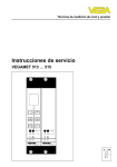
Level and Pressure
Operating Instructions
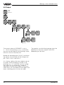
VEGAMET 514
%
100
-
+
ESC
OK
CONNECT
1
2
on
CONNECT
1
2
on
in
out
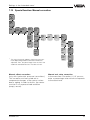
Contents
Contents
1
Product description
1.1
Function and configuration ................................................ 4
1.2
Approvals ........................................................................... 5
1.3
Features ............................................................................. 5
1.4
Technical data .................................................................... 6
1.5
Dimensions ......................................................................... 9
2
Mounting ................................................................................... 10
3
Electrical connection
4
3.1
Connection instructions ................................................... 11
3.2
Connection instructions for Ex approved
applications ....................................................................... 11
3.3
Wiring plan ........................................................................ 12
Adjustment
4.1
Indicating and adjustment elements ............................... 13
4.2
Adjustment system .......................................................... 14
4.3
Adjustment via PC ........................................................... 15
4.4
Configuration and parameter adjustment ....................... 16
4.5
Comparison: reduced menu – extended menu .............. 17
5
Setup .......................................................................................... 18
6
Settings in the "reduced menu"
2
6.1
Configuration of measurement loop ............................... 19
6.2
Adjustment with medium .................................................. 20
6.3
Adjustment without medium ............................................ 21
6.4
Scaling .............................................................................. 22
6.5
Integration time ................................................................ 23
6.6
Output ............................................................................... 24
6.7
Simulation ......................................................................... 25
6.8
Password, language, default, reset, menu mode .......... 26
VEGAMET 514
Contents
7
Settings in the "extended menu"
7.1
Configuration of measurement loop ............................... 27
7.2
Tare ................................................................................... 32
7.3
Monitoring ......................................................................... 33
7.4
Configuration of inputs ..................................................... 34
7.5
Configuration of outputs .................................................. 35
7.6
Adjustment........................................................................ 37
7.7
Conditioning ...................................................................... 38
7.8
Parameter adjustment of outputs ................................... 39
7.9
Simulation ......................................................................... 44
7.11 Password, language, menu mode .................................. 44
7.10 Special function: Reset .................................................... 44
7.12 Special function: Manual correction ................................ 45
7.13 Linearisation curves ........................................................ 46
7.14 Info .................................................................................... 49
7.15 Reset VEGAMET ............................................................. 50
8
Measured quantity and units ................................................ 51
9
Diagnostics
9.1
Maintenance ..................................................................... 52
9.2
Simulation ......................................................................... 52
9.3
Fault signal........................................................................ 52
9.4
Repair ............................................................................... 52
9.5
Error codes ...................................................................... 53
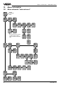
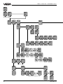
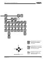
10 Menu schematics
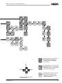
10.1 Menu schematic "reduced menu" .................................. 56
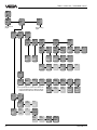
10.2 Menu schematic "extended menu" ................................. 58
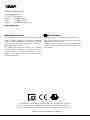
Safety information ...................................................................... 64
Note Ex area .............................................................................. 64
VEGAMET 514
3
Product description
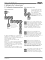
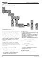
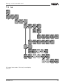
1 Product description
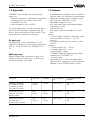
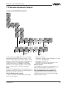
1.1 Function and configuration
VEGAMET 514 is a signal conditioning instrument for a number of applications, e.g.:
- level measurement
- gauge measurement
- process pressure measurement
- measurement with automatic correction
- etc.
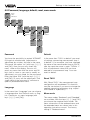
Function
The signal conditioning instruments power
the connected sensors and process their
analogue measuring data. The conditioning is
done via a special software consisting of
functional components (FB), input components (EB), output components (AB) as well
as DCS components (PB).
Configuration
The VEGAMET 514 signal conditioning instrument is constructed as module card in European size with 5 TE (= 25.4 mm) width. The
front plate contains an adjustment module
with LC display and keys. The front plate of
VEGAMET 514 N does not contain an adjustment module.
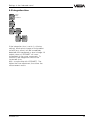
Software configuration
Output components
- current output
- voltage output
- DISBUS outputs
- failure output
- MET display
- relay outputs
Input component
- continuous current
input
- contact input
EB
AB
FB
PC/DCS components
- PC/DCS outputs
Functional component
- measurement loop
TAG 1
4
PB
VEGAMET 514
Product description
1.2 Approvals
1.3 Features
VEGAMET are available with the following
approvals:
- explosion protection: appropriate operating
instrument with intrinsically safe circuit
(VEGAMET 514 Ex)
- overfill protection acc. to WHG
- microcomputer-controlled signal conditioning instrument for continuous measurement
- adjustment module with LC display and 6
keys (not with VEGAMET 514 N)
- adjustable integration time
- two fixed and three user-programmable
linearisation curves
- fault monitoring
- fault signal and failure diagnosis via display
Inputs:
- 1 sensor input (capacitive electrode, pressure transmitter or other 4 … 20 mA
sensor)
- 1 correction input (for key, switch or level
switch)
Outputs:
- 1 current output 0/4 … 20 mA
- 1 voltage output 0/2 … 10 V
- 2 relay outputs (spdt)
- 1 DISBUS output for digital wiring and for
connection of VEGADIS 174
- 1 fail-safe relay
- adjustment also via PC with adjustment
software VVO; connection via the interface
adapter of the VEGACONNECT series
For such applications, please note the appropriate official documents (general type approval, test and conformity certificates). They
come with the respective instrument
Ex approval
For hazardous areas, certification acc. to
CENELEC defined in the conformity certificate
PTB no. Ex-95.D.2145 X for VEGAMET 514
Ex.
WHG approval
Signal conditioning instrument as part of an
overfill protection system acc. to WHG (test
certificate number see table).
Instrument
Oscillator
VEGAMET
Test certificate
no.
Auxiliary level switch
VEGASEL
Capacitive electrodes
EL 11 EX0, EL 21 EX0,
EL 24 EX0, EL 29 EX,
EL 31 EX0, EL 42 EX0
E17 EX
E18 EX
514 EX
Z-65.13-123
543 … 547
643
Pressure transmitters
D80, D81, D84, D86,
D84 EX, D86 EX
E23,
E23 Ex
514
514 EX
Z-65.11-130
543 … 547
643
Pressure transmitters
D77, D85, D87,
D77 EX, D85 EX, D87 EX
E22,
E22 Ex
514
514 Ex
Z-65.11-130
543 … 547
643
VEGAMET 514
5
Product description
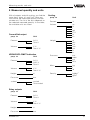
1.4 Technical data
Power supply
Operating voltage
Power consumption
Unom = 24 V AC (20 … 53 V), 50/60 Hz
= 24 V DC (20 … 72 V)
approx. 6 VA or approx. 4 W
Meas. data input
Number
Input type
Range
Sensor
Voltage
- at 4 mA
- at 20 mA
Current limitation
Detection line break
Detection short-circuit
Min. adjustment delta
Connection cable
max. resistance per wire
Resolution
Linearity error
Temperature error
1 input
active two-wire input, analogue (sensor is
powered by VEGAMET)
4 … 20 mA
capacitive electrodes, pressure transmitters,
process pressure transmitters, differential
pressure transmitters
approx. 18 V DC
approx. 15 V DC
at approx. 26 mA, short-circuit-proof
< 3.6 mA
> 21 mA
2 % of the entered sensor values
2-wire standard cable (screening
recommended)
35 Ω
1 µA
0.025 % at 4 … 20 mA
0.04 %/10 K at 4 … 20 mA
Correction signal input
Number
Function
Voltage
Current
External cable resistance
1 input
switching signal for triggering corrections
or special relay modes via
external switching contact
5 V (from instrument)
5 mA
€150 Ω
≤
Current output
Number
Function
Range
Load
Resolution
Linearity error
Temperature error
6
1 output
analogue output of the processing results
adjustable between 0 … 20 mA
max. 500 Ω
1 µA
0.05 % (relating to 20 mA)
0.05 %/10 K (relating to 20 mA)
VEGAMET 514
Product description
Voltage output
Number
Function
Range
Current
Resolution
Linearity error
Temperature error
1 output
analogue output of the processing results
adjustable between 0 … 10 V
max. 1 mA
0.5 mV
0.05 % (relating to 10 V)
0.06 %/10 K (relating to 10 V)
Relay output
Number
Contact
Contact material
Turn-on voltage
Switching current
Breaking capacitance
Min. switching hysteresis
(Low-/High delta)
2 switching relays
1 fail-safe relay
floating spdt
AgNi, hard gold plated
min. 10 mV DC
max. 250 V AC/DC
min. 10 µA
max. 3 A AC, 1 A DC
max. 500 VA, 54 W
0.5 %
DISBUS output
Function
Connection cable
max. cable length
for linking the signal conditioning instruments
and for connection of digital indicating
instruments
2-wire standard cable (screening is
recommended)
1000 m
Indicating elements
Clear text indication
(not available with VEGAMET 514N)
Analogue indication
(not available with VEGAMET 514N)
LEDs in front plate
LC display
- 4-line, 6 digits each
- background lighting
LED chain consisting of:
- 11 segments 0 % … 100 %
- shows the actual value of the measurement
loop
green: operating voltage on
red: fault signal (LED lights with deenergised
relay)
yellow: relay status (standard setting:
LED lights with energised relay)
Adjustment elements
Front plate
Circuit board
VEGAMET 514
6 keys for configuration and parameter
adjustment
(not available with VEGAMET 514N)
rotary switch for adjustment of the instrument
address on DISBUS
7
Product description
Ambient conditions
Permissible ambient temperature
Storage and transport temperature
-20°C … +60°C
-40°C … +80°C
Electrical connection
Multiple plug component
Carrier BGT 596 (Ex)
Housing type 505
acc. to DIN 41 612, series F, 33-pole, 3 lines
d, b, z (partly equipped)
connection to the appropriate module
connection to screw terminals (max. 2.5 mm2 )
Electrical protective measures
Protection
- unassembled
- mounted into
carrier BGT 596
- front side completely equipped
- upper and lower side
- wiring side
- mounted into
housing type 505 or type 506
- terminal side
- housing general
Protection class
Overvoltage category
IP 00
IP 40
IP 20
IP 00
IP 20
IP 30
II (in housing type 505)
II
Electrical separating measures
Reliable separation acc. to
VDE 0106, part 1 between
- reference voltage
- isolation resistance
Galvanic isolation
- reference voltage
- isolation resistance
Potential separation
- reference voltage
- isolation resistance
Common reference potential at
Mechanical data
Series
Dimensions
power supply, fail safe and level relay
and measuring data inputs
250 V
2.3 kV
between the relay outputs
250 V
1.4 kV
between DISBUS and outputs
50 V
0.5 kV
voltage and current output,
correction signal output
module unit for carrier BGT 596
or housing type 505
B = 25.4 mm (5 TE), H = 128.4 mm, T = 162 mm
CE conformity
VEGAMET 514 and VEGAMET 514 Ex signal conditioning instruments meet the protective
regulations of EMC (89/336/EWG) and NSR (73/23/EWG). Conformity has been judged
acc. to the following standards:
EMC
Susceptibility
EN 50 081 - 2: 1993
Immission
EN 50 082 - 2: 1995
NSR
EN 61 010 - 1: 1993
8
VEGAMET 514
Product description
Ex technical data
Power supply
Operating voltage
Reference voltage
Unom corresponds to non-Ex version
Um = 250 V AC or 125 V DC
Meas. data input (intrinsically safe circuit) on VEGAMET 513 Ex 2-times available
Flame proofing
[EEx ia] IIC, [EEx ia] IIB, [EEx ib] IIC or
[EEx ib] IIB
Max. values
- voltage
- current
- power
Characteristics
Effective inner inductance LI
Effective inner capacitance CI
UO = 20 V
I O = 128 mA
PO = 640 mW
linear
negligible
negligible
EEx ia IIC
EEx ia IIB
EEx ib IIC
EEx ib IIB
Max. permissible outer inductance LO (mH)
0.5
1
1.5
2
2
9
Max. permissible outer capacitance CO (nF)
97
78
68
486
200
1000
The intrinsically safe circuits are reliably separated from the non-intrinsically safe circuits up
to a peak value of the nominal voltage of 375 V. The max. voltage on the non-intrinsically
safe circuits should not exceed 250 Veff in case of failure.
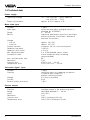
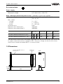
1.5 Dimensions
Multipoint
connector
128,4
5 TE
100
Circuit board 100 x 160 x 1.5
European size
15
5,5
VEGAMET 514
162
25,4
9
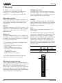
Mounting
2 Mounting
VEGAMET 514 signal conditioning
instruments can be either mounted with a
module in a carrier BGT 596 or BGT
596 Ex.M or in a single housing type 505.
Transparent cover
To protect the instrument against unauthorised adjustment, the front plate of VEGAMET
can be provided with a lockable transparent
cover (supplied with the instrment).
Mounting in carrier
Mount the respective module (standard or Ex
version) in your carrier. Wire the terminals of
the multipoint connector according to the
wiring plan.
Module
Multipoint connector DIN 41 612, series F, 33pole (d, b, z) with coded pins and mounting
material for mounting in carrier BGT 596 or
BGT 596 Ex.M.
Module Ex
Multipoint connector DIN 41 612, series F, 33pole (d, b, z) with coded pins, Ex separating
chamber and mounting material for mounting
in carrier BGT 596 Ex.M.
The multipoint connector is available in the
following versions:
- Wire-Wrap standard connection
1.0 x 1.0 mm
- Plug connection 2.8 x 0.8 mm
- Termi-Point standard connection
1.6 x 0.8 mm
- Soldering connection
- Screw terminals 2 x 0.5 mm 2
Coding
To prevent an interchanging of the different
signal conditioning instruments, the multipoint
connector of carrier or the housing can be
provided with coded pins.
Note:
The coding is absolutely necessary for Ex
instruments!
The multiple plug of the signal conditioning
instrument is equipped with respective holes
(mechanical coding). Instrument coding
ensures that the different signal conditioning
instruments cannot be interchanged. The
appropriate coded pins are supplied with
each module or housing. Equip the multipoint
connector with these coded pins acc. to the
following table.
Instrument
Ex
coding
coding
VEGAMET 514
a3 / c5
––
VEGAMET 514 Ex
a3 / c5
c23
z b d
For further mounting information, see the
operating instructions of the carrier.
a c
o1o
a3
o3o
o5o
c5
o7o
Mounting in single housing
Either screw the housing socket directly to
the mounting plate or plug it onto a carrier rail
(35 x 15 acc. to EN 50 022 or 32 acc. to
EN 50 035). Connect the terminals according
to the wiring plans on the following pages.
For further mounting information see the operating instructions of the housing.
o9o
o11o
o13o
o15o
o17o
o19o
o21o
o23o
c23
o25o
o27o
o29o
o31o
10
VEGAMET 514
Electrical connection
3 Electrical connection
3.1 Connection instructions
Note the following instructions for electrical
connection:
- The connection must be made acc. to the
local installation standards (e.g. in Germany acc. to the VDE-regulations).
- The wiring between VEGAMET and sensor
can be done with standard two-wire cable.
- If strong electromagnetic interferences are
expected, screened cable is recommended. The screening must be earthed
on both ends.
- The line resistances stated in the technical
data must not be exceeded.
- If overvoltages are expected, we recommend a sensor electronics with integrated
overvoltage protection or the installation of
VEGA overvoltage arresters.
- The voltage supply of VEGAMET must
provide with extra-low voltage to ensure
protection class II. When using VEGASTAB
593 a reliable separation from the mains
circuits acc. to DIN VDE 0106, part 101 is
ensured.
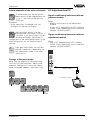
3.2 Connection instructions
for Ex approved applications
The signal conditioning instruments must be
generally mounted outside the hazardous
areas, or special Ex protective measures
must be taken.
Ex separating chamber
To ensure sufficient "air and creep distance",
an Ex separating chamber must be mounted
to the connections of VEGAMET. Lead the
cables through the Ex separating chamber
and connect them. Fasten the Ex separating
chamber with the lower screw. Note the
operating instructions of the carrier BGT 596
Ex.M.
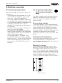
Protection in Ex applications
In Ex applications a protection class of IP 20
must be maintained. To accomplish this,
cover the gaps or free modules from the front
with suitable blind covers.
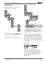
Mounting in carriers
If you mount your VEGAMET with Ex approval in a carrier, you have to use a VEGAEx module. Keep a distance of at least 10
mm (2 TE) to module cards of other manufacturers. If you want to mount VEGAMET at the
utmost left position in the carrier, you have to
mount a blind cover with at least 20 mm
(4 TE) in front of the module of the instrument.
%
100
+
-
ESC
OK
CONNECT
1
2
on
Blind cover (4 TE)
VEGAMET 514
11
Electrical connection
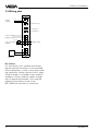
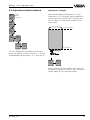
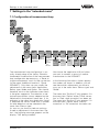
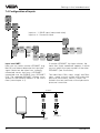
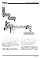
3.3 Wiring plan
Supply
voltage
L (+)
N (-)
d b
2 +
z
-
6
Fail safe relay
10
Level relay 1
12
Level relay 2
16 +
Current output
+
18 20 +
Voltage output
Correction signal
(input 4)
22 +
+
-
-
24
DISBUS output
28
+
+
30
-
32
-
Sensor
(input 1)
Ex version
For connection of Ex certified instruments,
please note the instructions in the attached
official documents as well as the valid mounting regulations. Make sure that the Ex separating chamber is mounted to the multipoint
connector. Always lead the cables through
the Ex separating chamber. Also note the
operating instructions of the carrier
BGT 596 Ex.M and the Ex instructions.
12
VEGAMET 514
Adjustment
4 Adjustment
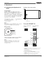
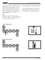
4.1 Indicating and adjustment elements
Position of the rotary switch
Circuit board
A rotary switch is located on the circuit
board. It is used for adjustment of the instrument address on DISBUS. This setting is
necessary if several VEGAMET signal conditioning instruments are linked via the DISBUS
or if you control a VEGADIS 174 indicating
instrument via the DISBUS.
The adjustment range 1 … F corresponds to
the DISBUS addresses 1 … 15.
Factory setting: 1
Rotary switch
Note:
With address 0 the VEGAMET does not participate in the DISBUS communication.
Front plate VEGAMET 514
Rotary switch
without adjustment
module
A
3 4 5 6
7 8 9
B C DE
2
with adjustment
module
10
11
12
1
13
14
15
2
%
F 0 1
100
The set instrument address on the DISBUS
can be indicated via the LC display.
Note
If several VEGAMET are linked via the
DISBUS, each address must only be
assigned once!
+
3
CONNECT
1
2
on
514
4
5
6
7
3
ESC
OK
CONNECT
1
2
on
514
1 LCD (4 lines with 6 figures each, illuminated) for clear text
indication
2 LED chain (yellow) for quasi-analogue indication of the
measured value
3 Keys for menu adjustment
4 Connection socket for VEGACONNECT
5 LED (yellow) lights if the relay is energised (standard
setting)
6 LED (red), lights if fail safe relay is deenergised
7 LED (green), lights if operating voltage is on
VEGAMET 514
13
Adjustment
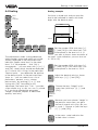
4.2 Adjustment system
Indicating and adjustment module
Indication of
- measured value
- menu item
- parameter
Branching point, i.e. jump to the
next lower menu with [OK]
Depending on the menu item, change value
or choose out of a list
%
100
+
-
Choose menu item
Depending on the menu item, interrupt
adjustment or change to the next higher
menu
Depending on the menu item, save the set
value or change to the underlying menu
ESC
Reduced menu - extended menu
Two menu modes are available: the mode
"reduced menu" and the mode "extended
menu".
Note:
VEGAMET 514 is preset to automatically
place in the menu mode "reduced menu"!
In the majority of all applications, you can
carry out the necessary settings in this menu
mode (see also chapter 4.5 Comparison of
the menu modes).
Adjustment structure
The adjustment is made via 6 keys in conjunction with the text display. The jump from
the measured value display to the underlying
menu is made with [OK]. Use [–>] or [<–] to
change within this menu level from one menu
item to the other. A branching point is
indicated by the symbol ▼ and enables with
[OK] a jump to the underlying menu item.
Parameters can be recognised by the
absence of the symbol ▼. The value of the
parameters can be modified with [+] or [–] or
chosen out of a list. The modified value can
be saved with [OK]. To interrupt a setting
(without saving the modification), you have to
push [ESC]. A jump back to the next higher
menu item is made with [ESC]. 15 minutes
14
OK
after pushing a key for the last time, an automatic reset to the measured value display is
triggered. A jump back to the next higher
menu level with [ESC] is possible from each
menu item , even if no connecting line is
shown in the menu schematics.
Add'l
functions
ESC
Password
off
ESC
Language
English
ESC
ESC
ESC
TAG 1
to de
fault
Reset
TAG 1
Menu
mode
Reduced
If you are in the utmost right menu item of a
menu row and push the [–>] key, you will
immediately reach the utmost left menu item
of this row. You also reach immediately the
right menu item from the left one, if you push
the [<–] key.
These shortcuts (shown with a broken line)
are not shown in the menu schematics in
order to give a better overview.
Volt
output 1
prop.
to
Percent
Unit
0,0%
Volt
output
0/10V
Failure
mode
0V
Volt
limitation
on
VEGAMET 514
Adjustment
Format examples of the menu schematic
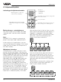
4.3 Adjustment via PC
In white letters you see the parameters which can be modified with the
[+] or [–] key and saved with the
[OK] key.
Examples:
- In the menu item "Language" you can
change from German to English.
Signal conditioning instrument with adjustment module
Language
English
Bold print/italic entries, e.g. the
measurement loop name "TAG-No. 1"
can differ if you have made a corresponding parameter adjustment or
configuration of the measurement loop. In the
menu schematics you will see the factory
settings.
Param.
TAGNo. 1
▼
Volt
at
0%
0,000
Light grey menu items are only displayed if necessary (depending on
the adjustments made in the other
menu items).
Change of the menu mode:
Setup
- directly via the keys of the adjustment
module
- or with a PC, equipped with VVO software
(VEGA Visual Operating) and an interface
adapter VEGACONNECT.
Signal conditioning instrument without
adjustment module
Setup
- with a PC, equipped with VVO software
(VEGA Visual Operating) and an interface
adapter VEGACONNECT.
%
100
+
-
Move from the display of measured value
(TAG-No.1) to the menu item "Menu mode
reduced". Now push [+] twice until "Menu
mode Extended" appears, then push [OK].
ESC
OK
CONNECT
1
2
VEGACONNECT
on
515
TAGNo. 1
%
xx,x
PC with VVO software
Param.
TAGNo. 1
Configuration
Add'l
functions
Password
off
Language
English
TAG 1
to default
Reset
TAG 1
Menu
mode
Reduced
Extended
VEGAMET 514
15
Adjustment
4.4 Configuration and parameter
adjustment
Independent of whether you set up your
VEGAMET via the keys of the adjustment
module or via a PC with the software VVO,
the procedure is always the same.
Proceed in the following sequence:
- configuration (if not already configured as
factory setting)
- parameter adjustment.
In this operating instruction manual, the adjustment steps are described which are
directly carried out on the keys of VEGAMET.
The adjustment via the software VVO is described in a separate manual.
Configuration
Configuring means assigning or setting
(once) function. VEGAMET requires a (mostly
once) basic co-ordination, determining the
applications and the assignments of the
inputs and outputs. Choices can be made
from existing functions and options. This
procedure is called configuration. The signal
conditioning instruments are delivered with a
configuration which only needs to be
changed in special cases.
The basic configuration includes the following
steps:
1 Configuration measurement loop
• Choose the kind of application (level,
gauge…)
• Choose sensor type (capacitive, hydrostatic…)
• Specify application (standard, level
difference…)
• Determine options (no option, corrections…)
16
Note:
The measurement loop configuration can only
be modified if a "Reset to single measurement" has been carried out previosly (under
"Additional functions" in the extended menu).
If you only want to modify the sensor type,
you first have to carry out "Reset TAG 1"
(under "Additional functions" in the reduced
menu).
2 Configuration, inputs
• Determine from where your VEGAMET
receives the input data (sensor, other
VEGAMET)
• Enter sensor characteristics values (meas.
range, current range)
3 Configuration, outputs
• All outputs (except fail-safe relay) can be
assigned to a sensor or can be switched
off.
After basic configuration, VEGAMET starts
operating and indicates the actual measured
value. The other configurations should be
carried out after the parameter adjustment.
Parameter adjustment
Parameter adjustment means changing the
values. Signal conditioning instruments have
many parameters, the values of which can be
modified, such as for example the integration
time of 0 … 600 s. The modification of these
values is called parameter adjustment. The
parameter adjustment does not influence the
configuration. Take notice that parameter
adjustment is only possible after a configuration has been done (e.g. set values of the
current input when the current output has
been assigned).
VEGAMET 514
Adjustment
4.5 Comparison: reduced menu – extended menu
In the table the most important functions of VEGAMET 514 are listed – each with a mark
indicating in which menu mode the functions are available.
Function
Reduc. Ext.
menu menu
Adjustment with medium
x
x
Adjustment without medium
x
x
Set integration time
x
x
Simulation
x
x
Switch over current output (4/20 mA, 0/20 mA, 20/4 mA, 20/0 mA)
x
x
Switch over voltage output (2/10 V, 0/10 V, 10/2 V, 10/0 V)
x
x
Changeover relay mode (overfill protection – dry run protection)
x
x
Scaling (display)
x
x
Change menu mode (reduced – extended)
x
x
Change menu language
x
x
Activate/deactivate password
x
x
Change sensor type
x
x
Change measurement loop name
x
x
Reset measurement loop (Reset TAG)
x
x
Reset measurement loop to default (TAG to default)
x
x
Use correction input
–
x
Edit linearisation curves
–
x
Change mode (e.g. level – gauge)
–
x
Select different reference values for outputs
–
x
Define output behaviour (current/voltage output) in case of failure
–
x
Adapt VEGAMET to sensor characteristics values
–
x
Offset correction during adjustment
–
x
Adjust relay switching delay
–
x
Reset level
–
x
Assign inputs (from another VEGAMET)
–
x
Switch on/off current/voltage limitation
–
x
Individual setting of current/voltage output values between 0 … 20 mA/0 … 10 V
–
x
Manual offset correction
–
x
Manual real value correction
–
x
Info indication
–
x
VEGAMET 514
17
Setup
5 Setup
• Adjust the VEGAMET instrument address
on the circuit board by means of the rotary
switch (only necessary, if several
VEGAMET are connected by means of
DISBUS).
• Install VEGAMET.
• Connect sensor and power supply.
• After switching on, the display indicates for
approx. 10 secs the instrument type and
the software version, e.g. "MET 514
V1.12".
• If a measurement loop has not yet been
configured, the display shows "Configuration", the red failure LED also lights. In this
case, proceed as described under "6.1
Configuration of measurement loop".
• If a measurement loop is already
configured, the display shows a value, e.g.
"TAG-No. 1 21.8 %".You can now carry out
the settings, as described in the chapter "6
Settings in the reduced menu".
18
VEGAMET 514
Settings in the "reduced menu"
6 Settings in the "reduced menu"
6.1 Configuration of measurement loop
TAGNo. 1
%
xx,x
Choose sensor type
TAG- Meas.
No. 1 value
%
indication
xx,x
Param.
TAGNo. 1
Configuration
Param.
TAGNo. 1
Add'l
functions
Password
off
Sensor
type
Hydrostatic
capacitive
VEGADIF
Name measurement loop
TAG
name
TAG No. 1
Language
English
TAG 1
to default
It is only possible to
modify the sensor type,
when a "Reset TAG 1" was
carried out before.
Reset
TAG 1
Delete
TAG
1?
Reset
OK ?
Reset
Now!
OK ?
By default, VEGAMET 514 is configured for
connection to a hydrostatic sensor. If, for
example, you use a capacitive electrode, you
have to proceed as follows:
Move to the menu item "Sensor type
Hydrostatic".
Push [+] or [–] once. The word "Hydrostatic"
flashes. You are now in the editing mode.
Continue pushing [+] or [–] until the display
shows "Sensor type capacitive". You are still
in the editing mode.
Now push the [OK] key. By doing this, you
save the settings and quit the editing mode.
Push [+] or [–] once. The first character of the measurement loop name,
in this example the letter T, flashes
(editing mode). Continue pushing the
[+] or [–] key, by doing this you scroll
through the alphabet, through the row of
numbers and through a list of characters.
TAG
name
TAG No. 1
When you have reached the requested character, push [–>]. The
next character is activated and begins flashing. Scroll again with [+]
and [–] to the requested character. With [–>]
you again move to the next character.
TAG
name
TAG No. 1
When you have finished the last
position of the name and you have
"written" the name of the measurement loop in this way, you have to
push [OK] to save the setting. If you quit the
menu item without saving, the name of the
measurement loop is again "TAG-No. 1".
TAG
name
Ves.4
Hall 3
Ves.4
Hall 3
%
27,8
VEGAMET 514
Configuration
You can modify the measurement loop name "TAGNo. 1", if you want a more
useful designation.
Two lines with six figures
each are available. To do
this, move to the menu item
"TAG name …".
In the display of measured value and
all other menu items in which the
measurement loop name is shown,
you will now see the new designation.
19
Settings in the "reduced menu"
6.2 Adjustment with medium
Adjustment example
You can either carry out the adjustment with
medium or without medium. Adjustment with
medium means that you carry out the adjustment taking the actual level into account. To
carry out an adjustment with medium, it is
necessary to know the percentage value of
the actual vessel filling.
You know that your vessel is actually
filled up to 80%. Move to the menu
item "Max. adjust at % 100.0". Push
the [–] key briefly, so that the figure
100.0 flashes (editing mode).
TAGNo. 1
%
xx,x
Param.
TAGNo. 1
Maxadjust
at %
100,0
Maxadjust
at %
80,0
Continue pushing [–] until the figure
80.0 appears on the display. Now
push [OK] to save the adjustment.
Minadjust
at %
0,0
Later, when your filling is, for example, 10 %, go to the menu item
"Min. adjust at % 0.0". Briefly push
[+], until the figure 0.0 flashes
(editing mode).
Minadjust
at %
10,0
Continue pushing [+] until "10" appears on the display. Now push [OK]
to save the adjustment.
Adjustment
with
medium
Minadjust
at %
0,0
Maxadjust
at %
100,0
In this procedure, the percentage values
which correspond to the actual min. and max
fillings are entered. The adjustment sequence
of the min. and max. value is unimportant.
When you know, for example, that your filling
is actually 80 %, you can enter in the menu
max. adjustment the value "80". Later when
your filling is, for example, 10 %, you enter in
the menu min. adjustment the value "10".
You can of course carry out the adjustment
with medium at 0 % and 100 % filling. Note:
The figures 0 % and 100 % must flash (editing mode), before they can be saved with the
[OK] key.
The bigger the difference between the two
adjustment points, the more precise the
measurement over the whole measuring
curve. An adjustment at 0 % and 100 %
would be ideal. For practical reasons, it is not
always possible to completely empty or fill a
vessel. The distance between the two adjustment points, however, should be at least
10 % of the sensor range.
20
VEGAMET 514
Settings in the "reduced menu"
6.3 Adjustment without medium
TAGNo. 1
%
xx,x
Adjustment example
You know the data of the sensor, i.e. you
know that at 0 % filling the sensor delivers a
current of 4.2 mA and at 100 % filling a current of 15.5 mA. Enter these values in the
menu items.
Meas.
value
indication
Param.
TAGNo. 1
15.5 mA at 100 %
Adjustment
with
medium
without
medium
0%
at
mA
4,000
100%
at
mA
20,000
4.2 mA at 0 %
For this adjustment procedure you have to
enter two sensor current values (4 … 20 mA)
corresponding to the levels 0 % and 100 %.
0%
at
mA
4,200
100%
at
mA
15,500
Enter in these two menu items the values of
the senor. Use the [+] and [–] keys to set the
values and [OK] to save the values.
VEGAMET 514
21
Settings in the "reduced menu"
Scaling example
6.4 Scaling
TAGNo. 1
%
xx,x
You have a raised tank and you want the
level to be indicated in meters with three
digits after the decimal point.
Meas.
value
indication
Param.
TAGNo. 1
Adjustment
100 %
Signal
conditioning
h=4.5 m
0%
Scaling
Integr
ation
time s
0
0%
corresponds
0
100%
corresponds
1000
2.341 m
Decimal
point
888,8
prop.
to
undefined
Unit
––
The adjustments under scaling determine
which number values and which unit will be
actually displayed in the measured value
indication (upper menu item). In the menu
items "0 % corresponds…" and "100 %
corresponds…" you can enter with [+] or [–]
and [OK] values which should be displayed
at 0 % and at 100 % filling. In the menu item
"Decimal point…" you determine the position
of the decimal point. In the next menu item
"prop. to…" you can select from a list of
parameters: percent, mass, volume,
pressure etc. by pushing [+] or [–] and
saving with [OK]. According to this
adjustment, the menu item "Unit…" provides
a new choice, e.g. m, dm, cm, mm, ft, yd and
in, if you have selected the parameter
"Height" (compare chapter "8 Measured
quantity and units").
Set the number 1500 (with keys [+],
[–] and [OK]) in this menu item. This
corresponds to the level at 0 % (if
you want to have a lower resolution of
the meas. value indication, you can also set
to 150 or 15).
0%
corresponds
1500
100%
corresponds
4500
Set the number 4500 (with keys [+],
[–] and [OK]) in this menu item. This
corresponds to the level at 100 %.
Decimal
point
8,888
Adjust the decimal point as shown
(with keys [+], [–] and [OK]).
prop.
to
Choose the term "Height" in this
menu item (with keys [+], [–] and
[OK]).
Height
Percent
Pressure
Mass
Unit
m
dm
cm
….
TAG No. 1
m
2,341
22
h=1.5 m
Because you have chosen "Height" in
the previous menu item, you get a
choice of several units (mm, dm, cm,
m, yard…). Choose m (with the keys
[+], [–] and [OK]).
In the meas. value indication the
scaled value is shown.
VEGAMET 514
Settings in the "reduced menu"
6.5 Integration time
TAGNo. 1
%
xx,x
Meas.
value
indication
Param.
TAGNo. 1
Adjustment
Signal
conditioning
Scaling
Integr
ation
time s
0
If the integration time is set to 0 s (factory
setting), each quick change of the product
surface (e.g. waves) will be immediately
detected and interpreted as level change. All
output values of VEGAMET will react
immediately to the wave movements. To
avoid this, the integration time can be
increased (max.
600 s are possible with VEGAMET). The
higher the time adjustment, the slower the
measurement reacts.
VEGAMET 514
23
Settings in the "reduced menu"
6.6 Output
TAGNo. 1
%
xx,x
Meas.
value
indication
Param.
TAGNo. 1
Adjustment
Signal
conditioning
Outputs
Current
output1
4/20mA
0/20mA
20/4mA
20/0mA
Volt
output1
0/10V
10/2V
10/0V
2/10V
Relay
output 1
Relay
output 2
Mode
Overfill
protec
Low
%
0,0
High
%
100,0
Dry run
protection
Mode
Overfill
protec
Low
%
0,0
High
%
100,0
Dry run
protection
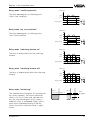
The current output of VEGAMET is set to
4 … 20 mA. By pushing [+] or [–] and [OK]
you can set the output to the following values:
0/20 mA, 20/4 mA and 20/0 mA.
The graphics on the following page show the
behaviour of the relay outputs and LEDs
depending on the level.
Beside the preadjustment (0/10 V), the following options are available for the voltage output: 10/2 V, 10/0 V and 2/10 V.
As a factory setting, the relay outputs are set
to mode "Overfill protection" (mode A). By
pushing [+] or [–] and [OK] you can assign
the mode "Dry run protection" (mode B)
separately for each relay output. In the next
menu items you can determine the upper and
lower switching points for the set mode.
24
VEGAMET 514
Settings in the "reduced menu"
Overfill protection
6.7 Simulation
Parameter
TAGNo. 1
%
xx,x
High
Meas.
value
indication
Low
t
dbz
Relay output
The relay of relay output 1 deenergises at
switching point "High" (safe switching condition).
Param.
TAGNo. 1
Adjustment
Signal
conditioning
Outputs
Simulation
Simulation
Now!
OK ?
Dry run protection
Parameter
Simulation
%
xx,x
High
Low
t
dbz
Relay output
The relay of relay output 1 deenergises at
switching point "Low" (safe switching condition).
VEGAMET 514
To check outputs and connected instruments,
you can adjust any individual percentage
value with the keys [+] and [–] in this menu
item. Initial point is always the actual measured value. The indicated value flashes when
simulation is activated. 15 minutes after
setting the simulated value, the simulation
automatically terminates and resets to meas.
value indication.
25
Settings in the "reduced menu"
6.8 Password, language, default, reset, menu mode
TAGNo. 1
%
xx,x
Param.
TAGNo. 1
Meas.
value
indication
Configuration
Add'l
functiond
Password
off
on
Language
English
French
German
etc.
TAG 1
to de
fault
Reset
TAG 1
Reset
OK ?
Delete
TAG
1?
Reset
Now!
OK ?
Reset
OK ?
Menu
mode
Reduced
Extended
Reset
Now!
OK ?
Password
Default
You have the possibility to protect VEGAMET
514 against unauthorised adjustment or
adjustment by mistake. Activate in the menu
"Password" the option "on" (with keys [+], [–]
and [OK]). Now you can only check the
meas. value on the display. You can still
reach any menu item with the arrow and OK
keys, but as soon as you want to modify an
adjustment, you are asked for the password.
Enter the figure "513" (with the keys [+], [–]
and [OK]), to carry out the adjustment. One
single input of the password is sufficient to
open all protected menu items.
In the menu item "TAG 1 to default" you reset
all settings concerning measurement loop 1
to default. If, for example, you have changed
the name of the measurement loop to "Silo 5",
after the reset the name is again "TAG-No. 1".
Also all adjustment values that you have
entered for measurement loop 1 are now
reset to default.
Language
In the menu item "Language" you can choose
a language other than German such as English, French etc. as menu language (with
keys [+], [–] and [OK]).
26
Reset TAG 1
With "Reset TAG 1" the measurement loop
configuration will be deleted. This function
must be carried out if you want to change the
applied measuring technology (e.g. capacitive instead of hydrostatic).
Menu mode
The menu modes "Reduced" and "Extended"
are available. With the keys [+], [–] and [OK]
you choose the required menu mode. The
menu schematics of the reduced menu and
the extended menu are shown later in this
operating instruction manual. The factory
setting is "Reduced menu".
VEGAMET 514
Settings in the "extended menu"
7 Settings in the "extended menu"
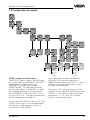
7.1 Configuration of measurement loop
TAG No. 1
%
xx,x
Param.
TAGNo. 1
Configuration
Config
inputs
Config
meas.
loop
TAG 1
Level
Application
Level
0/4-20mA
Gauge
Pressure
Sensor
type
Hydrostatic
Mode
Option
Standard
no
option
capacitive DifVEGADIF ference
VEGABAR
Offset cor.
Real value
cor.
Sensity
cor.
DK cor.
The measurement loop configuration is normally already done at the factory. Should a
fundamental modification of the measurement
loop configuration be necessary, a "Reset to
single measurement" must first be carried out
(in the menu "Additional functions", "Reset
VEGAMET"). Only then can you modify the
adjustments in the menu items Application,
Sensor type, Mode and Option. You should,
therefore, work on the individual menu items
in the given sequence. The selection or adjustment possibilities always depend on the
adjustment in the previous menu item. If, for
example, in the menu item Application "Level"
is adjusted, the sensor mode that is suitable
for level detection can be selected in the
menu item "Sensor type".
As soon as you have carried out and confirmed an adjustment in the menu item "Option", the following message appears on the
display "TAG being created!".
VEGAMET 514
Sensor
coordination
Position A
Input1
TAG
name
TAG No. 1
Position D
Input4
Fault
signal
Tare
Monitoring
Input
from
undefined
Input4
Input
from
undefined
on
off
PositionE
Input4
Input4
You choose the application 4/20 mA when
you want to connect a sensor of another
manufacturer to the VEGAMET.
In the following illustrations, further application modes are shown. In addition, you will
see there which adjustments you have to
carry out in the menu items "Sensor type" and
"Mode".
The menu item "Position D" only appears if in
the menu item "Option" either "Offset correction" or "Real value correction" has been set.
The menu item "Position E" only appears if in
the menu item "Option" either "Density
correction" or "DK correction" has been set.
27
Settings in the "extended menu"
In the menu items "Pos. D" and "Pos. E" you
can specify if input 4 is to used for one of the
stated correction modes (input 4 is the correction signal input on terminals 22d and
24d). You then have to enter a value at which
the correction should be carried out under
"Parameter adjustment" –– "Special funct." in
the menu items "Real value correc. at…" or
"Density correc. at…".
In the menu item "TAG name" you can assign
an individual name to the measurement loop.
If you choose "Fault signal off", the fail-safe
relay and the failure LED on the front plate will
be nonoperable. For a description of the
correction modes, see the following pages.
Note!
Input 4 can also be used for Tare and
Monitoring. However, it is not possible to use
it at the same time for taring, monitoring and,
for example, density correction!
Level measurement
TAG 1
Level
Application
Level
Pos. A
Sensor
type
Hydrostatic
Mode
Option
Standard
no
option
Capacitive
VEGABAR
VEGADIF
Sensor
coordination
Pos. A
Position A
Input1
Level measurement
Gauge measurement
TAG 1
Gauge
Application
Gauge
Pos. A
Sensor
type
Hydrostatic
Mode
Option
Standard
no
option
Sensor
coordination
Position A
Input1
28
Gauge measurement
VEGAMET 514
Settings in the "extended menu"
Process pressure measurement
TAG 1
Process
pres.
Pos. A
Pos. A
Application
Pressure
Sensor
type
VEGABAR
Mode
Option
Standard
no
option
Sensor
coordination
VEGADIF
Position A
Input1
Process pressure measurement
Differential pressure measurement
TAG 1
Pressure
diff.
Application
Pressure
Pos. A
Sensor
type
VEGADIF
Mode
Option
Difference
no
option
Sensor
coordination
VEGABAR
Position A
Input1
Differential pressure measurement
Level measurement with offset correction
TAG 1
Level
Application
Level
Sensor
type
Hydrostatic
Capacitive
VEGABAR
VEGADIF
Mode
Option
Standard
Offset
corr.
Sensor
coordination
Pos. A
Pos. D
Position A
Input1
Position B
Input4
Level measurement with offset
correction
Pos. A: Continuous sensor to input 1
Pos. D, Pos. E: Level switch to input 4
(correction input)
VEGAMET 514
29
Settings in the "extended menu"
Level measurement with real value correction
TAG 1
Level
Application
Level
Sensor
type
Hydrostatic
Mode
Standard
Option
Real
value
corr.
Sensor
coordination
Pos. D
Pos. A
Capacitive
VEGABAR
VEGADIF
Position A
Input1
Position D
Input4
Level measurement with real value
correction
Level measurement with density correction
TAG 1
Level
Application
Level
Sensor
type
Hydrostatic
Mode
Option
Standard
Density
corr.
Sensor
coordination
Pos. E
Pos. A
VEGABAR
VEGADIF
Position A
Input1
Position E
Input4
Level measurement with density
correction
Level measurement with DK correction
TAG 1
Level
Application
Level
Pos. A
Sensor
type
Capacitive
Mode
Option
Standard
DKcorr.
Pos. E
Sensor
coordination
Position A
Input1
Position E
Input4
Level measurement with DK correction
Pos. A: Continuous sensor to input 1
Pos. D, Pos. E: Level switch to input 4
(correction input)
30
VEGAMET 514
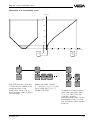
Settings in the "extended menu"
Offset correction
- with unpressurized sensor
- parallel shift of the
adjustement characteristics
actual measured value
in %
incorrect course of measured values
Measured value too low
100%
Measured value too high
Pos. A
0
0
Pos. D
100%
corrected measured value e.g. 0 %
Offset correction
Real value correction
- with a given percentage
value
- parallel shift of the
adjustement characteristics
actual measured value
in %
incorrect course of measured values
Measured value too low
100%
Measured value too high
Pos. D
20
0
0 20
100%
corrected measured value e.g. 20 %
Pos. A
Real value correction
Density correction
- only in conjunction with
hydrostatic pressure
transmitters
- slope correction of the
adjustment characteristics
incorrect course of measured values
actual measured value
in %
smaller density,
measured value too low
100%
higher density,
measured value too high
Pos. E
40
0
0
40
100%
corrected measured value e.g. 40 %
Pos. A
Density correction
DK-correction
- εr -correction
- only in conjunction with
capacitive measuring
probes
- slope correction of the
adjustment characteristics
incorrect course of measured
values
Dielectric constant too small,
Measured value too low
actual measured value
in %Pos. A
100%
Dielectric constant too large,
Measured value too high
Pos. E
40
0
0
40
100%
corrected measured value e.g. 40 %
DK-correction
VEGAMET 514
31
Settings in the "extended menu"
• Choose in the menu item "Input from"
(under the menu item "Tare") input 4.
7.2 Tare
With the function "Tare" a measured value
beginning at 0 % is created from the actual
measured value. The tare function can be
started via a key connected to correction
signal input 4.
Meas. values in %
tared course
Param.
TAGNo. 1
actual course
100%
Adjustment
Key
40
0
40
100%
actual measured values
tared measured values
The following steps are necessary to activate
the tare:
• Connect a key (closer) to input 4.
TAG No. 1
%
xx,x
Param.
TAGNo. 1
TAG No. 1
%
xx,x
Signal
conditioning
Outputs
Current
outputs
Volt
outputs
Volt
output
1
prop.
to
Percent
Unit
Volume
Tare
V%
Tare
%
• Assign the tared values in the menu item
"Unit" to the requested output (e.g. current,
volt, DIS, PC/DCS output, MET indication).
Configuration
Config
inputs
If you want to delete the tare function, you
first have to cancel the tare in the menu item
"Unit". Then you have to cancel the allocation
of the correction input (input 4) under the
menu item "Tare".
Config
meas.
loop
TAG 1
Level
Application
Tare
Level
Input
from
Input4
32
VEGAMET 514
Settings in the "extended menu"
7.3 Monitoring
To activate monitoring, the following
prerequirements must be met:
TAG No. 1
%
xx,x
Param.
TAGNo. 1
TAG No. 1
%
xx,x
Param.
TAGNo. 1
Adjustment
Configuration
Config
inputs
Signal
conditioning
Volt
outputs
Current
outputs
Config
meas.
loop
Relay
outputs
Relay
output
1
TAG 1
Level
Application
Outputs
Monitoring
Level
Input
from
Input4
• Choose in the menu item "Input from"
(under the menu item "Monitoring") input
4.
• Connect a key switch (opener) to input 4.
prop.
to
Percent
Unit
0,0%
Mode
(Monitoring)
Monitoring
Low &
High
Low
High
%
5,0
%
5,0
• Choose in the menu range "Parameter
adjustment relay outputs" in the menu
item "Mode" the mode "Monitoring" for the
selected relay.
The selected relay becomes energised. By
pushing the key switch (opener opens), the
actual measured value is first of all frozen
and, derived from this, the relay deenergises
if this value is underrun (Low) or exceeded
(High). After a reset and a repeated pushing
of the keyswitch, the actual measured value
is again frozen.
Meas.
>55 %
value 50 % High 5 %
Low –5 %
<45%
Relay
deenergises
If the monitoring function should be cancelled, first of all the monitoring must be cancelled in the menu item "Mode". Then the
allocation of the correction input (input 4)
must be cancelled under the menu item
"Monitoring".
VEGAMET 514
33
Settings in the "extended menu"
7.4 Configuration of inputs
TAG No. 1
%
xx,x
Param.
TAGNo. 1
Configuration
Config
inputs
Input no. 1: VBUS input (measured value)
Input no. 4: Correction input
Input
no. 4
Input
no. 1
Input
from
local
Met
MET02
MET03
MET04
….
Channel no.
S1
Input
undefined
Input1
Input2
Input3
Sensor
characteristics
Min.
meas.
range
0,00
Input
from
local
Met
Max.
meas.
range
1,00
Min.
sensor
value
4,000
Channel no.
K1
Input
undefined
Max.
sensor
value
20,000
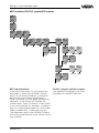
If another VEGAMET has been chosen, the
menu item "Input undefined" appears in which
you can adjust the input number of the other
VEGAMET (see illustration).
Input local MET:
Here you can select another VEGAMET (e.g.
Met 04) and hence determine that the input
signal should not be taken from a directly
connected sensor, but from a VEGAMET
connected over the DISBUS (e.g. VEGAMET
514). The selected VEGAMET number corresponds to the DISBUS address of the instrument (see chapter 4.1).
The menu items "Min. meas. range" and "Max.
meas. range" are only visible with hydrostatic
pressure transmitters. Sensor values are
stated in the test certificate of the hydrostatic
pressure transmitter.
DISBUS
100
ESC
100
OK
ESC
OK
CONNECT
on
CONNECT
on
514Ex
514Ex
"local MET"
MET 04
Input 1
34
VEGAMET 514
Settings in the "extended menu"
7.5 Configuration of outputs
TAG No. 1
%
xx,x
Param.
TAGNo. 1
Configuration
Config
inputs
Config
meas.
loop
Config
outputs
Config
current
output
Config
Volt
output
Current
1 to
TAG No. 1
Volt1
to
TAG No. 1
----
----
Config
PC/
PLC
output
Config
relay
output
Operating
relay
Fail
safe
relay
PC/PLC
meas.
values
Relay
PLC 1
to
TAG No. 1
Standard
Config
VEGADIS
DIS 2
to
DIS 3
to
----
----
DIS 1
to
TAG No. 1
---PC/PLC
relay
status
off
PC/PLC
input
status
off
PLC 2
to
PLC 3
to
----
----
---Rel. 1
to
TAG No. 1
----
PC/PLC output and DIS output:
The PC/PLC signal as well as the DIS signal
are transmitted via the DISBUS. The PC/PLC
output delivers output signals from
VEGAMET to an interface converter
VEGACOM 557. This interface converter
transfers the signals of VEGAMET via different standard protocols to connected systems (DCS/PLC). In the menu items "PLC 1
to" up to "PLC C to…" the measurement loop
can be allocated or switched off.
Rel. 1
Input
Standard
Hold
function
Reset of
alarm
function
undefined
Input4
Rel. 2
to
TAG No. 1
----
Rel. 2
Standard
Hold
function
Reset of
alarm
function
Input
undefined
Input4
Up to three external indicating elements
(VEGADIS 174) can be connected to
DISBUS. In the menu items "DIS 1 to…" up to
"DIS 3 to–" the measurement loop can be
allocated or switched off.
The current, volt and relay outputs are allocated as factory setting to measurement loop
"TAG-No. 1". All outputs can be switched off
individually (----), i.e., they will no longer
access a measurement loop.
In the menu items "PC/PLC relay status" and
"PC/PLC input status" it can be determined
that the relay mode and input status are
transmitted via the DISBUS.
VEGAMET 514
35
Settings in the "extended menu"
Relay outputs
A hold function or a function for reset of alarm
functions can be allocated to each operating
relay. In this case, the menu item "Input undefined" appears. There "Input 4" (correction
input) can be assigned to the relay. For a
description of the relay functions, see the
drawing.
Hold function
Parameter
High
Low
Key
t
dbz
Relay output
Reset of alarm functions
Parameter
High
Low
Key
t
dbz
Relay output
The relay modes "Hold function" and "Reset of
alarm functions" are configured as described
above and are each activated by an external
signal (correction signal input).
36
VEGAMET 514
Settings in the "extended menu"
7.6 Adjustment
TAG No. 1
%
xx,x
Param.
TAGNo. 1
Adjustment
Signal
conditioning
Scaling
Lin.
curve
linear
with
medium
Minadjust
at %
0,0
Integr
ation
time s
0
Density
in
Kg/dm3
1,000
DK
value
(Er)
81,00
without
medium
Maxadjust
at %
100,0
Adjustment
Offset
correction
mA
0%
at
mA
4,000
100%
at
mA
20,000
Sensor
unpressur'd?
OK ?
Offset
corr.
Now!
OK ?
The adjustment with medium corresponds
to the procedure in the reduced menu (see
appropriate chapter).
- if the medium is changed later on (medium
with another density value or DK value)
and no new adjustment can be made
or
- if the MET indication and the DIS outputs
relate to height in meters,
please note the following:
In applications with hydrostatic pressure
transmitters, the adjusted density value must
correspond to the value of the medium. In
applications with capacitive electrodes, the
adjusted DK value must correspond to the
value of the medium (water has a density of
1.0 kg/dm3 and a DK value of 81.00).
VEGAMET 514
For the adjustment without medium, two
anticipated values for level, gauge, etc.
corresponding to 0% and 100% must be
entered.
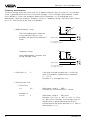
The menu item "Offset correction" is opened
when hydrostatic pressure transmitters are
connected. The offset correction should be
carried out after installation of the sensor as
the sensor values can differ slightly due to
different installation positions (vertical or
horizontal installations). With the offset correction, the meas. data of the unpressurised
sensor (vessel empty) are detected as correction values and taken into account in all
subsequent measurements.
37
Settings in the "extended menu"
7.7 Conditioning
TAG No. 1
%
xx,x
Param.
TAGNo. 1
Adjustment
Signal
conditioning
Scale
Integr
ation
time s
0
linear
cylindrical tank
etc.
Density DK
value
in
(Er)
Kg/dm3
81,00
1,000
0%
corresponds
0
100%
corresponds
1000
prop.
to
undefined
Lin.
curve
Decimal
point
888,8
Meas.
value
limitation
Unit
––
negative
values
yes
Failure
mode
Stan
dard
>110%
The menu items "Scaling" and "Integration
time" correspond to the menu items in the
"reduced menu" (see appropriate chapter).
The menu items "Density…" or "DK value…"
are optionally displayed when under "Configuration measurement loop" the appropriate
sensor type has been selected. The density
or DK value must, before adjustment with
medium, be so adjusted that it corresponds
to the value of the medium (see also chapter
"7.6 Adjustment").
The conditioning of VEGAMET can be
adapted to different vessel forms. The following linearisation curves are available:
- linear (factory setting)
- horiz. cylindrical tank
- spherical tank
- Lin-curve 1
- Lin-curve 2
- Lin-curve 3
Lin-curves 1 … 3 can be edited by the
user (see appropriate chapter).
38
After a scaling or linearisation, the required
output must be assigned to the scaled or
linearised value (menu item "prop. to..." and
"Unit...") under the menu "Parameter adjustment outputs".
Under Meas. value limitation you can exclude negative values.
Failure mode Standard
means that at a sensor current of 3.6 mA or
21 mA the fail-safe relay responds.
Failure mode >110%
also generates a fault signal when a meas.
value of more than 110 % or less than -10 %
is reached.
VEGAMET 514
Settings in the "extended menu"
7.8 Parameter adjustment of outputs
Current outputs/Volt of outputs
TAG No. 1
%
xx,x
Param.
TAGNo. 1
Adjustment
Signal
conditioning
Outputs
Current
outputs
Volt
outputs
Current
output
1
Volt
output
1
prop.
to
Percent
Volume
prop.
to
Percent
Unit
Volume
TARE%
Unit
Current
output
Volt
at
100%
10,000
Failure
mode
10/2V
10/0V
2/10V
free
0,0
..10,0
0,0
..10,0
11V
-0%
100%
Current
at
0%
4,000
Current
at
100%
20,000
Failure
mode
0,0
..20,0
22mA
-0%
100%
0/10V
0,0%
TARE%
Volt
at
0%
0,000
Volt
output
0,0%
0/20mA
20/4mA
20/0mA
free
0,0
..20,0
In the menu item "prop. to" you can choose
between percent and volume. "Prop. to volume" is then useful when under "Signal conditioning - Linearisation curves", for example, a
spherical tank or an individually defined
linearisation curve is selected. The output
current or the output voltage is then proportional to the volume of the tank contents.
Unit:
Selection list dependent on the choice in the
previous menu item "prop. to" (see chapter "8
Measuring results and units").
Volt output/Current output:
If "free" is chosen, the following (light grey)
menu items appear:
VEGAMET 514
0mA
0V
Volt
limitation
on
off
Current
limitation
on
off
- Volt at 0 %/100 %:
Individual voltage values between 0 V and
+10 V can be adjusted.
- Current at 0 %/100 %:
Individual current values between 0 mA
and +20 mA can be adjusted.
Failure mode:
The height of the output current/output voltage in case of failure is set here. If "--" is
chosen, the actual value is maintained.
Volt limitation/Current limitation on:
Voltage/current remain within the values
which are given in the menu item voltage
output/current output.
39
Settings in the "extended menu"
Relay outputs
TAG No. 1
%
xx,x
Param.
TAGNo. 1
Adjustment
Signal
conditioning
Outputs
Current
outputs
Relay
output
1
Volt
outputs
Relay
outputs
Relay
output
2
like relay output 1
prop.
to
Percent
Volume
Height
Pressure
Unit
0,0%
0,00 %
Tare %
MoniLow
Mode
toring
OverLow &
fill
%
High
protec.
0,0
Dry run protec.
Switching window on
Switching window off
Tendency rising
Tendency falling
(monitoring)
High
%
100,0
In the menu item "prop. to" you choose a
parameter that the relay will react to. You can
choose between percent and volume ("prop.
to volume" is useful when under "Conditioning
- Linearisation curves", for example, a spherical tank or a user programmable lin. curve is
chosen). In the next menu item you can
choose the suitable Unit. In the menu item
"Mode", the mode of the relay can be chosen.
The individual relay modes are described on
the following pages.
If mode "Tendency rising" or "Tendency
falling" is selected, the menu items "Deviation", "Dev. per time", "Cycle time" and
"Number of cycles" appear.
40
Deviation
s
1,0
Deviation
per
time
Failure
mode
Add'l
functions
off
hold
Switching
delay
Scan
time
s
1
Number t
of
scan
10
on
t off
s
0
s
0
With all other modes, the menu items "Low"
and "High" appear. There you can determine
the switching points for the relay.
The menu item "Failure mode" always appears. "Failure mode off" causes the relay to
deenergise when a failure (e.g. sensor
shortcircuit) occurs. "Failure mode hold"
causes the actual relay status to be
maintained when a failure occurs.
Under "Add’l functions", you can adjust a
switch on delay (t on) and a switch off delay
(t off) of the relay to a max. of 600 s (with the
relay modes "Tendency rising" or "Tendency
falling" no switching delay can be set).
VEGAMET 514
Settings in the "extended menu"
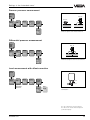
Relay mode "overfill protection"
Parameter
The relay deenergises at switching point
"High" (safe condition).
High
Low
dbz
t
Relay output
Relay mode "dry run protection"
Parameter
The relay deenergises at switching point
"Low" (safe condition).
High
Low
t
dbz
t
dbz
t
dbz
Relay output
Relay mode "switching window on"
Parameter
The relay is energised within the switching
window.
High
Low
Relay output
Relay mode "switching window off"
The relay is deenergised within the switching
window.
Parameter
High
Low
Relay output
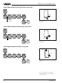
Relay mode "monitoring"
The selected relay energises. By pushing the
key switch (opener), the actual measured
value is first of all frozen and, derived from
this, the relay deenergises of this value is
underrun (Low) or exceeded (High). After a
reset and a repeated pushing of the key
switch, the actual measured value is again
frozen.
VEGAMET 514
Meas.
>55 %
value 50 % High 5 %
Low –5 %
Relay
deenergised
<45%
41
Settings in the "extended menu"
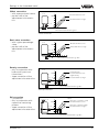
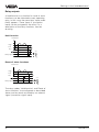
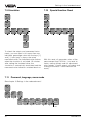
Tendency determination
The level change within the cycle time (ta) is determined and, after all cycles (n), an average
value is generated from the sum of the level changes. If this average value exceeds a previously defined % value, the tendency determination responds, i.e. an energised relay
deenergises. With the selection "Tendency rising" or "Tendency falling", the menu items "Deviation in %" and "Deviation per time" are opened.
%
t ges.
ta
– – Mode Tendency rising
The relay deenergises when the
rising average value of "t tot."
exceeds the previously defined %
value.
t
1
2
3
4 n=4
dbz
Relay output
ta = cycle time
n = number of cycles
%
Tendency falling
t ges.
ta
same dependence, however with
falling average value
t
1
2
3
4 n=4
dbz
Relay output
ta = cycle time
n = number of cycles
– – Deviation in %
2
If the level change exceeds the % value set
here, the tendency determination responds.
0 … 110 %
Example 2 % (change) per t tot.
– – Cycle time
in s
60
Adjustment range 0 … 999 s
Example: 60 s correspond to 1 minute
– – Number of
cycles
4
Adjustment range 0 … 99 cycles
Example: t tot = ta • n = 60 • 4 = 240 s = 4 min,
i.e. after every 4 minutes, the average value of
the deviation is generated and the result is
compared with the given deviation in %, here in
the example = 2 %
– – Deviation per time
42
VEGAMET 514
Settings in the "extended menu"
MET indication/PC/PLC outputs/DIS outputs
TAG No. 1
%
xx,x
Param.
TAGNo. 1
Adjustment
Signal
conditioning
Outputs
Current
outputs
Volt
outputs
Relay
outputs
MET
display
prop.
to
Percent
PC/PLC
outputs
Unit
DIS
outputs
DIS
output
1
DIS
output
2
prop.
to
Percent
scaled
Height
…
Unit
DIS
output
3
0,0%
scaled
Height
…
like DIS output 1
PC/PLC
output 1
prop.
to
Percent
Unit
0,0%
PLC
output 2
PLC
output 3
like PLC output 1
0,0%
scaled
Height
…
MET indication/Unit:
In the menu item "prop. to" you choose the
parameter to which the VEGAMET display
reacts (if you have carried out a scaling under the menu item "Signal conditioning",
"prop. to scaled" will have been automatically
adjusted, i.e. the display will indicate the
scaled value). "Prop. to volume" is then useful
if you have selected, for example, a spherical
tank or a user-programmable lin. curve under
"Signal conditioning - Linearisation curves".
The indicated value of the VEGAMET display
then reacts proportionally to the volume of the
tank contents.
VEGAMET 514
PC/PLC outputs and DIS outputs:
Are adjusted according to the same
procedure as the MET indication.
43
Settings in the "extended menu"
7.9 Simulation
7.10 Special function: Reset
TAG No. 1
%
xx,x
TAG No. 1
%
xx,x
Param.
TAGNo. 1
Param.
TAGNo. 1
Adjustment
Signal
conditioning
Outputs
Simulation
Adjustment
Signal
conditioning
Outputs
Simulation
Special
functions
Simulation
Now!
OK?
Reset
Level
Simulation
%
XX,X
Reset
OK ?
To check the outputs and connected instruments, you can adjust in this menu item any
individual percentage value with the keys [+]
and [–]. Initial point is always the actual
measured value. The indicated value flashes
when the simulation is activated. 15 minutes
after setting the simulated value, the
simulation is automatically terminated and the
measured value indication switched back on.
Reset
Now!
OK ?
With this reset, all parameter values of the
measurement loop TAG-No. 1 are reset to
factory setting (empty and full adjustment,
relay outputs, current output, volt output and
scaling of the meas. value indication are
reset).
7.11 Password, language, menu mode
See chapter "6 Settings in the reduced menu".
TAG No. 1
%
Param.
TAGNo. 1
Configuration
Add'l
functions
Password
off
Edit
lin.
curve
Info
Language
English
Reset
VEGAMET
Service
Menu
mode
Extended
Reduced
44
VEGAMET 514
Settings in the "extended menu"
7.12 Special function: Manual correction
TAG Nr. 1
%
xx,x
Param.
TAGNr. 1
Adjustment
Signal
conditioning
Outputs
Simulation
Special
functions
Simulation
Now!
OK?
Reset
Level
Simulation
%
XX,X
Real
value
corr.
at % 0
Density
corr.
at%
50,0
DK
corr.
at %
50,0
1)
1)
1)
Reset
OK ?
Reset
Now!
Manual
corr.
Offset
correction
Real
value
corr.
Offset
correction
OK?
Real
value
corr.
OK?
Correction
Now!
OK ?
Correction
%
0,0
OK ?
1)
This menu item only appears if with the measurement loop configuration a correction mode was
adjusted. Then, the percentage value at which the
automatic correction occurs must be set here.
Manual offset correction
(only with hydrostatic pressure transmitters)
This correction can be carried out to
compensate changes of the sensor values
due to ageing. In oder to do this, the sensor
must be in an unpressurized condition
(empty vessel).
VEGAMET 514
Correction
Now !
OK ?
Manual real value correction
In the menu item "Correction % 0.0" you can
enter a percentage value which corresponds
to the actual level.
45
Settings in the "extended menu"
7.13 Linearisation curves
TAG No. 1
%
xx,x
Param.
TAGNo. 1
Configuration
Add'l
functions
Password
Edit
lin.
curve
off
Lin.
curve1
Lin.
curve2
Lin.
curve3
like LIN curve 1
Add
lin.
point
Edit
lin.
curve 1
x
x 0 %
0,0
y 0 V%
0,0
%
0,0
y V%
0,0
Delete
lin.
point
x 1 %
100,0
y 1 V%
100,0
x 2 %
100,0
y 2 V%
100,0
x 32 %
100,0
y 32V%
100,0
Index marker number
(0…32)
x 0,0
y 0,0
delete
x 100,0
y 100,0
delete
Delete
now?
Delete
now?
Linearisation curve 1 … 3
A linearisation curve is created with a number
of index markers and their value pairs. A
value pair consists of a value for level percent (X %) and a value for volume percent
(Y V %). Up to max. 32 index markers can
be included. A linearisation curve can be
terminated after any individual number of
index markers. The signal conditioning instrument terminates the linearisation curve automatically with the values X = 100 % and Y
= 100 %.
The data for the value pairs can be determined by incremental filling or can be taken
from a table of values provided by the vessel
manufacturer.
An Example of incremental filling
Initial situation:
- you have already carried out the 0% and
100% adjustment
- the total volume of the vessel is known to
you, for example 300 m3
- the increment or gauging volume in this
example was determined at 15 m 3
46
1st index marker
- fill the vessel with the liquid quantity of the
gauging volume of 15 m3
- the value for level percent is indicated on
VEGAMET, transfer this value into the linearity protocol, column X %
- the value for volume percent must be calculated acc. to the following formula
100 % x gauging volume
Y 1 V = ––––––––––––––––––––––––
total volume
100 % x 15 m3
= ––––––––––––––– = 5 %
300 m3
Transfer this value also into the linearity
protocol, column Y V %.
2nd index marker etc.
In addition, see the following illustration.
VEGAMET 514
Settings in the "extended menu"
Illustration of a linearisation curve
X (in %)
100
80
60
40
20
0
20
40
60
80
%
12,0
Y1 V %
5,0
Add lin.
point
Edit
lin.
curve 1
x
x 0 %
0,0
y 0 V%
0,0
%
0,0
y V%
0,0
With [OK] the new value pair
is automatically added to the
correct position in the
linearisation curve. The already present index markers
are re-sorted.
VEGAMET 514
100 V (in %)
X32 %
100,0
Y32V %
100,0
X1
Delete
lin.
point
x 1 %
100,0
y 1 V%
100,0
x 2 %
100,0
y 2 V%
100,0
Select the index markers
1 … 32 with [–>] or [<–], edit
the Y value with [+] or [–],
accept with [OK].
x 0,0
y 0,0
delete
x100,0
y100,0
delete
Delete
Now?
Delete
Now?
To delete the index markers,
select the value pairs with [–
>] or [<–]. With [OK] the
value pair and the
corresponding index marker
are deleted in the lin. curve.
The remaining index markers
move up.
47
Settings in the "extended menu"
Linearity measurement protocol
A linearisation curve is entered in the menu item "Add. lin. point".
Linearisation curve 1
Index marker
no.
Value pair
X%
YV%
Linearisation curve 2
Index marker
no.
Value pair
X%
YV%
Linearisation curve 3
Index marker
no.
1
1
1
2
2
2
3
3
3
4
4
4
5
5
5
6
6
6
7
7
7
8
8
8
9
9
9
10
10
10
11
11
11
12
12
12
13
13
13
14
14
14
15
15
15
16
16
16
17
17
17
18
18
18
19
19
19
20
20
20
21
21
21
22
22
22
23
23
23
24
24
24
25
25
25
26
26
26
27
27
27
28
28
28
29
29
29
29
29
29
30
30
30
31
31
31
32
32
32
Value pair
X%
YV%
Note
Date
Name
48
VEGAMET 514
Settings in the "extended menu"
7.14 Info
TAG No. 1
%
xx,x
Param.
TAGNo. 1
Configuration
Add'l
functions
Password
Lin.
curve
Info
off
Input
info
VEGAMET
info
Type
MET514
Input1
Sensor
type
Hydrostatic
Program
info
Meas.
loop
info
Program
info
xxxxxx
TAG 1
TAG No. 1
Serial
number
xxxx
xxxx
Minadjust
at %
0,0
Minadjust
bar
0,000
Maxadjust
at %
100,0
Maxadjust
bar
1,000
Instr.
addr.
1
Softw.
vers.
V1.13
06
Softw.
date
Param.
vers.
47/97
5
Parameter
Level
Input4
Sensor
type
Vibration
Input
from
local
MET
Input
from
local
MET
Channel
no.
S1
Channel
no.
Input
undefined
Actual
switch
status
K1
Input
undefined
Sensor
characteristics
Actual
sensor
value
xx,xxx
Min.
range
Max.
range
0,00
1,00
Min.
sensor
value
4,000
Max.
sensor
value
20,000
All menu items under "Info" only have display
function.
VEGAMET 514
49
Settings in the "extended menu"
7.15 Reset VEGAMET
TAG No. 1
%
xx,x
Param.
TAGNo. 1
Configuration
Add'l
functions
Password
off
Lin.curve
Info
Language
English
Reset
VEGAMET
Reset
configuration
Reset
sensor
values
Reset
lin.curves
TAG 1
to de
fault
to
single
meas.
Reset
input1
Reset
lin.curve1
Reset
lin.curve2
Reset
lin.curve3
Reset
all
curves
Reset
Reset
TAG1
Reset
Reset
Reset
Reset
Delete
all
curves?
OK?
OK?
OK?
OK?
Reset
now!
Reset
now!
Reset
now!
Reset
now!
Reset
OK?
OK?
OK?
OK?
OK?
OK?
Reset
now!
Delete
TAG1?
OK?
Reset
Reset
now!
OK?
OK?
Reset
now!
OK?
With the function "TAG 1 to default" you reset
the whole configuration and parameter adjustment to factory setting. However, the
basic configuration remains, e.g. "Level
measurement/Hydrostatic".
With the function "Reset TAG 1" the basic
configuration is also deleted. Then the measurement loop must be created completely a
new (config. meas. loop).
With the function "Reset lin-curves" you can
delete your manually edited linearisation
curves.
With "Reset all curves" you delete all together,
with "Reset lin-curve 1" you always delete
only one curve.
The three pre-programmed lin-curves "linear,
horiz. cylindrical tank, spherical tank" cannot
be deleted.
With "Reset sensor values", the adjusted
sensor data of the connected sensor are
deleted.
50
VEGAMET 514
Measuring results and units
8 Measured quantity and units
With all outputs and with scaling, you find the
menu items "prop. to" and "Unit". Here you
can choose the measured quantity and the
suitable unit. The list of the units depends on
the selected measured quantity. In the table,
the available units are listed.
Scaling
prop. to
Unit
Percent
%
Volume
m3
hl
l
gal
V%
ft3
in3
Height
m
dm
cm
mm
yd
ft
in
Pressure
bar
mbar
psi
hPa
Mass
kg
t
lb
Density
kg/dm3
g/cm3
Current/Volt output
prop. to
Unit
Percent
0,0 %
Tare %
Volume
V%
Tare V %
VEGADIS/PLC/MET indication
prop. to
Unit
Percent
0,0 %
0,00 %
Tare %
Volume
V%
Tare V %
Height
m
Pressure
bar
scaled
scaled
Tare scaled
Relay outputs
prop. to
Unit
Percent
0,0 %
Tare %
Volume
V%
Tare V %
Height
m
Pressure
bar
VEGAMET 514
51
Diagnostics
9 Diagnostics
9.1 Maintenance
Configuration
The instrument is maintenance-free.
9.2 Simulation
Note
When the simulation is activated, the entire
display flashes. The measured data
delivered by the sensors are not released for
processing; you should, therefore, quit this
menu item as soon as possible. After 15
minutes there is an automatic reset to meas.
value indication.
For each individual measurement loop, you
can determine if a fault signal should be triggered or not. See menu "Configuration
measurement loop", menu item "Fault signal".
Parameter adjustment
In the menu item "Failure mode" you can determine individually for each measurement
loop whether and how an exceeding of the
measuring range should trigger a fault signal.
9.4 Repair
9.3 Fault signal
The signal conditioning instrument and the
connected sensor are permanently monitored during operation. During the parameter
adjustment, the adjusted values are checked
for plausibility. In both cases a fault signal
can be triggered by irregularities.
For safety and guarantee reasons, repair on
the instrument must only be carried out by
VEGA staff.
In case of defect, please return the affected
instrument with a short description of the fault
to our repair department.
In case of failure, an error code is displayed
(only within the meas. value indication), the
fail-safe relay deenergises, the signal lamp
lights and the outputs react according to the
preadjusted condition.
The error codes are listed in section "9.5
Error codes" on the following pages.
The diagnosis info is transmitted as a
scrolling text info.
52
VEGAMET 514
Diagnostics
9.5 Error codes
Error code
Meaning
E004
This operation is not supported by the instrument (different software versions).
You have tried to activate a function with a newer software version of VEGA
Visual Operating in an instrument with older software version. However, the
instrument cannot support this operation.
Have the software of your instrument updated.
E014
Possible short-circuit
Probable reasons:
- short-circuit
- sensor is defective
Check the connection cable and, if necessary, the sensor.
Probably
- an incorrect measuring range has been set on the capacitive electrode.
Adjust a smaller range.
E015
Possible line break
Probable reasons:
- no sensor connected
- line break
- sensor is defective
Check the connection cable and, if necessary, the sensor.
E016
Empty/full adjustment reversed. The values for the empty adjustment are
above the values for the full adjustment. Carry out the adjustment again.
E017
Adjustment span too small. The adjustment values are too close together or are
identical. Carry out the adjustment again.
Probably
- an incorrect measuring range has been set on the capacitive electrode.
Adjust a higher range.
E021
Span of the scaling values too small or values reversed. The scaling values are
too close together or are identical. Please check the scaling.
E022
Scaling span too big.
E027
Actual measured value is less than -10 %.
E028
Actual measured value is more than 110 %.
E031
Same DISBUS address. At least one other instrument with the same DISBUS
address is connected to the DISBUS. Please check the DISBUS address.
E032
Instrument address 0. Instrument address 0 has been set on VEGAMET. With
this address VEGAMET does not participate in the DISBUS communication,
even if the DISBUS is wired. If necessary, modify the instrument address.
VEGAMET 514
53
Diagnostics
Error code
Meaning
E034
Instrument error. A serious error was detected on the instrument (possibly
defective EEPROM). Disconnect voltage and then reconnect (cold start). If the
error is not eliminated, please contact your VEGA agency.
E035
Instrument error. A serious error was detected on the instrument (check sum
error in EPROM). Disconnect voltage and then reconnect (cold start). If the
error is not eliminated, please contact your VEGA agency.
E050
Remote VEGAMET not found. The VEGAMET from which a measured value is
expected cannot be found.
Reasons:
- the remote VEGAMET is not connected
- no VEGAMET with this instrument address connected
- line break (DISBUS)
- shortcircuit (DISBUS)
- the remote VEGAMET is defective
- disrupted communication (DISBUS)
Probably
- failure in the DISBUS transmitter/receiver part of VEGAMET
Please check the instrument address on both VEGAMETs, the connection
cable, the remote VEGAMET and, if necessary, this VEGAMET.
E051
Failure during transmission of measured values via DISBUS. It is not possible
to receive a valid measured value via DISBUS from the remote VEGAMET; the
communication to the remote VEGAMET, however, is okay.
Reason:
- failure on remote VEGAMET
- the input of the remote VEGAMET, which should be transmitted to, is not yet
configured
Please check the remote VEGAMET and, if necessary, its input configuration.
E052
The input number of the VEGAMET from which a measured value is expected
has not yet been assigned.
E053
Span of the sensor characteristics values too small. The sensor characteristics
values are too close together or are identical.
E054
Sensor characteristics values reversed. The min. sensor characteristics value
is higher than the max. sensor characteristics value.
E060
Span of the current output values too small. The values for the current output
are too close togehter or are identical. Please check the adjustment of the
current output.
54
VEGAMET 514
Diagnostics
Error code
Meaning
E061
Span of the voltage output values too small. The values for the voltage output
are too close togehter or are identical. Please check the adjustment of the
voltage output.
E063
Incorrect sensor characteristics values. Please check the sensor
characteristics values
E102
A reset of the configuration was carried out on this VEGAMET via the keyboard.
E110
Switching hysteresis to small. The switching points are too close together or
are identical.
E111
Relay switching points reversed. The relay switching points are reversed with
respect to the selected relay mode.
VEGAMET 514
55
Menu schematics "reduced menu"
10
Menu schematics
10.1
Menu schematic "reduced menu"
TAGNo. 1
%
xx,x
Param.
TAGNo. 1
actual
measured
value
Configuration
Add'l
functions
Password
off
Sensor
type
Hydrostatic
Language
English
TAG
name
TAG No. 1
TAG 1
to de
fault
Reset
TAG 1
Reset
Delete
TAG
1?
Menu
mode
Reduced
OK ?
The sensor type can only be
modified, when a "Reset
TAG 1" has been carried out
first.
Reset
now!
Reset
OK ?
OK ?
Reset
now!
OK ?
Adjustment
Outputs
Signal
conditioning
Scaling
Simulation
Integr
ation
time s
0
Simulation
now!
OK ?
Current
output 1
4/20mA
Volt
output
1
0/10V
Relay
output
1
Relay
output
2
Mode
Overfill
protec
Low
Simulation
%
xx,x
as rel. outp. 1
0%
corresponds
0
with
medium
Minadjust
at %
0,0
56
100%
corresponds
1000
Decimalpoint
888,8
%
0,0
prop. to
Unit
undefined
––
High
%
100,0
without
medium
Maxadjust
at %
100,0
0%
at
mA
4,000
100%
at
mA
20,000
VEGAMET 514
Menu schematics "reduced menu"
ESC
Sensor
mode
Hydrostatic
Bold print/italic is the sensor or
measured value information
which cannot be modified in
this position.
Language
English
In white letters you can see the
parameters which can be modified with the [+] or [–] key and
saved with the [OK] key.
Current at
100%
20,000
Light grey menu items are only
displayed if necessary (depending on the adjustment in
other menu items).
OK
With these keys you move
in the menu field
VEGAMET 514
57
Menu schematic "extended menu"
TAG No. 1
%
xx,x
10.2 Menu schematic "extended menu"
Configuration
Param.
TAGNo. 1
Adjustment
Signal
conditioning
Outputs
Add'l
functions
see following pages
Current
outputs
Volt
outputs
Current
output
1
Volt
output
1
PC/PLC
outpus
MET
display
Relay
outputs
prop.
to
Percent
Unit
PC/PLC
output1
PC/PLC
output2
PC/PLC
output
0,0%
as PLC output1
Relay
output
1
prop.
to
Percent
Unit
Monitoring
Low &
High
Low
0,0%
Mode
Overfill
protec
Volt
at
100%
10,000
Failure
mode
0V
Volt
limitation
on
Failure
mode
Current
limitation
on
Relay
output
2
0,0%
as relay outp. 1
prop.
to
Percent
Scaling
prop.
to
Percent
Unit
Volt
output
0,0%
0/10V
Volt
at
0%
0,000
prop.
to
Percent
Unit
Current
output
Current
at
0%
4,000
Current
at
100%
20,000
Lin.
curve
Integr
ation
time s
0
linear
0%
corresponds
0
with
medium
Minadjust
at %
0,0
Unit
100%
corresponds
1000
0,0%
Decimal
point
888,8
4/20mA
Density
in
Kg/dm3
1,000
DK
value
(Er)
81,00
Meas.
value
limitation
prop.
to
undefined
Unit
negative
values
yes
––
0mA
High
%
0,0
%
100,0
Failure
mode
Stan
dard
without
medium
Maxadjust
at %
100,0
Adjustment
Offset
correction
mA
0%
at
mA
4,000
100%
at
mA
20,000
Sensor
unpressur'd ?
OK ?
Offset
corr.
Now!
OK ?
58
VEGAMET 514
Menu schematic "extended menu"
DIS
outputs
DIS
output1
prop.
to
Percent
Deviation
%
1,0
DIS
output2
DIS
output3
Simulation
Special
funct.
Simulation
now!
OK?
Reset
Level
Simulation
%
XX,X
Reset
as DIS output 1
Unit
Rela
value
corr.%
0
Density
corr.
at %
50,0
DK
corr.
at %
50,0
OK ?
Reset
Now!
0,00%
OK ?
Deviation
per
time
Failure
mode
off
Add'l
functions
Scan
time
s
1
Number
of scan
10
Switching
delay
t
Manual
corr.
Offset
correction
Real
value
corr.
Offset
correction
OK?
Real
value
corr.
OK?
Correction
now!
OK ?
Correction
%
0,0
Correction
now!
OK ?
on
t off
s
0
s
0
ESC
Sensor
type
Hydrostatic
Bold print/italic is the sensor or
measured value information
which cannot be modified in
this position.
Language
English
In white letters you can see the
parameters which can be modified with the [+] or [–] key and
saved with the [OK] key.
Current
at
100%
20,000
Light grey menu items are only
displayed if necessary (depending on the adjustment in
other menu items).
OK
With these keys you move
in the menu field
VEGAMET 514
59
Menu schematic "extended menu"
TAG No. 1
%
xx,x
Param.
TAGNo. 1
Add'l
functions
Configuration
see previous
pages
Config
inputs
see following
pages
Config
meas.
loop
Config
outputs
Config
current
output
Config
Volt
output
Operating
relay
Current1
to
TAG No. 1
Config
VEGADIS
Config
PC/PLC
outputs
Config
relay
output
Fail
safe
relay
PC/PLC
meas.
value
PC/PLC
relay
status
aus
DIS 1
to
TAG No. 1
DIS 2
to
DIS 3
to
----
----
PLC 1
to
TAG No. 1
PLC 2
to
PLC 3
to
Standard
----
----
Rel. 1
to
TAG No. 1
Rel. 1
Input
Rel. 2
Input
Standard
undefined
Rel. 2
to
TAG No. 1
Standard
undefined
Sensor
coordination
TAGname
TAG No. 1
Fault
signal
Tare
Monitoring
Position A
Input1
Position D
Input4
Position E
Input4
Input
from
undefined
Input
from
undefined
Min.
sensor
value
4,000
Max.
sensor
value
20,000
Relay
Volt1
to
TAG No. 1
TAG 1
Level
Mode
Option
Level
Sensor
type
Hydrostatic
Standard
no
option
1)
1)
1)
1)
Application
1) The parameters in these menu items can
only be modified when a "Reset to single
measurement" has been carried out first.
Input
no. 1
Input
from
local
Met
Input
no. 4
Input
from
local
Met
Channel no.
Channel no.
Input
S1
K1
undefined
Input
undefined
Sensor
characteristics
Min.
meas.
range
0,00
60
on
Max.
meas.
range
1,00
VEGAMET 514
Menu schematic "extended menu"
ESC
Sensor
type
Hydrostatic
Bold print/italic is the sensor or
measured value information
which cannot be modified in
this position.
Language
English
In white letters you can see the
parameters which can be modified with the [+] or [–] key and
saved with the [OK] key.
Current
at
100%
20,000
Light grey menu items are only
displayed if necessary (depending on the adjustment in
other menu items).
OK
With these keys you move
in the menu field
VEGAMET 514
61
Menu schematic "extended menu"
TAG No. 1
%
xx,x
Param.
TAGNo. 1
Add't
functions
Configuration
see previous pages
Password
Edit
lin.
curve
Info
Language
English
off
Input
info
VEGAMET
info
Type
MET514
Input1
Input4
Sensor
type
Vibration
Lin.curve1
Sensor
type
Hydrostatic
Input
from
local
MET
Lin.curve2
Lin.curve3
Input
from
local
MET
Program
info
Meas.
loop
info
Program
info
xxxxxx
TAG 1
TAG No. 1
Channel
no.
K1
Channel no.
Input
undefined
S1
Minadjust
bar
0,000
Maxadjust
at %
100,0
Maxadjust
bar
1,000
Instr.
addr.
1
Softw.
vers.
V1.13
06
Softw.
date
Param.
vers.
47/97
5
Serial
number
xxxx
xxxx
Minadjust
at %
0,0
Input
undefined
Parameter
Level
Actual
switch
status
Sensor
characteristics
act.
sensor
value
xx,xxx
Min.
meas.
range
0,00
Max.
meas.
range
1,00
Min.
sensor
value
4,000
Max.
sensor
value
20,000
as LIN-curve 1
Add lin.
point
Edit lin.
curve1
x
x 0 %
0,0
y 0 V%
0,0
%
0,0
y V%
0,0
Delete
lin.
point
x 1 %
100,0
y 1 V%
100,0
x 2 %
100,0
y 2 V%
100,0
x32 %
100,0
y32 V%
100,0
Index marker number (0…32)
62
x 0,0
y 0,0
delete
x100,0
y100,0
delete
Delete
now?
Delete
now?
VEGAMET 514
Menu schematic "extended menu"
Service
Reset
VEGAMET
Reset
configuration
Reset
sensor
values
Reset
lin.
curves
only
accessible
with
password
Menu
mode
Extended
TAG 1
to de
fault
to
single
meas.
Reset
input1
Reset
lin.
curve1
Reset
lin.
curve2
Reset
lin.
curve3
Reset
all
curves
Reset
Reset
TAG1
Reset
Reset
Reset
Reset
Delete
all
curves?
OK?
OK?
OK?
OK?
Reset
now!
Reset
now!
Reset
now!
Reset
now!
OK?
OK?
OK?
OK?
OK?
Reset
now!
Delete
TAG1?
OK?
Reset
OK?
Reset
Reset
now!
OK?
OK?
Reset
now!
OK?
ESC
Sensor
type
Hydrostatic
Bold print/italic is the sensor or
measured value information
which cannot be modified in
this position.
Language
English
In white letters you can see the
parameters which can be modified with the [+] or [–] key and
saved with the [OK] key.
Current at
100%
20,000
Light grey menu items are only
displayed if necessary (depending on the adjustment in
other menu items).
OK
With these keys you move
in the menu field
VEGAMET 514
63
VEGA Grieshaber KG
Am Hohenstein 113
D-77761 Schiltach
Phone
(07836) 50-0
Fax
(07836) 50-201
E-Mail
[email protected]
www.vega.com
Safety information
Note Ex area
Please read this manual carefully, and also take
note of country-specific installation standards
(e.g. the VDE regulations in Germany) as well
as all prevailing safety regulations and accident prevention rules.
For safety and warranty reasons, any internal
work on the instruments, apart from that involved in normal installation and electrical connection, must be carried out only by qualified
VEGA personnel.
Please note the attached safety instructions
containing important information on installation
and operation in Ex areas.
These safety instructions are part of the operating instruction and come with the Ex approved
instruments.
ISO 9001
All statements concerning scope of delivery, application, practical
use and operating conditions of the sensors and processing systems correspond to the latest information at the time of printing.
Technical data to subject to alterations
2.21 851 / 071018