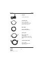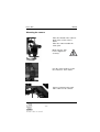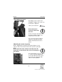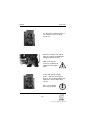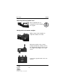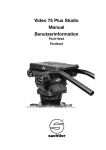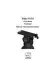
1
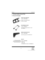
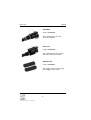
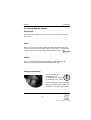
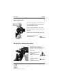
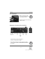
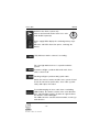
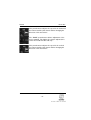
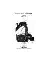
Remote Head REMO ONE
Code 5750
Manual
© by sachtler. All rights reserved
Version: 1.2/09/05
Issue date: September 2005
Order no.: srh20t010a
We want you to receive Sachtler products
that are always state of the art.
Therefore we reserve the right to make changes based on technical advances
sachtler GmbH & Co. KG
Erfurter Strasse 16
Postfach / P.O.BOX 2039
D-85386 Eching
D-85380 Eching
Germany
Germany
Telefon: (+49) 89 32158200
Telefax: (+49) 89 32158227
E-Mail: [email protected]
Homepage: http://www.sachtler.com
Table of contents
Table of Contents
1
General Information .............................................................1
2
Intended use ........................................................................1
3
Symbols used in the User’s Manual ....................................2
4
Safety Instructions................................................................3
5
Remote Option .....................................................................4
5.1
Scope of Supply..........................................................4
5.2
Set up Remote Option ................................................6
6. Remote Head Remo One ..................................................10
6.1
Scope of Supply .......................................................10
6.2
Set Up Remote Head ...............................................12
6.3
Mounting the Remote Head .....................................14
6.4
Mounting the camera ................................................16
6.5
Control box parameters ............................................22
7. General recommendations .................................................25
8. Cleaning and maintenance ................................................26
9. Inspection Note ..................................................................26
10. Warranty.............................................................................26
11. Technical Data ...................................................................27
12. Options and accessories....................................................28
Remo One
Manual
1. General Information
This manual is an important part of the equipment and is aimed
at personnel who operate and maintain the Remo One and the
Remote Option. It contains information about the Remo One and
its proper use. Above all it serves to safeguard users and the
environment.
It is the duty of each user to familiarize themselves with the contents of the manual and to adhere exactly to all instructions relating to safety.
In addition, the rules and regulations governing the prevention of
accidents must also be observed for the operating site being
used.
Please keep this manual for future reference.
2. Intended Use
This remote head was developed to enable the joystick operated
movement of cameras for the shooting of scenic performances.
The Remo remote head can be attached to the Sachtler Cam
Crane EFP or put on OB 2000 tripod, using the Remo FB adapter.
Any use above and beyond this purpose is deemed improper.
The maximum payload of the remote head is 13 kg (28.7 Ibs) in
parentheses and you may not exceed the limits given in Chapter
Technical Data. The Remo One must only be operated with original Sachtler parts.
-1-
Manual
Remo One
3. Symbols used in the user’s manual
Indicates a possible danger to the life and health of
users.
Non-observance of these instructions may have seriously
harmful consequences to health, including life-threatening
injuries.
Indicates a possibly harmful situation.
Non-observance can damage the machine or the environment.
!
!
Indicates that metric tools are need to do complete this
operation.
4. Safety Instruction
o Observe all current safety regulations for the prevention of accidents during stage and studio operation (BGV C1 and SP 25.1,
DIN15999 Operation of Camera Cranes).
o Observe the local safety regulations governing the prevention of
accidents
-2-
Remo One
Manual
o Do not leave the CamCrane EFP with the Remote Head unattended when set up. During shooting breaks, tilt the camera down and
remove the counterweights.
o Operate the Remote Head under the supervision of trained personnel only.
o Please read and understand the CamCrane EFP and Remote
Head instruction manuals before beginning setup. Proper assembly
of the remote head requires two persons. Do not set up the crane
and the remote head quickly or carelessly.
o Be sure that your working environment is suitable for crane operation - avoid wind, rain and saltwater. The CamCrane with Remote
Head must not be operated in high winds.
o If you need to operate the remote head during rain, cover the
control box with a plastic cover or other suitable material.
o The tripod must be placed on a stable and suitable surface.
o Make sure your tripod can handle the total payload of the crane,
remote head and counterweights. Make sure all tripod clamps, all
adpater clamps and all clamps of the remote head are securely
tightened.
o Please take note that there are a number of positions where jamming can take place (e.g. when mounting the remote adapter or
when balancing the camera).
Tools: 13mm open-end wrench and screw driver
10mm wrench, 4mm Allen wrench
-3-
Manual
Remo One
5. Remote Option (Code 5726)
5.1 Scope of Supply
Remote Head Adapter
Code: skr20e0420
Only for use with Sachtler
Cam Crane EFP
Head Adapter Clamp
Code: skr20b0416
Connecting clamp between crane
and adapter
Rod Connector Bracket
Code: skr20e0404
Connecting crane head with rod
Rod Kit
Code: skr20b0405
1 disk rod
1 base rod
3 standard rods (Code: skr20b0415)
-4-
Remo One
Manual
Head Rod
Code: skr20b0410
This end mounts to the rod
connector bracket.
Base rod
Code: skr20b0406
This end mounts to the central
unit of the Cam Crane EFP.
Rubber Pads
Code: skr20r0405
Two rubber pads for protecting
the outrigger of the crane
-5-
Manual
Remo One
5.2 Set up Remote Option
Preparation:
Lower the crane and ask an assistant to secure the crane during
the setup.
Tools:
Before you can operate the CamCrane EFP with Remo One, you
need to attach the Remo remote option to the crane. You will need
a 10 mm open-end wrench and a 4 mm Allen wrench.
Cables:
If the steering cable (with yellow marking) is still mounted, disconnect it from the disc cable and from the base disc.
Setting the damping
For an overall better
performance it is
recommended to activate
the damping of the crane.
!
Turn both red pins fully to the right
while moving the camera plate up
and down, so that the pins snap in.
-6-
Remo One
Manual
Removing the disc
To remove the disc, loosen and remove the hexagon socket screw using
the 4 mm Allen wrench.
Then loosen and remove the center
screw by using the 10 mm open-end
wrench.
Pull the disc away from the main axle.
10mm open-end wrench &
4mm Allen wrench
Mounting the rod connector bracket
Place the rod connector
bracket on the center screw so
that the top of the bracket is
facing up.
Make sure that both
screws are
tightened securely!
10mm open-end
wrench
& 4mm Allen wrench
-7-
!
Manual
Remo One
Connecting the rods
Start with the base rod at the
crane pivot.
Make sure the rod end is
mounted as shown.
Push the safety pin through the connector hole and make
sure that it is locked.
!
Connecting the standard rods
Thread together the standard
rods. Add one, two or three rods
depending on the crane length
(short, medium, long).
Connecting the top rod
To connect the top rod at the rod
bracket just push the safety pin
through the connecting hole.
Push the safety pin
through the connector
hole and make sure that
it is locked.
-8-
!
Remo One
Manual
Adding the rubber pads
The rubber pads should be placed on the left upper
outrigger.
This will protect the outrigger
from touching the rods.
-9-
Manual
6
Remo One
Remote head Remo One
6.1 Scope of Supply
Case
Code: sve20p0300
After using the Remo One
remote head, all parts are put
back into the case as shown.
Head L-frame
Two axis telescopic remote head
with digital motors for camera
load up to 13 kg (28.7 lbs).
Control Box
Digital control box
- 10 -
Remo One
Manual
Joystick
Joystick control unit
Joystick Cable
Code: evkm511022
Connecting cable between
joystick and control box.
Main Cable
Code: evkm511020
10 pin cable (8,5 meter)
Slave Cable
Code: evkm511021
10 Pin Cable
Connecting main cable and
connector in the remote head
frame
12V XLR Power Cable
Code: A1203
4 pin XLR 12 Volt power
cable (3 meter)
- 11 -
Manual
Remo One
6.2 Set Up Remote Head
Remove the stopper
Unscrew and remove
the black plastic stopper
in order to give
the head enough space
for movement.
!
Adjusting the Level
The adjustment screw on the rod
allows to adjust the overall length
and to level the head. Use the
bubble level to set your level with
the adjustment screw.
Attaching the remo head adapter
Attach the Remo head adapter to
the top of the head with 6 screws.
Use a 3 mm Allen wrench
Make sure all 4 screws
are tightened securely!
- 12 -
!
Remo One
Manual
Secure the crane
Use an apple box or a shipping
case to keep the crane and head
off the ground.
Secure the crane and put approx.
10 kg (22 Ibs) of counter weight at
the back of the crane.
Take care that the remote head is not touching the
ground.
This will cause damage to the lower gearwheel!
!
Attaching the main cable
Start at the top of the crane by adding
approx.10 cm extra cable.
Use the Velcro straps supplied with the
Cam Crane EFP to mount the main
cable all the way down the crane rod.
Mount the cable so it does not touch any moving parts.
Mount the control box
!
Mount the control box close to the end
of the counterweight rod on to the crane
tube with the Velcro straps and the
connectors facing the top of the crane.
- 13 -
Manual
Remo One
6.3 Mounting the Remote Head
Remove the two wing screws of the
head adapter clamp.
Lift the Remo head in front of the
crane camera plate and slide the
head adapter on it.
Push the head adapter clamp
through the holes in the head and
the camera mounting plate.
Make sure that the two
wing
screws are securely tightened.
- 14 -
!
Remo One
Manual
Connect the slave cable
The slave cable is a highly durable and
flexible extension cable. It connects
the main cable with the remote head
and allows head movement better than
the main cable.
Connect the slave cable to the main
cable and slide it through the center
hole in the head.
Plug in to the “Remote” connector on
the frame.
- 15 -
Manual
6.4
Remo One
Mounting the camera
Be sure your camera is in standby mode with all batteries
and accessories attached before proceeding.
!
Mounting the camera plate
Take the camera platform and
mount the camera´s quick release
plate or mount the camera directly
on this platform.
Use two 3/8” screws
only!
!
Check center of gravity
First check the center of gravity of
the camera.
Slide the camera / quick release
plate fore and aft on the camera
plate until the camera center of
gravity is balanced to the center
of the platform.
Make sure that the two 3/8” screws are tighened again
after this adjustment!
- 16 -
!
Remo One
Manual
Mounting the camera
Place the thread of the cameraplate in the center of the Lframe.
Place the camera under the
crane joint.
Make sure the lock
lever is tightened
securely.
!
Use the safety strap to secure
the camera to the L-frame.
Connect camera power and
video cables to the camera.
- 17 -
Manual
Remo One
Telescoping the frame
Depending on the camera size
(length) the height of the remo one
head can be adjusted.
13mm open-end wrench
Do not loosen the
acorn nuts more than
one turn!
!
Let the telescopic part slide out of
the frame until the camera can
easily rotate in the frame.
Try to keep the frame height as
compact as possible; this will
reduce unwanted crane movements.
Adjusting the center of gravity
Before adjusting the horizontal and vertical balance of the
camera, make sure that the Remo One system is powered
down.
Never move the frame / motors manually when the
Remo One is powered up! This will cause damage to
the motors!
!
Recommendation: For a very precise center of gravity adjustment,
you need to disconect the gears.
Loosen the two wing nuts and
slide the motor upward.
- 18 -
Remo One
Manual
Take your time with this adjustment
The remo head will not work properly if
the camera is not perfectly balanced! (Tilt speed will
not be equal in both directions).
!
Adjusting the horizontal camera position.
Bring the camera to a horizontal
position.
If the camera is tilting toward the front,
it has to be moved back on the camera
plate.
If the camera is tilting toward the back,
it has to be moved forward.
To do this adjustment loosen the two
3/8” camera screws and move the
camera fore and aft until you find the
center of gravity.
Adjusting the vertical camera position.
Check again that all parts of the
camera are mounted properly
and that no parts are loose.
!
Bring the camera to a vertical position.
- 19 -
Manual
Remo One
To adjust the vertical position of
the L-frame loosen the large
lock lever.
Move the L-frame fore and aft,
until the camera is holding the
upright (vertical) position.
Make sure that the
lock lever is tightened
again after this adjustment.
!
If you had disconected the
gears, slide the motor (gear)
back to the normal position and
tighten the motor clamp wing
screws.
Do not over tighten
these wing screws!
- 20 -
!
Remo One
Manual
Adjusting the head bubble level
After all adjustments are
completed, check the bubble
level again!
!
Add joystick and counter weights
Add as many counter weights as
required to balance the crane.
Mount the joystick on the counter
weight rod. Open the clamp screw of
the joystick unit, slide it over the counter weight rod and tighten the clamp
screw.
Connect the joystick cable to the control box.
- 21 -
Manual
Remo One
6.5 Control box
Make sure that the control
box is powered down before
connecting any cables!
!
Plug in the main cable and all other
cables needed.
Connectors & functions of the control box
Connect Fuse Main Monitor Video
the main 8 A power power signal
cable here
in
out
&
Tally
out
aux
power
out
Joystick
The Remo One can be powered by a
12Volt or a 24Volt power supply.
Note: Using a 24V power supply, all power outputs
(camera power, monitor out, lamp/AUX out) will provide 24 Volt!
- 22 -
!
Remo One
Manual
On/Off for the Remo system only.
Camera and external monitor have to be switched On/Off separately!
!
Power supply LEDs display the remaining battery capacity.
When the red LED shows low power, exchange the
battery.
Tally indicates that the camera is recording.
The error light indicates there is a problem with the
system:
Constant red light = problem with main cable, slave
cable, remote head.
Flashing red light = problem with joystick cable.
Switch the camera, monitor and the remo system off and
check all connections (main cable, slave cable, joystick
cable) and replace if needed.
To avoid damaging the slave cable from overwinding,
LEDs indicate the number of turns in the same direction.
If the red LED lights, turn the head in the opposite direction until the center LED lights.
The LEDs show the actual head turn number, not the joystick direction.
- 23 -
Manual
Remo One
This potentiometer adjusts the speed of the horizontal
movement and the push botton allows changing the
direction of this movement.
The “RAMP” potentiometer allows adjustment of the
motor ramping. The higher the ramp is adjusted, the
slower the head will start and stop.
This potentiometer adjusts the speed of the vertical
movement and the push botton allows changing the
direction of this movement.
- 24 -
Remo One
Manual
7. General recommendations
!
Please note:
* Take care that the remote head is not touching the ground.
This will cause damage to the lower gearwheel!
* Never move the frame / motors manualy when the Remo One
system is powered up! This will cause damage to the motors!
* If you move the head when it s powerd off, turn it very slowly.
* When the Remo system is switched off, the camera and monitor
are still consuming power.
* Using a 24V power supply, all power outputs (camera power,
monitor out, lamp/AUX out) will provide 24 Volt!
- 25 -
Manual
Remo One
8. Cleaning and maintenance
You can keep your remote head operating at full functionality by
removing dust and grease from the frame, motor and gears on a
regular basis.
Keep the telescope clean, especially after working at a sandy location.
Do not remove the grease on the telescope!
9. Inspection Note
In accordance with DIN 15 999, the Remo One and the remote option must undergo inspection each time they are used, including both
visual and operational testing, in order to ensure operating safety.
10. Warranty
The warranty expires if the Remo One is operated improperly, or
not in line with the specified technical data (please refer to our
General Terms of Sale and Delivery).
- 26 -
Remo One
Manual
11. Technical Data
Code no:
Payload max:
Weight: L-frame:
Remo in case complete:
5750
13 kg
5,2 kg
16,8 kg
(28.7 Ibs)
(11.5 Ibs)
(37.0 Ibs)
Remo One: 12-24 V, electrically isolated, 700mA, head consumption 12V 9W , 24V 18W
Camera: 12V-24V - 6A Camera max (camera, monitor, lamp...)
- 27 -
Manual
Remo One
12. Options and accessories
Adapter Remo/FB
Code. 5757
Adapter to mount Remote head
to OB 2000 tripod.
- 28 -