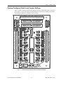
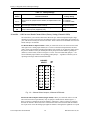
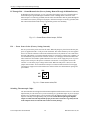
1
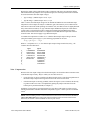
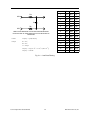
TS16 Temperature Sensor Board User’s Manual ® Real Time Devices USA, Inc. Accessing the Analog World™ TS16-9612 TS16 User’s Manual ® REAL TIME DEVICES USA, INC. Post Office Box 906 State College, Pennsylvania 16804 Phone: (814) 234-8087 FAX: (814) 234-5218 Published by Real Time Devices USA, Inc. P.O. Box 906 State College, PA 16804 Copyright © 1996 by Real Time Devices, Inc. All rights reserved Printed in U.S.A. 3/20/96 Table of Contents Introduction....................................................................................................................................... i-1 Multiplexing ................................................................................................................................................................ i-3 What Comes With Your Board .................................................................................................................................... i-3 Using This Manual ...................................................................................................................................................... i-4 When You Need Help .................................................................................................................................................. i-4 Chapter 1 Board Settings ................................................................................................................ 1-1 Factory-Configured Switch and Jumper Settings ....................................................................................................... 1-3 P3 and P4 — A/D Converter Board Channel Select (Factory Setting: Channel 1/GND) ................................... 1-4 P5 Through P20 — Ground Return Select (Factory Setting: Return Through 10 Kilohm Resistor) ................... 1-6 P21 — Power Source Select (Factory Setting: Internal) ........................................................................................ 1-6 Switching Thermocouple Chips ............................................................................................................................ 1-6 Chapter 2 Board Connections .......................................................................................................... 2-1 Connecting to the A/D Converter Board ..................................................................................................................... 2-3 Connecting to a 50-pin A/D Converter Board ...................................................................................................... 2-3 Connecting to a 40-pin A/D Converter Board ...................................................................................................... 2-3 Connecting to the Signal Sources ............................................................................................................................... 2-4 Connecting to Thermocouples ............................................................................................................................. 2-6 Chapter 3 Board Operation .............................................................................................................. 3-1 Signal Conditioning Circuitry ............................................................................................................................... 3-3 Multiplexing Circuitry ........................................................................................................................................... 3-3 Input Voltage Range ............................................................................................................................................. 3-3 Digital Control Lines ............................................................................................................................................. 3-3 Noise Compensation ............................................................................................................................................ 3-5 Appendix A TS16 Specifications ..................................................................................................... A-1 Appendix B Warranty ...................................................................................................................... B-1 Introduction Introduction TS16 Temperature Sensor Board i-1 Real Time Devices, Inc. TS16 Temperature Sensor Board i-2 Real Time Devices, Inc. Introduction The TS16 temperature sensor board provides amplification and cold junction compensation for J or K thermocouples. This external interface board features: • 16 thermocouple input channels, • J or K thermocouple compatibility, • Jumper-selectable connection of input return directly to ground for maximum noise immunity, • Circuit pads to install resistors and capacitors for input signal conditioning, • Miniature screw terminal blocks for easy input signal connection, • Extra I/O connector for daisy chaining, • Connector for external +12 volt power, • Complete compatibility with RTD’s 50-pin data acquisition boards. The following paragraphs briefly describe the major function of the board. A more detailed discussion of the board is included in Chapter 3, Board Operation. The board setup is described in Chapter 1, Board Settings. Multiplexing Two on-board multiplexers receive up to 16 thermocouple input channels and route them to the selected channel on the A/D converter board. The A/D converter channel to which the inputs are fed is selected using jumpers on the TS16. All programming is done through four digital control lines connected from the A/D converter board to the TS16. The voltage output of the TS16 channels should not exceed the input range of A/D converter board. Signal Conditioning The thermocouple output is conditioned by an on-board precision monolithic thermocouple amplifier with cold junction compensation. The AD594 is pretrimmed for type J thermocouples and the AD595 is pretrimmed for type K thermocouples. Both amplifier chips are included with your board and can be exchanged easily since the part is mounted in a socket. What Comes With Your Board You receive the following items in your TS16 package: • TS16 temperature sensor board with AD594 (J type) amplifier installed • AD595 (K type) amplifier IC • User’s manual If any item is missing or damaged, please call Real Time Devices’ Customer Service Department at (814) 234-8087. If you require service outside the U.S., contact your local distributor. In addition to the items included in your TS16 package, Real Time Devices offers a full line of board accessories. Key accessories for the TS16 include the XT50 twisted pair flat ribbon cable, TB50 terminal board and XB50 prototype/terminal board which can be connected to the daisy chain connector for prototype development and easy signal access, and the DWK-1 and DWK-2 discrete wire kits for connecting 40-pin A/D converter boards to the 50-pin TS16 board. TS16 Temperature Sensor Board i-3 Real Time Devices, Inc. Using This Manual Using This Manual This manual is intended to help you get your new board running quickly, while also providing enough detail about the board and its functions so that you can enjoy maximum use of its features even in the most complex applications. We assume that you already have an understanding of data acquisition principles and that you can provide the software necessary to control the TS16 board. When You Need Help This manual provides enough information to properly use your board’s features. If you have any problems installing or using this board, contact our Technical Support Department, (814) 234-8087, during regular business hours, eastern standard time or eastern daylight time, or send a FAX requesting assistance to (814) 234-5218. When sending a FAX request, please include your company’s name and address, your name, your telephone number, and a brief description of the problem. TS16 Temperature Sensor Board i-4 Real Time Devices, Inc. Chapter 1 Board Settings Chapter 1 Board Settings The TS16 board has jumper settings you can change if necessary for your application. The factory settings are listed and shown on a diagram in the beginning of this chapter. Should you need to change these settings, use these easy-to-follow instructions. TS16 Temperature Sensor Board 1-1 Real Time Devices, Inc. TS16 Temperature Sensor Board 1-2 Real Time Devices, Inc. Chapter 1 Board Settings Factory-Configured Switch and Jumper Settings Table 1-1 (on the next page) lists the factory settings of the user-configurable jumpers on the TS16 board. Figure 1-1 shows the board layout and the locations of the factory-set jumpers. The following paragraphs explain how to change the factory settings. Fig. 1-1 — Board Layout Showing Factory-Configured Settings TS16 Temperature Sensor Board 1-3 Real Time Devices, Inc. Factory-Configured Switch and Jumper Settings Table 1-1: Factory Settings Jumper/ Switch Function Controlled Factory Setting P3, P4 Select the channel that the TS16 is connected to on the A/D converter board. One or two jumpers must be installed, as explained later in this chapter. P3 = Channel 1; P4 = Channel 1 GND P5-P20 Connects the negative (iron or chromel) side of the thermocouple to ground through a 10 kilohm resistor or directly Connected to ground through 10 K resistor P21 Connects the TS16 power to the internal power (supplied from A/D board) or external power (supplied by user). Connected to internal power P3 and P4 — A/D Converter Board Channel Select (Factory Setting: Channel 1/GND) The TS16 allows you to monitor and collect data from up to 16 thermocouples through a single channel on your A/D converter board. P3 and P4 are used to select which analog input channel on your A/D converter board you connect to the TS16. These connectors accommodate A/D converter boards with up to 16 channels. For Boards With 1-8 Input Channels: When you connect the TS16 to an A/D converter board with eight or fewer analog input channels, P3 is used to set the desired input channel, and P4 is used to set the corresponding ground for that channel. For example, if you place the jumper across the pins for channel 1 on P3, you should place the P4 jumper across the channel 1 ground pins (labeled (1) on the board), as shown in Figure 1-2 below. You must install both jumpers — the selected channel jumper and the corresponding ground jumper — regardless of whether you are operating in the single-ended or differential mode. CHANNEL SELECT GND SEL 8 16 (8) 7 15 (7) 6 14 (6) 5 13 (5) 4 12 (4) 3 11 (3) 2 10 (2) 1 9 (1) P3 P4 Fig. 1-2 — Channel Select Jumpers, 8-Channel A/D Boards For Boards With 16 Input Channels (Single-Ended): When you connect the TS16 to an A/D converter board with 16 input channels, only one jumper is installed on P3 and P4. Figure 1-3 shows you how to configure the TS16 for channel 1, and Figure 1-4 shows you how to configure the TS16 for channel 9 when used with a 16-channel A/D converter board. Note that the leftmost row of pins on P3 carries the analog input signal for channels 1 through 8, the rightmost row of pins TS16 Temperature Sensor Board 1-4 Real Time Devices, Inc. Chapter 1 Board Settings on P3 provides the common signal for all 16 channels, and the leftmost row of pins on P4 carries the analog input signal for channels 9 through 16. The rightmost row of pins on P4 is connected to ground and is not used when connecting to a 16-channel A/D converter board. CHANNEL SELECT GND SEL 8 16 (8) 7 15 (7) 6 14 (6) 5 13 (5) 4 12 (4) 3 11 (3) 2 10 (2) 1 9 (1) P3 P4 Fig. 1-3 — Connecting Channel 1 to a 16-Channel A/D Board CHANNEL SELECT GND SEL 8 16 (8) 7 15 (7) 6 14 (6) 5 13 (5) 4 12 (4) 3 11 (3) 2 10 (2) 1 9 (1) P3 P4 Fig. 1-4 — Connecting Channel 9 to a 16-Channel A/D Board TS16 Temperature Sensor Board 1-5 Real Time Devices, Inc. Factory-Configured Switch and Jumper Settings P5 Through P20 — Ground Return Select (Factory Setting: Return Through 10 Kilohm Resistor) P5 through P20, shown in Figure 1-5, lets you connect the negative side (iron or chromel side) of the thermocouple to ground through a 10 kilohm resistor or through direct connection. If the thermocouple is not remotely grounded, then the connection should be made to ground through the 10 kilohm resistor (factory setting for all jumpers). If the thermocouple is remotely grounded, then this connection should be made directly to ground for greatest noise immunity. P5 GND Fig. 1-5 — Ground Return Select Jumper, P5-P20 P21 — Power Source Select (Factory Setting: Internal) P21 lets you select the power source for the TS16. When the jumper is placed across the INT pins, power is supplied from the +5 volt pin on the A/D board. This will be satifactory for most applications. If several TS16 boards or other front-end boards such as relay boards are to be connected to the same A/D board or if you suspect that the internal +5 volt supply is causing noisy readings, it is reccomended that you power the TS16 from an external +12 volt supply connected to TB4 or J35. These connectors are hooked in parallel and either one can be used to supply the power. If you are using J35, the center pin is the positive connection. An internal +5 volt regulator converts the external +12 volts to the proper voltage for the board. When external power is used, move the jumper on P21 to EXT. J35 is a standard 2.0 mm power connector. Real Time Devices can supply external power supplies to be used with the TS16. Please call for more information on pricing and part numbers. P21 INT EXT Fig. 1-6 — Power source select, P21 Switching Thermocouple Chips: The TS16 board has been shipped with the AD594 amplifier installed in the socket at U3. This is the amplifier that you will want to use if you are measuring "J" type thermocouples. If you are trying to measure "K" type thermocouples, you will need to replace the AD594 amplifier with the AD595 amplifier. This chip was shipped along with your board. NOTE: When replacing the amplifier chip, be careful to insert the chip with the proper pin 1 location. Also be sure to ground yourself to the computer chasis to reduce the risk of static electricity damage. TS16 Temperature Sensor Board 1-6 Real Time Devices, Inc. Chapter 2 Board Connections Chapter 2 Board Connections This chapter tells you step-by-step how to connect the TS16 board to your A/D converter board and to your external signal sources. TS16 Temperature Sensor Board 2-1 Real Time Devices, Inc. TS16 Temperature Sensor Board 2-2 Real Time Devices, Inc. Chapter 2 Board Connections Connecting to the A/D Converter Board Connecting to a 50-pin A/D Converter Board Figure 2-1 shows the TS16’s P1 I/O connector pinout, with all of the pins used by the TS16 board labeled. The TS16 is pin-for-pin compatible with all Real Time Devices’ 50-pin I/O connector boards. For these boards, all of the unlabeled pins on the TS16 carry the same signal found at the I/ O connector of the A/D converter board you are using. If you want to access other signals on your A/D converter board, such as digital I/O or timer/ counters, you can connect to the 16 signals available on TB3 at the top of the TS16 board, shown in Figure 2-2. This terminal strip is labeled with the pin numbers brought out to it from the 50-pin connector. To find the signals available on these pins, refer to the A/D converter board’s pinout included in the board’s manual. To further expand your thermocouple monitoring capability by adding more TS16 boards, you can use the daisy chain connector on the TS16 board, P2. The signals at this connector are identical to the pinout of your 50-pin A/D converter board. You can connect to another TS16 board, or to a TB50 or XB50 breakout board to easily access all of the digital I/O and timer/counter signals. Our technical staff will gladly help you select the accessories you need for your application. WARNING! If you connect more than one TS16 board to an A/D converter board, be sure that you select a different A/D converter board channel for each TS16 board used (header connectors P3 and P4 on the TS16). If you try to connect more than one TS16 to the same channel, damage to the boards and data acquisition system can result! Connecting to a 40-pin A/D Converter Board The TS16 can be adapted for use with all Real Time Devices’ 40-pin A/D converter boards by making I/O connections using an RTD Discrete Wire Kit. Available with single or twisted pair wiring, this kit is designed so that you can mate connectors with otherwise incompatible pinouts. Using Figure 2-1 and the pinout diagram for your A/D converter board, you can make the appropriate connections. TS16 Temperature Sensor Board 2-3 Real Time Devices, Inc. Connecting to the Signal Sources CHANNEL 1 1 2 CHANNEL 9/(GND 1) CHANNEL 2 3 4 CHANNEL 10/(GND 2) CHANNEL 3 5 6 CHANNEL 11/(GND 3) CHANNEL 4 7 8 CHANNEL 12/(GND 4) CHANNEL 5 9 10 CHANNEL 13/(GND 5) CHANNEL 6 11 12 CHANNEL 14/(GND 6) CHANNEL 7 13 14 CHANNEL 15/(GND 7) CHANNEL 8 15 16 CHANNEL 16/(GND 8) 17 18 19 20 ANALOG GND 21 22 ANALOG GND 23 24 25 26 27 28 29 30 31 32 DIN 3 33 34 DIN 2 35 36 DIN 1 37 38 DIN 0 39 40 41 42 43 44 45 46 +12 VOLTS 47 48 +5 VOLTS -12 VOLTS 49 50 DIGITAL GND Fig. 2-1 — P1 I/O Connector Pin Assignments Connecting to the Signal Sources Figure 2-2 shows TB1 and TB2, where the thermocouple output signals are connected. These 20terminal miniature screw terminal strips let you easily connect and disconnect analog inputs to the board. Four additional analog ground terminals are provided on each strip for your convenience when connecting signal sources. TS16 Temperature Sensor Board 2-4 Real Time Devices, Inc. Chapter 2 Board Connections Fig. 2-2 — TS16 Board Layout TS16 Temperature Sensor Board 2-5 Real Time Devices, Inc. Connecting to the Signal Sources Connecting to Thermocouples Up to 16 thermocouples (all J or all K type) can be connected to the TS16. If the thermocouple is not remotely grounded, then the ground connection on the TS16 should be made through the 10 kilohm resistor installed on the board. This is the factory setting for all 16 inputs (using P5-P20). This connection assures that common mode voltages induced in the thermocouple loop are not converted to normal mode voltages. If a remote ground is provided at the thermocouple, then the input can be connected directly to ground by changing the setting ofthe corresponding ground return jumper, as described in Chapter 1. Direct connection to ground provides the greatest noise immunity. Figure 2-3 shows you how to make the thermocouple connections. TS16 TERMINAL BLOCKS, TB1 & TB2 IN 1+ THERMOCOUPLE 1 IN 1- P5 10 K P20 10 K IN 16+ THERMOCOUPLE 16 IN 16- Fig. 2-3 — Thermocouple Connections TS16 Temperature Sensor Board 2-6 Real Time Devices, Inc. Chapter 3 Board Operation Chapter 3 Board Operation This chapter describes the features of the TS16 and board operation. On-board pads allow the addition of low-pass filtering, as described near the end of the chapter. TS16 Temperature Sensor Board 3-1 Real Time Devices, Inc. TS16 Temperature Sensor Board 3-2 Real Time Devices, Inc. Chapter 3 Board Operation The TS16 provides amplification and cold junction compensation for up to 16 J or K type thermocouples and routes them into a single input channel on your A/D converter board. Multiplexing Circuitry The TS16 uses two 16-input analog multiplexers to provide a single output which is fed to the selected input channel on an A/D converter board. Each multiplexer has ±35 Vdc overvoltage protection to protect it against accidental signal overloads. Input Voltage Range The input voltage range of the TS16 is determined by the range of the A/D converter board. For example, if the A/D board is set for a ±5 volt range, then the TS16 board’s output should be within the range of ±5 volts. The A/D board’s input voltage range should be selected so that it will accommodate the amplified output range of the thermocouples you are monitoring. Digital Control Lines Four digital control lines, DIN0 through DIN3 (or DOUT0 through DOUT3 when looking at the signals output from the A/D converter board), let you select which TS16 channel is active. These lines are programmed from your A/D converter board where they must be configured as digital output lines. The TS16 cannot be controlled by analog lines! If your board’s digital I/O is provided by an 8255 programmable peripheral interface (PPI), then you must set up the lines that you use for TS16 channel selection as mode 0 outputs. The A/D converter board manual tells you how to set up the PPI. Table 3-1 shows the 4-bit digital words and their corresponding channel selections. Table 3-1: Analog Input Channel Select, DIN0-DIN3 Input Channel DIN Line Setting 3 2 1 0 Input Channel DIN Line Setting 3 2 1 0 1 0 0 0 0 9 1 0 0 0 2 0 0 0 1 10 1 0 0 1 3 0 0 1 0 11 1 0 1 0 4 0 0 1 1 12 1 0 1 1 5 0 1 0 0 13 1 1 0 0 6 0 1 0 1 14 1 1 0 1 7 0 1 1 0 15 1 1 1 0 8 0 1 1 1 16 1 1 1 1 Signal Conditioning Circuitry The heart of the temperature sensing circuitry is the AD594 (J type) or AD595 (K type) instrumentation amplifier and cold junction compensator. This precision chip combines an ice point reference with a precalibrated amplifier to provide a high level output of 10 mV/°C directly from the thermocouple signal. TS16 Temperature Sensor Board 3-3 Real Time Devices, Inc. Table 3-2: Output Voltage vs. Thermocouple Temperature (Ambient +25¡C, Vs = +12V, -12V) Thermocoupl Type J Temp. Voltage (¡C) (mV) AD594 Output (mV) Type K Voltage (mV) AD595 Output (mV) Thermocoupl Type J Temp. Voltage (¡C) (mV) AD594 Output (mV) Type K Voltage (mV) AD595 Output (mV) -200 -7.890 -1523 -5.891 -1454 500 27.388 5300 20.640 5107 -180 -7.402 -1428 -5.550 -1370 520 28.511 5517 21.493 5318 -160 -6.821 -1316 -5.141 -1269 540 29.642 5736 22.346 5529 -140 -6.159 -1188 -4.669 -1152 560 30.782 5956 23.198 5740 -120 -5.426 -1046 -4.138 -1021 580 31.933 6179 24.050 5950 -100 -4.632 -893 -3.553 -876 600 33.096 6404 24.902 6161 -80 -3.785 -729 -2.920 -719 620 34.273 6632 25.751 6371 -60 -2.892 -556 -2.243 -552 640 35.464 6862 26.599 6581 -40 -1.960 -376 -1.527 -375 660 36.671 7095 27.445 6790 -20 -.995 -189 -.777 -189 680 37.893 7332 28.288 6998 -10 -.501 -94 -.392 -94 700 39.130 7571 29.128 7206 0 0 3.1 0 2.7 720 40.382 7813 29.965 7413 10 .507 101 .397 101 740 41.647 8058 30.799 7619 20 1.019 200 .798 200 750 42.283 8181 31.214 7722 25 1.277 250 1.000 250 760 - - 31.629 7825 30 1.536 300 1.203 300 780 - - 32.455 8029 40 2.058 401 1.611 401 800 - - 33.277 8232 50 2.585 503 2.022 503 820 - - 34.095 8434 60 3.115 606 2.436 605 840 - - 34.909 8636 80 4.186 813 3.266 810 860 - - 35.718 8836 100 5.268 1022 4.095 1015 880 - - 36.524 9035 120 6.359 1233 4.919 1219 900 - - 37.325 9233 140 7.457 1445 5.733 1420 920 - - 38.122 9430 160 8.560 1659 6.539 1620 940 - - 38.915 9626 180 9.667 1873 7.338 1817 960 - - 39.703 9821 200 10.777 2087 8.137 2015 980 - - 40.488 10015 220 11.887 2302 8.938 2213 1000 - - 41.269 10209 240 12.998 2517 9.745 2413 1020 - - 42.045 10400 260 14.108 2732 10.560 2614 1040 - - 42.817 10591 280 15.217 2946 11.381 2817 1060 - - 43.585 10781 300 16.325 3160 12.207 3022 1080 - - 44.349 10970 320 17.432 3374 13.039 3327 1100 - - 45.108 11158 340 18.537 3588 13.874 3434 1120 - - 45.863 11345 360 19.640 3801 14.712 3641 1140 - - 46.612 11530 380 20.743 4015 15.552 3849 1160 - - 47.356 11714 400 21.846 4228 16.395 4057 1180 - - 48.095 11897 420 22.949 4441 17.241 4266 440 24.054 4655 18.088 4476 460 25.161 4869 18.938 4686 480 26.272 5084 19.788 4896 TS16 Temperature Sensor Board 3-4 Real Time Devices, Inc. Chapter 3 Board Operation Because the output voltage of the thermocouple is nonlinear with respect to temperature and the AD594/AD595 linearly amplifies the compensated signal, the following transfer functions should be used to determine the actual output voltages: • Type J voltage = (AD594 output / 193.4) - 16 µV • Type K voltage = (AD595 output / 247.3) - 11 µV Table 3-2 shows the ideal output voltages for the AD594 and AD595 for selected thermocouple temperatures. These outputs are subject to calibration, gain, and sensitivity errors which must be taken into account in the actual operating environment. Also, note that, because of slightly different alloy content between ANSI (U.S.) type J thermocouples and DIN (European) Fe-CuNi thermocouples, Table 3-2 should not be used in conjunction with European standard thermocouples. Instead, use the transfer function above in conjunction with a DIN thermocouple table to obtain accurate results. This does not apply to type K thermocouples. To estimate the temperature to within ±0.7°C when the thermocouple output voltage is known (using the formulas given on page 3-3), the following polynomial can be used: T = a0 + a1V + a2V2 + ... + anVn Where T = temperature in °C, V = the thermocouple output voltage in millivolts, and an = the constants from the table below: Type J a0 a1 a2 a3 a4 a5 a6 a7 a8 -0.048868252 19873.14503 -218614.5353 11569199.78 -264917531.4 2018441314 Type K 0.226584602 24152.10900 67233.42488 2210340.682 -860963914.9 4.83506x10¹⁰ -1.18452x10¹² 1.38690x10¹³ -6.33708x10¹³ Noise Compensation Because of the low output voltages from the thermocouples, care should be taken to minimize noise in the thermocouple circuitry. Ways in which you can reduce noise are: • Locate the TS16 as close as possible to the thermocouple sources. This allows amplification of the thermocouple output before long transmission to the A/D converter board. • If the thermocouple is remotely grounded, connect the negative (iron or chromel) side directly to ground on the TS16. This is accomplished by placing the jumper on P5-P20 across the bottom pair of pins labeled GND (see Chapter 1). In addition, circuit pads are provided to install a low-pass filter on the inputs to reduce noise by filtering out harmonics and other undesirable components. Figure 3-1 shows you how to build this circuit. NOTE: When installing resistors on the board in the locations referenced in the table, be sure to remove the solder blob on the bottom side of the board between the two leads of each resistor. Otherwise, the resistor is shorted and has no effect in your circuit! TS16 Temperature Sensor Board 3-5 Real Time Devices, Inc. Ra AIN + Ca Rb AIN REMOVE SOLDER SHORT ON BOTTOM OF BOARD BETWEEN LEAD PADS FOR Ra AND Rb WHEN INSTALLING RESISTORS ON THE BOARD! Formula: Frequency = 1/[2π(Ra+Rb)Ca] Example: Ra = 10 kΩ Rb = 10 kΩ Ca = 1000 pF 3 3 -12 Frequency = 1/2π[(10 x 10 + 10 x 10 ) x (1000 x 10 )] Frequency = 7.958 kHz Channel Ra Rb Ca 1 R1 R17 C1 2 R2 R18 C2 3 R3 R19 C3 4 R4 R20 C4 5 R5 R21 C5 6 R6 R22 C6 7 R7 R23 C7 8 R8 R24 C8 9 R9 R25 C9 10 R10 R26 C10 11 R11 R27 C11 12 R12 R28 C12 13 R13 R29 C13 14 R14 R30 C14 15 R15 R31 C15 16 R16 R32 C16 Fig. 3-1 — Low-Pass Filtering TS16 Temperature Sensor Board 3-6 Real Time Devices, Inc. Appendix A TS16 Specifications Appendix A TS16 TS16 Temperature Sensor Board A-1 Specifications Real Time Devices, Inc. TS16 Temperature Sensor Board A-2 Real Time Devices, Inc. Appendix A TS16 Specifications TS16 Characteristics Typical @ 25° C Input Circuitry Number of channels ....................................................................................................... 16 Maximum input voltage ........................................................................................ ±12 Vdc Overvoltage protection ......................................................................................... ±35 Vdc ThermocoupleAmplifier ..................................................................... AD594/AD595 Thermocouple type ..................................................................... J (AD594) or K (AD595) Closed loop gain ............................................................. 193.4 (AD594) or 247.3 (AD595) Output range ....................................................................................................... ±10 Vdc Output scaling ................................................................................................... 10 mV/°C Temperaturemeasurementrange ............................................................... -200 to +1000°C Calibration error ........................................................................................................ ±3°C Ambient temperature range ............................................................................... 0 to +50°C PowerRequirements +5 volts (Internal Power) ....................................................................................... +80 mA +12 volts (External Power) .................................................................................... +40 mA Connectors Two 50-pin shrouded headers with ejector tabs ScrewTerminals TB1 and TB2 - 20-terminal; TB3 - 16-terminal; TB4 - 3-terminal 22-12 AWG wire Size 6.875"L x 5.0"W (175mm x 127mm) TS16 Temperature Sensor Board A-3 Real Time Devices, Inc. TS16 Temperature Sensor Board A-4 Real Time Devices, Inc. Appendix B Warranty TS16 Temperature Sensor Board B-1 Real Time Devices, Inc. TS16 Temperature Sensor Board B-2 Real Time Devices, Inc. LIMITED WARRANTY Real Time Devices, Inc. warrants the hardware and software products it manufactures and produces to be free from defects in materials and workmanship for one year following the date of shipment from REAL TIME DEVICES. This warranty is limited to the original purchaser of product and is not transferable. During the one year warranty period, REAL TIME DEVICES will repair or replace, at its option, any defective products or parts at no additional charge, provided that the product is returned, shipping prepaid, to REAL TIME DEVICES. All replaced parts and products become the property of REAL TIME DEVICES. Before returning any product for repair, customers are required to contact the factory for an RMA number. THIS LIMITED WARRANTY DOES NOT EXTEND TO ANY PRODUCTS WHICH HAVE BEEN DAMAGED AS A RESULT OF ACCIDENT, MISUSE, ABUSE (such as: use of incorrect input voltages, improper or insufficient ventilation, failure to follow the operating instructions that are provided by REAL TIME DEVICES, “acts of God” or other contingencies beyond the control of REAL TIME DEVICES), OR AS A RESULT OF SERVICE OR MODIFICATION BY ANYONE OTHER THAN REAL TIME DEVICES. EXCEPT AS EXPRESSLY SET FORTH ABOVE, NO OTHER WARRANTIES ARE EXPRESSED OR IMPLIED, INCLUDING, BUT NOT LIMITED TO, ANY IMPLIED WARRANTIES OF MERCHANTABILITY AND FITNESS FOR A PARTICULAR PURPOSE, AND REAL TIME DEVICES EXPRESSLY DISCLAIMS ALL WARRANTIES NOT STATED HEREIN. ALL IMPLIED WARRANTIES, INCLUDING IMPLIED WARRANTIES FOR MECHANTABILITY AND FITNESS FOR A PARTICULAR PURPOSE, ARE LIMITED TO THE DURATION OF THIS WARRANTY. IN THE EVENT THE PRODUCT IS NOT FREE FROM DEFECTS AS WARRANTED ABOVE, THE PURCHASER’S SOLE REMEDY SHALL BE REPAIR OR REPLACEMENT AS PROVIDED ABOVE. UNDER NO CIRCUMSTANCES WILL REAL TIME DEVICES BE LIABLE TO THE PURCHASER OR ANY USER FOR ANY DAMAGES, INCLUDING ANY INCIDENTAL OR CONSEQUENTIAL DAMAGES, EXPENSES, LOST PROFITS, LOST SAVINGS, OR OTHER DAMAGES ARISING OUT OF THE USE OR INABILITY TO USE THE PRODUCT. SOME STATES DO NOT ALLOW THE EXCLUSION OR LIMITATION OF INCIDENTAL OR CONSEQUENTIAL DAMAGES FOR CONSUMER PRODUCTS, AND SOME STATES DO NOT ALLOW LIMITATIONS ON HOW LONG AN IMPLIED WARRANTY LASTS, SO THE ABOVE LIMITATIONS OR EXCLUSIONS MAY NOT APPLY TO YOU. THIS WARRANTY GIVES YOU SPECIFIC LEGAL RIGHTS, AND YOU MAY ALSO HAVE OTHER RIGHTS WHICH VARY FROM STATE TO STATE. TS16 Temperature Sensor Board B-3 Real Time Devices, Inc. TS16 Temperature Sensor Board B-4 Real Time Devices, Inc.