1
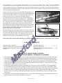
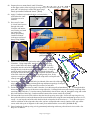
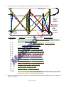
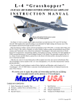
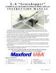
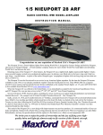
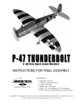
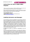
CURTISS JN-4 “JENNY”
INSTRUCTION MANUAL
Shown with optional gasoline engine, propeller and spinner.
Specifications:*
Wingspan ............................................................................. Upper wing – 1 0 5 inches
(This is 20% of the original Jenny’s 43 feet 7¾ inch wingspan)
Wing Area ..................................................................................... 1 , 7 6 0 square inches
Length .............................................................................................................. 7 8 inches
Flying weight ................................................................................................ 2 0 pounds
Engine (Not included) .................... 40CC to 50CC Gas or 1.6 cu. inch to 1.8 cu. inch Glow
(Recommended: Maxford USA’s CRRC GF50i or equivalent)
Propeller (Not included) .......................................................................................... 2 2× 8
Radio system (Not included) .................. Minimum of 4 channels with 5 standard servos
(Recommended servos: Maxford USA SG5010 or equivalent)
*(Dimensions and weights are approximate.)
Entire Contents © Copyright 2009
Congratulations on your acquisition of Maxford USA’s version of the Curtiss JN-4 “Jenny” from World War I.
The Curtiss JN-4 "Jenny" two-seat biplane was one of the most popular airplanes of all time. It was the first mass-produced
airplane and was manufactured in larger numbers than any previous American airplane. By the time of the Armistice in 1918,
well over 6,000 JN-4s had been built.
Jennys were used to train 95% of all World War I United States and
Canadian pilots; flying schools in Australia, the United Kingdom and
France also used them. Sadly, as a consequence, nearly 20% of all
Jennys ever built were lost in the course of flight instruction.
For a brief time after the war, the U.S. Postal Service used a few
Jennys for airmail service between Washington, D.C., Philadelphia,
and New York. Ultimately, the thousands of surplus JN-4s in the U.S.
were sold to private owners at bargain prices. Charles Lindbergh’s
first airplane was a surplus Jenny – purchased in 1923 for $500.
Many of these new owners used their Jennys to earn a living as stunt
pilots. Flying from unprepared fields on the outskirts of towns, they
thrilled audiences with daring exhibitions of wing-walking, aerial
trapeze work, and low-level aerobatics.
The barnstorming era helped awaken America to aviation. However,
this post-war glut of low-cost aircraft effectively killed the market for
new aircraft until the mid-1920s, as the supply of surplus aircraft
finally became exhausted. Today, only about 50 Jennys survive in
museums or in the hands of a few fortunate private owners.
Enjoy the pride of ownership and the joy of flying your high-quality model of the famous JN-4 Jenny!
TABLE OF CONTENTS
Important safety precautions ...................................... 2
Warranty, liability waiver, and return policy ............. 3
Special features of this JN-4 “Jenny” model .............. 4
Parts list ...................................................................... 4
Assembly instructions ........................................... 5
Setup and Adjustments ....................................... 17
Preparation for Transport and Field Setup .......... 17
Pre-Flight Checks ............................................... 17
IMPORTANT SAFETY PRECAUTIONS
TO PROTECT YOUR MODEL, YOURSELF & OTHERS
1. This product should not be considered a toy, but rather a sophisticated, working model that functions much like a fullscale airplane. Because of its performance capabilities, this product, if not assembled and operated correctly, could
cause injury to you or spectators and damage to property. Maxford USA provides you with a high-quality, thoroughly
tested model airplane kit with assembly instructions. However, the quality and capabilities of your finished model
airplane depends on how you build it, and your safety depends on how you use and fly it. Any testing or flying of this
model airplane is done entirely at your own risk.
2. Assemble the model airplane according to the instructions. Take time to build it STRAIGHT, TRUE and STRONG.
We recommend that you do not alter or modify the model, as doing so may result in an unsafe or unworkable model.
In a few cases the instructions may differ slightly from the photos. In those instances the written instructions should be
considered as correct. If you have any question about the instructions, before you proceed with assembly of this
product, contact us at (562) 529-3988, Monday through Friday, except national holidays, between 8:30 AM to 5 PM
Pacific time.
3. Install the R/C system and other components in such a way that this model airplane passes all ground safety/range tests
[Continued.]
and ensure that all controls operate smoothly and correctly.
Page 2 of 18 pages
4. Check the operation of this model airplane before every flight to ensure that all equipment is still operating correctly
and that the model has remained structurally sound. Also, before every flight check the clevises and other connectors;
replace any found damaged or defective.
5. If you are not an experienced R/C pilot or have not flown this type of model before, we recommend that you get the
assistance of an experienced R/C pilot.
6. Throughout the lifetime of this model use only the recommended Maxford USA or same-sized engine and a wellmaintained R/C radio system.
7. While this kit has been flight-tested to meet or exceed our rigid performance and reliability standards in normal use, if
you plan to perform any extremely high-stress flying, such as racing or advanced aerobatics, or if you plan to install a
larger engine than recommended, you (the buyer or user of this product) are solely responsible for taking steps to
reinforce the high-stress points and/or substitute hardware that is more suitable for such increased stresses.
8. LITHIUM BATTERY HANDLING & USAGE: WARNING!! If you elect to use a lithium battery in this model
airplane, read the entire instruction sheet included with the battery. Failure to follow all instructions could result in
permanent damage to the battery, its surroundings, and bodily harm! If you crash this model airplane, check whether
the Li-Po battery is damaged.
Do NOT attempt to use and do not attempt to re-charge a damaged Li-Po battery.
ONLY use a Li-Po approved charger.
NEVER charge in excess of 4.2V per cell.
(NEVER use a NiCd/NiMH charger!)
NEVER discharge below 2.5V per cell.
ALWAYS set the charger’s output to match the battery’s
NEVER allow battery temp. to exceed 150° F (65° C).
voltage and mAh ratings.
NEVER charge at currents greater than 1C (for example,
ALWAYS charge through the battery’s “charge” connector.
in the case of a 1,300 mAh battery, that’s 1.3 amps).
(NEVER charge through the “discharge” leads.)
NEVER trickle charge.
ALWAYS charge in a fireproof location.
NEVER disassemble or modify pack wiring in any way
NEVER place on combustible materials or leave unattended
or puncture cells.
during charge or discharge.
ALWAYS KEEP OUT OF REACH OF CHILDREN.
9. This model of the Curtis JN-4 “Jenny” includes carbon-fiber reinforced and fiberglass parts. Be warned that carbonfiber and fiberglass dust may cause eye, skin and respiratory-tract irritation. So, whenever you grind, drill or sand such
parts, always wear safety goggles, a particle mask and rubber gloves, and never blow into such parts to remove carbonfiber or fiberglass dust, as the dust may blow back into your eyes.
WARRANTY, LIABILITY WAIVER, AND RETURN POLICY
Maxford USA guarantees this kit to be free from defects in material and workmanship at the time of purchase. All of our
products have been inspected in our factory and are checked again when shipped from our warehouse. However, Maxford
USA cannot directly control any of the materials you may use nor your final-assembly process. Therefore, Maxford USA
CANNOT in any way guarantee the performance of your finished model airplane. Furthermore, in purchasing this product,
you (the buyer or user of this product) exempt, waive, and relieve Maxford USA from all current or future liability for any
personal injury, property damage, or wrongful death, and if you (the buyer or user of this product) are involved in any claim or
suit, you will not sue Maxford USA or any of its representatives.
If you do not fully accept the above liability and waiver, you may request a return merchandise authorization number (RMA#)
as explained in item 2, below.
If you think there is any shipping damage or missing part(s), please review our after-sales service and return policy as outlined
below.
1. Inspect your order upon delivery for any shipping damage or missing part. If you find a problem you must contact us
within 10 days from receipt of your purchase by calling (562) 529-3988, Monday through Friday, except holidays,
between the hours of 8:30 AM and 5 PM Pacific time. During this telephone conversation, and with your support, we
will determine how to resolve your concern. (Note: Maxford USA Li-Po batteries are sold without warranty and are
not eligible for return or credit.)
2. To request an RMA#, call (562) 529-3988, Monday through Friday, except holidays, between the hours of 8:30 AM to
5 PM Pacific time. If we elect to issue you an RMA#, you must clearly mark this RMA# on the outside of the package.
(No return or exchange will be authorized after 10 days from the date of your receipt of the product; any package
delivered to us without a Maxford USA RMA# is subject to being returned to the sender, as received, with return
Page 3 of 18 pages
postage payable upon delivery.) Returned merchandise must be in its original condition as received from Maxford
USA, with no assembly or modification, in the original packing materials, complete with all manuals and accessories.
Return shipping and insurance charges must be prepaid by you, the buyer.
3. Returned merchandise that is accepted by Maxford USA for credit is subject to a 10% to 20% restocking fee. The final
amount will be determined by Maxford USA upon receipt and examination of the returned merchandise.
Return Address:
Maxford USA RC Model Mfg, Inc.
15247 Texaco Avenue
Paramount, CA 90723-3917
(IMPORTANT: If issued by Maxford USA, print
the RMA# on the package near the above address.)
SPECIAL FEATURES OF THIS CURTISS JN-4 “JENNY” MODEL
•
•
•
•
•
•
•
Fiberglass cowl with scale dummy 90 HP Curtiss OX-5 V8 engine and radiator.
All airframe assemblies are precovered & pretrimmed.
Aileron hinge-slots are precut, and each aileron is separately operated by its own in-wing servo.
All required openings are predrilled and/or precut.
Cockpit and windshield coaming is preinstalled.
Pull-pull cables and clevises for elevator and rudder control are preinstalled.
Landing gear is preformed, and wheels, wheel collars and a steerable tail wheel are included.
PARTS LIST
1. Items you must supply to complete the Curtiss JN-4:
• 5-minute epoxy or aliphatic resin glue, Cyanoacrylate (CA) adhesive, petroleum jelly, and a few common hand
tools (such as long-nosed and diagonal or side-cutter pliers, etc.).
• Engine (with ignition-kill system if gasoline powered), propeller and optional spinner.
• Five(5) SG-5010 or equivalent standard servos, one(1) 12-inch servo Y-connector,
three(3) 18-inch extensions, and a 4-channel radio transmitter and receiver.
2. Items included (all securely protected in two large carton-boxes):
• Precovered and pretrimmed fuselage with preinstalled elevator and
rudder pull-pull cables.
• Fiberglass cowl with scale dummy engine and radiator.
• Vertical and horizontal stabilizers, rudder and elevators with predrilled hinge holes.
• Precovered upper and lower-wing panels
with upper-wing’s center section.
• Wing joiners, preformed cabanes, struts,
control horns, hinges, flying wires and
related hardware, including self-threading
and machine screws, self-locking nuts
(except those normally supplied with the
servos and engine) and Allen wrenches.
• Preformed landing gear.
• Preassembled 500 mL fuel tank,
complete with tygon fuel tubing.
• CD-ROM with computer video and this
illustrated instruction manual.
Page 4 of 18 pages
ASSEMBLY INSTRUCTIONS
NOTE: Numbers within brackets are the starting points for viewing the CD-ROM’s computer-video in [Minutes:Seconds].
1. Unlatch, lift out and set aside the two(2) radio-compartment hatch covers. Remove and discard the wire ties at the
bottom of the fuselage, then pull out from the fuselage and set aside the wooden engine-mounting box and the
cardbaord box containing the cabanes and struts.
2. With the elevator servo’s output shaft toward the rear of the fuselage, install the elevator
servo in the servo tray’s rear-most position [00:06]. With the rudder servo’s output shaft
toward the rear of the fuselage, install the rudder servo in the servo tray’s second-from-thefront position [00:17].
3. Attach the two(2) preinstalled clevises with double wires
exiting the fuselage’s sides to the rear/elevator servo [00:41].
Attach the preinstalled clevises with single wires exiting the
fuselage’s top to the front/rudder servo [01:57].
4. Apply a dab of petroleum jelly to the center of the
eight(8) hinge points to protect them from glue. Using the
predrilled holes in the rudder and in each elevator, attach the
hinge points to the rudder and elevators with epoxy glue or
aliphatic resin [02:32]. Mount (and carefully center) controlhorn assemblies in the predrilled holes in each half of the
elevator and in the rudder [03:01].
5. Glue the rudder’s hinges into the two predrilled holes in the vertical
stabilizer using epoxy glue or aliphatic resin. Glue the elevator’s hinges
into the six predrilled holes in the horizontal stabilizer using epoxy
glue or aliphatic resin [04:05].
6. Position the horizontal stabilizer’s flat surface on its mounting platform at
the rear of the fuselage, insert three(3) of the 63 mm (2½-inch) hex-head
bolts into the holes in the horizontal stabilizer, and
secure (but
don’t overtighten) with the supplied hex wrench [04:25].
7. Insert the tabs at the base of the vertical stabilizer into the
slot in the horzintal stabilizer [04:45]. Insert two(2)
38 mm (1½-inch) hex-head bolts into the holes on the left
side of the fuselage, and secure (but don’t overtighten)
with the supplied hex wrench [05:00].
8. Attach the two(2) pull-pull wires exiting the top of the fuselage to the left and right control horns on the rudder.
Attach the pairs of pull-pull wires exiting the sides of the fuselage to the top and bottom control horns on each
half of the elevator [05:30].
Page 5 of 18 pages
9. Sight along the vertical stabilizer to the rudder and from the horizontal stabilizer to both elevators and make any
necessary adjustments to the length and tension of each pull-pull cable to center the control surfaces and to ensure
the rudder and both halves of the elevator are all at their ‘neutral’ position with their servos centered [06:22].
Once the pull-pull cables are adjusted, secure both ends of each cable by snugging the lock
nut on each brass pull-rod against its clevis, then permanently anchor each brass pull-rod
in its clevis with a few drops CA.
10. Drill a 1/16-inch hole in each elevator and the rudder control horn, centered between the existing hole for the pullpull cables’ clevise and the threaded metal rod.
11. Locate the two small predrilled holes at the trailing edge of each elevator. Run a sharp pin through each predrilled
hole to fully open the covering material at both sides of each hole.
12. Identify and unwrap the coil of wire containing 3 ea. 120 cm (47inch) lengthes of wire. (Careful: Don’t kink the wires!)
13. From the bottom side of either elevator, insert the end of one of
the 120 cm (47-inch) wire into the predrilled hole in the bottom of
the elevator that is nearest to the rudder. (Photos show the rightside’s elevator.) Pull approx. 90 cm (35 inches) of this wire
through the hole to the top side of the elevator (i.e., Leave approx. 30 cm [12 inches]
of wire at the bottom of the elevator). Insert the end of the wire which now prodrudes
from the top of the elevator into the hole in the elevator’s top control horn from the
side furthest from the rudder (i.e., Point end of the wire toward the rudder). Pull the
wire through the control horn’s hole and around the control horn, then insert the wire’s
end into the predrilled hole that is furthest from the rudder [06:41].
14. Bring the two ends of the wire together at the bottom of the elevator and slide a crimp
tube onto these two ends. Insert the wire’s ends into opposite sides of the hole in the
elevator’s bottom control horn. Use pliers to tighten the wire evenly across both
sides of the elevator; then use pliers to securely clamp the wires’ ends within the
crimp tube [07:12]. Trim/cut off and discard the excess wire ends.
Wire’s ends (color added for clarity)
inserted from the opposite sides of
the hole in the bottom control horn.
Wire’s ends fed back through the
crimp tube, with long-nosed pliers
pulling on the wire’s ends.
Completed installation of all wires
at the control horn on the bottom
of the right-side’s elevator.
15. Install a second 120 cm (47-inch) wing wire on the other half of the elevator by repeating steps 13 and 14.
16. Starting from the left side of the rudder, insert approx. 90cm (35 inches) of the remaining 120 cm (47-inch) wire
through the small opening near the top of the rudder [i.e., Leave approx. 30 cm (12 inches) of wire at the left side of
the rudder]. Insert the wire’s end which now projects from the rudder’s right side into the bottom side of the hole in
the rudder’s right control horn (i.e., Point the wire’s end upwards).
Page 6 of 18 pages
17. Pull the wire up through the control horn’s hole and bring it around the control horn; then insert the end of this wire
into the predrilled hole at the bottom of the right side of the rudder [09:04].
18. Bring together the wire’s two ends at the left side of the rudder, and slide a crimp tube onto these two loose ends.
Insert the wire’s ends into opposite sides of the hole in the rudder’s left control horn. Use pliers to pull the wire’s
ends to tighten the wire evenly across both sides of the rudder; then use pliers to securely clamp the wires’ ends
within the crimp tube [09:30]. Trim/cut off and discard the excess wire ends.
19. Using the two predrilled holes and preinstalled T-nuts in the
bottom rear of the fuselage,
attach the tail wheel’s
spring-mount to the fuselage
using the two(2)
supplied 1.5 cm (5/8-inch) bolts.
Secure each bolt into its T-nut with Loctite
Screw Lock or equivalent [10:37].
20. Attach a metal T-bracket to the bottom of the rudder
with the supplied three(3)
7 mm (¼-inch) wood
screws. Secure each screw with
Loctite Screw
Lock or equivalent compound.
Position a coil spring on each side of and
between the T-bracket and the tail-wheel’s
steering arm. Adjust each spring’s length to align
the tail wheel with the rudder (and to provide shock
relief to the rudder servo); secure both ends of each spring
by winding the spring’s wire ends around the steering arm
and T-bracket [11:03].
21. Position the windshields with their coaming sides ‘up’ at the front of
each cockpit. Mount each windshield by driving supplied 5 mm (3/16inch) wood screws through each windshield into the predrilled holes on
each side of the fuselage; install a third screw at the center of each
windshield [12:46]. Set aside the fuselage.
22. Connect two(2) aileron servos to two(2) 18-inch servo-wire extensions.
(Note: To help ensure the security of these extension connections, we
recommend you install an optional “servo extension safety clip” at
each wire-extension junction.)
Page 7 of 18 pages
23. Tie the open female end of each extension to the preinstalled string
at each of the aileron servo openings in the top wing panels. Guide
the end of each extension to the root rib of each wing panel [13:11].
24. Using the servo manufacturer’s hardware, mount the aileron servos
with their output shafts furthest away from the aileron hinge-line.
25. Secure the aileron hinges to the ailerons with a few drops of thin CA adhesive applied at both
sides of each hinge, but do not attach the ailerons to the wing panels at this time. Using the
precut hole in each aileron, attach one(1) aileron-control-horn assembly (with its control horn
on the bottom of the aileron) to each aileron [13:54].
26. Test-fit the aileron wing wire’s plywood mounts in their precut slot in each aileron: Position
the plywood mounts so they ‘lean’ toward the front of the airplane
and center the mounts within their slot so that each fits against the opposite mount’s
base. Temporarily tack-glue the plywood mounts in position, and test-fit a pair of
65 mm (2 9/16-inch) aileron cable tubes over each set of plywood mounts. If necessary,
adjust the plywood mount(s). When the mounts are correctly positioned, use CA
adhesive to permanently secure them in their slots [15:00].
27. With the shanks of 12 mm (7/16-inch) bolts
pointing toward the fuselage, insert and push
two(2) bolts per aileron cable tube and plywood
mount; secure with self-locking nuts [16:45].
28. Starting at the bottom of either aileron, thread
approx. 75% of one 160 cm (63-inch) aileron
wire up through the small predrilled hole nearest
the wing tip on the aileron’s trailing edge. Insert
the end of the wire now emerging from the top of
the aileron behind and into the top aileron-cable
tube’s hole furthest from the wing tip.
Pass the wire through the aileron-cable tube and out
the hole nearest the wing tip; guide the wire behind
the aileron-cable tube
and thread the wire into the small predrilled hole
nearest the fuselage on the aileron’s trailing edge
[17:08].
65 mm
29. With both the wire’s ends projecting down from
the bottom of the aileron, guide the wire’s ends behind the lower aileron-cable
tube and insert each of the wire’s ends into opposing holes in the aileron-cable
tube. Pull both of the wire’s ends out through the center of the aileron-cable
tube. Tighten the wire evenly across the top and bottom of the aileron. Using a
crimp tube and long-nosed pliers, secure the tightened wire’s ends within the
crimp tube and inside the lower aileron-cable tube [17:47].
30. Repeat steps 28 and 29 to install an aileron wing wire on the remaining aileron.
31. Slide the aileron’s hinges into the upper wing-panels’ slots. Secure each hinge
with CA adhesive. Install the aileron pushrods so each aileron is set to neutral
when its aileron servo is centered [20:09]. Set aside the upper wing panels.
Page 8 of 18 pages
32. Sharpen both ends of two(2) 54 cm (21¼-inch) carbon-fibre rods
with sandpaper. Bend each rod and insert its ends into the two
predrilled holes in the bottom of each lower wing panel roughly 7inches from the wing tips. Secure both ends of each “wing skid”
with a few drops of CA adhesive [22:52].
33. Identify and set aside the “22 mm dia. by 665 mm long” UPPER
wing-joiner tube [23:32].
34. Using care to not damage either windshield or the rudder, place the
Jenny’s fuselage on its back. Apply a dry lubricant (graphite or
equivelant) to the “22 mm diameter by 668 mm long” LOWER
wing’s joiner tube. Insert the LOWER wing-joiner tube into the
lower wing’s left and right panels, slide the panels together, and
center the wing in the fuselage’s wing saddle. Secure the wing to the
fuselage with the provided 50 cm (2-inch) hex-head bolts at the front
of the wing and 63 mm (2½-inch) hex-head bolts at the rear; tighten
all four bolts with the provided Allen wrench [23:40].
35. Position and press the longest airfoil-shaped aluminum fairing onto
the landing gear’s axle with its blunt leading edge toward the nose
and its slotted side down. Similiarly position the remaining four
airfoil-shaped aluminum fairings on the landing-gear struts.
(Note: The cross-brace will be installed toward the Jenny’s tail.)
36. Use CA adhesive to secure the landing gear fairings [24:21].
37. Place a wheel collar and a wheel on each axle. Position a wheel
collar against the outside surface of each wheel and tighten the set
screw to secure each wheel on the axle [26:06].
38. Make a single cut down the center of the covering material above
each pregrooved landing-gear mounting slot (one in front of and one
behind the lower wing).
39. Position the landing gear above the grooves. Firmly press the
landing gear into each groove, allowing the covering material’s cut
edges to be pushed down into the grooves with the landing gear
[26:36].
Page 9 of 18 pages
40. Secure the landing gear to the fuselage using the
preinstalled T-nuts, two supplied metal straps with
12 mm (7/16-inch) bolts in front of the wing, and three
supplied straps with 15 mm (5/8-inch) bolts behind the
wing. Place the Jenny right side up on its landing gear
[27:41].
41. Identify and stage the four(4) aluminum cabane struts:
The two(2) FRONT cabanes are each 348 mm long with their ends cut at a bigger angle;
The two(2) REAR cabane struts are each 349 mm long with their ends cut at a smaller angle.
(Note: The cabane struts are incorrectly identified in the video [28:13].)
42. Insert the cabanes into their precut openings on both sides of the fuseage.
Insert 12 mm (7/16-inch) bolts through the predrilled holes in the fuselage
and through each cabane. Finger-tighten a self-locking nut on each bolt to
loosely hold the bolts and cabanes to the fuselage [28:26].
43. Stage the wing’s struts: The four(4)
REAR struts are each 425 mm long
and the four(4) FRONT struts are each
411 mm long.
44. Position a front and a rear strut onto
each of the four(4) preinstalled INNER
wooden wing-strut mounts (two on
each side on top of the lower wing).
45. With the shanks of four(4) 12 mm
(7/16-inch) bolts pointing toward the
fuselage, insert and push each bolt fully
through the four(4) INNER struts and
wooden mounts.
46. Place a flat wing-wire anchor
on the end of each bolt projecting from
the side of each INNER strut.
Shown: Front & rear INNER struts & flat
wing anchors on the left lower wing panel.
(Leading edge)
47. Aim the free end of each flat wing-wire
anchor in the direction of the top of the
opposite strut (i.e., from the base of the front strut toward the top of the rear strut, and
from the base of the rear strut toward the top of the front strut), and tighten a self-locking
nut onto each of these four(4) bolts [29:36].
48. Position a front and a rear strut onto each of the four(4) preinstalled OUTER wooden
wing-strut mounts (i.e., the two wing mounts nearest each lower wing panel’s tip).
49. Slide one flat wing-wire anchor fully onto each of four(4) 12 mm (7/16-inch) bolts.
50. With the shank of each bolt pointing towards the fuselage, insert and push each bolt
fully through the four(4) OUTER struts and wooden mounts.
51. Place a flat wing-wire anchor on the end of each bolt projecting from the side of each
outer strut that is nearest the fuselage.
52. Aim the free end of each flat wing-wire anchor that is nearest the fuselage in the
direction of the top of the opposite strut (i.e., from the base of the front strut toward the
top of the rear strut, and from the base of the rear strut toward the top of the front strut).
53. Aim the free ends of the four(4) flat wing-wire anchors that are nearest the wing tips
straight up.
54. Tighten a self-locking nut onto each of the four(4) bolts with two flat wing-wire anchors
to secure the four(4) OUTER struts.
Page 10 of 18 pages
Shown:
Front & rear
OUTER struts &
flat wing anchors
on the left lower
wing panel.
(Leading edge)
55. Attach four(4) large L-shaped wing-wire anchors to the top of the lower wing near each side of the fuselage by
inserting two(2) 12 mm (7/16-inch) wood screws through each wing anchor and driving them securely into the
predrilled holes. Apply
CA adhesive to harden the holes in the wood where the screws are inserted. [32:31].
20 mm
(13/16-inch)
Approximate
hole locations
as viewed at
the right side
of the fuselage.
7/8-inch
5/16-inch (8 mm)
5½-inches
5-inches
(Leading edge)
Two(2) of the
large L-brackets
installed on the
wing at the left
side of the
fuselage.
(Trailing edge)
56. Guide the end of each aileron servo’s extension cable out of the precut hole in the bottom of each top wing panel.
57. Insert and center the “22 mm diameter by 665 mm long” upper wing-joiner tube in the upper wing’s center section.
Insert and center the 23.5 cm (9 1/4-inch ) long carbon-fiber alignment shaft through the predrilled holes at the rear
of the upper wing’s center section.
58. Apply a dry lubricant (graphite or equivelant) to the
upper wing’s joiner tube. Slide the left and right upper
wing panels onto the upper wing joiner tube and the
carbon-fiber alignment shaft until each wing panel’s
root rib just-touches the corresponding outer rib of the
upper wing’s center section.
59. Attach four(4) large L-shaped wing-wire anchors to
the bottom surface of the upper wing panels by
inserting two 12 mm (7/16-inch) wood screws through
each wing anchor and driving them securely into the
predrilled holes. Apply CA adhesive to harden the
holes in the wood where the screws are inserted
[33:25].
6 3/4-inches
2 1/260. Position the upper wing above the cabanes, then
inches
carefully guide each preinstalled wooden wing strut
and cabane mount fully into each corresponding strut
and cabane [34:39]. Attach a servo Y-connector to the free ends of the two(2) servo extension cables.
Page 11 of 18 pages
61. Secure the lower ends of the four(4) cabanes to the fuselage by tightening each of the eight(8) self-locking nuts
inside the fuselage.
62. Pointing the shanks of four(4) 12 mm (7/16-inch) bolts toward the center of the
fuselage, insert each bolt fully through the top of each of the four(4) cabanes
and the wing center section’s wooden cabane mounts. Tighten a self-locking
nut onto each of the four(4) bolts at the top of each of the four(4) cabanes [34:57].
63. With the shanks of eight(8) 12 mm (7/16-inch) bolts pointing toward the fuselage,
insert each bolt fully through the top of the four(4) OUTER and four(4) INNER
struts and the top wing’s wooden strut mounts.
64. Place a flat wing-wire anchor on the end of each of the eight(8) bolts projecting
toward the fuselage at the top of each OUTER and INNER strut [35:50].
65. Aim the free end of each flat wing-wire anchor in the direction of the base of the opposite strut (i.e., from the top
of the front strut toward the base of the rear strut, and from the top of the rear strut toward the base of the front
strut). Tighten a self-locking nut onto each of these eight(8) OUTER and INNER strut bolts.
Front & rear INNER
struts & flat
wing anchors on the
left upper wing panel.
Front & rear OUTER
struts & flat
wing anchors on the
left upper wing panel.
66. Insert two(2) top-rear wing wire mounts and two(2) top-front wing wire mounts into the upper wing and secure
each with CA adhesive [37:29].
Top-rear wire mount.
Top-front wire mount.
Secure with CA adhesive.
67. Position two(2) rear wing-cable tubes (each 62mm tall) and two(2) front wing-cable tubes (each 56mm tall) over
their respective top wing-wire mounts. With the shanks
of eight(8) 12 mm (7/16-inch) bolts pointing toward
the fuselage, insert and push
each bolt fully through the
two(2) lower holes in each
wing-cable tube and its top
wing-wire mount. Tighten a
self-locking nut onto each of
these eight(8) bolts. [38:09].
Page 12 of 18 pages
68. Prepare places to mount four(4) small L-brackets
on the upper surface of the top wing by boring two(2) 1/16-inch holes approx. 3/16 inch
apart and 3/16 inch deep in each of the upper wing’s
four(4) preinstalled “hardwood islands” [38:45].
69. Apply CA adhesive to harden the holes you bored in the
wood where the small
L-brackets are to be
mounted.
70. Drive two(2) 6 mm
(1/4-inch) wood screws
through each small
L-bracket and into the
two(2) holes you bored
into each of the
four(4) preinstalled
“hardwood islands”
in the upper surface of
the top wing [39:26].
13 mm
(1/2-inch)
6 3/4-inches
15-inches
2 1/4-inches
(Leading edge)
Diagram of the left-side’s
pair of wing panels
(Leading edge)
71. Attach a clevis with a brass pull-rod to each of the four(4) small
L-brackets. Using crimp-tubes, attach a 63-inch long top-wing
wire to each of these four brass pull-rods and clevises: a) Slide a
crimp-tube onto the end of the cable; b) Pass the end of the cable
through the hole in the brass pull-rod’s unthreaded end; c) Bring the
end of the cable back into and all the way through the crimp-tube;
d) Loop the end of the cable back into the crimp-tube and leave the end
of the cable inside the crimp-tube; e) Using long-nosed pliers, firmly
squeeze several places along the length of the crimp-tube to crimp the tube
securely onto the cable.
72. Locate the two(2) small predrilled holes just inboard of the outer ribs of the upper
wing’s wingtips. Run a sharp pin through the top and bottom openings of each predrilled hole to open the covering material at each end of each hole.
73. Guide each top-wing wire from its small L-bracket, clevis & brass pull-rod attachment point: a) Through the hole
nearest the fuselage in the top of the nearest wing-cable tube; b) through hole nearest the fuselage in the top of the
remaining wing-cable tube; c) into the nearest predrilled hole near the outer wing rib, through the wing, and out the
hole in the bottom of the wing; d) and toward the bottom of the nearest outside strut [39:41].
74. Pull toward the loose end of each cable to draw the four(4) top-wing wires tight. Secure each top-wing wire to a
brass pull-rod and clevis and to the bottom of the nearest outside strut using the same attachment process as in #71,
except: As you loop the end of the cable back inside the crimp-tube for the last time (i.e., 71-d), allow the excess
cable to extend out of the crimp-tube; then, after you have crimped the tube securely onto the cable, snip off the
excess cable with a pair of diagonal or side-cutter pliers and discard the excess cable [42:10 & 42:16].
75. Secure both ends of each top-wing wire by permanently anchoring each brass pull-rod into its clevis with a few
drops of CA adhesive.
Page 13 of 18 pages
76. Install an approx. 23-foot long wing wire between the right-side upper & lower wing panels [46:57]:
(Leading edge)
Diagram of
right-side
pair of
wing panels
Note:
Each of
the numbers
‘1’ thru ‘12’
on this
diagram
are known
as “Anchor
Numbers”
12
(Leading edge)
Anchor Numbers
1 – 2:
Wire-Routes (Each segment is underlined by a wing-wire COLOR/PATTERN CODE)
Start with a clevis and brass pull-rod at the bottom of the center rear strut, then guide the end of the
wing wire to the top of the center front strut;
2 – 3:
3 – 4:
4 – 1:
1 – 5:
5 – 6:
6 – 2:
2 – 7:
7 – 8:
8 – 9:
9 – 10:
10 – 11:
11 – 12:
12 – 7:
7 – 10:
Guide the end of the wire from the top of the center front strut > bottom front L-bracket;
From the bottom front L-bracket > top rear L-bracket;
Top rear L-bracket > bottom of the center rear strut;
Bottom of the center rear strut > top of the outside rear strut;
Top of the outside rear strut > bottom of the outside front strut;
Bottom of the outside front strut > top of the center front strut;
Top of the center front strut > top of the center rear strut;
Top of the center rear strut > bottom of the outside rear strut;
Bottom of the outside rear strut > top of the outside front strut;
Top of the outside front strut > bottom of the center front strut;
Bottom of the center front strut > top front L-bracket;
Top front L-bracket > bottom rear L-bracket;
Bottom rear L-bracket > top of the center rear strut;
Top of the center rear strut > bottom of the center front strut, then end by drawing the wing-wire tight
and using the same attachment process as in #74 to secure the wire’s end to a brass pull-rod and clevis
and to the center front strut. Cut and discard the excess cable.
77. Secure both ends of the right-side wing wires by permanently anchoring each brass pull-rod into its clevis with a
few drops of CA adhesive.
Page 14 of 18 pages
78. Install an approx. 23-foot long wing wire between the left-side upper & lower wing panels:
11
2
(Leading edge)
9
4
5
5
7
Diagram of
left-side
pair of
wing panels
Note: Each of
12
1
the numbers
‘1’ thru ‘12’
on this
diagram
are known
as “Anchor
Numbers”
8
12
3
Anchor Numbers
1 – 2:
6
(Leading edge)
10
Wire-Routes (Each segment is underlined by a wing-wire COLOR/PATTERN CODE)
Start with a clevis and brass pull-rod at the bottom of the center rear strut, then guide the end of the
wing wire to the top of the center front strut;
2 – 3:
3 – 4:
4 – 1:
1 – 5:
5 – 6:
6 – 2:
2 – 7:
7 – 8:
8 – 9:
9 – 10:
10 – 11:
11 – 12:
12 – 7:
7 – 10:
Guide the end of the wire from the top of the center front strut > bottom front L-bracket;
From the bottom front L-bracket > top rear L-bracket;
Top rear L-bracket > bottom of the center rear strut;
Bottom of the center rear strut > top of the outside rear strut;
Top of the outside rear strut > bottom of the outside front strut;
Bottom of the outside front strut > top of the center front strut;
Top of the center front strut > top of the center rear strut;
Top of the center rear strut > bottom of the outside rear strut;
Bottom of the outside rear strut > top of the outside front strut;
Top of the outside front strut > bottom of the center front strut;
Bottom of the center front strut > top front L-bracket;
Top front L-bracket > bottom rear L-bracket;
Bottom rear L-bracket > top of the center rear strut;
Top of the center rear strut > bottom of the center front strut, then end by drawing the wing-wire tight
and using the same attachment process as in #74 to secure the wire’s end to a brass pull-rod and clevis
and to the center front strut. Cut and discard the excess cable.
79. Secure both ends of the left-side wing wires by permanently anchoring each brass pull-rod into its clevis with a few
drops of CA adhesive.
Page 15 of 18 pages
(Note: Adjust the following final steps in accordance with your engine & radio equipment setup preferences.)
80. The factory-installed firewall mounting-bolt pattern is
2 7/16-inch high by 3 1/32-inch wide. If this pattern
3 1/32
matches your engine, using the four(4) pre-installed
inch
blind-nuts inside the engine-mounting box, mount your
engine (with its cylinder head and carburetor positioned
2 7/16
to fit inside the cowl) [56:24].
inch
NOTE: Since there is no “industry standard” engine
mounting-bolt pattern, the factory-provided firewall
mounting-bolt pattern will not fit all engines. If you
must drill new engine-mounting holes in the enginemounting box’s firewall, use the vertical and horizontal
lines on the firewall to center your engine’s propeller
shaft. Then mark and drill the required holes.
(Note: If a factory-installed T-nut is in the way where a
new hole is required, and if you find the factory-installed
T-nut cannot be removed from the firewall:
Typical
1. Cut away and discard the T-nuts and the central area
cut line
of the factory-installed firewall; 2. Make a new firewall
from 9 mm or 3/8-inch thick plywood, 3 3/4-inch high
by 4 3/4-in wide; 3. Cut engine-mounting and fuel line
holes in the new firewall and 4. Using 30-minute epoxy,
Securely attach the new
permanently secure the new firewall to the front of the
firewall to the front surface
engine-mounting box.)
of the original firewall
81. Position the supplied fuel tank inside the engine-mounting box with its tygon fuel lines exiting the box behind the engine [57:46].
Engine’s
propeller backplate
projecting ~½-inch
forward of the
Jenny’s cowl
CRRC 50cc engine
mounted on a
replacement
firewall
82. Slide the engine-mounting box into the fuselage [58:50].
83. Position the engine-mounting box so the propellor’s backplate
projects 1/2-inch forward of the cowl’s radiator; secure the
engine-mounting box to the fuselage with triangular-wood
stock, screws and 30-minute epoxy; then prepare cowl
mounting points.
84. Install your engine’s high-voltage ignition module, its battery
and your radio-operated ignition “kill” switch; connect the
“kill” switch to your radio’s receiver.
85. Connect the fuel lines; install and connect the throttle servo to
the radio’s receiver; and mount and connect the radio’s
ON/OFF switch to the radio’s receiver.
Page 16 of 18 pages
Engine mounting box
secured in the
fuselage opening
with
high-voltage module,
throttle linkage,
and throttle servo
86. Install, connect and adjust the engine’s throttle and choke
control linkages.
87. Connect the rudder and elevator servos to your radio’s
receiver; attach an 18-inch servo extension to the radio
receiver’s aileron channel; route the servo extension up
through a cockpit, and connect the aileron extension to the
aileron’s Y-cable.
88. Make any necessary additional engine access, exhaust
and/or cooling openings in the cowl.
89. Install and attach your radio’s battery to the radio’s
ON/OFF switch.
90. Optional: Re-install and latch the radio compartment
covers in the floor of the cockpits; and install pilot figure(s).
91. Attach the muffler to the engine; secure the cowl to the
fuselage; and mount a 2 2 ×8 propeller [59:09].
TYPICAL CUT-OPEN AREA FOR
THE ENGINE’S EXHAUST.
Congratulations! Assembly is finished!
Setup and Adjustments:
1. The Jenny’s center of gravity (CG) must fall within +1/2-inch of 5½-inches back from the leading edge of the upper
wing (i.e., Lift the airplane at the center of the upper wing’s spar and the fuselage should hang with the tail slightly
lower than the nose) [59:52]. If necessary, move the batteries or add weight to the nose or tail to ensure the CG is
correct.
2. Check the heat-shrink covering material’s joints and surfaces; if necessary, carefully use a dedicated coveringmaterial iron and heat gun to secure the edges and to tighten any loosened areas.
3. Check/adjust servo centering, direction and end-point adjustments. When you pull the right stick toward you, the
elevator should deflect upwards; push the right stick to the right and the right aileron should deflect upwards and the
left aileron should deflect downwards; push the left stick left and the rudder should deflect to the left as viewed
from the rear of the fuselage. Please review your radio’s instruction manual if you require assistance with any
radio-related servo-adjustment questions.
4. If you are using a Computer Radio: Set all linkages for max. possible deflections; then, soften the aileron’s and
elevator’s control throws by selecting 60% or more exponential (use 30% exponential for the rudder).
High rates
Low rates
If you are using a Non-Computer Radio:
Ailerons ........ +20 degrees ............. +35 degrees
Elevator ......... +25 degrees ............. +30 degrees
Rudder .......... +25 degrees ............. +30 degrees
5. Trim adjustments: The ailerons & rudder probably require no adjustments (they will remain centered, as
assembled); however, be prepared to set the elevator trim depending on how slow or fast you fly. (i.e., If you like to
fly at slow, scale-looking air speeds, your Jenny’s elevator will probably require a bit of up-trim.)
Preparation for Transport and Field Setup:
1. Disconnect the Y-cable from the left and right wing-panel’s servo extensions.
2. Lift the Jenny’s tail for access to the center bottom of the lower wing, and use the supplied Allen wrench to remove
the two(2) 50 cm (2-inch) hex-head bolts at the front and the two(2) 63 mm (2½-inch) hex-head bolts at the rear.
3. Return the Jenny to its wheels; carefully pull to separate the left- and right-side pairs of upper and lower wing panels.
4. To re-attach the wings, add dry lubricant (graphite or equivelant) to the joiner tubes, and reverse the above procedure.
Page 17 of 18 pages
Pre-Flight Checks:
1. Double-check the security of the engine-mounting box and firewall, and make certain that all screws, clevises and
other connections throughout the air fram are secure.
2. Double-check the control directions of the, throttle, ailerons, elevator and rudder.
3. As with all radio-controlled model airplanes, this model must pass the radio range ground check recommended by
your radio’s manufacturer, or you may not safely fly.
4. Get into the habit of moving your transmitter’s throttle to minimum before turning ON your transmitter, and
carefully break-in and operate your engine according to the manufacturer’s instructions.
• AL W AY S S TA Y C L E AR O F TH E P RO P E L L ER A ND T H E P R O P E L L E R’ S A RC.
REMINDER: AN IMPORTANT NOTICE TO OUR CUSTOMERS!
THIS PRODUCT IS NOT A TOY.
Any testing or flying of this model airplane is done entirely at your own risk.
Distributed by:
Maxford USA RC Model Mfg, Inc.
15247 Texaco Avenue
Paramount, CA 90723-3917
•
Telephone (voice) ............................ (562) 529-3988
FAX ............................................. (562) 562-6988
Toll free (orders only) ................... (866) 706-8288
Web site .................. http://www.maxfordusa.com
Order replacement parts, servos, batteries, gas engines,
brushless motors, electronic speed controls, and a wide
variety of other high-quality RC hobby items online at
http://www.maxfordusa.com
Page 18 of 18 pages