1
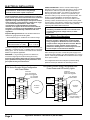
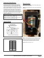
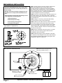
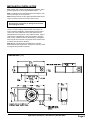
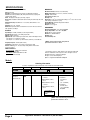
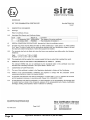
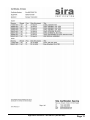
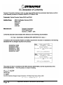
Headquarters: 1675 Delany Road • Gurnee, IL 60031-1282 • USA
Visit us at www.dynapar.com
Customer Service:
Tel.: +1.800.873.8731
Fax: +1.847.662.4150
[email protected]
Technical Support
Tel.: +1.800.234.8731
Fax: +1.847.782.5277
[email protected]
Encoder Installation Manual
NorthStar™ brand
SERIES EN44
Zone 1 “Hazardous Area” Rated Encoder
Document No.: 702828-0001
Revision Level: A
April. 2, 2012
Ex ia mb e IIC T4 Gb
Certification No.
Sira 09ATEX5172X
0518
General
Application Environment
The following instructions are meant to assist in proper
installation of the NorthStar Series EN44 Sealed
Hubshaft Encoder. The encoder is a harsh-duty speed
and position transducer that when mounted to a rotating
shaft, produces output pulses that are directly proportional to the shaft speed and direction. The encoder is
attached to the motor shaft via a stainless steel flexible
coupling that compensates for motor shaft end-play and
run-out. The clamp is also electrically isolated from the
encoder to ensure motor shaft currents do not ground
through the encoder bearings. Due to this specialized
coupling, special precautions must be taken during
installation as outlined in this manual.
The EN44 is uniquely designed with the primary protection technique as Encapsulation.
The EN44 was designed specifically for “Hazardous
Area” rated applications common in Oilfield operations.
Proper operation is dependant upon installation by
suitably trained personnel in accordance with the applicable code of practice.
Care should be taken to inspect the shipping container
and product for external damage and/or missing parts. If
any is found, contact Dynapar immediately as well as the
shipping agent.
Tools Required for Installation
Tool
Caliper & Dial Indicator Gages
1/4" Hex Key Wrench
5/32" Ball End Hex Key Wrench
Purpose
Shaft Checks
Shaft Clamp Access Plug
Shaft Collar Clamp and Shaft
Clamp Alignment Screw
3/16" Hex Key Wrench
Encoder Mounting Screws
10mm Hex Key Wrench
Stopping Plug
Open End Adjustable Wrench
Cable Gland
7/64" Hex Key Wrench
Terminal Box Cover
1/8" Flat Blade Screwdriver
Terminal Block Wiring
Torque Wrench, 20–75 inch pound range Tightening Fasteners
Threadlocker, Loctite 242 or equivalent Retaining Fasteners
The encapsulated electronics and increased safety
interface allow for use in Zones 1 and 2 with flammable
gases and vapors with apparatus groups IIA, IIB & llC
and with temperature classes T1, T2, T3, and T4. The
equipment is only certified for use in ambient temperatures in the range –50°C to 100°C.
Compliance with the Essential Health and Safety Requirements has been assured by compliance with the
following documents:
EN 60079-0:2006 (General)
IEC 60079-0:2007 (General)
EN 60079-7:2007 (Increased Safety)
EN 60079-18:2004 (Encapsulated)
Before installation or operating in a “Hazardous Area”, the
installer must be trained and familiar with hazardous area
installation and IEC/EN 60079-14 standards.
Note: Encapsulation techniques are an improvement over "flameproof" 60079-1 Specifications
requiring heavy XP metal enclosures to contain
a flame. Encapsulation eliminates the air around
the electronics preventing ignition and allowing
smaller lightweight enclosures to be used in the
design.
Table of Contents
Topic
Page
Description & Table of Contents ............................. 1
Electrical Installation ........................................... 2-3
Mechanical Installation ........................................4-5
Specifications ......................................................... 6
SIRA User Instructions ........................................... 7
SIRA Certification ............................................. 8-11
Declaration of Conformity ..................................... 12
Application Assistance 1.800.234.8731 (847.662.2666)
Page 1
ELECTRICAL INSTALLATION
CAUTION: Before installation, ensure power is off
and locked out. Failure to do so may damage
encoder and/or cause a spark or explosion.
Electrical Installation must be performed by an individual
that is trained and familiar with hazardous area installation.
Standards that apply are IEC/EN 60079-14 and other
applicable wiring codes that apply to the specific location
of the installation. Please follow the guidelines for a type
“e” Increased Safety Installation. Other cable
considerations include flammability, temperature,
chemical, etc as applies to the area and environment of
installation. If in doubt see the IEC/EN60079-14 standard
as applies to Increased Safety installations and local
regulations.
Important Wiring Instructions: Use shielded cable with a
defined wire gauge per the following table.
* Terminal blocks type ‘e’ certified for the conductor range:
Connectable Conductor Cross Section
Rigid/Soild Wire mm2 (AWG)
Flexible/Stranded Wire mm2 (AWG)
0.14 - 2.5 (26-14)
0.14 - 1.5 (26-16)
Consider the length of cable and desired drive currents for your
application. Consider a 0.5mm2 or 20AWG cable as a minimum
starting point. You can increase or decrease the wire diameter
based on your specific application.
SHIELDING – It is good wiring practice for a shield to be
connected to signal-ground at the receiving device only.
Connecting the shield at both ends can cause grounding
(loops) problems that degrade system performance and
give a path for stray currents to travel.
EN Series Encoder Wiring Configuration
with Fused Power
CABLE PROTECTION - Run the encoder cable through a
dedicated conduit (not shared with other wiring). Use of conduit
will protect the cable from physical damage and provide a
degree of electrical isolation. If a conduit is not practical use
wire trays to protect cable. If there is not a practical way to
protect the cable you may consider using armored cable - See
section 9 of the IEC/EN60079-14 standard as applies to
Increased Safety installations. Do not run the cable in close
proximity to other conductors that carry current to heavy loads
such as motors, motor starters, contactors etc. This practice can
induce electrical transients in the encoder cable, potentially
interfering with reliable data transmission.
CAUTION: Unused encoder signal wires must be
individually insulated and under no circumstances be
in contact with ground, voltage sources, or other
signal lines.
Zone 1 Wiring Considerations
CAUTION: The Encoder wiring configuration for the
EN series encoder is different than an Intrinsic Safe
wiring configuration. No IS barrier, Zener or Galvanic,
is required when using the EN series encoder. Barriers
may prevent proper operation and/or frequency
performance. Damage to the encoder may occur if the
encoder output is connected to an IS barrier.
When selecting an encoder, consider the power supply to the
encoder and input voltage to your data acquisition, PLC or drive
system. Cable length and RPM max will determine which output
driver option to select.
The configurations below are examples of protected wiring
practices and help to determine the best wiring scheme.
EN Series Encoder Wiring Configuration with
Fused Power and LED activity Lights
LED/Fused
Power Terminal Block
200mA max Suggested
LED/Fused
Power Terminal Block
200mA max Suggested
Power
Supply
+
-
Acquisition
A
System
AB
BZ
Z-
Page 2
Typ - Standard
Terminal Block
Power
Supply
+
Typ - Standard
Terminal Block
EN Series
Encoder
Acquisition
A
System
A-
EN Series
Encoder
B
BZ
Z-
Application Assistance 1.800.234.8731 (847.662.2666)
LED/Fused
Terminal Block
No Fuse Installed - for
Indicator LED Only
Cable Entry & Gland Selection
This product is supplied with dual 3/4” NPT entry holes for
wiring to the terminal block. SPECIAL CONDITIONS FOR
SAFE USE (denoted by X in the certificate number) require
cable entry to be fitted with an ATEX certified Type “e” cable
gland. Any gland certified for use as Type “e” and matching the
cable selected and designed to fit a 3/4” NPT can be used.
Wiring Procedure
Step 1: Remove terminal box cover. Assemble cable & gland
per manufactures instructions.
Step 2: Strip cable jacket back 3 inches. Strip individual leads
back 0.35”.
If ordered from Dynapar with no gland, customer must supply
an appropriate gland. If ordered with one of our available
glands, proper manufacturers assembly instructions must be
followed. Refer to HAWKE assembly instructions included with
your product, or locate and reference them on the HAWKE
website: www.ehawke.com.
Dynapar Available Glands. (ref. page 6 “Ordering Information” – Code 5)
Code 1: Non-Armored Cable – HAWKE 501/421 A 3/4” NPT S
Assembly Instruction: A1 307 / Issue M – 11/08
Code 2: Armored Cable – HAWKE 501/453/UNIV A 3/4” NPT
Assembly Instruction: A1 300 / Issue M – 11/08
Signal and Wiring
WAVEFORMS
DATA AND INDEX
Not all complements shown
A shown for reference
(180° ELEC
(90° ELEC)
Data A
Data A
Data B
Index
A leads B, CCW (From Clamp End)
ELECTRICAL CONNECTIONS
Encoder
Function
Terminal Box
Connection
Sig. A
1
Sig. A
2
Sig. B
3
Sig. B
4
Sig. Z
5
Sig. Z
6
Power +V
7
Com
8
Step 3: Wire to terminal block using pin assignment on this
page or on the inside of terminal box cover. Carefully press a
1/8" flat blade screw-driver into the inboard hole to open
terminal. Insert wire completely and remove screwdriver.
Step 4: Replace terminal box cover.
Application Assistance 1.800.234.8731 (847.662.2666)
Page 3
MECHANICAL INSTALLATION
STEP 1: Please reference the below diagram titled "EN 44
Motor Mount Requirements" to ensure that a correct
mounting interface is provided for the mechanical installation of this encoder. The EN44 has a 0.110 inch piloted face
that is concentric with the Flex Coupling. Be sure to create a
concentric pilot with the six 1/4-20 inch threaded holes on
customer equipment as shown in the diagram.
CAUTION: Upon initial inspection of the shaft coupling area of the EN44 you will notice a 10-32 screw
that extends through the encoder body and into the
shaft coupling.
DO NOT remove this Coupling Locating Screw until
directed to do so in Step 9 of the Installation Procedure.
STEP 2: Ensure the mounting interface and shaft extension are
free of dirt, grease, or any other foreign matter. Check the
shaft Total Indicated Run-out (TIR), and ensure that it does not
exceed 0.005” TIR.
Please familiarize yourself with the following as seen
in the magnified view drawing below:
1. Shaft Clamp Screw
STEP 3: Using the 1/4” hex key, remove the Shaft Clamp
Access Plug from the side of the encoder body.
2. Shaft Clamp Access Plug
3. Flex Coupling Locating Screw
STEP 4: Place the 5/32” ball end hex key into the access hole
and loosen the Shaft Collar Clamp Screw. Place a small
amount of threadlocker on the screw threads and re-install it
into the Clamp Collar. Re-thread the screw into the clamp
loosely. DO NOT TIGHTEN. Remove the 5/32” ball end hex
key from the access hole.
4. Coupling Locating Hole
Note: The encoder can be mounted on shafts of varying
lengths (MIN 0.47 in, MAX 0.83 in).
EN44 MOTOR MOUNT REQUIREMENTS
STEP 5: Place a Lockwasher onto each 1/4-20 x 1” Encoder
Mounting Screw (6 required). Apply a small amount of
threadlocker to the screw threads.
+.005
3.345
-.000
PILOT
STEP 6: While observing the proper orientation of the cable
exit, slide the encoder straight over the motor shaft extension,
and engage the encoder's Flex Coupling. Note again, shaft
engagement is MIN 0.47" MAX 0.83".
16MM OR
5/8" SHAFT
.110 MIN.
PILOT DEPTH
.47 MIN. TO
.83 MAX.
SHAFT LENGTH
6X 1/4-20 X
EQUALLY SPACED ON
A 3.937 B.C.
0.70 MIN.
EN44 COUPLING/CLAMP INSTALLATION
Note: Please refer to this figure when
performing Installation Steps 7 – 11.
1 SHAFT
CLAMP SCREW
2 SHAFT CLAMP
ACCESS PLUG
3
Page 4
4
COUPLING
LOCATING HOLE
FLEX COUPLING
LOCATING SCREW
Application Assistance 1.800.234.8731 (847.662.2666)
MECHANICAL INSTALLATION
Note: Please refer to ‘EN44 Coupling/Clamp Installation” figure
(previous page) when performing Installation Steps 7 – 11.
STEP 7: Install the six Encoder Mounting Screws using the 3/16”
hex key and torque to 75 inch pounds.
STEP 8: Using the 5/32” hex key, tighten the Shaft Clamp Screw.
Torque to 36 inch pounds. Remove the 5/32” hex key.
CAUTION: The motor shaft must NOT be rotated until
Step 9 (below) is performed, or damage to the encoder
flex coupling will result.
STEP 9 Using the 5/32 hex key, completely remove the
10-32 x 1.5” Flex Coupling Location Screw. This screw is no
longer needed for installation, instead replace with the shorter
10-32 x 7/8" screw. Obtain the 10-32 x 7/8” SHCS from the
hardware kit (this screw has an o-ring under the head). Apply a
small amount of threadlocker to the screw threads. Using the
5/32” hex key install the screw into the Coupling Locating Hole
and torque to 20 inch pounds. The purpose of this shorter screw
is to block the hole while in operation.
STEP 10 Apply a small amount of threadlocker to 1/8” NPT
Shaft Clamp Access Plug threads. Using the 1/4 hex key, install
the plug and torque to 60 inch pounds.
DIMENSIONS
mm
[inch]
Application Assistance 1.800.234.8731 (847.662.2666)
Page 5
SPECIFICATIONS
STANDARD OPERATING CHARACTERISTICS
MECHANICAL
Code: Incremental
Resolution: to 2048 PPR (pulses/revolution) See Ordering Information
Format: Two channel quadrature (AB) with optional Index (Z, ungated), and
complementary outputs
Index: 180 degrees ±18 degrees (electrical), ungated
Phase Sense: A leads B for CCW shaft rotation viewing the shaft clamp end of the
encoder
Quadrature Phasing: 1200 PPR: 90° ± 15° electrical; 2048 PPR: 90° ± 30°
electrical
Symmetry: 180° ± 18° electrical
Waveforms: Squarewave with rise and fall times less than 1 microsecond into a
load capacitance of 1000 pf
Mechanical Interface: Stainless steel shaft clamp
Mating Shaft Length: 0.47” to 0.83” (11.9mm to 28.1mm)
Coupling: 16mm, flexible
Shaft Speed: 6000 RPM, max.
Bearings: 6107
Bearing life: 5 x 10⁸ revs at rated shaft Loading, 5 x 10¹¹ revs at 10% of rated
shaft loading. (manufacturers’ specs)
Housing Material: Aluminum Alloy, Black Anodized
Disc material: Mylar®
Weight: 6 lb. 6 oz, typical
ELECTRICAL
Input Voltage: 7-15VDC, 7-26VDC (see ordering information)
Input Current: 65mA max., not including output loads
Outputs: TC4428 Line Driver
Output Current: (Refer to Ordering Information Table, Code 4: ATEX Output Format)
Code 4 Option 0 or 2: 125mA max. per channel
Code 4 Option 1 or 3: 10mA max. per channel @ 100°C; 15mA max. per channel @ 90°C
Frequency Response: 125 kHz (data & index)
Termination: Terminal block - Ex screwless w/spring cage-clamp
Interface: HAWKE type “E” increased safety rated gland for armored and
non-armored cables.
HAWKE Part Numbers:
Non-Armored Gland: HAWKE 501/421 A 3/4” NPT S
(accepts 8.5 - 13mm cable, OD)
Armored Gland: HAWKE 501/453 UNIV A 3/4” NPT
(accepts 12.5 - 20.5mm cable, OD)
ENVIRONMENTAL
Operating Temperature: -50 to 100°C. See †Note
Storage temperature: -50 to 100°C. See †Note
Shock: 50G’s for 11msec duration
Vibration: 5 to 2000Hz @ 20 G’s
Humidity: 100%
Enclosure Rating: IP67
† Note: Armored Gland high-temperature
specification limited to +80°C.
* Specifications subject to change without notice. All product and brand
names are trademarks of their respective owners. All rights reserved.
NorthStar™ brand is a trademark of Dynapar.
All rights reserved. © 2012 Dynapar
Mylar® is a registered trademark of Dupont
Models
Ordering Information
To order, complete the model number with code numbers from the table below:
Code 1: Model
Code 2: PPR
Code 3: Bore Size
Code 4: ATEX Output Format
Code 5: Termination
EN44
Ordering Information
EN44
ATEX Zone 1
Hubshaft Encoder
1024
2048
A 16mm
0 Differential AB, 7-15V in,
7-15V out
1 Differential AB, 7-26V in,
5V out
2 Differential ABZ, 7-15V in,
7-15V out
3 Differential ABZ, 7-26V in,
5V out
0 No Gland
1 Ex Gland for
non-armored
cables
(8.5 - 13.5mm OD)
2 Ex Gland for
armored cables
(12.5 - 20.5mm OD)
See †Note
* See Electrical
Specifications for
Details
† Note: Armored Gland high-temperature
specification limited to +80°C.
Page 6
Application Assistance 1.800.234.8731 (847.662.2666)
SIRA USER INSTRUCTIONS
1. The certification marking is as follows:
* Temperature ratings - The equipment is only certified for use in
an ambient temperature range -50°C to +100°C.
* The encoder is rated at IP54 for certification purposes. In
order to achieve this level of protection, appropriate ATEX
certified type ‘e’ Glands or Plugs must be used by the end user.
The thread form of the cable entries is 3/4 NPT.
2. The equipment may be used in Zones 1 and 2 with
flammable gases and vapours with apparatus groups IIA,
IIB & IIC and with temperature classes T1, T2, T3 and T4.
3. The equipment is only certified for use in ambient
temperatures in the range -50°C to +100°C and should not
be used outside this range.
4. The certificate number has an ‘X’ suffix, which indicates
that the certificate contains one of more special conditions
for safe use. Those installing or inspecting the equipment
should refer to this section of the certificate.
5. The equipment has not been assessed as a safetyrelated device (as referred to by Directive 94/9/EC Annex
II, clause 1.5).
6. The equipment has not been assessed as a safetyrelated device (as referred to by Directive 94/9/EC Annex
II, clause 1.5).
* Terminal blocks type ‘e’ certified for the conductor range:
Connectable Conductor Cross Section
0.14 - 2.5 [26-14] 0.14 - 2.5 [26-14]
Rigid [mm2] (AWG)
Flexible [mm2] (AWG)
0.14 - 1.5 [26-16] 0.14 - 2.5 [26-16]
MAINTENANCE ISSUES
* Periodic inspections should be made to ensure that there is
not excessive play in the encoder shaft due to bearing wear or
damage.
Additional documentation provided with each unit:
* Sira Certificate
* Installation, NonBarrier #200872-0001
PREPARATION:
Disconnect power from equipment and encoder cable.
7. Installation of this equipment shall be carried out by
suitably-trained personnel in accordance with the applicable code of practice.
Note: Ensure that pipe-thread tape or equivalent sealer is
applied to the conduit entry stopping plug and mating cable
gland for proper sealing.
8. Repair of this equipment shall only be carried out by the
manufacturer or in accordance with the applicable code of
practice.
Position the anti-rotation arm at a 90 degree angle (Ideal) to the
motor shaft.
9. The certification of this equipment relies on the following
materials used in its construction:
Enclosure: Case material type - Anodized aluminium.
Other external parts and Shaft material: Aluminium or
SST.
Potting Compounds: Silicone Based
Sealing Orings: Silicone type
Shaft seals: Viton
If the equipment is likely to come into contact with aggressive substances, then it is the responsibility of the user to
take suitable precautions that prevent it from being
adversely affected, thus ensuring that the type of protection
is not compromised.
This orientation ensures:
* Minimal housing rotation and encoder error caused by relative
motion.
* Reduced misalignment of bearing rod ends to prevent binding
and premature wear due to high degrees of misalignment.
Do not disrupt the anti-rotation arm’s 90° alignment with the
motor shaft during mounting. A parallel orientation between the
anti-rotation arm and the motor shaft is not recommended
because it will significantly reduce the anti-rotation arm’s
performance and operational lifetime. Each rod end can
withstand only 50° of deviation. Ideally, the anti-rotation arm
should be mounted with rod-end ball centered in its socket.
Recommended torque: 20 FT-LBS. [27 N-m].
“Aggressive substances” -e.g. acidic liquids or gases that
may attack metals, or solvents that may affect polymeric
materials.
“Suitable precautions” - e.g. regular checks as part of
routine inspections or establishing from the material’s data
sheet that it is resistant to specific chemicals.
Application Assistance 1.800.234.8731 (847.662.2666)
Page 7
Page 8
Application Assistance 1.800.234.8731 (847.662.2666)
Application Assistance 1.800.234.8731 (847.662.2666)
Page 9
Page 10
Application Assistance 1.800.234.8731 (847.662.2666)
Application Assistance 1.800.234.8731 (847.662.2666)
Page 11
Page 12
Application Assistance 1.800.234.8731 (847.662.2666)