Transcript
Li-Po Battery Deep Discharge Protector
HW-SM821DUL-20120607
User Manual of 2S Li-Po Battery Deep Discharge Protector
(For Remote Control Model Cars and Trucks)
1.
Features
The protector concentrates three functions in one unit: Deep discharge supervision and protection; Battery
voltage measurement; Abnormal throttle signal supervision and lose-control protection.
1.1.
Deep discharge supervision and protection:
7KH SURWHFWRU SURYLGHV UHOLDEOH SURWHFWLRQ IURP WKH ³GHDGO\´ GHHS GLVFKDUJH IRU \RXU SUHFLRXV /L-Po battery
cells. It can take not only the total voltage of whole battery pack but also the voltage of each cell, so it can
prevent the weakest cell from being damaged earlier than the other cell in the same battery pack. When the
voltage is lower than the threshold, the protector will stop the motor.
1.2.
Voltage measurement:
There are 3 LEDs on the protector to indicate the voltage of your battery pack.
2.5.
Specifications
Size: 32mm * 18mm * 9mm (L * W * H)
Weight: 5g
Battery type: 2S Li-Po
Threshold for deep discharge protection ˖2.6V/cell, 2.85V/cell or 3.1V/cell
(Correspondingly, the total threshold for a 2S Li-Po battery pack is 5.2V, 5.7V or 6.2V)
Tolerance˖0.05V
3.
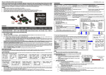
3.1.
Wiring
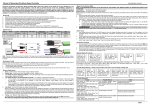
Application #1 (For Li-Po battery pack WITH a balance discharge connector)
Plug into the throttle channel
of the receiver
Plug the balance charge connector
of battery pack into the socket on
the protector
Signal In
LED
Group A
2S Li-Po
Battery Pack
+
-
ĺ
Ĺ
Wiring sequence is: ķ - ĸ - Ĺ - ĺ
LED
Group B
ķ
Button
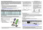
Application #2 (For Li-Po battery pack WITHOUT a balance discharge connector)
Plug into the throttle channel
of the receiver
Use the attached cable (accessories)
to connect the protector with the
output wires of battery pack
Signal In
LED
Group A
2S Li-Po
Battery Pack
LED
Group B
Ĺ
+
-
ķ
Button
Receiver
ĸ
Signal Out
Speed
Controller
Motor
Wiring sequence is: ķ - ĸ - Ĺ
ʿ1˄Red˅ ʿ2˄Green˅ ʿ3˄Green˅
LEDs in Group A
When the voltage is more than 7.8V, all of these 3 LEDs light;
When the voltage is between 7.8V to 7.0V, ʿ1 and ʿ2 LEDs light;
When the voltage is between 7.0V to the preset threshold, only ʿ1 LED lights;
When the voltage is lower than the preset threshold, none of these LEDs lights;
1.3.
Abnormal throttle signal supervision and lose-control protection:
The protector will continuously monitor the throttle signal. When the throttle signal from receiver is normal, the
protector will just transfer this signal to the speed controller (Pass this signal to the speed controller without any
modification). If the throttle signal from receiver is abnormal, the protector will automatically lock the signal to
the controller DW D VSHFLDO OHYHO \RX SUHVHW :H FDOO LW ³3URWHFW 3RLQW´ SOHDVH UHDG VHFWLRQ IRU GHWDLO
information).
* Remark: This function is only valid for AM, FM/PPM receiver, not valid for PCM receiver.
2.
2.1.
2.2.
2.3.
2.4.
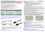
3.2.
Receiver
ĸ
Signal Out
Speed
Controller
Motor
LED
Group A
Button
Definition of Pins
LED
Group B
Pin 1
Pin 2
Pin 3
GND (Connect with Black wire)
ˇ5V Output (Connect with Red wire)
Control Signal (Connect with White or Orange wire)
4.
How to use the protector
4.1.
Connect the protector with your receiver and speed controller
There are 2 ways to use the protector.
Application #1: Monitor the voltage of each Li-Po cell. In such a case, you should plug the
balance charge connector of the battery pack into the socket of the protector. Please make sure
that you connect these equipments in the correct sequence: Before you plug the balance charge
connector into the socket on the protector, you should firstly connect the main output wires of
battery pack to your speed controller.
Application #2: Monitor the total voltage of the Li-Po battery pack. In such a case, you should use
the special cable to connect the battery pack with the protector in parallel. (The special cable is an
accessory of the protector; you can find it in the packing plastic bag)
4.2.
Set the threshold for deep discharge protection
The threshold is indicated by 3 LEDs in Group B. You can press the button beside the LEDs to change the
threshold.
4.3.
6HWWKH³3URWHFW3RLQW´IRUDEQRUPDOWKURWWOHVLJQDO
The abnormal throttle signal is often caused by failure of your receiver, over-distance or strong electromagnetic
interference, and etc. Usually this position (Protect Point) locates in the neutral range or brake range of throttle
channel.
Turn on your transmitter, and move the throttle stick to the position where you expect the speed controller will
get the control signal according to this position when the throttle signal from receiver is abnormal, and then
plug the balance charge connector of battery pack into the socket of the protector, the protector will get the
SRZHUVXSSO\DQGEHJLQWRZRUNWKH/('VZLOOV\QFKURQRXVO\IODVKWLPHVWKDWPHDQVWKH³3URWHFW3RLQW´
setting is completed.
,IWKHUHLVQ¶WEDODQFHFKDUJHFRQQHFWRURQ\RXUEDWWHU\SDFNSOHDVHFRQQHFWWKHVSHFLal cable (you can find it in
the packing plastic bag) with the battery pack in parallel, and then plug it into the socket of the protector, so the
protector can get the power supply from this socket.
2