1
This user manual describes all proceedings concerning the
operations of this CNC system in detail as much as possible. However, it is
impractical to give particular descriptions for all unnecessary or unallowable
system operations due to the manual text limit, product specific applications
and other causes. Therefore, the proceedings not indicated herein should
be considered impractical or unallowable.
This user manual is the property of GSK CNC Equipment Co., Ltd.
All rights are reserved. It is against the law for any organization or individual
to publish or reprint this manual without the express written permission of
GSK and the latter reserves the right to ascertain their legal liability.
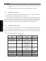
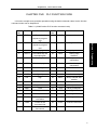
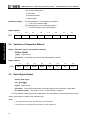
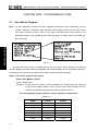
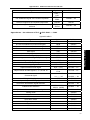
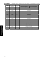
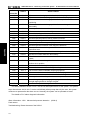
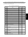
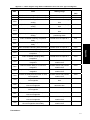
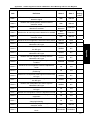
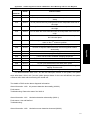
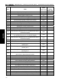
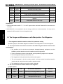
This User Manual is suitable for the following CNC systems
manufactured by GSK CNC EQUIPMENT CO., LTD.
GSK218MC Series
Series No.
GSK218MC
Machining Center CNC System
LED
PLC & Installation Connection Manual
Product type
Structure
GSK218MC
Integral
10.4
LED dimension is 10.4 inch by default
GSK218MC-U1
Integral
8.4
LED dimension is 8.4 inch by default
GSK218MC-H
Horizontal
8.4
LED dimension is 8.4 inch by default
GSK218MC-H2
Horizontal
10.4
LED dimension is 10.4 inch by default
GSK218MC-V
Vertical
10.4
LED dimension is 10.4 inch by default
dimension
Remark
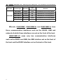
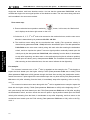
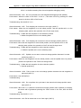
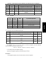
Wherein, GSK218MC, GSK218MC-H and GSK218MC-V have
three communication interfaces such as the RS232, USB and
network of which these interfaces are set on the front of the host.
GSK218MC-U1 owns only two communication interfaces
such as the RS232 and USB; the USB interface set on the front of
the host and the RS232 interface set on the back of the host.
II
Preface & Precaution
PREFACE
Your Excellency,
It’s our pleasure for your patronage and purchase of this
GSK218MC Series Machining Center CNC System made by GSK CNC
Equipment Co., Ltd.
This manual is the part of the “PLC and Installation Connection
Manual” of Machining Center CNC System User Manual for
GSK218MC Series, which is introduced its programming method and
installation connection
In order to guarantee the product is operated with a safe, normal
and effective situation, it is necessary to carefully read this manual
before installing and using this product.
Chinese version of all technical documents in Chinese and
English languages is regarded as final.
III
GSK218MC Series
Machining Center CNC System
PLC & Installation Connection Manual
SECURITY PRECAUTION
Accident may occur by improper operation! This system
only can be operated by authorized and qualified personnel.
Especial prompt: The system power installed on (inside) the
cabinet is the special-purpose one made by GSK CNC system.
Never attempt to use for other purposes by this power. Otherwise,
tremendous hazard may occur!
IV
Preface & Precaution
STATMENT!
警告、注意和注释的说明
z In this manual we have tried as much as possible to describe all
various matters. However, we cannot describe all the matters which
must not be done, or which cannot be done, because there are so
many possibilities. Therefore, matters which are not especially
described as possible in this manual should be regarded as
“impossible”
WARNING!
z Thoroughly read this manual and user manual issued by the machine
manufacturer, and strictly operate the machine based upon the
requirement of this manual before installing, programming and
operating the machine; otherwise, possibly causing damage to the
product, machine itself, as well the obsolete workpiece or injury to the
user.
V
GSK218MC Series
Machining Center CNC System
PLC & Installation Connection Manual
NOTICE!
z The product functions and technical indexes (such as accuracy,
velocity) described in this manual are only directed against this
product. The CNC installed this product, the actual function
configuration and the technical capacity are determined by the
machine manufacturer; the function configurations of the CNC
machine and technical indexes are subjected on the manual issued
by the machine builder.
All specifications and designs are subject to change without notice.
VI
Preface & Precaution
SAFETY PRECAUTIONS
■ Transportation and Storage
z
Do not pile up the carton over 6 layers.
z
Do not climb, stand on the carton; do not place heavy objects on it.
z
Do not drag or move the products using the cables connected with the product.
z
Do not impact, scratch the panel and screen.
z
Avoid from the damp, the sunshine and the rain on the product carton.
■ Unpacking inspection
z
Check whether it is your purchased product after unpacking the carton.
z
Check whether the product is damaged during transporting.
z
Check whether the components are prepared or damaged comparing with the
packing list.
z
It is necessary to contact our company immediately if the product type is
inconsistent with the packing list, lack of accessories or damage in
transportation.
■ Wiring
z
The person who executes the wiring and inspection should have the
corresponding professional capacity.
z
The product should be reliably grounded, and its resistance should be less than
0.1Ω and can not be used the neutral conductor (zero cable) to replace the
ground wire.
z
The wiring should be correct and firm, otherwise, possibly causing the
malfunction in product or unexpected result.
z
The surge absorb diode connected with the product should be linked based upon
the described direction, otherwise, it may damage the product.
z
Before Inserting/pulling out the plug or opening the main cabinet of the product, it
VII
GSK218MC Series
Machining Center CNC System
PLC & Installation Connection Manual
is important to cut off the product’s power.
■ Inspection and maintenance
z
Cut off the power before inspecting and maintaining or changing the
components.
z
Check the malfunction when the short-circuit or overloading occurs. The
computer can be started after the malfunction is eliminated.
z
Do not power ON/OFF frequently for the product, if you want to turn on the
power again after power off, its interval time is 1min. at least.
VIII
Preface & Precaution
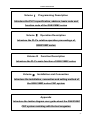
Volume Ⅰ
Programming Description
Introduce the PLC’s specification, address, basis code and
function code of the GSK218MC series
Volume Ⅱ
Operation Description
Introduce the PLC’s relative operation proceedings of
GSK218MC series
Volume III
Function Description
Introduce the PLC’s main function of GSK218MC series
Volume Ⅳ
Installation and Connection
Introduce the installation, connection and setting method of
the GSK218MC series CNC system
Appendix
Introduce the ladder diagram user guide about the GSK218MC
CNC system matching with the tool magazine
IX
GSK218MC Series
Machining Center CNC System
PLC & Installation Connection Manual
SECURITY RESPONSIBILITY
Security responsibility of the manufacturer
——Manufacturer should take responsibility for the design and structure danger of the
motor and the accessories which have been eliminated and/or controlled.
——Manufacturer should take responsibility for the security of the motor and
accessories.
——Manufacturer should take responsibility for the offered information and
suggestions for the user.
Security responsibility of the users
——User should know and understand about the contents of security operations by
learning and training the security operations of the CNC system.
——User should take responsibility for the danger because of increasing, changing or
modifying the original CNC system or accessories by themselves.
——User should take responsibility for the danger without following the operations,
maintenances, installations and storages described in the manual.
This manual is stored by the last user.
Sincerely thanks for your friendly supporting of GSK’s
products!
X
Content
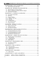
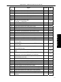
CONTENTS
VOLUME I
PROGRAMMING ............................................................................................ 1
CHAPTER ONE SQUENCY PROGRAMMING COMPILATION SCHEDULE ...... 2
1.1
1.2
1.3
1.4
1.5
GSK218MC Series PLC Specification ................................ 2
Concept of the Sequence Programming .............................. 2
Distribution Interface (Step one) ..................................... 3
Ladder Diagram Compilation (Step two) .............................. 3
Sequence Programming Debugging (Step 3) .......................... 3
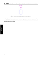
CHAPTER TWO SEQUENCE PROGRAMMING........................................................ 5
2.1 Performance Process of Sequence Programming ...................... 5
2.2 Cycle Performance ................................................ 6
2.3 Priority Sequence of the Execution (the 1st Level, the 2nd level) ............ 6
2.4 Sequence Program Structure ......................................... 7
2.5 Input/output Signal Treatment......................................... 9
2.5.1 Input Signal Treatment.............................................................................. 9
2.5.2 Treatment of the Output Signal ........................................................... 10
2.5.3 Distinguish of Signal State Between 1st Level and 2nd Program....... 10
2.6 Interlocking ...................................................... 11
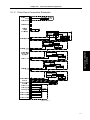
CHAPTER THREE PLC ADDRESS ............................................................................. 13
3.1 Machine → PLC address (X) ...................................... 13
3.1.1 X Address on I/O Input............................................................................ 14
3.1.2 X Address on MDI Panel......................................................................... 14
3.2 PLC → Address of Machine Tool Side (Y) ........................... 16
3.2.1 Y Address on I/O Output Port ................................................................. 16
3.3 PLC →CNC Address (G) .......................................... 18
3.4 CNC →PLC Address (F) .......................................... 19
3.5 Internal Replay Address (R) ........................................ 19
3.6 Nonvolatile Relay Address (K) ...................................... 20
3.7 Information Display Request Address (A) ............................ 20
3.8 Counter Address (C) .............................................. 21
3.9 Counter Preset Value Address (DC) ................................. 21
3.10 Timer Address (T) ............................................... 21
3.11 Presetting Value Address of Timer (DT) ............................. 21
3.12 Data Table Address (D)........................................... 21
3.13 Address Mark (L) ................................................ 21
3.14 Subprogram Number (P) ......................................... 22
CHAPTER FOUR PLC BASIS CODE........................................................................... 23
4.1 RD, RD.NOT, WRT, and WRT.NOT Codes ........................... 23
4.2 AND, AND.NOT Codes ............................................ 24
4.3 OR, OR.NOT Codes .............................................. 25
XI
GSK218MC Series
Machining Center CNC System
PLC & Installation Connection Manual
4.4 OR. STK Code .................................................. 25
4.5 AND. STK Code ................................................. 26
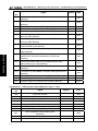
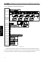
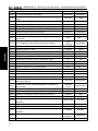
CHAPTER FIVE PLC FUNCTION CODE................................................................... 27
5.1
5.2
5.3
5.4
5.5
5.6
5.7
5.8
5.9
5.10
5.11
5.12
5.13
5.14
5.15
5.16
5.17
5.18
5.19
5.20
5.21
5.22
5.23
5.24
5.25
5.26
5.27
5.28
5.29
5.30
5.31
5.32
5.33
5.34
5.35
END1 (The 1st Level Sequence Program End) .......................
END2 (The 2nd Sequence Program End) ............................
CALL (Call Subprogram) ..........................................
CALLU (Unconditionally Call Subprogram) ..........................
SP (Subprogram) ................................................
SPE (End of Subprogram).........................................
SET (Replacement/Setting) .......................................
RST (Resetting) .................................................
JMPB (Mark Number Skip) ........................................
LBL (Mark Number) .............................................
TMR (Timer)....................................................
TMRB (Fixed Timer).............................................
TMRC (TIMER) .................................................
CTR (Binary Counter) ...........................................
DEC (Binary Decoding) ..........................................
COD (Binary System Code Conversion) ...........................
COM (Concentric Line Control) ...................................
COME (Concentric Line Control End) ..............................
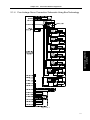
ROT (Binary Rotation Control) ....................................
SFT (Register Displacement/Shifting) ..............................
DIFU (Rising Edge Detection) ....................................
DIFD (Descending Edge Detection) ...............................
COMP (Comparison of Binary Number) ............................
COIN (Consistency Comparison)..................................
MOVN (Data Transmission) ......................................
MOVB (Transmission of 1 Byte)...................................
MOVW (Transmission of Two Bytes)...............................
XMOV (Binary Indexed Data Transmission) ........................
DSCH (Binary Data Index) .......................................
ADD (Binary Addition) ...........................................
SUB (Binary Subtraction) ........................................
ANDF (Bit-by-bit AND) ...........................................
ORF (Bit-by-bit OR) .............................................
NOT (Bit-by-bit NOT) ............................................
EOR (Exclusive OR) ............................................
28
28
28
29
30
30
31
31
32
33
33
34
35
36
38
39
40
41
41
44
45
46
47
48
48
49
50
51
52
53
54
55
56
57
58
CHAPTER SIX COMPILATION LIMIT OF LADDER DIAGRAM......................... 60
VOLUME II
OPERATION EXPLANATION ................................................................... 62
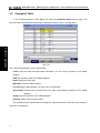
CHAPTER ONE PLC INTERFACE DISPLAY ........................................................... 64
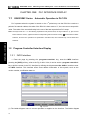
1.1 GSK218MC Series Automatic Operation in PLC ON................. 64
1.2 Program-Controlled Interface Display ............................... 64
XII
Content
1.2.1
1.2.2
1.2.3
1.2.4
1.2.5
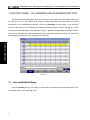
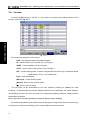
INFO Interface ........................................................................................ 64
PLCGRA Interface .................................................................................. 66
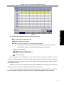
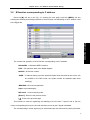
PLCPAR Interface................................................................................... 66
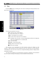
PLCDGN Interface .................................................................................. 67
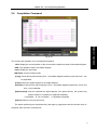
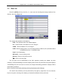
PLCTRAE Interface ................................................................................ 68
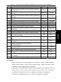
CHAPTER TWO PLC PROGRAMMING OPERATION........................................... 72
2.1
2.2
2.3
2.4
2.5
2.6
2.7
Brief ............................................................ 72
Basis Code ...................................................... 73
Operation Explanation of Ladder Diagram ........................... 74
Function Code ................................................... 77
Command Table .................................................. 78
Compilation Command ............................................ 79
PLC Operation Steps.............................................. 80
CHAPTER THREE PLC ADDRESS AND PARAMETER SETTING....................... 82
3.1
3.2
3.3
3.4
3.5
Nonvolatile/Hold Relay ............................................ 82
Timer ........................................................... 84
Data List......................................................... 85
Counter ......................................................... 86
M function corresponding to F address .............................. 87
CHAPTER FOUR USER EXPLANATION OF LADDER DIAGRAM SOFTWARE
EDIT..................................................................................................................................... 90
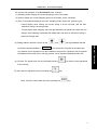
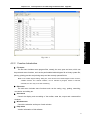
4.1 Brief ............................................................ 90
4.2 Software Introduction.............................................. 90
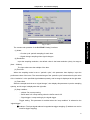
4.2.1 Software Start ......................................................................................... 90
4.2.2 Function Introduction .............................................................................. 91
4.3 Software Operation ............................................... 92
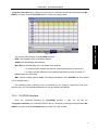
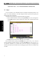
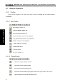
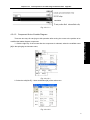
4.3.1 Toolbar
………………………………………………………………………92
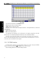
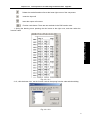
4.3.2 Selection of Figure .................................................................................. 94
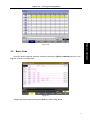
4.3.3 Editing of Figure...................................................................................... 95
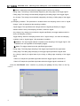
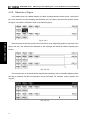
4.3.4 Ladder Diagram Note.............................................................................. 96
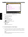
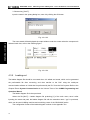
4.3.5 Leading-out............................................................................................. 98
VOLUME III
FUNCTION EXPLANATION ................................................................... 100
CHAPTER ONE CONTROLLABLE AXIS ................................................................ 102
1.1
1.2
Output of Axis Movement ......................................... 102
Servo Signal Ready .............................................. 103
CHAPTER TWO OPERATION PREPARATION..................................................... 104
2.1
2.2
2.3
2.4
2.5
ESP ........................................................... 104
CNC Overtravel Signal ........................................... 104
Alarm Signal .................................................... 105
Selection of Operation Method .................................... 106
State Signal Output .............................................. 106
XIII
GSK218MC Series
Machining Center CNC System
PLC & Installation Connection Manual
CHAPTER THREE MANUAL OPERATION............................................................ 108
3.1
JOG Feed/Incremental Feed ..................................... 108
CHAPTER FOUR REFERENCE POSITION RETURN........................................... 112
4.1 Manual Reference Position Return ................................ 112
4.2 Return to Reference Position Detection Signal ...................... 113
4.3 Area Detection Signal ........................................... 114
CHAPTER FIVE AUTOMATICAL OPERATION ................................................... 116
5.1 Cycle Start/ Feed Dwell .......................................... 116
5.2 Resetting ...................................................... 118
5.3 Program Testing ................................................ 119
5.3.1 Machine Tool Lock .................................................................................119
5.3.2 Dry Run …………………………………………………………………….119
5.3.3 Single Block .......................................................................................... 120
5.4 Skip Optional Block ............................................. 121
5.5 Program Restart ................................................ 122
CHAPTER SIX FEEDRATE CONTROL ................................................................... 124
6.1 Rapid Traverse Rate ............................................ 124
6.2 Feedrate Override............................................... 124
6.3 Override Cancellation............................................ 125
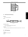
CHAPTER SEVEN MISCELLANEOUS FUNCTION .............................................. 126
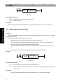
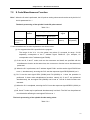
7.1 M Code Miscellaneous Function ..................................
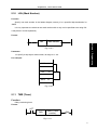
7.2 S Code Miscellaneous Function...................................
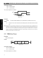
7.3 T Code Miscellaneous Function ...................................
7.4 Miscellaneous Function Lock .....................................
126
127
128
132
CHAPTER EIGHT SPINDLE VELOCITY FUNCTION.......................................... 134
8.1 Spindle Velocity Control Method................................... 134
8.1.1 Gear Spindle ......................................................................................... 134
8.1.2 Analog Spindle ...................................................................................... 134
8.2 Rigid Tapping................................................... 136
CHAPTER NINE PROGRAMMING CODE.............................................................. 138
9.1 User Macro Program ............................................ 138
9.2 Canned Cycle .................................................. 140
CHAPTER TEN DISPLAY/SETTING ........................................................................ 142
10.1 Clock Function ................................................ 142
10.2 Operation Record Display ....................................... 142
10.3 Help Function ................................................. 142
CHAPTER ELEVEN MEASURING ........................................................................... 144
11.1 Skip Function.................................................. 144
CHAPTER TWELVE PANEL LOCK SETTING ...................................................... 146
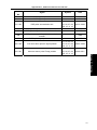
VOLUME IV
XIV
INSTALLATION & CONNECTION...................................................... 157
Content
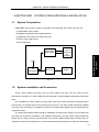
CHAPTER ONE SYSTEM CONFIGURATION & INSTALLATION .................... 159
1.1 System Composition ............................................. 159
1.2 System Installation and Connection ................................ 159
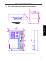
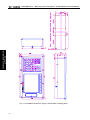
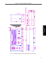
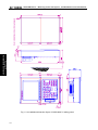
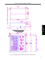
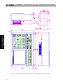
1.3 CNC System Appearance Installation Dimension Figure .............. 161
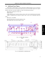
1.4 Additional Panel Figure ........................................... 167
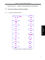
CHAPTER TWO CONNECTION BETWEEN EQUIPMENTS............................... 169
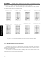
2.1 Connection Diagram of External System ............................ 169
2.1.1 Layout of Interface Position ...................................................................169
2.1.2 Pulse Servo Connection Schematic.......................................................171
2.1.3 Bus Servo Connection Schematic .........................................................172
2.1.4 Five-Linkage Servo Connection Schematic Using Bus Technology .......173
2.2 Connection Between System and Drive Unit......................... 174
2.2.1 System Interface Figure.........................................................................174
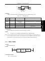
2.2.2 Interface Signal List ...............................................................................174
2.2.3 Signal Explanation .................................................................................175
2.2.4 Cable Connection Figure .......................................................................177
2.2.5 GSK-LINK Cable Connection Figure .....................................................179
2.2.6 External Wiring Figure of GL100 Bus Extension Module .......................181
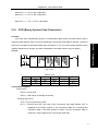
2.3 RS232 Standard Series Interfaces ................................. 182
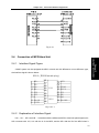
2.4 Connection of MPG/Hand Unit..................................... 183
2.4.1 Interface Signal Figure...........................................................................183
2.4.2 Explanation of Interface Signal ..............................................................183
2.5 Connection of Spindle Unit ........................................ 186
2.5.1 Interface Signal Table ............................................................................186
2.5.2 Explanation of Interface Signal ..............................................................186
2.5.3 Cable Connection Figure .......................................................................187
2.6 System Power Interface .......................................... 189
2.7 External Power Control Interface .................................. 189
2.8 Connection of Communication Cable ............................... 189
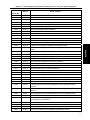
CHAPTER THREE I/O INTERFACE OF MACHINE CONTROL......................... 191
3.1 Interface Signal Table ............................................ 191
3.2 Interface Input................................................... 191
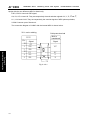
3.2.1 Interface Circuit Input.............................................................................191
3.2.2 Interface Circuit of Hand Unit.................................................................192
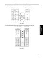
3.2.3 Interface Definition of Signal Input .........................................................193
3.3 Interface Output ................................................. 196
3.3.1 Interface Circuit Output ..........................................................................196
3.3.2 Interface Definition of Signal Output ......................................................197
CHAPTER FOUR MACHINE DEBUGGING ............................................................ 199
4.1 Debugging Preparation ........................................... 199
4.2 System Power-ON ............................................... 200
4.3 ESP and Limit ................................................... 200
4.4 Gear Ratio Adjustment ........................................... 202
XV
GSK218MC Series
Machining Center CNC System
PLC & Installation Connection Manual
4.5 Backlash Compensation ......................................... 204
4.6 Setting Related with Drive unit .................................... 205
4.7 Machine Tool Pitch Compensation................................. 206
4.8 Mechanical Zero Return (Machine Zero Return) ..................... 213
4.8.1 Mechanical Zero Return in Pulse Method ............................................. 214
4.8.2 Servo Zero Return Function Setting of Bus Type .................................. 217
4.9 Input/Output Signal Control of Spindle Positive/Negative ............. 223
4.10 Spindle Automatic Gear-shift Control ............................. 225
4.11 External Cycle Start & Feed Hold................................. 227
4.12 External Editing Lock and the External Operation Panel Lock ........ 228
4.13 Cooling, Lubrication and Chip-Removal Control .................... 228
4.14 Setting Related to Feedrate ..................................... 229
4.15 Setting Related with Tapping Parameter .......................... 231
4.16 Setting for the 4th Axis .......................................... 234
4.17 Setting About the Bus Servo..................................... 236
APPENDIX .......................................................................................................................... 243
APPENDIX I
LADDER DIAGRAM USAGE GUIDE OF GSK218MC SERIES WITH
CONE TYPE TOOL-MAGAZINE..................................................................................... 245
I. Cautions When Using the Cone Type Tool-Magazine Ladder Diagram .. 245
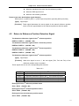
II. Configuration and Definition of PLC I/O Address and Internal Software
Components
…………………………………………………………………….245
III. The Usage and Maintenance of the Cone Tool Magazine.................... 270
IV. The Macro Note Matching with the Cone Tool Magazine..................... 278
APPENDIX II
LADDAR DIAGRAM USE GUIDE OF GSK218MC SERIES
MATCHING WITH DISC TOOL MAGAZINE................................................................. 281
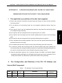
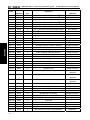
I. The application precautions of the disc tool magazine......................... 281
II. The Configuration and Definition of the PLC I/O Address and Internal Soft
Component
……………………………………………………………………281
III. The Usage and Maintenance with Manipulator Tool Magazine.............. 310
IV. Macro Note with Disk Tool Magazine ....................................................... 317
APPENDIX III
FILE FORMAT OF LADDER DIAGRAM CONFIGURATION........ 319
I. F Signal and Meaning of the M Code M00---M99....................................... 319
II. That the “%” Takes One Single Line Means that the M code Information
Storage is End
…………………………………………………………………….319
III. The Code and Meaning of the X Signal X0.0---X6.7 ................................ 319
IV. The Code and Meaning of the Y Signal Y0.0---Y5.7 ................................ 320
V. The Code and Meaning of the K Signal K6.0---K63.7............................... 320
VI. The Code and Meaning of the A Signal A0.0---A31.7 ........................... 320
VII. end//End Mark.....……………………………………………………………….320
XVI
VOLUME I PROGRAMMING
Volume I
Programming
1
GSK218MC Series
CHAPTER ONE
Machining Center CNC System
PLC & Installation Connection Manual
SQUENCY PROGRAMMING COMPILATION
SCHEDULE
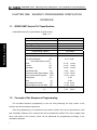
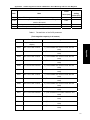
1.1
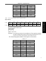
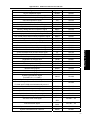
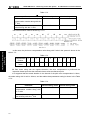
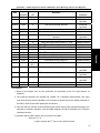
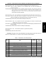
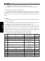
GSK218MC Series PLC Specification
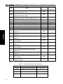
GSK218MC series PLC specification is shown below:
Table 1-1-1
Volume I Programming
Specification
GSK218MC Series PLC
Programming language
Ladder
Program level
2
The 1 level program execution cycle
8ms
Basis code average treatment time
5μs
Programming capacity
4700 steps
Code
Basis code + function code
st
Internal relay
(R)
PLC alarm detection
(A)
Nonvolatile memory area
Timer
(T)
Counter
Data base
Nonvolatile relay
Counter prevalue data register
Timer prevalue data register
Subprogram
Mark
Input signal of NC side
Signal outputs to the NC side
I/O module
(C)
(D)
(K)
(DC)
(DT)
(P)
(L)
(F)
(G)
(X)
(Y)
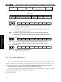
1.2
0~511 (byte)
0~31(byte)
0~127 (word)
0~127 (word)
0~255 (word)
0~63 (byte)
0~127(word)
0~127(word)
0~99
0~99
0~63(byte)
0~63(byte)
0~63 (byte)
0~47 (byte)
Concept of the Sequence Programming
The so-called sequence programming is the one that performing the logic control to the
machine tool and its relative equipments.
After the programming is converted into some kind of format, CPU can be performed its code
and calculation treatment for it, and its fruits can be memorized to RAM. CPU can be rapidly read
each code stored in the memory, which can be performed the programming according to the
calculation operation.
2
Chapter One
Squency Programming Compilation Schedule
The compilation of the sequence programming starts with the ladder diagram.
1.3
Distribution Interface (Step one)
The interface can be distributed after confirming the control object and calculating the points of
the corresponding input/output signal.
Refer to the Chapter Four Input/output interface signal table in the Volume Four Installation and
Connection when distributing the interface.
VolumeI I Programming
Programming
Volume
1.4
Ladder Diagram Compilation (Step two)
The required control operation can be expressed by the ladder diagram with the on-line
compilation of the Gsk218MC series ladder diagram. The functions, such as the timer and counter,
can not be expressed by relay symbols, which can be indicated by the specified function code
symbols.
The compiled ladder diagram should be stored and converted into the corresponding PLC
codes before operating, namely, the so-called instruction list.
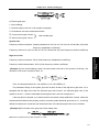
1.5
Sequence Programming Debugging (Step 3)
The sequence programming can be debugged using the following methods:
Debugging with emulator
The machine tool can be replaced by an emulator (it composes of the lights and switches).
ON/OFF of the switch means the signal input state of the machine tool, and the ON/OFF of
the light is the signal state output.
Debugging with actual operation
Debug on the actual machine tool. It is better to prepare the precautions before debugging,
otherwise an unexpected behavior may occur.
3
GSK218MC Series
Volume I Programming
4
Machining Center CNC System
PLC & Installation Connection Manual
Chapter Two Sequence Programming
CHAPTER TWO
SEQUENCE PROGRAMMING
The operation principle is different with the common relay circuit, because the PLC sequence
control is carried out by compiling the on-line diagram; and therefore, it is better to thoroughly
comprehend the sequence control principle when designing the PLC sequence programming.
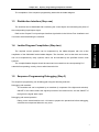
2.1
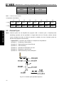
Performance Process of Sequence Programming
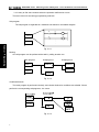
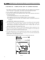
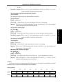
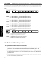
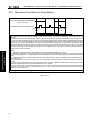
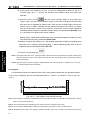
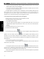
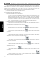
In the general relay controlling circuits, each of them can be simultaneously operated. When the
Volume I Programming
relay A is operated in the following figure, the replay D and E can be operated (when the contactor A
and B are entirely closed) at the same. Each replay in the PLC sequence control is operated in turn.
The relay D is operated before relay A, and then the relay E operates (refer to the following figure).
Namely, each relay is operated based upon the sequence of the ladder diagram (compilation
sequence).
A
B
D
A
C
E
Fig. 2.1 (a) Circuit illustration
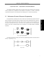
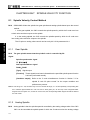
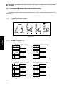
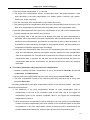
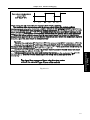
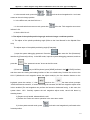
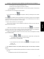
The differences between the relay circuit and PLC programming operation are shown below in
the Fig. 2.1 (b) and Fig. 2.1 (c).
A
C
B
A
C
Fig. 2.1 (b)
5
GSK218MC Series
Machining Center CNC System
PLC & Installation Connection Manual
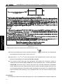
A
C
A
C
B
Fig. 2.1 (c)
(1) Relay circuit
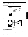
Both Fig. 2.1 (b) and Fig. 2.1 (c) are shared a same operation. B and C are switched on after A
is turned on. B is cut off after C is ON.
Volume I Programming
(2) PLC program
A same relay is shared a same circuit, refer to the Fig. 2.1 (b); B and C are switched on after A
is turned on. B is cut off after one cycle of the PLC program is performed. In the Fig. 2.1 (c), C is ON
instead of B, after C is turned on.
2.2
Cycle Performance
PLC performs from the beginning to the end of the ladder diagram. It performs again from the
beginning of the ladder diagram after this diagram is performed, which is called cycle performance.
The performance time from the beginning to the end of the ladder diagram is abbreviated as a
period of a cycle treatment. The shorter of the treatment period is, the stronger of the response
capacity of the signal is.
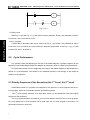
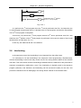
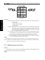
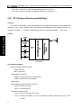
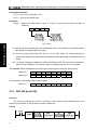
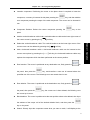
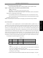
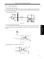
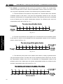
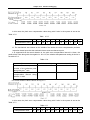
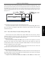
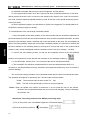
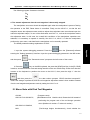
2.3 Priority Sequence of the Execution (the 1st Level, the 2nd level)
GSK218MC Series PLC program are composed of two parts: the 1st level program and the 2nd
level program, which are inconsistent with the performance period.
The 1st level program performs once each 8ms, which can be treated the short pulse signal
required for fast response.
The 2nd program performs once each 8*nms. N is the partition number of the 2nd level program.
PLC may divide the 2nd level program into N parts when the 2nd level program is executed. It is
performed one part for each 8ms.
6
Chapter Two Sequence Programming
Fig. 2-3-1
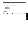
Volume I Programming
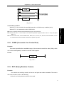
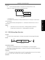
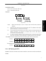
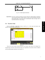
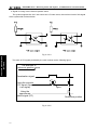
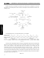
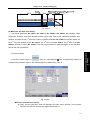
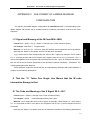
PLC in the GSK218MC series is separately performed in the PLC-AVR SCM. The 1ms of each
8ms is the communication time for reading the PLC data from the CNC. The 5ms is that the PLC
gains the system control signal (F, X), and uploads the control result data (G and Y parameters)
external port I/O (X and Y). PLC is always performed the ladder diagram calculation other than the
interruption of the response exchange data.
Fig. 2-3-2
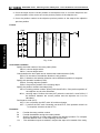
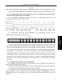
When the last partition number of the 2nd level program of the n is performed, the program then
executes from its beginning. In this case, when the partition number is n, the performance time of one
cycle is 8*n ms. The 1st level program performs once each 8ms; the 2nd level program performs once
each 8*n ms. If its steps of the 1st level program is increased, and therefore the steps of the 2nd level
program within 8ms should be reduced correspondingly; the partition number may be increased, and
the treatment time of the overall programs will be longer. So, the compilation of the 1st level program
should be shorter.
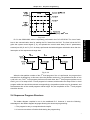
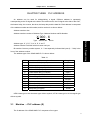
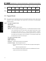
2.4 Sequence Program Structure
The ladder diagram compiles in turn in the traditional PLC. However, it owns the following
advantages in the ladder diagram language allowing the structured programming:
1. The program is easy to comprehend and compile.
2. It is more convenient to find the faults during the programming.
7
GSK218MC Series
Machining Center CNC System
PLC & Installation Connection Manual
3. It is easy to find some reasons when the operation malfunction occurs.
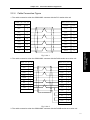
There are 3-kind of structuring programming methods:
Sub-program
The subprogram is regarded as a treatment unit based on the ladder diagram.
A
C
B
Task A
A
.
.
.
.
Task B
C
Volume I Programming
Fig. 2-4-1
Nesting
One subprogram can be performed the task by calling another one.
Main program
Task A
Subprogram 1
Task A1
Subprogram 2
Task A11
Task A12
Task B
Task An
Fig. 2-4-2
Conditional branch
The main program is performed circularly, and checks whether its conditions are suitable. If does,
perform the corresponding subprograms, vice versa.
Fig. 2-4-3
8
Chapter Two Sequence Programming
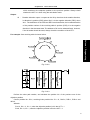
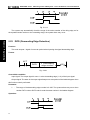
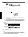
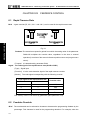
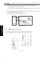
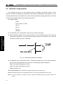
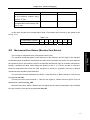
2.5 Input/output Signal Treatment
Input signal treatment:
Volume I Programming
Fig. 2-5-1
Output signal treatment:
CNC
CNC—PLC
PLC
Shared register
The 1st
level
program
The 2nd
level
program
Machine tool
input register
8ms
IO terminal
Fig. 2-5-2
2.5.1 Input Signal Treatment
(1) NC input register
The NC input signals from the NC are memorized into the NC input register, which are
transferred to PLC each 8ms. The 1st level program performs the corresponding treatment using
state of these signals.
(2) Machine tool input register
9
GSK218MC Series
Machining Center CNC System
PLC & Installation Connection Manual
The machine tool input register is scanned and memorized its input signal from the machine
each 8ms. The 1st level program is also performed the corresponding treatment by using this signals
directly.
(3) The 2nd level program input latch
The 2nd level program input signal latch is also called the 2nd level program synchronic input
signal register. Wherein, the stored input signal is treated by the 2nd level program. This signal state
in the register is synchronic with the 2nd level one.
The signals both in the NC and machine tool input latch can be locked to the 2nd level program
input latch, as long as the 2nd level program performs. The signal state in this latch keeps invariable
during the performance of the 2nd level program.
Volume I Programming
2.5.2
Treatment of the Output Signal
(1) NC output register
The output signal transfers to the NC output register from the PLC each 8ms.
(2) Machine tool output register
The signal memorized in the machine tool output register conveys to the machine tool each
8ms.
Note: The signal states, such as the NC input register, NC output register, machine input register and machine
output register, which can be displayed by the self-diagnosis function. The diagnosis number is the address
number in the sequence programming.
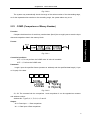
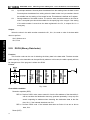
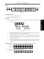
2.5.3
Distinguish of Signal State Between 1st Level and 2nd Program
As for the same input signal, their states may different between the 1st and 2nd level
programming, that is the reason that different registers are used between two levels programming.
Namely, the input signal used with the 2nd level program is the one of the 1st level who is locked. And
therefore, the signal in the 2nd level program is later than the 1st level one. At the worst case, one 2nd
level program performance cycle can be lagged.
It is better to remember this point when programming the ladder diagram.
10
Chapter Two Sequence Programming
A
A
.
.
.
.
END1
.
.
.
.
B
C
It belongs to the 2 nd partition
of the 2 nd level program
Fig. 2-5-3-1
A=1 performs the 1st level program when the 1st 8ms is performed, then B=1. And therefore, the
2nd level program is performed, the A=1 is latched to the 2nd level program, and then the first partition
of the 2nd level program is completed.
therefore, the 2nd partition of the 2nd level program is performed; in this case, the state of the A is still
latched as the one last time. So, C=1.
In this way, the state both B and C are different.
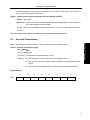
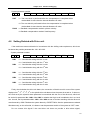
2.6
Interlocking
In the sequence control, the interlocking is very important from the safety issue.
It is necessary to use the interlocking in the sequence control programming. Simultaneously,
the hard interlocking is used in the relay control circuit of the strong electric cabinet of the machine
tool sides. This is the reason that the interlocking is disabled when the hardware of the performance
sequence programming malfunctions, even if the interlocking is logically used in the sequence
program (software). And therefore, the interlocking can be ensured the safety for the user, and
prevent the machine tool from damaging in the strong electric cabinet of the machine sides.
11
Volume I Programming
A turns into 0 to perform the 1st level program when the 2nd 8ms is performed, then B=0. And
GSK218MC Series
Volume I Programming
12
Machining Center CNC System
PLC & Installation Connection Manual
Chapter Three
PLC Address
CHAPTER THREE
PLC ADDRESS
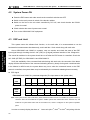
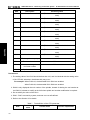
An address can be used for distinguishing a signal. Different address is separately
corresponding to the I/O signal at the side of the machine tool, the I/O signal at the side of the CNC,
the internal relay, the counter, the timer, the keep relay and the data list. Each address is composed
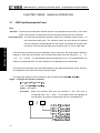
of the address number and bit number, and its number is as shown below:
Address number rules:
Address number consists of Address Type, Address Number and Bit Number.
X 000 . 6
Address No.
Bit No.
Address type: X, Y, R, F, G, K, A, D, C and T
Address number: Decimal number means one byte.
Bit number: Octonary number system, 0~7 are separately indicated the bytes (0~7 bits) in the
front of the address number.
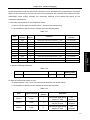
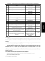
The address type of the GSK218MC PLC is shown below:
Table 3-1
Add.
Address explanation
Length
X
Machine →PLC (64 bytes)
INT8U
Y
PLC → machine tool (48 bytes)
INT8U
F
CNC → PLC (64 bytes)
INT8U
G
PLC → CNC (64 bytes)
INT8U
R
Intermediate relay (512 bytes)
INT8U
D
Data register (0~255)
INT16U
The data register of the counter preset value
INT16U
C
Counter (0~127)
INT16U
A
PLC alarm detection
T
Timer (0~127)
INT16U
The data register of the timer preset value
INT16U
Keep relay (64 types)
INT8U
DC
DT
K
INT8U
INT8U data type is 8-bit character type without symbol, INT16U data type is 16-bit integral type
without symbol.
3.1
Machine → PLC address (X)
The X address of the GSK218MC PLC composes of two types:
13
Volume I Programming
Type
GSK218MC Series
Machining Center CNC System
PLC & Installation Connection Manual
1. The X address is assorted with the three I/O input terminals, namely, XS40, XS41 and
XS42.
2. The X address is assorted with the input button on the MDI panel of the system.
3.1.1
X Address on I/O Input
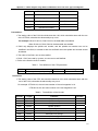
The addresses (48 addresses) are defined as INT8U from X0 to X5, which are distributed on
the three I/O input terminals, for example, XS40, XS41 and XS42.
Users can define the signal significance of the X address of the I/O ports based upon the actual
cases, which can be connected the machine tool and compiled the corresponding ladder diagram.
Volume I Programming
Refer to the appendix one (GSK218MC CNC system PLC I/O address) and the configuration and
definition of the internal software components for the initial definition of the input address.
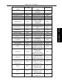
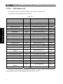
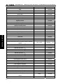
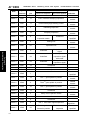
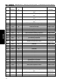
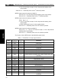
3.1.2
X Address on MDI Panel
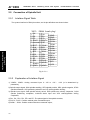
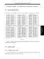
There are 11 types from the addresses X20 ~ X30 of which these addresses are corresponding
with the button input on the MDI panel one by one. User can not modify its signal definition. The
buttons on the MDI panel should be firstly responded by CNC, and then conveys the X signal to
PLC.
The corresponding relationships are shown below:
Table 3-1-2-1
Operation panel key
input
PLC add.
Operation panel key
input
PLC add.
Edith method
X20.0
Rapid switch
X24.7
Auto method
X20.1
F0/ 0.001
X26.0
MDI method
X20.2
F25%/ 0.01
(218MC-U1is the rapid
override addition)
X26.1
X20.3
F50%/ 0.1
(218MC-U1is the rapid
override 100%)
X26.2
Single step method
X20.4
F100%/ 1 (218MC-U1is
the rapid override
reduction)
X26.3
Manual method
X20.5
Manual feed axis +1st
X27.0
MPG method
X20.6
Manual feed axis +2nd
X27.1
DNC method
X20.7
Manual feed axis +3rd
X27.2
Skip
X21.0
Manual feed axis +Nth
X27.3
Single block
X21.1
N axis +(+ spindle
X27.4
Zero return method
14
Operation panel key
input
Chapter Three
PLC Address
PLC add.
Operation panel key
input
PLC add.
override 218MC
integration)
X21.2
Manual feed axis -1st
X28.0
Miscellaneous lock
X21.3
Manual feed axis -2nd
X28.1
Machine lock
X21.4
Manual feed axis -3rd
X28.2
Optional stop
X21.5
Manual feed axis -Nth
X28.3
Program restart
X21.6
N axis- (- spindle
override 218MC
integration)
X28.4
Working indicator
X21.7
Spindle orientation
X29.0
Spindle positive
X22.0
Tool magazine zero
return
X29.1
Spindle stop
X22.1
Tool clamping/tool
releasing
X29.2
Spindle negative
X22.2
Tool magazine positive
X29.3
Spindle JOG
X22.6
Tool magazine negative
X29.4
Channel selection
(218MC-H/-V)
X22.7
Tool-pivoting
(Tool-infeed)
X29.5
Lubrication
X23.0
Tool return
(Tool-retraction)
X29.6
Cooling
X23.1
Tool-change hand
X29.7
Chip-removal
X23.2
Overtravel releasing
X30.0
X23.5
- spindle override
(218MC-H/-V is the
spindle override SOV1)
X31.0
X23.6
Spindle override
cancellation
(218MC-H/-V is the
spindle override SOV2)
X31.1
X23.7
+ spindle override
(218MC-H/-V is the
spindle override SOV4)
X31.2
X24.0
- feed override
(218MC-H/-V is the
feedrate FOV1)
X31.3
X24.1
Feedrate cancellation
(218MC-H/-V is the
feedrate FOV2)
X31.4
User 3
X24.2
+ feedrate
(218MC-H/-V is the
feedrate FOV4)
X31.5
User 4
X24.3
Feedrate FOV8
(218MC-H/-V)
X31.6
ESP
Cycle start
Feed hold
User 1
(218MC-U1 is the
blank button)
User 2
Volume I Programming
Dry run
15
GSK218MC Series
3.2
Machining Center CNC System
PLC & Installation Connection Manual
Operation panel key
input
PLC add.
Operation panel key
input
PLC add.
User 5
X24.4
Feedrate FOV16
(218MC-H/-V)
X31.7
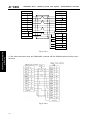
PLC → Address of Machine Tool Side (Y)
The Y address of the GSK218MC PLC composes of two types:
1. The Y address is assorted with the three I/O input terminals, namely, XS43, XS44 and
XS45.
2. The Y address is assorted with the indicator on the MDI panel of the system.
Volume I Programming
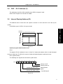
3.2.1
Y Address on I/O Output Port
The addresses (48 addresses) are defined as INT8U from Y0 to Y5, which are distributed on
the three I/O input terminals, for example, XS43, XS44 and XS45.
Users can define the signal significance of the Y address of the I/O ports based upon the actual
cases, which can be connected the machine tool and compiled the corresponding ladder diagram.
Refer to the appendix one (GSK218MC CNC system PLC I/O address) and the configuration and
definition of the internal software components for the initial definition of the input address.
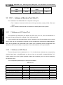
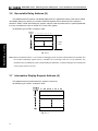
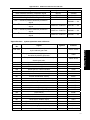
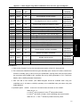
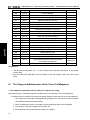
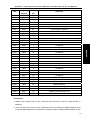
3.2.2
Y Address on MDI Panel
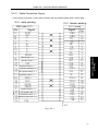
There are 8 types from the addresses Y12 ~ Y19 of which these addresses are corresponding
with the button input on the MDI panel one by one. User can not modify its signal definition. PLC
system reports to the CNC system keyboard module after calculating, and it is used for displaying
the indicator signal.
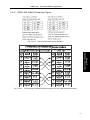
The corresponding relationships of each prompt indicator:
Table 3-2-2-1
16
Keyboard indicator output
PLC add.
Keyboard indicator output
PLC add.
Edit button indicator
Y12.0
Spindle orientation indicator
Y15.7
Auto button indicator
Y12.1
Tool magazine zero return indicator
Y16.0
MDI button indicator
Y12.2
+ Tool magazine indicator
Y16.1
Zero return button indicator
Y12.3
- Tool magazine indicator
Y16.2
Single-step button indicator
Y12.4
Tool magazine infeed indicator
Y16.3
Manual button indicator
Y12.5
Tool magazine retraction indicator
Y16.4
MPG button indicator
Y12.6
Tool magazine releasing/clamping
Y16.5
Chapter Three
Keyboard indicator output
PLC add.
PLC Address
Keyboard indicator output
PLC add.
indicator
(218MC-U1 is RUN indicator)
DNC button indicator
Y12.7
Tool magazine tool-change hand
indicator
(218MC-U1 is READY indicator)
Spindle CCW indicator
Y13.0
USER3 indicator
(218MC-U1 is ALM indicator
Y16.7
Spindle CW indicator
Y13.1
+ the 1st axis button indicator
Y17.0
Spindle stop indicator
st
The 1 axis zero return indicator
nd
The 2
Y13.2
Y13.3
+ the 2
nd
Y16.6
axis button indicator
Y17.1
rd
+ the 3 axis button indicator
Y17.2
th
axis zero return indicator
Y13.4
+ the 4 axis button indicator
Y17.3
The 3 axis zero return indicator
Y13.5
USER1 button indicator
Y17.4
The 4 axis zero return indicator
(218MC);
th
The 4 and the 5th axis zero turn
indicator (218MC-H/-V)
Y13.6
N axis series sequence addition
button indicator
Y17.5
The 5th axis zero return indicator
(218MC)
Y13.7
rd
th
Skip indicator
Y14.0
USER5 button indicator (218MC-U1
is spindle override cancel (100%)
indicator)
Single block indicator
Y14.1
- the 1st axis button indicator
Dry run indicator
Miscellaneous lock indicator
Y14.2
Y14.3
- the 2
nd
Y17.6
Y17.7
Y18.0
axis button indicator
Y18.1
rd
- the 3 axis button indicator
Y18.2
th
Machine locking indicator
Y14.4
- the 4 axis button indicator
Y18.3
Machine illumination indicator
Y14.5
USER2 button indicator
Y18.4
Y14.6
N axis series sequence reduction
button indicator
Y18.5
Cooling indicator
Y14.7
Channel selection button indicator
Y18.6
Chip-removal indicator
Y15.0
JOG button indicator
Y18.7
Feedrate cancel button indicator
Y15.1
Overtravel end button indicator
Y19.0
Rapid switch indicator
Y15.2
Feed dwell button indicator
Y19.1
0.001/F0 button indicator
Y15.3
Cycle start button indicator
Y19.2
0.01/25% button indicator
Y15.4
Tool magazine zero indicator
(218MC integration)
Y19.3
0.1/50% indicator (218MC-U1 is
rapid override 100% indicator)
Y15.5
Optional stop indicator
Y19.4
1/100% button indicator
Y15.6
Program restart indicator
Y19.5
Lubrication indicator
Volume I Programming
USER4 button indicator
17
GSK218MC Series
Machining Center CNC System
PLC & Installation Connection Manual
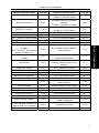
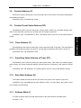
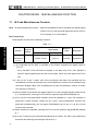
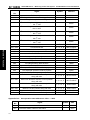
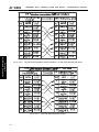
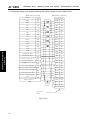
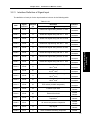
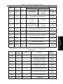
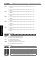
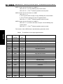
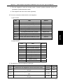
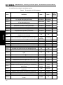
3.3 PLC →CNC Address (G)
The addresses from G0 to G63, its definition type: INT8U, 64 bytes in total.
The operation panel key signal is shown below:
Table 3-3-1
Volume I Programming
Operation panel button signal
PLC add.
Operation panel button signal
PLC add.
Edit method
G20.0
Rapid Fo
G25.0
Auto method
G20.1
Rapid 25%
G25.1
MDI method
G20.2
Rapid 50%
G25.2
Zero return method
G20.3
Rapid 100%
G25.3
Single step method
G20.4
Incremental step length 0.001
G26.0
Manual method
G20.5
Incremental step length 0.01
G26.1
MPG method
G20.6
Incremental step length 0.1
G26.2
DNC method
G20.7
Incremental step length 1
G26.3
SKIP
G21.0
MPG one block to shift 0.001
G26.4
Single block
G21.1
MPG one block to shift 0.01
G26.5
Dry run
G21.2
MPG one block to shift 0.1
G26.6
Miscellaneous lock
Machine lock
Optional stop
Program restart
Spindle CCW (Positive)
Spindle stop
G21.3
G21.4
G21.5
G21.6
G22.0
G22.1
st
G27.0
nd
G27.1
rd
G27.2
th
G27.3
st
G28.0
nd
G28.1
rd
Manual feed axis +1
Manual feed axis +2
Manual feed axis +3
Manual feed axis +4
Manual feed axis -1
Manual feed axis -2
Spindle CW (Negative)
G22.2
Manual feed axis -3
G28.2
Spindle override cancel
(218MC)
G22.4
Manual feed axis –Nth
G28.3
Spindle JOG
G22.6
Spindle orientation
G29.0
Channel selection signal
G22.7
Tool magazine zero return
G29.1
Lubrication
G23.0
Tool clamping/releasing
G29.2
Cooling
G23.1
+ tool magazine
G29.3
Chip-removal
G23.2
- tool magazine
G29.4
Cycle start
G23.6
Tool magazine pivoting
G29.5
Feed hold
G23.7
tool magazine retraction
G29.6
Feedrate cancel
(218MC)
G24.1
Tool-change hand
G29.7
Rapid switch
G24.7
Overtravel releasing
G30.0
The signal of G63 bytes are used inside the system, the G63.0, G63.1 and G63.2 are the
answer signal inside the system separately performed by M, S and T.
18
Chapter Three
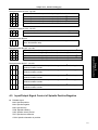
3.4
PLC Address
CNC →PLC Address (F)
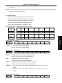
The addresses from F0 to F63 are defined as: INT8U, 64 bytes in total.
Refer to the Chapter Two Function for details.
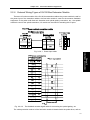
3.5
Internal Replay Address (R)
The address area is reset when the system is turned on. R510 and R511 are used by the
system.
Its definition type is: INT8U, 512 bytes in total.
6
7
5 4
3
2
Volume I Programming
Address
number
1 0
R0
R511
Fig. 3-5-1
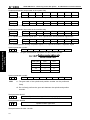
System program administration area
R510
The signal of R510.0 address is set to 1 when PLC starts and restarts, which is used the signal
set by the initial user. The R510.0 is reset to 0 after the ladder diagram is performed once.
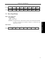
R511 (System timer)
The following four signals can be used for system timer:
7
6
5
4
3
2
1
0
R511
Always cut off
Always power on
(104ms ON, 96ms OFF)
(504ms ON, 496ms OFF)
200ms period
signal
1s period signal
Fig. 3-5-2
19
GSK218MC Series
3.6
Machining Center CNC System
PLC & Installation Connection Manual
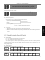
Nonvolatile Relay Address (K)
This address area is used for nonvolatile replay and PLC parameter setting. This area is called
nonvolatile relay area, namely, the content inside the register will not lose even if the system is
turned off. K000~~K005 are used by the system, which is used to protect the PLC system parameter,
it is very convenient for user to control PLC in the CNC system.
Its definition type: INT8U, 64 bytes in total.
Address
number
7
6
5 4 3 2 1 0
K0
K1
Volume I Programming
K relay
area
K63
Fig. 3-6-1
Note: When PLC address K005.2 =1, PLC enters the debugging mode. All of the external alarms are cancelled, and
the machine interlocking signals are then cancelled, the tool-change code can not be performed. The
parameter can be modified only when comprehending the parameter, so that the damage in the machine tool
or injury of the person may occur.
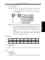
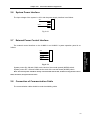
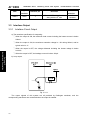
3.7
Information Display Request Address (A)
This address area is cleared when the system is turned on.
Its definition type: INT8U, 32 bytes in total.
Fig. 3-7-1
20
Chapter Three
3.8
PLC Address
Counter Address (C)
This area is used for placing the current counting value of the counter. The data is cleared after
the system is turned off.
Its definition type: 128 addresses in total.
3.9
Counter Preset Value Address (DC)
3.10
Timer Address (T)
This address area is used for storing the current numerical value of the timer. The data initial is
presetting value after the system is power off. Current data is presetting value when it is set to 0.
Its definition type: 128 addresses in total.
3.11
Presetting Value Address of Timer (DT)
This address area is used for placing the timer preset value. This area is nonvolatile register
area, namely, the content inside the register will not lose even if the power of the system is turned
off.
Its definition type: 128 addresses. The setting value of the DT is only read instead of writing.
3.12
Data Table Address (D)
The content inside the memory will not lose even if the power of the system is turned off.
Its definition type: 256 addresses in total. Wherein, D240~247 are used by the system, users
can not define by themselves.
3.13
Address Mark (L)
It is used to specify signs both skip object and the LBL code marks in the JMPB code.
Its range: 0~99
21
Volume I Programming
This address area is used for storing the counter preset, which is a nonvolatile storage area,
that is, the memorized content may not loose even the system is power off.
Its definition type: 128 addresses in total. The setting value of the DC is only read instead of
writing.
GSK218MC Series
3.14
Machining Center CNC System
PLC & Installation Connection Manual
Subprogram Number (P)
It is used to specify the called object subprogram number in the CALL code and the subprogram
number in the SP code.
Its range: 0~99
Volume I Programming
22
Chapter Four
CHAPTER FOUR
PLC Basis Code
PLC BASIS CODE
The design of the sequence program begins from compiling ladder diagram. The ladder
diagram consists of relay contact and function code. The logic relationship in the ladder diagram
composes of sequence program. There are two methods of the sequence program input: one uses
the mnemonic symbol language (The system is not temporarily supported the PLC command code
of the RD, AND and OR); the other one is used the relay symbol. The programming can be compiled
using ladder diagram instead of comprehending the PLC code based upon the latter.
Actually, the sequence program inside the system can be converted into corresponding PLC
code even if it is input by the relay symbol.
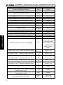
are performed one-digit calculation.
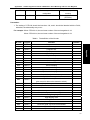
The basis command codes of the GSK218MC series are shown below:
Table 4-1
Code name
Function
RD
Left shift 1-bit of the register’s content, the signal state specified by address is set to
ST0
RD.NOT
Left shift 1-bit of the register’s content, the signal state specified by address is set to
ST0 after its state is set to NOT.
WRT
WRT.NOT
AND
AND.NOT
OR
Output the logic calculation result to the specified address
Output the logic calculation result after NOT to the specified address.
Logic AND
Logic AND after the specified state is set to NOT.
Logic OR
OR.NOT
Logic OR after the specified state is set to NOT.
OR. STK
Right shift 1-bit of the stacked register after ST0 and ST1 logic OR
AND.STK
Right shift 1-bit of the stacked register after ST0 and ST1 logic AND
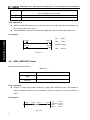
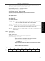
4.1
RD, RD.NOT, WRT, and WRT.NOT Codes
Mnemonic symbol and function
Table 4-1-1
Mnemonic
symbol
RD
Function
Left shift 1-bit of the register’ content, the signal state specified by address is
set to ST0.
23
Volume I Programming
The basis codes are commonly used one when designing the sequence programming, which
GSK218MC Series
Machining Center CNC System
PLC & Installation Connection Manual
RD.NOT
Left shift 1-bit of the register’ content, the signal state specified by address is
set to ST0 after it is set to NOT.
WRT
Output the logic calculation result to the specified address
WRT.NOT
Output the logic calculation result after NOT to the specified address
Code explanation
z WRT and WRT.NOT codes are the coil drive code of the output relay and internal relay, but
the input relay can not be used.
z The parallel WRT command can be used multiply, but it can not output with double coil.
For example
Volume I Programming
X002.1
Y003.7
()
F100.3
G120.0
()
RD
X002.1
WRT
Y003.7
RD.NOT F100.3
WRT
G120.0
Fig. 4-1-1
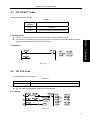
4.2
AND, AND.NOT Codes
Mnemonic symbol and function
Table 4-2-1
Mnemonic symbol
Function
AND
Logic AND
AND.NOT
Logic AND after the specified state is NOT
Code explanation
z Connect 1 contact with series connection by using AND, AND.NOT code. The numbers of
series connection contacts are unconstrained, and this code can be used for dozens of
times.
For example:
X002.1
F100.3
X008.6
Fig. 4-2-1
24
Y003.7
()
RD
X002.1
AND.NOT F100.3
AND
X008.6
WRT
Y003.7
Chapter Four
4.3
PLC Basis Code
OR, OR.NOT Codes
Mnemonic symbol and function
Table 4-3-1
Mnemonic
symbol
Function
OR
Logic OR
OR.NOT
Logic OR after the specified state is NOT
For example:
Fig. 4-3-1
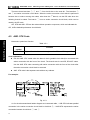
4.4
OR. STK Code
Mnemonic symbol and function
Table 4-4-1
Mnemonic symbol
OR. STK
Function
Right shift 1-bit of the stacked register after ST0 and ST1 logic OR
Code explanation
z OR.STK code is the separate code without any address.
For example:
Fig. 4-4-1
25
Volume I Programming
Code explanation
z Connect 1 contact with series connection using the OR and OR.NOT code.
z OR, OR.NOT is started from the step of this code; it can be connected with series connection
with the abovementioned RD, RD.NOT code step.
GSK218MC Series
Machining Center CNC System
PLC & Installation Connection Manual
There are three branches ①, ② and ③ from the left bus to the node N1. The branches ①
and ② are series connection circuit block. When the series connection circuit block is performed
between bus to node or among the nodes, other than the 1st branch, use the RD code when the
following branch is ended. The branch ③ is not a series connection circuit block, which can be
used by the OR code.
OR. STK and AND. STK are the codes without operation component, which are indicated the
OR , AND relationships between circuit blocks.
4.5
AND. STK Code
Volume I Programming
Mnemonic symbol and function
Table 4-5-1
Mnemonic
symbol
AND.STK
Function
Right shift 1-bit of the stacked register after ST0 and ST1 logic AND
Code explanation
z Use the AND. STK coded when the branch circuit (parallel circuit block) is connected with
series connection with the front of the circuit. The branch start is used RD, RD.NOT codes.
Use the AND. STK code connecting with series connection with the front of the circuit after
the series connection circuit block is executed.
z AND. STK code is the separate code without any address.
For example:
Fig. 4-5-1
As for the abovementioned ladder diagram and command table, ⑴OR.STK indicates parallel
connection in the series connection circuit block in the block ②, ⑵AND.STK expresses the series
connection between circuit block ① and ②.
26
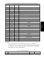
Chapter Five
CHAPTER FIVE
PLC Function Code
PLC FUNCTION CODE
It is hard to compile some machine operations using the basis command codes, but the function
command codes can be simplified it.
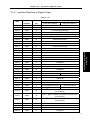
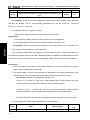
Table 5-1 (218MC series PLC function command code)
Name
Function
Series
No.
Name
Function
1
END1
The 1st level
sequence program
end
19
ROT
Binary rotation control
2
END2
The 2nd level
sequence program
end
20
SFT
Register shift
3
CALL
Call subprogram
21
DIFU
Rising edge detection
4
CALLU
Unconditionally call
the subprogram
22
DIFD
Trailing edge
detection
5
SP
Subprogram
23
COMP
Binary number
comparison
6
SPE
End of subprogram
24
COIN
Consistency
comparison
7
SET
Setting
25
MOVN
Data transfer
8
RST
Resetting
26
MOVB
Transfer of one byte
9
JMPB
Sign skip
27
MOVW
Transfer of two bytes
10
LBL
Sign
28
XMOV
Binary indexed data
transfer
11
TMR
Timer
29
DSCH
Binary data search
12
TMRB
Regular timer
30
ADD
Binary addition
13
TMRC
Timer
31
SUB
Binary subtraction
14
CTR
Binary counter
32
ANDF
Logic AND
15
DEC
Binary decode
33
ORF
Logic OR
16
COD
Binary code
conversion
34
NOT
Logic NOT
17
COM
Control of the
concentric line
35
EOR
Exclusive OR/ XOR
18
COME
End of the concentric
line control
Volume I Programming
Series
No.
27
GSK218MC Series
5.1
Machining Center CNC System
PLC & Installation Connection Manual
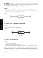
END1 (The 1st Level Sequence Program End)
Function:
This function can be specified once in sequence program at the end of the 1st level program, or
it can be performed at the beginning of the 2nd level program when the 1st level program does not
execute. The first program can be compiled up to 500 steps.
Format:
END1
Fig. 5-1-1
Volume I Programming
5.2
END2 (The 2nd Sequence Program End)
Function:
It specifies at the end of the 2nd level program.
Format:
END2
Fig. 5-2-1
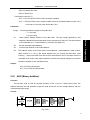
5.3
CALL (Call Subprogram)
Function:
Call one specified subprogram
It owns the following characters and limitations:
Subprogram can be nested and called other subprograms up to 18 layers, as for the endless
repetition caused by the closure call, the system may alarm. The system allows that the maximum
subprogram call number is 100 for controlling the performance data value. The subprogram call can
not be performed at the 1st level program. The code or network wrote between END2 AND SP, or
after SPE, or before SP, the system can not be performed, and then alarms.
Format:
28
Chapter Five
ACT
CALL
PLC Function Code
Subprogram
number
Fig. 5-3-1
Control condition:
ACT=0, Perform next code followed with CALL.
ACT=1, call subprogram of the specified subprogram number
Parameter:
Subprogram number: Specify the called subprogram number. The subprogram number is
5.4
Volume I Programming
indicated at 0~99.
CALLU (Unconditionally Call Subprogram)
Function:
Unconditionally call one specified subprogram
It owns the following characters and limitations:
Subprogram can be nested and called other subprograms up to 18 layers, as for the endless
repetition caused by the closure call, the system may alarm. The system allows that the maximum
subprogram call number is 100 for controlling the performance data value. The subprogram call can
not be performed at the 1st level program. The code or network wrote between END2 AND SP, or
after SPE, or before SP, the system can not be performed, and then alarms.
Format:
CALLU
Subprogram
number
Fig. 5-4-1
Parameter:
Subprogram serial number: Specify the called subprogram number, and its range is 0~99.
29
GSK218MC Series
5.5
Machining Center CNC System
PLC & Installation Connection Manual
SP (Subprogram)
Function:
SP is used to generate a subprogram. The subprogram number is regarded as its name. The
range of the subprogram is specified by the SP code and the after-mentioned SPE code together.
Notice:
1. The subprogram should be compiled followed END2.
2. Another subprogram can not be set inside one subprogram.
Format:
Subprogram
number
SP
Volume I Programming
Fig. 5-5-1
Parameter:
Subprogram number: specify a called subprogram mark number, its range is 0~99.
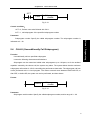
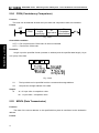
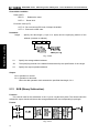
5.6
SPE (End of Subprogram)
Function:
* Use SPE and SP together to specify the range of subprogram.
* The control will return to the main program of the called subprogram when this function
code is performed.
* The subprogram should be compiled after END2.
Figure format
SPE
Fig. 5-6-1
For example
30
Chapter Five
CALL
PLC Function Code
P33
END2
SP
P33
SPE
Fig. 5-6-2
Volume I Programming
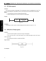
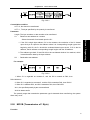
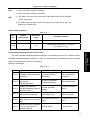
5.7
SET (Replacement/Setting)
Function:
Set 1 in the specified address.
Format:
ACT
SET
Add.b (Address)
Fig. 5-7-1
Controllable condition:
ACT=0, the state of the add.b remains invariable.
ACT=1, the add.b is set to 1.
Parameter:
Add.b: setting component address bit can be treated as the output coil, Add = Y, G, R, K and A.
5.8
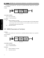
RST (Resetting)
Function:
Set 0 on the specifying place.
Format:
31
GSK218MC Series
Machining Center CNC System
PLC & Installation Connection Manual
Fig. 5-8-1
Controllable condition:
ACT=0, the state of the add.b remains invariable.
ACT=1, add.b is set to 0.
Parameter:
Add.b: resetting component address can be treated as output coil, Add = Y, G, R, K and A.
Volume I Programming
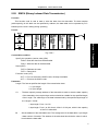
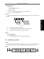
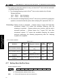
5.9
JMPB (Mark Number Skip)
Function:
JMPB immediately transfers the control to program following with mark number in the ladder
diagram programming.
The characters and limitations are shown below:
* Multiple skip codes can be shared with the same mark number.
* The skip can not be performed each other between the 1st and the 2nd level programs.
* The skip can not be performed among the subprograms.
* Rebound is allowable, but users should hold the endless cycle which may be caused by
it.
* The skip can not be performed between main program and subprogram.
Format:
ACT
JMPB
Destination
mark number
Fig. 5-9-1
Controllable condition:
ACT=0, Do not skip, perform the next code followed JMPB.
ACT=1, Perform the next code after the mark number when the skip jumps to the specified
mark number.
Parameter
Lx: Specify a skip object mark number. Any value (from 0 to 99) can be specified.
32
Chapter Five
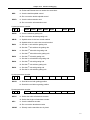
5.10
PLC Function Code
LBL (Mark Number)
Function:
Specify one mark number in the ladder diagram, namely, it is a specified skip destination for
JMPB.
It is very important to notice that one mark number with xx only can be specified once using LBL.
It may alarm if it uses repeatedly.
Format:
Mark number
LBL
Volume I Programming
Fig. 5-10-1
Parameter:
xx: Specify a skip object mark number, its range is 0~99.
For example:
JMPB
33
LBL
33
JMPB
33
Fig. 5-10-2
5.11
TMR (Timer)
Function:
Delay conducting timer.
Format:
ACT
TMR
TIMER (Timer
number)
(W)
Fig. 5-11-1
33
GSK218MC Series
Machining Center CNC System
PLC & Installation Connection Manual
Controllable condition:
ACT=0, close the timer.
ACT=1, start the timer.
The concrete operation is as follows:
ACT
W
TIMER= Setting time
Fig. 5-11-2
Parameter:
Volume I Programming
TIMER : The timer number indicates by xxx (it expresses by numbers from 0 to 127).
Output:
W
:
Output coil. W=1 when it reaches to the resetting value, W=0 means it does not reach
to it.
Note: TIMER performs once each 8ms, its setting unit is ms, and 8ms is the performance radix, complete 8ms if it is
insufficient. For example: the setting is 54ms, 54=6*8+6, complete 2ms, the actual performance is 56ms. The
time of the timer is set in the [TMR] of the [PLCPAR] under the program-controlled interface. The sequence
number of the timer may be detected its range by the system directly. The alarm may occur when the
sequence number repeats or exceeds its range.
5.12
TMRB (Fixed Timer)
Function:
Delay conducting timer
Format:
ACT
TMRB
Timer
Timer Presetting
(W)
time
accuracy number
Fig. 5-12-1
Controllable condition:
ACT=0, Close the timer
ACT=1, Start the timer
The concrete operation is as follows:
34
Chapter Five
PLC Function Code
ACT
W
TIMER = Setting time
Fig. 5-12-2
Parameter:
TIMER: Fix the timer number, it is indicates by xxx, xxx is numbers from 0 to 127.
Table 5-12-1
(Timer accuracy)
Setting No.
Timer range setting
Error range
0
1
Scan period from 0 to the 1st level program
1s
10s
1min
1ms
2
3
4
5
From 8ms to 524.280s
From 48ms to
31.456min
From 1s to 546 min
From 10s to 182 h
From 1min to 65535min
From 1ms to 65.4s
Scan period from 0 to the 1st level program
Scan period from 0 to the 1st level program
Scan period from 0 to the 1st level program
From 0 to 1s
Scan period from 0 to the 1st level program
Presetting time
The time setting of the fixed timer, its numerical range is: 0~65535.
Output
W
:
Coil output. W=1, it reaches to the presetting. W=0, it does not reach.
Note: As for the sequence of the timer, the system may check its range automatically, if the repeated sequence or
out of the range, the system may alarm. The presetting time in timer is solidified in the ROM along with the
ladder diagram, so, the time of the timer only can be changed by modifying the ladder diagram file.
5.13
TMRC (TIMER)
Function
Delay conducting timer
Format
ACT
TMRC
Timer
accuracy
Timer
number
(W)
Fig. 5-13-1
Controllable condition
ACT=0, Close the timer
35
Volume I Programming
Timer
accuracy
8ms
48ms
GSK218MC Series
Machining Center CNC System
PLC & Installation Connection Manual
ACT=1, Start the timer
The concrete operation is as follows:
ACT
W
T IM E R =S etting tim e
Fig. 5-13-2
Parameter
TIMER: The timer number indicates by xxx (xxx expresses by numbers from 0 to 127).
Volume I Programming
Table 5-12-1 (Timer accuracy)
Timer
precision
8ms
48ms
Setting
No.
0
1
Setting time range
Error range
Scan period from 0 to the 1st level program
2
From 8ms to 524.280s
From 48ms to 31.456
min
From 1s to 546 min
1s
10s
1min
1ms
3
4
5
From 10s to 182 h
From 1min to 65535min
From 1ms to 65.4s
Scan period from 0 to the 1st level program
Scan period from 0 to the 1st level program
Scan period from 0 to the 1st level program
From 0 to 1s
Scan period from 0 to the 1st level program
Output:
W
:
Output coil. W=1, it reaches to the presetting, W=0, it does not reach to it.
Note: The time of the timer is set in the [TMR] in the [PLCPAR] controlling by the program control surface. TMRC and
TMR timers are shared with a same address, so, the TMRC and TMR timers can not be repeatedly used. The
system may automatically check the range of the timer sequence. It may alarm when the sequence number is
repeated or exceeded its range.
5.14
CTR (Binary Counter)
Function:
The data in the counter are binary system, which have the following functions based upon the
applications.
1) Presetting counter
If the count reaches to the output signal of presetting value, preset the numerical value.
2) Ring-counter
36
Chapter Five
PLC Function Code
When the counter reaches to the presetting value, it inputs the count signal and resets the initial
value and performs the count again.
3) Addition and subtraction counter
This is treated as the forward-backward counter, which can be used both addition and
subtraction.
4) The selection of the initial value
The initial value can be regarded as 0 or 1.
Format:
Volume I Programming
Fig. 5-14-1
Controllable condition:
Specify initial value (CN0):
CN0=0, counter begins with 0.
CN0=1, counter begins with 1.
Specify rising or descending counter (UPDOWN):
UPDONW=1, subtraction counter
UPDOWN=0, addition counter
Reset (RST):
RST=0, Remove the reset
RST=1, reset: W resets to 0, and the counter value reset to initial value. The RST is set
to 1, as long as the reset is required.
Counting signal (ACT):
ACT=1: Count performs when ACT is at the rising edge.
ACT=0: Counter does not operate, W holds unchangeable.
Parameter:
COUNTER: Specify the number of the counter, which is indicated by xxx (xxx is No. 0 to
No.127).
Output:
W
:
Coil output, W=1, it reaches to the presetting value.
Note 1: The system may automatically check the sequence number range of the timer, it may alarm if the sequence
37
GSK218MC Series
Machining Center CNC System
PLC & Installation Connection Manual
is repeated or exceeded its range.
Note 2: The current value of the timer may automatically clear, after the ladder diagram is converted and
downloaded.
Reset the counter by the pulse signal before counting for ensuring the reliable of the counter.
5.15
DEC (Binary Decoding)
Function:
DEC can be decoded for the binary system code data, one of the consecutive data of the
specified 8-bit (1 type) or 16-bit (2 types) is same as the code data. The corresponding output data
Volume I Programming
bit is 1; the output data is 0 without any same number.
This code is used for the data decode of M or T function.
Format:
Fig. 5-15-1
Controllable condition:
ACT=0: Reset all of the output bits.
ACT=1: Perform the data decode; the treated result is set at the output data address.
Parameter:
Length: Set the dimension of the code data at the 1st bit data of the parameter.
0001: The code data is binary system code data of one byte.
0002: The code data is binary system code data of two bytes.
S1: Code data address. Specify an address of the storage code data.
S2: Decoding specifying No. Specify the 1st bit with the consecutive number of the 8-bit to be
decoded (1 byte) or 16-bit (two bytes).
S3: Decode result address. Specify an address output the decoding result. The register area
must be output with one byte or two bytes areas.
For example:
ACT
DEC
1
F10
Fig. 5-15-2
38
8
R4
Chapter Five
PLC Function Code
When ACT=1, F10=8, R4=0000,0001;
When ACT=1, F10=9, R4=0000,0010;
………………………….
When ACT=1,F10=15, R4=1000,0000;
5.16
COD (Binary System Code Conversion)
Function:
COD code may automatically produce a corresponding table under its function block when it
inputs the data capacity, which is used for inputting the conversion table data for the user. 10 grids of
capacity data does not change, and then the address of the table number may not display.
Format:
Fig. 5-16-1
Table 5-16-2
0
XXX
10
………
S1
S2
S1
S2
1
YYY
11
………
2
AAA
12
………
………
………
………
………
9
………
N-1
UUU
Controllable condition:
Reset (RST):
RST=0, Do not reset.
RST=1, It will output W resetting incorrectly
Working code (ACT):
ACT=0: Do not perform the COD.
ACT=1: Perform the COD. The value of the “conversion input data address (S1)” is
regarded as the table number of the conversion table, the corresponding
conversion data of the table number is taken out from conversion table to
output the “output address to the conversion data (S2)”.
39
Volume I Programming
each row in this table, it calculates based upon the quotient +1 if it can not be exactly divided, but the
GSK218MC Series
Machining Center CNC System
PLC & Installation Connection Manual
Fig. 5-16-2
Volume I Programming
Parameter:
Length1: Specify the byte number of the binary system data of the conversion data in the
conversion table.
1: Binary system of 1 byte.
2: Binary system of 2 bytes.
Up to 512 bytes.
Length2: The capacity of the conversion table data. Each conversion table capacity can
not more than 100, it is 100 bytes when 1 type format is specified; it is 100 bits
when 2 bytes format are specified. The total capacity of the entire COD codes
conversion table should be less than 512 bytes.
S1: The data in the conversion table can be taken out by the specifying table number,
and the address of the specifying table number is regarded as the input address of
the conversion data. This address should be supplied a register with one byte.
S2: The output address of the conversion data. Specify the byte numbers of the register
in the form specification beginning with the address.
Output:
If the abnormal occurs during the COD code performs. W=1, it indicates that the error issues.
Note: The capacity of the conversion data table is up to 100 bytes (bits), this table is compiled between the
parameter conversion data output address and error output (W).
5.17
COM (Concentric Line Control)
Function
COM specifies the control until the coil working within the public end code COME range. The
system may alarm if the public end code does not specified.
Format:
40
Chapter Five
PLC Function Code
Fig. 5-17-1
Controllable condition:
When ACT=0, the coil within the specified range is cut off without any condition (W=0).
Note 1: Do not specify another COM code within the range of one COM code.
Note 2: When the ACT = 0 of the COM, the coil within the specified range WRT NOT is set to 1 at any time (WRT
NOT = 1).
Note 3: The function codes, such as JMPB, END1, END2, CALL, CALLU, LBL, SP, SPE, COM and COME, can not
be used between COM and COME, otherwise the system may alarm.
5.18
COME (Concentric Line Control End)
Function:
This code is specified the controllable range of the concentric control line code (COM), which
can not be used separately; it must be used with COM together.
Format
COME
Fig. 5-18-1
5.19
ROT (Binary Rotation Control)
Function:
It is used for the revolving control, such as the tool post and rotation worktable. The code is
with some functions, refer to the following:
1. Select the revolving direction with the short path.
41
Volume I Programming
When ACT=1, it is same as the end of COM code.
GSK218MC Series
Machining Center CNC System
PLC & Installation Connection Manual
2. Count the steps from the current position to the objective one; or count the steps from the
previous position of the current one to the previous position of the objective one.
3. Count the position number at the objective previous position or the steps at the objective
previous position.
Format:
CNO
S4
Calculation result
output address
Volume I Programming
S3
Objective position
address
POS
S2
Current position
address
DIR
S1
Rotary table
position address
ROT
(W)
INC
ACT
Fig. 5-19-1
Controllable condition:
Specify the initial number of the rotary table (CN0):
CNO=0, counter begins with 0.
CNO=1, counter begins with 1.
Check whether the short path can be selected the rotation direction (DIR):
DIR=0, Do not select; the selection direction is only positive.
DIR=1, Selection; the selection direction can be divided into positive or negative.
Specify the operation condition (POS):
POS=0, counting objective position
POS=1 the previous position of the counting object
Specify the position numbers and steps (INC):
INC=0, counting position number. Specify INC=0 and POS=1 if the previous position of
the objective one is to be calculated.
INC=1, counting steps. Perform the code (ACT) when the code INC=1 and POS=0, if
the distance between the current position and the objective one is to be
calculated.
Performance code (ACT):
ACT= 0, do not perform the ROT code. W is without change.
ACT=1, perform the ROT code. Generally, set the ACT=0, if the operation result is to
be required, and then set the ACT=1.
Parameter:
S1 : Provide the rotary position number.
S2 : Provide the address storing the current position.
S3 : Specify the address (or code value) storing the objective position. For example,
store the address of the T code outputting from the CNC.
S4 : The calculation outputs to address, compute the steps to be rotated of the rotary,
42
Chapter Five
PLC Function Code
which reaches to the objective position or the previous position. Always check
whether the ACT is 1 when using the calculation result.
Output:
W
:
Rotation direction output. It outputs to the W by the short-circuit rotation direction,
its direction is positive (FOR) when W=0; it is the negative direction (REV) when
W=1. The definitions of the FOR and REV are shown below, the increase direction
of the position number of the revolving table is positive (FOR); it is the negative
direction in the decrease state. The address of W can be selected freely, however,
if the W results should be used, always check the condition of the ACT=1.
For example: One revolving table is shown below:
Volume I Programming
Fig. 5-19-2
Fig. 5-19-3
Perform the short path rotation, and calculate the position No. of the previous one for the
objection position.
Current position No. S2=1, revolving index position No. S1=12, CNO=1, DIR=1, POS=1 and
INC=0
Wherein:
S3=10, S4=11, W=1, when the objective position is A in the ACT = 1.
S3=8, S4=9, W=1, when the objective position is B in the ACT = 1.
43
GSK218MC Series
Machining Center CNC System
PLC & Installation Connection Manual
S3=5, S4=4 and W=0, when the objective position is C in ACT = 1.
S3=3, S4=2 and W=0 when the objective position is D in the ACT = 1.
5.20
SFT (Register Displacement/Shifting)
Function:
This code can be shifted 1 byte (8-bit) based upon the digits specifying by the code parameter
each time. The “1” that overflows from cycle shifting will be added from the negative direction, for
example, the top bit “1” is overflown when shifting to left, the lowest bit supplies “1”, vice versa.
Format:
Volume I Programming
Fig. 5-20-1
Controllable condition:
Specify the shifting direction (DIR)
DIR=0, left shift
DIR=1, right shift
State specifying (CONT)
CONT=0, Do not perform the cycle shifting
CONT=1, perform the cycle shifting
Reset (RST)
Reset shifting output data (W=1) is (W=0)
RST=0, W does not reset
RST=1, W resets (W=0)
Execution condition (ACT)
ACT=0, Do not perform the SFT code.
ACT=1, Perform the shifting, set ACT to 0 after the code is performed, if only 1 bit is
moved.
44
Chapter Five
PLC Function Code
Parameter:
S1
: Set the shifting data address, it composes of one storage area by 1 byte.
Length: it is a 4-digit, which is shown in the following figure:
Fig. 5-20-2
L: its range is 0~8
Volume I Programming
A: It is treated as bit-parameter, it is always shifted when ACT =1 during A =0, and it moves
once each period.
ACT is regarded as the pulse signal when A = 1, and when the value turns into 1 from 0, it
moves once.
Output:
W
:
“1” state does not move out when the W = 0 shifting operation is performed.
“1” state moves out when the W = 1 shifting operation is performed.
5.21
DIFU (Rising Edge Detection)
Function:
This code is set the output signal to 1 during the scan period of the input signal rising edge.
Format
ACT
DIFU
L Rising edge
number
(W)
Fig. 5-21-1
Controllable condition:
Input signal: The output signal is set to 1 at the rising edge (01) of the input signal.
Output signal: The output signal keeps to 1 during one scan period of the ladder diagram when
the function code is performed.
Parameter:
L : The range of the rising number is 0~255. The system alarm may occur when another
DIFU code or DIFD code is used the same number in the ladder diagram.
Operation:
45
GSK218MC Series
Machining Center CNC System
PLC & Installation Connection Manual
Fig. 5-21-2
The system may automatically check the range of the series number of the rising edge, as for
the repeated series number or the exceeding range, the system alarm may occur.
Volume I Programming
5.22
DIFD (Descending Edge Detection)
Function:
This code outputs 1 signal of one scan period when inputting the signal descending edge.
Format:
ACT
DIFD
L Descending
edge number
(W)
Fig. 5-22-1
Controllable condition:
Input signal: The output signal is set to 1 at the descending edge (10) of the input signal.
Output signal: The state in the output signal keeps one scan period of the ladder diagram when
this function code is performed.
Parameter:
L : The range of the descending edge number is 0~255. The system alarm may occur when
another DIFU code or DIFD code is used the same number in the ladder diagram.
Operation:
46
Chapter Five
PLC Function Code
Fig. 5-22-2
The system may automatically check the range of the series number of the descending edge,
as for the repeated series number or the exceeding range, the system alarm may occur.
5.23
COMP (Comparison of Binary Number)
Function:
Compare the dimensions of two binary number data. Specify the enough bytes to store the input
data and comparison data in the memory block.
Volume I Programming
Format:
Fig. 5-23-1
Controlled condition:
ACT=0, Do not perform the COMP code. W value is invariable.
ACT=1, Perform the COMP code
Parameter:
Length: Input the specified format (constant or address) and the specified data length (1 byte
or 2 bytes) of the data.
Fig. 5-23-2
S1, S2: The contents both the comparison 1 and comparison 2 can be regarded as constant
and address number.
Address No.: Type R, X, Y, F, G, K, A, D and C
Output:
W =0: Data input > Data comparison
W = 1: Data input ≤ Data comparison
47
GSK218MC Series
5.24
Machining Center CNC System
PLC & Installation Connection Manual
COIN (Consistency Comparison)
Function:
This code can be detected whether the input value and comparison value are consistent.
Format:
ACT
COIN
Length
format
specifying
S2
S1
Comparison
Input value value address
(W)
Fig. 5-24-1
Controllable condition:
ACT=0, Do not perform the COIN code. W value is invariable.
Volume I Programming
ACT=1, Perform the COIN code.
Parameter:
Length: Input the specified format (constant or address) and the specified data length (1 byte
or 2 bytes) of the data.
Fig. 5-24-2
S1
:
The input data can be specified both the constant and storage address.
S2
:
Compare the storage address of the data.
Output:
W
:
W = 0: input value ≠ comparison value
W = 1: input value = comparison value
5.25
MOVN (Data Transmission)
Function:
The data of the source address or the specified binary data is transferred to the destination
address.
Format:
48
Chapter Five
PLC Function Code
Fig. 5-25-1
Controllable condition:
ACT=0, No data to be transferred
ACT=1, The byte specified by the quantity is transferred.
Parameter:
Length: The byte numbers or data number to be transferred.
S1
:
Resource start address or constant.
1. If the S2 is single byte address, S1 is the constant, the resolution of the S1 based
upon the byte is copied to the address where it is corresponding Length type at the
beginning with S2; the S1 should be evaluated based upon the bit, if S2 is the bit
address; the bit address corresponding Length begins with the S2 address.
2. The address type both S1 and S2 will not be considered whether it is matched, which
is transferred the data by the byte address.
S2
:
Destination start address.
For example:
Fig. 5-25-2
1. When S1 is regarded as constant 5, and the S2 is treated as R60, then
R60=00000101
2. When S1 is regarded as constant 5, and the S2 is treated as D60, then D60=5.
3. When S1 is address D50, and S2 is treated as D60, then D60=D50.
W=1, the specified quantity bytes are transferred.
W=0 No data transfer
The quantity range that exceeds the parameter type is detected when transferring, the system
alarm may occur.
5.26
MOVB (Transmission of 1 Byte)
Function:
49
Volume I Programming
Select the transfer form based upon the S1:
GSK218MC Series
Machining Center CNC System
PLC & Installation Connection Manual
The MOVB code transfers the 1 byte data to a specified destination address from a specified
resource address.
Format:
Fig. 5-26-1
Controllable condition:
ACT=0, No data transfers.
ACT=1, 1 byte is transferred.
Volume I Programming
Parameter:
S1
:
Resource address or constant
If the S2 is single byte address, the S1 should be copied to the S2 address based
upon the byte value; if S2 is bit address, the S1 should be copied to the S2 lower
byte address based upon the byte value.
S2
5.27
:
Destination address
MOVW (Transmission of Two Bytes)
Function:
MOVW code transfers the 2 bytes data to a specified destination address from a specified
resource address.
Format:
Fig. 5-27-1
Controllable condition:
ACT=0, No data transfers.
ACT=1, 1 byte is transferred.
Parameter:
50
S1
:
Resource address or constant
S2
:
Destination address
Chapter Five
5.28
PLC Function Code
XMOV (Binary Indexed Data Transmission)
Function:
This function code is used to read or write the data from the data table. The data number
(table-capacity) in this table can be specified by address; the data table can be operated by PLC
based upon the user’s setting during operating.
Format:
Volume I Programming
Fig. 5-28-1
Controllable condition:
Specify the operation (read or write) (RW)
RW=0: Read the data from the data table.
RW=1: Write the data to the data table.
Reset (RST)
RST=0: Release the reset
RST=1: Reset W=0.
Execution code (ACT)
ACT=0: Do not execute the XMOV code, W keeps invariable.
ACT=1: Execute the XMOV code.
Parameter:
Length: The format specifies the length of the transmission data.
1: 1 byte length.
2: 2 bytes length.
S1
:
The data capacity storage address of the data table is used to store the data capacity
of the data table; the occupied byte number should be suitable for the specified length
of the Length. The valid range of the data is determined by the specified byte length of
the Length 1 format.
1 byte length: From 1 to 512.
2 byte length: From 1 to 256, that is, 256×2=512 bytes, which is the capacity
of the PLC data table.
S2
: Set the address of the data table head. The storage area of the data table = byte length
× data number of its table. The address of the table head should be the value in which
is set inside the data table.
51
GSK218MC Series
S3
Machining Center CNC System
PLC & Installation Connection Manual
: Input/output address. Set and place the address from the reading when the data is read.
Set and place the address from writing when the data is write. Its byte numbers should
be suitable from the setting of the Length format. This address is defined as D register.
S4
: Storage address of the table number. It is used to store the table number to be read or
write. It occupied bytes should be suitable for the specifying in the Length. If the setting
of the table number is more than the data registered in the S1, it outputs W=1 in a
wrong way.
Output:
When the value in the table number exceeds the S1, W=1, the read or write of the data table
does not perform.
W=0, Without error
Volume I Programming
W=1, Error
5.29
DSCH (Binary Data Index)
Function:
This function code can be use for indexing the binary data in the data table. The data number
(table capacity) in the data table can be specified by address. In this case, the table capacity still can
be changed even if the program is written into ROM.
Format:
Fig. 5-29-1
Controllable condition:
Detection repetition (REP)
REP=0: Perform DSCH code, start to search it from the first address of the data table, it
will not consider the destination data may generate repeatedly; it may stop the
search outputting its address when detecting the destination data at the first
time. W=1, if the indexed data does not find.
REP=1: Perform DSCH code. If the indexed data does not find or it has two or above
data, W=1.
Reset (RST)
52
Chapter Five
PLC Function Code
RST=0, Release the reset.
RST=0: Reset W=0.
Performance code (ACT)
ACT=0: Do not perform DSCH code, W keeps invariable.
ACT=1: Perform DSCH code. Output its table number if the indexed data is found; if it is
not found or it has two more above data, W=1.
Parameter:
Length :
Format specifies the length of the index data.
1: 1 byte long
2: 2 bytes long
S1
:
Data number storage address of the data table. The byte length specified by this
of the data table is n+1 (table head is 0, the end of the table is n).
S2
: Set the data table head address.
S3 : Set the input address of the index address.
S4 : The address output of the index result. Actual address = head address + table number,
table number is 0~(S1-1), the actual address can not exceed the data table. After
indexing:
output its number from the list if the index data is found. The table number is
outputted to the index result output address of which the required storage byte number
should be suitable for the specified format.
Output:
W=0, Find the indexed data.
W=1, Do not find the indexed data.
5.30
ADD (Binary Addition)
Function:
This function code is used for the add operation of the 1 byte or 2 bytes binary data. The
addend data and the add operation output the data should be set the storage address with the
corresponding byte length.
Format:
Fig. 5-30-1
53
Volume I Programming
address is distributed the storage area for the requirement of the byte. The data number
GSK218MC Series
Machining Center CNC System
PLC & Installation Connection Manual
Controllable condition:
Reset (RST):
RST=0
RST=1 :
: Release the reset.
Reset W=0.
Execution code (ACT)
ACT=0: Do not execute ADD code, W keeps invariable.
ACT=1: Execute the ADD code.
Parameter:
Length
: Specify the data length (1 byte or 2 bytes) and the specifying method of the
addend (constant or address).
Volume I Programming
Fig. 5-30-2
S1
: Specify the storage addend address.
S2 : The specifying method of the addend is determined by the specification of the Length.
S3
: Specify the output operation address.
Output:
W=0: Operation is normal.
W=1: Operation is abnormal.
When the add operation result exceeds the specified data length, W=1.
5.31
SUB (Binary Subtraction)
Function:
This code is used for the subtraction of the 1 byte or 2 bytes binary data. The minuend and the
subtraction output data should be set the storage address with the corresponding byte length.
Format:
Fig. 5-31-1
54
Chapter Five
PLC Function Code
Controllable condition:
Reset (RST):
RST=0: Release the resetting.
RST=1: Reset W=0.
Execution code (ACT):
ACT=0:
ACT=1:
Do not execute the SUB code, W keeps invariable.
Execute the SUB code.
Parameter:
Length: Data length specified (1 or 2 bytes) and the addend specifying method (constant or
address).
Volume I Programming
Fig. 5-31-2
S1 : Specify and store the minuend address.
S2 : The specifying method of the subtractor is determined by Length.
S3 : Specify and output the address of the operation result.
Output:
W=0: Normal operation.
W=1: Abnormal operation.
The subtraction result exceeds the specified data length, W=1.
5.32
ANDF (Bit-by-bit AND)
Function
This code is performed the AND with a constant (or the content from the address B) from the
content of the address A (or the one from the address B), and its result is stored to address C.
Format:
Fig. 5-32-1
55
GSK218MC Series
Machining Center CNC System
PLC & Installation Connection Manual
Controllable condition:
ACT=0: Do not execute ANDF code.
ACT=1: Execute the ANDF code.
Parameter:
Length
: Specify the data length (1 byte or 2 bytes), input the data format (constant or
address).
Volume I Programming
Fig. 5-32-2
S1: Specify the input data that will to be performed by AND. The address is then begins and the
data length is consistent with the Length.
S2: The input data is performed with the one of the AND. When the format specifying is
selected the address, the address is then started, and the data length is consistent with the
length.
S3: It is used for storing the address of ANDF operational result. The result from the ANDF is
stored from this address, and the data length is consistent with the one of the Length.
For example: When the address A and B have the following data, which are shown below:
Address A
Address B
1
0
1
1
1
0
0
1
0
0
0
1
1
0
1
1
0
0
0
1
The operational result of the ANDF is shown below:
Address C
5.33
0
1
0
0
ORF (Bit-by-bit OR)
Function:
This code is performed the OR with a constant (or the content from the address B) from the
content of the address A, and its result is stored to address C.
Format:
56
Chapter Five
PLC Function Code
Fig. 5-33-1
Controllable condition:
ACT=0: Do not execute the ORF code.
ACT=1: Execute the ORF code.
Parameter:
Length
: Specify the data length (1 byte or 2 bytes), input the data format (constant or
address).
S1
: Specify the input data that will to be performed by NOT. The address is then begins
and the data length is consistent with the length.
S2
:
The input data is performed with the one of the OR. When the format specifying is the
address specification, and therefore, the address starts, and the data length is
consistent with the specified Length..
S3
: It is used for storing the address of ORF operational result. The result from the ORF is
stored from this address, and the data length is consistent with the one of the length.
For example: When the address A and B have the following data, which are shown below:
Address A
1
1
1
0
0
0
1
1
Address B
0
1
0
1
0
1
0
1
1
1
1
The operational result of the ORF is shown below:
Address C
5.34
1
1
1
1
0
NOT (Bit-by-bit NOT)
Function: This code is reversed to each content in address A, and store the result to the address B.
Format:
57
Volume I Programming
Fig. 5-33-2
GSK218MC Series
Machining Center CNC System
PLC & Installation Connection Manual
Fig. 5-34-1
Controllable condition:
ACT=0, Do not execute the NOT code.
ACT=1, Execute the NOT code.
Parameter:
Length: Specify the data length (1 byte or 2 bytes)
Volume I Programming
Fig. 5-34-2
S1
:
The input data is reversed bit-by-bit. The address is started and the data length is
consistent with the length.
S2 : It is used for outputting NOT operational result. The result of the NOT operation starts
to store from this address, and the length of the data is consistent with the one of the
length.
For example:
When the address A and B have the following data, which are shown below:
Address A
1
1
1
0
0
0
1
1
1
0
0
The operation result of the NOT is shown below:
Address B
5.35
0
0
0
1
1
EOR (Exclusive OR)
Function:
This code is performed the Exclusive OR with a constant (or the content from the address B)
from the content of the address A, and its result is stored to address C
58
Chapter Five
PLC Function Code
Format:
Fig. 5-35-1
Controllable condition:
ACT=0 : Do not execute the EOR code.
ACT=1: Execute the EOR code.
Parameter:
address).
Fig. 5-35-2
S1
: Specify the input data that will to be performed by Exclusive OR. The address is then
begins and the data length is consistent with the length.
S2
:
The input data is performed with the one of the Exclusive OR. When the format
specifying is selected the address, the address is then started, and the data length is
consistent with the length.
S3
: It is used for storing the address of EOR operational result. The result from the EOR
is stored from this address, and the data length is consistent with the one of the
length
For example: When the address A and B have the following data, which are shown below:
Address A
1
1
1
0
0
0
1
1
Address B
0
1
0
1
0
1
0
1
1
1
0
The operational result of the EOR is shown below
Address C
1
0
1
1
0
59
Volume I Programming
Length : Specify the data length (1 byte or 2 bytes), input the data format (constant or
GSK218MC Series
CHAPTER SIX
Machining Center CNC System
PLC & Installation Connection Manual
COMPILATION LIMIT OF LADDER DIAGRAM
1. The program should with the codes END1 and END2, which are regarded as the end symbol
of the 1st level and 2nd level program, and the END1 should be placed before END2.
2. It is only support the parallel output instead of the multi-level output.
3. The result output address in the overall basis codes, output function codes can not be set as
the following addresses:
1) Counter presetting address DC, timer presetting address DT.
2) The addresses from K0 to K5 are occupied by system, user can not define it.
3) The addresses G63, R510 and R511 are occupied by system, and therefore the user can
not define it.
Volume I Programming
4) X address and F address on the I/O input port.
4. The vertical hovering, the node point does not connect to the following node and the parallel
conducting line is performed the parallel connection to the node network of which the
above-mentioned circumstances will generate the node or network which can not be
performed; and therefore, the system alarm occurs.
5. The start network, that is, it does not connect directly between different vertical lines in the
same row; one of row does not consecutively connect to the vertical line. As for this case, the
system can not be treated, and therefore the alarm occurs.
6. The upper embossment can not be accepted inside the network, that is, the parallel network
generates on several nodes on one certain row, and any row of it can not be connected to this
parallel network. The system alarm may issue.
The following cases are regarded as syntax error, the system alarm may occur.
(W)
(W)
(W)
(W)
(W)
(W)
(W)
Fig. 6.1
60
Chapter Six
Compilation Limit 0f Ladder Diagram
Volume I Programming
61
GSK218MC Series
VOLUME II
Volume II Operation
62
Machining Center CNC System
PLC & Installation Connection Manual
OPERATION EXPLANATION
63
GSK218MC Series
Machining Center CNC System
CHAPTER ONE
1.1
GSK218MC Series
PLC & Installation Connection Manual
PLC INTERFACE DISPLAY
Automatic Operation in PLC ON
PLC operates when the system is turned on: the 1st period may use the R510.0 to conduct a
period of its network cables, the value of the R510.0 is then reset to “0”; the user can not output this
value. The value of the nonvolatile relay is the one of the last output before PLC stops.
Note: The keys inside the < > in the following explanations are panel buttons; the keys inside the 【 】is the soft
button under the screen; 【 】is the interface corresponding with the current soft key;
means that it includes
submenu; all of the PLC operations are performed in the MDI mode, other methods only can be viewed and
searched.
Volume II Operation
1.2
Program-Controlled Interface Display
1.2.1
INFO Interface
1. Enter the page by pressing the <program-controlled> key; enter the INFO interface
pressing the [INFO] soft key, refer to the Fig. 1-2-1-1. Also, it can be set the <program-controlled>
key to shift the screen in the PLC interface by defining the bit parameter No: 26#6=1, and then enter
the INFO interface. This interface offers some relative information of this system, such as the
version number, modification data etc.
Fig. 1-2-1-1
(1) The ladder diagram name in current operation is supplied on the interface. The ladder diagram
64
Chapter One
PLC Interface Display
divides into three types: the only one ladder diagram in operating, the rest of 15 ladder diagrams
other than the operation of the ladder diagram 0—15 and the other ladder diagrams for compiling
and reference (Any two numbers can be identified or named other than 0-15).
(2) The value of the system is set by bit parameter 53#0~#3 when the power is turned on
initialization, which is the composed parameter of binary system; the No. 0 ladder diagram is
used when this value is set to 0; when this value is set to 1~15, the No. 1~15 ladder diagrams
are then used. The ladder diagram file for loading some one number is called operation file (this
operation may cause hazard; it is enabled after restarting when the power is turned off). This
file may be deleted to rebuild if the format is incorrect. So, the user should carefully specify the
file name of the ladder diagram. The overall file names of the ladder diagram must be
“ladderXX.grp” (XX is number), otherwise, the files may not be identified by the system. The file
format is described by the system, the user can not modify it without the system; otherwise, it
(3) M6 is separately called the macro program from O91000 to O91015 when the 0~15 ladder
diagrams are used.
(4) The selection of the ladder diagram. The file name can be specified by moving the cursor or
inputting the “LX”/“LXX” (X/XX is number). The system may detect whether the X”/“XX is the
known file name by pressing the “input” key. If it does not detect, the ladder diagram file should
be set up based upon the file name “ladder0X.grp” or “ladderXX.grp”. The system may
automatically generate two function blocks “END1” and “END2” when the new file is set up, so
that the user can consecutively operate this ladder diagram file (The command table remains
null if it is converted after opening the file). User can copy or cut the ladder diagram from the
normal file (it can not exceeds 100 rows, otherwise, only the previous 100 rows can be
performed) pasting to other file, then copy the function (without modification), and then set up a
new file. For safety’s sake, after the ladder diagram is compiled, the current file may
automatically stored when another file is opened; the ladder diagram syntactic may be detected
before storing of which it may give up if the incorrect syntax is found.
(5) The file header includes the basis information of the file such as the line number and step
number, wherein, the step information occurs as long as it is converted, otherwise, it always
keeps the opening information. User can delete the unopened and unoperated ladder diagram
file; this operation is the irreversible operation, so user should be careful. The system may stop
the renewal of the ladder diagram network after the user open the unoperated ladder diagram,
in order to avoid the misguidance. The operating ladder diagram can only be stored and copied,
so that user can copy this information to others ladder diagram files. It is better to stop the
operation before compiling the current ladder diagram. When the cursor stops at the
background compiling file, user can open the Info information to modify the compiling file
background (including the ladder diagram version number, suitable machine and ladder
65
Volume II Operation
may be deleted or can not be identified.
GSK218MC Series
Machining Center CNC System
PLC & Installation Connection Manual
diagram maintainer) by the “modification” key.
1.2.2
PLCGRA Interface
Enter PLCGRA interface pressing the [
PLCGRA] soft key, it also can be set the
<Program-controlled> key to shift the screen in the PLC interface by defining the bit parameter N0:
26#6=1, and then enter the PLCGRA interface. Refer to the Fig. 1-2-2-1:
Volume II Operation
Fig. 1-2-2-1
The content and operation of the PLCGRA interface:
PLCGRA [ladder01]: Operate the current ladder diagram name.
1/972: It means that the cursor specified line is at the place of the ladder diagram.
Run: Ladder diagram operation state. The operation state of the ladder diagram includes RUN,
STOP and DEBUG.
Figure area: Ladder diagram program
Input: Display the input data. The input data can be enquired pressing the
on the panel.
MEA: The note of cursor positioning node
MDI: Current working method (The ladder diagram can be modified only in the MDI mode).
The searching and positioning can be performed by the page-up, page-down and other
direction keys, the components then can be viewed and modified.
1.2.3
PLCPAR Interface
Enter PLCGRA interface pressing the [
66
PLCGRA] soft key, it also can be set the
Chapter One
PLC Interface Display
<program-controlled> key to shift the screen in the PLC interface be defining the bit parameter N0:
26#6=1, and then enter the PLCGRA interface. Refer to the Fig. 1-2-3-1:
Volume II Operation
Fig. 1-2-3-1
The content and operation of the PLCPAR interface:
RUN: The operation state of the ladder diagram
ADDR: Nonvolatile/keep relay address
Bit0~Bit7: Bit number state of the nonvolatile relay address
1: It means that this address remains the original state (before the power off);
0: It means that the address is rest to default state after the power is turned off.
Input: Display the input data.
MDI: Current working method. (Note: The relative parameters of the PLCPAR can be modified
only in the MID mode.)
The searching and positioning can be performed by the page-up, page-down and other
direction keys, the corresponding address then can be viewed and modified.
1.2.4
PLCDGN Interface
Enter
the
PLCDGN
interface
by
[PLCDGN]
soft-key,
it
also
can
be
set
the
<Program-controlled> key to shift the screen in the PLC interface by defining the bit parameter N0:
26#6=1, and then enter the PLCDGN interface. Refer to the Fig. 1-2-4-1.
67
GSK218MC Series
Machining Center CNC System
PLC & Installation Connection Manual
Volume II Operation
Fig. 1-2-4-1
The content and operation of the PLCDGN interface:
RUN: Operation state of the ladder diagram
ADDR: Address of diagnosis number
Bit0~Bit7: The bit number state of the diagnosis address. 1: with signal breakover; 0: without the
signal breakover.
Input: Display the input data.
MDI: Current working method
The searching and positioning can be performed by the page-up, page-down and other
direction keys, the corresponding diagnosis number then can be viewed and modified.
Generally, only the searching operation can be performed in the interface, the I/O terminal of
the PLC enters signal debugging mode, after only the user gain the limit setting that K0.1 is set to 1,
in this case, user can modify the X and Y signals.
1.2.5
PLCTRAE Interface
PLCTRA interface composes of two sub-interface “Setting” and “Trace”. Enter the PLCTRAE
“Setting” interface by pressing the [ PLCTRAE] soft key under the screen.
Refer to the Fig. 1-2-5-1 for PLCTRACE “Setting” interface:
68
Chapter One
PLC Interface Display
Volume II Operation
Fig. 1-2-5-1
The content and operation of the PLCTRAE “Setting” interface
(1) Mode:
- - Circular cycle: periodic sampling for each time.
- - Signal change: sampling when signal changes.
(2) Resolution:
Input the sampling resolution, the default value is the least resolution (8ms), its range is
(8ms --1000ms).
The input value uses the multiple of the 8ms.
(3) Time limit:
When the sampling mode is set to “periodic cycle”, this parameter then displays. Input the
performance time of the trace. The numerical range of the “periodic cycle” is determined by the value
of the “resolution” or the specified signal address quantity, and its range is displayed at the right side.
(4) Frame limit:
When the sample mode is set to “signal change”, then display this parameter. Input the sampling
quantity, and its range is displayed at the right side.
(5) Stop condition:
- - without: Do not stop tracing.
- - Buffer area full: It stops tracing when the buffer area is full.
- - Signal trigger: It stops tracing by the signal trigger.
Trigger setting: This parameter is enabled when the “stop condition” is selected to the
“signal trigger”.
① Address: The input signal address is regarded as trigger stopping. (R address can not be
used for trigger stopping)
69
GSK218MC Series
Machining Center CNC System
PLC & Installation Connection Manual
② Mode; It determines that what kind trigger mode is used to stop tracing.
Rising edge: The tracing is automatically stopped by the rising edge of the trigger signal.
Falling edge: The tracing is automatically stopped by the falling edge of the trigger signal.
Any change: The tracing is automatically stopped by the rising or falling edge of the trigger
signal.
(6) Sampling condition: This parameter is enabled when the sampling mode is set to “signal
change”, which is determined the sampling condition.
- - Signal trigger: The specified mode changes when the signal specified by the trigger
address which is set by the sampling condition, collect the signal.
- - Any change: Any change occurs when the signal specified by the trigger address which is
set by the sampling condition.
Trigger setting: When the sampling mode is set to “signal change”, and then the sampling
Volume II Operation
condition is set to “signal trigger”, this parameter is enabled.
① Address: The input signal address is treated as the sampling of the trigger signal. (The
R address can not regarded as the sampling trigger)
② Mode: The trigger mode inputs the specified trigger signal.
Rising edge: The rising edge sampling of the trigger signal specifies the signal state.
Falling edge: The falling edge sampling of the trigger signal specifies the signal state.
Any change: Specify the signal state by the rising or falling edge sampling of the trigger
signal.
Switch on: Sample the specified signal state when the trigger signal is switched on.
Switch off: Sample the specified signal state when the trigger signal is switched off.
Enter the PLCTRACE “trace” interface by pressing the [trace] soft key. Refer to the Fig.
1-2-5-2:
Fig. 1-2-5-2
70
Chapter One
PLC Interface Display
The content and operation of the PLCTRACE “trace” interface
(1) Sampling mode: Display the current sampling mode of the system.
(2) Period: Display the current sampling period of the system, that is, resolution.
(3) Time: This parameter displays when the “sampling mode” selects the “periodic cycle”.
- - Format display when tracing: the current timing is at the left side, and the max.
allowance timing is at the right side.
--
Format display when stopping: the most right side timing is placed at the right side; the
timing of trace stopping is placed at the middle side, and the max. allowance timing is
placed at the right side.
(4) Setting address: Move the cursor by the
, the signal address that will
, it can be traced 15 signals at the same time.
Any address can be inputted. As for the R address, the previous 3 positions can be inputted
the address before 256; the 4th and 5gh position can be inputted 2 addresses after 255.
(5) (S) start: The signal trace can be performed pressing
key after the trace parameter
is set correctly.
(T) Stop: Stop the signal trace after controlling the
key.
Clear: Clear the value under the cursor pressing the
key.
71
Volume II Operation
be traced is inputted inside the
and
GSK218MC Series
Machining Center CNC System
CHAPTER TWO
2.1
PLC & Installation Connection Manual
PLC PROGRAMMING OPERATION
Brief
The PLC operations of the GSK218MC serial are completed corresponding interface in the
system. The overall modification of the ladder diagrams should be performed after gaining the
limitation higher than the debugging.
GSK218MC series operations can be performed within two interfaces.
1. Enter PLCGRA classification interface pressing [PLCGRA] twice, refer to the Fig. 2-1-1:
The PLCGRA interface consists of basis code, function code, command table and edit
command.
Volume II Operation
Fig. 2-1-1
2. PLCPAR interface includes KPAR, TMR, DATA, CTR and MDEC.
Enter PLCRAR interface pressing the [PLCPAR] soft key, refer to Fig. 1-2-3-1. Enter the
PLCPAR classification operation interface by controlling [PLCRAR] again, refer to the Fig. 2-1-2.
The parameter modification, PLC operation state control and entering the I/O debugging mode
should be performed after the limitation above the debugging is gained. Refer to the Chapter Three
for details.
72
Chapter Two
PLC Programming Operation
2.2
Basis Code
Enter the basis command operation interface pressing the [Basis command] soft key in the
Fig. 2-1-1. Refer to the Fig. 2-2-1.
Fig. 2-2-1
Display other basis codes pressing the【X】key. Refer to Fig. 2-2-2.
73
Volume II Operation
Fig. 2-1-2
GSK218MC Series
Machining Center CNC System
PLC & Installation Connection Manual
Volume II Operation
Fig. 2-2-2
The basis codes are separated into7 kinds figures as follows:
[
]: Normally opened contact
[
]: Normally closed contact
[—( ) ]: Output coil
[—{( ) ]: Output coil reverse
[—— ]: Horizontal breakover cable
[
]: Vertical breakover cable
[
]: Delete the vertical breakover cable
Miscellaneous soft keys:
[ X ]: Page-down
[W ]: Page-up
[Return]: Return to the last menu
2.3
Operation Explanation of Ladder Diagram
z
Add component: positioning the cursor to the place where the component is needed to be
added, input the component name in according to the corresponding menu, the display is
then appeared after the data; the corresponding components can be added pressing the
key on the panel. If the component has been positioned at the current place, the
new one may replace the old one.
74
Chapter Two
z
PLC Programming Operation
Insertion component: Positioning the cursor to the place where is required to insert the
component; a vacancy is inserted in this place pressing the
key, and then add the
new component pressing the steps of the add component. The cursor can be inserted in
turn.
z
Component Deletion: Delete the current component pressing the
key on the
panel.
z
Add the vertical breakover cable: Add a vertical breakover cable at the lower right corner of
the current cursor by pressing the [
Delete the vertical breakover cable: The vertical breakover at the lower right corner of the
current cursor can be deleted by pressing the [
z
] soft key.
Add a horizontal breakover cable: a horizontal breakover cable can be inserted at the
current cursor place by pressing the [——] soft key; the horizontal breakover cable may
replace the component which has been performed at the current position.
z
Row insertion: The cursor is positioned at any destination row, firstly press the
the panel, then press the
on
key, and therefore a new row is inserted above the
specified row of the cursor. The followings rows are moved down in turn.
z
Row deletion: The cursor is positioned at the destination row, firstly press the
the panel, then press the
on
key, the current row is then deleted, the following rows
are moved up in return.
z
Block deletion: The cursor is positioned as the start position where to be deleted, then input
the address of the output coil of the desired deletion block, and then press the
key on the panel.
z
Search: Directly input the component name what you want to reach, it will display at the
75
Volume II Operation
z
] soft key.
GSK218MC Series
Machining Center CNC System
PLC & Installation Connection Manual
data column on screen, upward or downward search by pressing the
or
after inputting.
z
Save: The modified ladder diagram is saved by pressing the
key.
Illustrations of the ladder diagram programming:
1. The cursor is positioned as the start place of the programming position, a normally opened
contact symbol occurs at the cursor’s positioning by
[
Volume II Operation
component name X1.4, affirm it by pressing the
]
soft key, directly input the
key, the component X001.4
appears on the current cursor position.
2. Rightward one place of the cursor, press the [
] soft key, a symbol of the normally closed
contact occurs at the cursor positioning, directly input component name X2.1, affirm it by
pressing the
key, and then the X002.1 appears at the current cursor position.
3. The cursor is positioned at the next start position, press the [
] soft key, a symbol of the
normally opened contact occurs at the cursor positioning, direct input the component name
X2.4, affirm it by pressing the
, the component then appears at the current cursor
position
4. Rightward one place of the cursor, press the [——] soft key, draw a horizontal breakover line
at the current cursor position;
5. Upward one place of the cursor, press the [
] soft key, draw a vertical breakover line at
the lower right corner of the cursor.
6. Press the [—( )] soft key, the output coil is automatically generated (the required horizontal
breakover line), and then the output coil is produced at the right side of the ladder diagram.
Directly input the component name G1.0, affirm it by pressing thef
G001.0 occurs at the current cursor position.
The compiled ladder diagram is shown in the Fig. 2-3-1:
76
, the component
Chapter Two
X001.4
PLC Programming Operation
X002.1
G001.0
()
X002.4
Fig. 2-3-1 Ladder diagram illustration
Explanation: The green component indicates connection state in the ladder diagram regardless
of the normally opened, normally closed or output coil, and the white one means
disconnected state. (The dark color is disconnection state, the light color is
connected state due to the printing)
Function Code
Press the [Function command] soft key in the Fig. 2-1-1, then enter the function code
operation interface, refer to the Fig. 2-4-1.
Fig. 2-4-1
There are 35 PLC function codes are listed in the function code. Refer to the Chapter Two
Programming for function code format and usage, the compilation of the function code is consistent
with the ladder diagram operation in the Section 2.3.
77
Volume II Operation
2.4
GSK218MC Series
2.5
Machining Center CNC System
PLC & Installation Connection Manual
Command Table
In the PLCGRA interface, as the Fig. 2-1-1. Press the [Command table] soft key again, and
then enter the command table classification operation interface, refer to the Fig. 2-5-1.
Volume II Operation
Fig. 2-5-1
The content and operation of the command list:
1/3070: Offer the steps and total steps information of in the current operation of the ladder
diagram.
RUN: the operation state of the ladder diagram
Input: Display the input data.
MDI mode: current working method.
[Conversion]: Ladder diagram converts to the command list.
[Download]: Download the command list to the CNC, automatically operate the PLC ladder
diagram.
[Stop]: Stop the operation of the ladder diagram.
[Return]: Return to the previous menu.
The positioning can be performed by the page-up, page-down and four direction keys, and then
check the command list.
78
Chapter Two
2.6
PLC Programming Operation
Compilation Command
The content and operation of the command list interface:
1/972: Display the current position of the cursor and the total line number of the ladder diagram.
RUN: The operation state of the ladder diagram.
Input: Display the input data.
MDI mode: Current working mode.
[Copy]: Press this key after entering G12.1, the ladder diagram between cursor and G12.1 can
be duplicated.
[Paste]: Paste the copied diagram to the ladder diagram.
[Deletion]: Press this key after entering the G12.1, the ladder diagram between the cursor and
G12.1 can be deleted.
[Replacement]: Input the replaced the signal address, then press this key, the system may
prompt whether it is replaced or replaced completely.
Y: Replaced;
N: Do not replace;
A: Replaced completely
[Return]: Return to the previous menu.
The search positioning can be performed by the page-up, page-down and four direction keys on
the panel, then check the command list.
79
Volume II Operation
Fig. 2-6-1
GSK218MC Series
2.7
Machining Center CNC System
PLC & Installation Connection Manual
PLC Operation Steps
PLC operation steps:
1. Press <Set> key, input the password higher level than the machine tool builder in the
[Password] interface.
2. Press the <Program-controlled> key, in [PLCPAR] interface, enter the check and setting
interfaces of the hold/nonvolatile relay by pressing the [KPAR] soft key. The PLC can be
operated modifying the relative bit of the K000 and K001. (For example, K000.7 is set to
1, then memories). Refer to the K code list of the Appendix in the Chapter Four
Installation Connection for the definition of the relative bit.
Volume II Operation
3. Press the [Command list] soft key in the [PLCGRA] interface, then press the [Stop]
soft key in the interface, the ladder diagram of current operation is stopped. (This step
can be ignored if the current ladder diagram does not modify).
4. The modification of the PLC program compilation is completed by the [Basis
command], [Function command] and [compilation command] in the [PLCGRA]
interface. Press the <Save> key, the data column prompts: “Ladder diagram saves
successfully!” means that the save is performed. When some incorrect compilation
occurs in the PLC, the corresponding alarm may display during storing, check the PLC
program.
5. The data column may display: “the ladder diagram is converting…” by pressing the
[Command list] soft key in the [PLCGRA] interface, then control the [Conversion] soft
key. ”Successfully convert”! displays after converting.
6. The data column may display: “the command list is downloading” by pressing the
[Command list] soft key in the [PLCGRA] interface, then press the [Download] soft key.
“Successfully download!” displays after the downloading is performed. The ladder
diagram is converted into the command list downloading to the CNC and then it
operates automatically.
80
Chapter Two
PLC Programming Operation
Volume II Operation
81
GSK218MC Series
CHAPTER THREE
Machining Center CNC System
PLC & Installation Connection Manual
PLC ADDRESS AND PARAMETER SETTING
The addresses and parameters, such as the counter, timer, data list and nonvolatile relay may
be used in the PLC; the viewing and setting of these addresses and parameters should be
performed in the corresponding interface. Press the [PLCPAR] soft key again in the PLCPAR
interface, then enter the PLC address and parameter setting interfaces, refer to the Fig. 3-1, which
includes the nonvolatile relay, timer, data list, counter, F address corresponding with the M function.
It is used for checking and setting these addresses, parameters and data list. (User can set it after
the debugging password is input and gained an authority)
Volume II Operation
Fig. 3-1
3.1
Nonvolatile/Hold Relay
Press the [KPAR] soft key in the Fig. 3-1, then enter the checking and setting interfaces of the
nonvolatile replay, refer to the Fig. 3-1-1.
82
Chapter Three
PLC Address And Parameter Setting
Volume II Operation
Fig. 3-1-1
The content and operation of the nonvolatile replay interface:
RUN : Ladder diagram operation state.
ADDR : Nonvolatile relay address.
Bit0~Bit7 : Bit number state of the nonvolatile replay address.
1: This address remains the state before power off after the power is turned off;
0: This address resets on default state after the power is turned off.
Input : Input data display.
MDI mode : Current working mode.
[Return] : Return to the previous menu.
[X] : Enter next page.
The set value can be downloaded to the CNC operation pressing the <Save> key after
modifying. “KPAR downloading successful” displays after the save is performed; the system displays:
“downloading fail” when the save is incorrect; the “illegal downloading parameter” displays without
downloading conditions.
(Note: It can be saved and operated by pressing the <Save> after modifying. K000~~K005 are
used by the system. Refer to the Appendix One and Three for details)
The search and positioning can be performed by the page-up, page-down and four direction
keys on the panel; checking and modifying of the nonvolatile relay address can be performed.
83
GSK218MC Series
3.2
Machining Center CNC System
PLC & Installation Connection Manual
Timer
Press the [TMR] soft key in the Fig. 3-1, then enter the checking and setting interfaces of the
timer, refer to the Fig. 3-2-1.
Volume II Operation
Fig. 3-2-1
The content and operation of the timer:
RUN : Operation state of ladder diagram.
N0. : Timer serial number; Do no change it.
ADDR. : Timer address; Do not change it.
CURT : Current value of the timer; Do not change it.
SET : Presetting value of the timer; it can be changed after the K000.0 (PLC parameter
allows to be modified) is set 1 in the MDI mode.
Input : Input data display
MDI mode : Current working mode
[Return] : Return to the previous menu
[X] : Enter to the next page.
The set value can be downloaded to the CNC operation pressing the <Save> key after
modifying. “TMR downloading successful” displays after the save is performed; the system displays:
“downloading fail” when the save is incorrect; the “illegal downloading parameter” displays without
downloading conditions.
The search and positioning can be performed by the page-up, page-down and four direction
keys on the panel; checking and modifying of the timer address can be performed.
84
Chapter Three
3.3
PLC Address And Parameter Setting
Data List
Press the [DATA] soft key in the Fig. 3-1, then enter the checking and setting interface of the
data list, refer to the Fig. 3-3-1.
Volume II Operation
Fig. 3-3-1
The content and operation of the data list:
RUN : The operation state of the ladder diagram.
N0. : Serial number of the data list; Do not change it.
ADDR. : Data list address; Do not change it.
DATA : Data list setting value; it can be changed after the K000.0 (PLC parameter allows
modification) is set to 1 in the MDI mode.
Input : Input data display.
MDI mode : Current working mode.
[Return] : Return to the previous menu.
[X] : Enter to the next page.
The set value can be downloaded to the CNC operation pressing the <Save> key after
modifying. “DATA downloading successful” displays after the save is performed; the system displays:
“downloading fail” when the save is incorrect; the “illegal downloading parameter” displays without
downloading conditions.
Note: It only can be saved and operated by pressing the [Save] key after modifying.
The search and positioning can be performed by the page-up, page-down and four direction
keys on the panel; checking and modifying of the data list address can be performed.
85
GSK218MC Series
3.4
Machining Center CNC System
PLC & Installation Connection Manual
Counter
Press the [CTR] soft key in the Fig. 3-1, then enter the checking and setting interface of the
counter, refer to the Fig. 3-4-1.
Volume II Operation
Fig. 3-4-1
The content and operation of the counter:
RUN : The operation state of the ladder diagram.
N0. : Serial number of the counter; Do not change it.
ADDR. : Counter address; Do not change it.
CURT : Current value of the counter; Do not change it.
SET : Counter setting value; it can be changed after the K000.0 (PLC parameter allows
modification) is set to 1 in the MDI mode.
Input : Input data display.
MDI mode : Current working mode.
[Return] : Return to the previous menu.
[X] : Enter to the next page.
The set value can be downloaded to the CNC operation pressing the <Save> key after
modifying. “CTR downloading successful” displays after the save is performed; the system displays:
“downloading fail” when the save is incorrect; the “illegal downloading parameter” displays without
downloading conditions.
Note: It only can be saved and operated by pressing the [Save] key after modifying
The search and positioning can be performed by the page-up, page-down and four direction keys
on the panel; checking and modifying of the counter address can be performed.
86
Chapter Three
3.5
PLC Address And Parameter Setting
M function corresponding to F address
Press the [X] soft key in the Fig. 3-1 entering the next page; press the [MDEC] soft key
entering the checking and setting interfaces of the M function corresponding to the F address, refer
to the Fig. 3-5-1.
Volume II Operation
Fig. 3-5-1
The content and operation of the M function corresponding to the F address:
MCodeDEC : It indicates MDEC interface.
RUN : The operation state of the ladder diagram.
MCODE : M function number.
ADDR. : F address setting; Input the password higher than the terminal user, which can
be modified in the MDI mode; the system should be restarted again after
modifying.
MEANING : M function explanation.
Input : Input data display
MDI mode : Current working mode.
[Return] : Return to the previous menu.
[W] : Enter to the previous page.
This interface is used for registering and deleting of the M code. F signal is set to the one
unique corresponding M code; the M code that does not set by the F signal is disabled.
The corresponding F strobe signal may be sent based upon this list when M code is performed,
87
GSK218MC Series
Machining Center CNC System
PLC & Installation Connection Manual
then start the corresponding ladder diagram network. The system alarm occurs after modifying, the
prompt content is “Cut off the power”, and its setting is enabled after the system is restarted. The
setting of the M function in PLC program, its corresponding M code is desired to be used after the
corresponding address is modified, the ladder diagram is then modified. It is necessary to operate
carefully, so that the machine may be damaged or the injury accident may occur.
The search and positioning can be performed by the page-up, page-down and four direction
keys on the panel; the M function corresponding to the F address can be checked or modified.
Note 1: M00, M03, M04 and M05 can not be changed because they are occupied by the system.
Note 2: The file numbers of the ladder diagram and configuration should be consistent when the system is
performed the ladder and configuration files. The data after modifying are stored to the configuration file of
Volume II Operation
corresponding current ladder diagram file number. User should compile its significance of the signal in this
configuration file, so that the system can be correctly displayed the modified information from the user. The
Chinese note name of the configuration is “LadChixx”, and the English note name is “LadEngxx”.
88
Chapter Three
PLC Address And Parameter Setting
Volume II Operation
89
GSK218MC Series
CHAPTER FOUR
Machining Center CNC System
PLC & Installation Connection Manual
USER EXPLANATION OF LADDER DIAGRAM
SOFTWARE EDIT
4.1
Brief
At present, the GSK218MC system supports the compilation software of the configured GSK
ladder diagram.
The compilation software of the GSK ladder diagram is a ladder diagram editor on the PC
machine of the GSK218MC and machine center CNC, which mainly offers the functions such as the
Volume II Operation
edit, conversion, debugging and printing of the GSK218MC series ladder diagram. This software
can be used in the Windows 98, Windows Me, Windows 2000, Windows XP and Windows 2003.
4.2
Software Introduction
4.2.1
Software Start
The compilation software of the GSK ladder diagram is a green one regardless of installing,
which includes two files (Lad Edit. exe and Diag.mea) and one folder (LadFile). The Ladder01 file in
the LadFile folder is the standard ladder diagram of the system. The software can be operated by
clicking Lad Edit. exe twice. When the Ladder01 ladder diagram in the LadFile folder is opened in
the software, the interface is shown below:
90
Chapter Four
User Explanation of Ladder Diagram Software Edit
Appendix
Volume II Operation
Fig. 4-2-1-1
4.2.2
z
Function Introduction
File menu
The file menu includes some program files, namely, the new, open and save, which can
be produced some functions, such as the performable ladder diagram file or binary system file,
printing, printing preview and printing setup and the recently opened file list.
Note: In the “ladder diagram editing” dialog box, each volume of the “ladder diagram version number”,
“suitable machine” and “ultimate modifier”, can be indicated by English, instead of Chinese,
otherwise, the error may occur after transferring.
z
Edit menu
The edit menu includes some functions such as the cutting, copy, pasting, searching,
conversion and editing etc.
z
View menu
Control the display and concealing of the toolbar, state bar, output and command list
windows.
z
Window menu
Control the selection and layout of each window.
z
Help menu
Version information of this software
91
GSK218MC Series
4.3
Machining Center CNC System
PLC & Installation Connection Manual
Software Operation
4.3.1
Toolbar
There are two toolbars of the main view frame, which are related with the ladder diagram
compilation.
4.3.1.1 Main Toolbar
New ladder diagram file
Volume II Operation
Open the ladder diagram file
Save the ladder diagram file
Cut the selected content to the clipboard
Copy the selected content to the clipboard
Paste content from the clipboard
Ladder diagram conversion
Component search
Print the ladder
About the dialog box
4.3.1.2 Toolbar Editing
Insert the normally opened contact
Insert the normally closed contact
Insert the horizontal breakover line
Insert the vertical breakover line (place at the lower right corner of the cursor)
Delete single cell or horizontal breakover line
92
Chapter Four
User Explanation of Ladder Diagram Software Edit
Appendix
Delete the vertical breakover line at the lower right corner of the component
Insert the input coil
Insert the output coil reverse
Function code button: There are two methods in the Edit function code:
1. Spring the drawing menu pressing the mini arrow at the right once, and then select the
function codes
Volume II Operation
Fig. 4-3-1-2-1
2. Or, click the button icon, set the function code in the sprung function code selection dialog.
Fig. 4-3-1-2-2
93
GSK218MC Series
4.3.2
Machining Center CNC System
PLC & Installation Connection Manual
Selection of Figure
In the editing view of the ladder diagram, the black rectangle shadow means cursor, click the left
key of the mouse in the figure editing area between two bus cables, and select the position where
the figure unit needs to be edited. Refer to the following figure.
Fig. 4-3-2-1
Volume II Operation
When the block is selected, press the mouse left key at the beginning position of the block, then
drag to the end. The selected area indicates by the rectangle with dotted line before releasing the
left key.
Fig. 4-3-2-2
The inverted color of the whole ladder diagram after releasing, that is, the ladder diagram within
this rage is selected, and the next operation can be performed. For example, cutting, deletion and
copy etc.
Fig. 4-3-2-3
94
Chapter Four
4.3.3
User Explanation of Ladder Diagram Software Edit
Appendix
Editing of Figure
4.3.3.1 Cutting
There are three ways for carrying out this operation after the ladder diagram area to be edited is
selected:
1. Select the cutting after springing the environment menu by clicking the right key of the mouse;
2. Select the Edit [Alt+E]--- Cutting [T] of the main menu;
3. Shortcut key [Ctrl+X].
The cut content is placed to the clipboard, which is copied to the ladder diagram by the paste
operation.
There are three ways for carrying out this operation after the ladder diagram area to be copied
is selected:
1. Select the copy after springing out the environment menu by clicking the right key of the
mouse;
2. Select the Edit [Alt+E]--- Copy [C] of the main menu;
3. Shortcut key [Ctrl+C].
The selected content after copying is put to the clipboard, which is copied to the ladder diagram
by the paste operation.
4.3.3.3 Pasting
There are three ways for carrying out this operation after the ladder diagram area to be pasted
is selected:
1. Select the pasting after springing out the environment menu by clicking the right key of the
mouse;
2. Select the Edit [Alt+E]--- Pasting [P] of the main menu;
3. Shortcut key [Ctrl+V].
4.3.3.4 Deletion
There are three ways for carrying out this operation after the ladder diagram area to be deleted
is selected:
1. Select the basis code ---- Deletion node after springing out the environment menu by clicking
the right key of the mouse once;
95
Volume II Operation
4.3.3.2 Copy
GSK218MC Series
Machining Center CNC System
PLC & Installation Connection Manual
2. Click the [Deletion node] button on the editing bar;
3. Shortcut key [Delete];
4.3.3.5 Line Insertion
There are three ways for carrying out this operation after moving the cursor to the position to be
inserted the ladder diagram line:
1. Select the insert after springing out the environment menu by clicking the right key of the
mouse;
2. Select the Edit [Alt+E]---Insertion line [I] of the main menu;
3. Shortcut key [Insert];
Volume II Operation
4.3.3.6 Line Deletion
There are three ways for carrying out this operation after moving the cursor to the position to be
deleted the ladder diagram line:
1. Select the insert after springing out the environment menu by clicking the right key of the
mouse;
2. Select the Edit [Alt+E]--- Deletion line [D] of the main menu;
3. Shortcut key [Ctrl+Delete];
4.3.3.7 Conversion
There are three ways for carrying out this operation after the ladder diagram of the current
editing interface is converted into the command list program:
1. Select the Edit [Alt+E]--- Conversion [V] of the main menu;
2. Click once the [Ladder diagram conversion] button on the editing bar;
3. Shortcut key [F7];
4.3.4
Ladder Diagram Note
4.3.4.1 Line Note of Ladder Diagram
Click the left key of the mouse twice out of the bus area at the ladder diagram right; input the
notes in the editing frame.
96
Chapter Four
User Explanation of Ladder Diagram Software Edit
Appendix
Fig. 4-3-4-1-1
4.3.4.2 Component Note of Ladder Diagram
There are two ways for carrying out this operation after moving the cursor to the position to be
modified the ladder diagram component:
[M] in the springing environment menu;
Fig. 4-3-4-2-1
2. Select the edit [Alt+E]----Note modification [M] of the main menu.
Fig. 4-3-4-2-2
97
Volume II Operation
1. Click the right key of the mouse after the component is selected; select the modified notes
GSK218MC Series
Machining Center CNC System
PLC & Installation Connection Manual
3. Shortcut key [Ctrl+T].
Input the notes in the sprang dialog box; save it by clicking the OK button.
Fig. 4-3-4-2-3
The notes saved will be displayed the output window under the screen when the component is
Volume II Operation
selected each time, refer to the following figure:
Fig. 4-3-4-2-4
4.3.5
Leading-out
The ladder diagram file should be converted when it is edited and saved, which can be generated
the performable file after converting, and then transfer to the CNC using the serial-port
communication software or U disk that it is performed by the PLC from the CNC system. Refer to the
Chapter Eleven System Communication in the Volume Three of the 218MC Programming and
Operation Manual.
The ladder diagram file is then produced.
Select the file [Alt+F]----Ladder diagram file producing [L] of the main menu, save it after
inputting the name and path, the ladder diagram file with the extension name “.grp” is produced,
which can be used in Milling machine and machining center of the GSK218MC series.
The configuration format of the ladder diagram is shown in the Appendix Two.
98
Chapter One Controllable Axis
Volume III Function
99
GSK218MC Series
Volume III Function
VOLUME III
100
Machining Center CNC System
PLC&Installation Connetion Manual
FUNCTION EXPLANATION
Chapter One Controllable Axis
Volume III Function
101
GSK218MC Series
Machining Center CNC System
CHAPTER ONE
1.1
PLC&Installation Connetion Manual
CONTROLLABLE AXIS
Output of Axis Movement
Brief
Signal
The movement state of each axis can be output to the PLC.
Axis movement signal
MV1~MV4 (F017#0~F017#4)
[Type]
Signal output
[Function]
These signals are indicated that one controllable axis is being moved.
MV1: The 1st axis is being moved.
MV2: The 2nd axis is being moved.
Volume III Function
MV3: The 3rd axis is being moved.
MV4: The 4th axis is being moved.
MV5: The 5th axis is being moved.
[Condition output]
The signal turns into 1 in the following case:
z The corresponding axis has been moved.
The signal turns into 0 in the following case:
z The corresponding axis has been stopped.
The signal of the axis movement direction
MVD1~MVD4(F019#0~F019#4)
[Type]
Signal output
[Function]
These signals are indicated as the movement direction of one controllable
axis.
MVD1: The movement direction signal along with the 1st axis
MVDw: The movement direction signal along with the 2nd axis
MVD3: The movement direction signal along with the 3rd axis
MVD4: The movement direction signal along with the 4th axis
MVD5: The movement direction signal along with the 5th axis
[Condition output] “0” indicates the corresponding axis moves along with the negative
direction, “1” indicates the corresponding axis moves along with the
positive direction.
Note:
These signals are kept invariable during stopping, which indicates the axis movement direction
before stopping.
Signal address
102
Chapter One Controllable Axis
#7
#4
#3
#2
#1
#0
F017
MV5
MV4
MV3
MV2
MV1
F019
MVD5
MVD4
MVD3
MVD2
MVD1
1.2
Signal
#6
#5
Servo Signal Ready
Servo signal ready
SA(F000#6)
[Type]
Signal output
[Function]
SA signal turns into 1 after the servo is ready. As for the axis that with brake,
signal does not output.
Signal address
#7
F000
#6
#5
#4
#3
#2
#1
#0
SA
103
Volume III Function
the brake is released when the signal is outputted. It is braked when this
GSK218MC Series
Machining Center CNC System
CHAPTER TWO
2.1
PLC&Installation Connetion Manual
OPERATION PREPARATION
ESP
Brief: The machine immediately stops by pressing the ESP button on the operation panel of the
machine tool.
Red
ESP button
Volume III Function
Fig. 2-1
The button is locked after pressing; the releasing methods are differing from the manufactures.
Usually, the button can be released by left-rotation.
Signal
ESP Signal
ESP ( G001.0 )
[Type]
Signal input
[Function] The machine immediately stops after inputting the ESP signal.
[Purpose]
When the ESP turns into 1, CNC is reset, and then the machine is on the ESP
state.
Signal address
#7
#6
#5
G001
2.2
#4
#3
#2
#1
#0
ESP
CNC Overtravel Signal
Brief: The limit switch operates, and the tool decelerates and stops when the tool movement
exceeds the stroke end set by the machine tool limit switch, the overtravel alarm is then
displayed.
Signal
Overtravel signal
+L1~+L5 (G012#0~G012#4)
104
Chapter Two Operation Preparation
-L1~-L5 (G013#0~G013#4)
[Type]
Signal input
[Function]
It indicates the controllable axis has been reached to the stroke limit. Each
direction of each controllable axis has this signal. The “+” and “–“ are
expressed the direction of the signal name, the digit is corresponding with
the controllable axis.
* All of the axes are decelerated in the automatical operation, even if only the
overtravel signal of one axis turns into 1, the alarm occurs and stops.
* The axis with movement signal 1 is decelerated and stopped in the manual
operation, the axis after stopping can be moved along with the negative
direction.
* The movement direction is being stored once the axis overtravel signal
becomes 1. Before the alarm clear, this axis can not be performed along with
this direction even if the signal turns into 0.
Signal address
#7
#6
#5
#4
#3
#2
#1
#0
G012
+L5
+L4
+L3
+L2
+L1
G013
-L5
-L4
-L3
-L2
-L1
2.3
Alarm Signal
Brief: When the alarm occurs in the CNC, which displays on the screen, and its alarm signal is
set to 1.
Signal
Alarm signal
AL(F001#0)
[Type] Signal output
[Function] The alarm signal indicates that the following alarms are displayed when the
105
Volume III Function
[Motion] When the signal is “0”, the operations of the controllable units are shown below:
GSK218MC Series
Machining Center CNC System
PLC&Installation Connetion Manual
CNC is in the alarm state:
a) P/S alarm
b) Overtravel alarm
c) Servo alarm
[Condition output]
Signal address
#7
The alarm signal is 1 in the following conditions:
―― CNC is in the alarm state
The alarm signal is 0 in the following situation:
―― Clear the alarm by the CNC resetting
#6
#5
#4
#3
#2
#1
F001
Volume III Function
2.4
#0
AL
Selection of Operation Method
Signal
Detection signal in the operation method
F003#0~F003#7
[Type]
Signal output
[Function]
It indicates the currently selected operation method.
Signal address
F003
2.5
#7
#6
MZRO
MEDT
#5
#4
#3
#2
#1
#0
MMEM
MRMT
MMDI
MJ
MH
MINC
State Signal Output
Cutting feed signal
CUT(F002#6)
[Type]
Signal output
[Function]
This signal indicates that it is being performed the automatic cutting feed.
[Condition output]
The signal is set to 1 in the following conditions:
In the automatic cutting feed (linear interpolation, arc interpolation, helical interpolation, thread
cutting, skip cutting or cutting in the canned cycle)
Notice:
1. This signal does not output when the feed is in the dwell state.
2. This signal can be outputted during interlocking or the federate is 0.
106
Chapter Two Operation Preparation
Signal address
#7
F002
#6
#5
#4
#3
#2
#1
#0
CUT
Volume III Function
107
GSK218MC Series
Machining Center CNC System
CHAPTER THREE
3.1
PLC&Installation Connetion Manual
MANUAL OPERATION
JOG Feed/Incremental Feed
Brief
JOG feed
The feed axis and direction selection signal on the operation panel is set to 1 in the JOG
mode. The machine is consecutively moved along the selected axis in its direction.
Incremental feed
The feed axis and direction selection signal on the operation panel is set to 1 in
the incremental feed mode. The machine moves one step along the selected
axis in its direction; the least distance of the machine movement is the least input
increment, each step has the least input increment with 10, 100 or 1000 folds.
Volume III Function
JOG feed and incremental feed are absolutely same, other than the feed distance selection
method. In JOG feed, the machine can be consecutively feed when the feed axis (+J1, -J1,
+J2, -J2, +J3 and -J3) and direction selection signal are set to 1. In incremental feed, the
machine is single step feed. The JOG feedrate can be adjusted by its override disk.
The machine moves based upon the rapid feedrate by the rapid feed selection switch; however,
it is regardless of the JOG feed velocity override signal.
The single-step distance can be selected by the incremental step G026#0~G026#3.
Signal
Feed axis and direction selection
+J1~+J4(G27#0~G27#3)
-J1~-J4(G28#0~G28#3)
[Type]
Input signal
[Function]
Select the required feed axis and direction in the JOG feed or
incremental feed. The “+” and “-” in the signal name are indicated as
feed direction, the digit is corresponding with the controllable axis.
108
Chapter Three
Manual Operation
[Motion] When the signal is set to 1, the controllable unit is shown below:
* The controllable unit can be moved the specified axis along the specified
direction when the JOG feed or incremental feed is enabled.
In JOG feed, the controllable unit consecutively moves the controllable
axis when the signal is set to 1.
* In the incremental feed, the controllable unit makes that the specified axis
feeds based upon the specified step distance, and then it stops. The
controllable unit may not stop feeding even if this signal is set to 0 during
the axis feed. Move the axis again, and the signal will be set to 0 then to 1.
Manual rapid feed selection signal
[Type]
Signal input
[Function]
Select the rapid traverse rate of the JOG feed or increment feed.
[Purpose]
When the signal turns into 1, the operation of the controllable unit is
shown below:
z The controllable unit performs the JOG feed or increment feed at the rapid
traverse rate. The rapid traverse override is enabled.
z The signal shifts to 0 from 1 or is reverse, and its feedrate decreases to 0
during the JOG feed or increment feed. The feed axis and the direction
selection signal can be kept to 1 during the acceleration or deceleration.
Signal address
#7
G024
#6
#5
#4
#3
#2
#1
#0
RT
G027
+J4
+J3
+J2
+J1
G028
-J4
-J3
-J2
-J1
3.2
MPG/Single Step Feed
Brief
In the MPG/single step feed mode, the machine tool can be slightly moved by rotating the
MPG or single-stop operation. The machine tool movement axis can be selected by the
MPG feed axis signal or axis movement signal.
Signal
MPG/Single-step feed amount selection signal
(G026#4~G026#5)
109
Volume III Function
RT(G024#7)
GSK218MC Series
[Type]
Machining Center CNC System
PLC&Installation Connetion Manual
Signal input
[Function]
MPG/Single-step feed traverse amount selection signal
This signal is performed the binary encoding by two G signals which means the movement
distance of each step.
MPG/Single-step
feed
amount selection signal
Volume III Function
110
MPG
Single-step
MP1
MP2
mm
inch
mm
inch
0
0
0.001
0.0001
0.001
0.0001
1
0
0.01
0.001
0.01
0.001
0
1
0.1
0.01
0.1
0.01
1
1
0.1
0.01
1
0.1
Chapter Three
Manual Operation
Volume III Function
111
GSK218MC Series
CHAPTER FOUR
Machining Center CNC System
PLC&Installation Connetion Manual
REFERENCE POSITION RETURN
4.1
Manual Reference Position Return
Brief
The machine tool moves along with the specified direction and returns to the reference
position by setting the parameter N0: 7#0~#4 in the mode of the manual reference position
return. The selected axis from the panel button is only indicated the one of the specified
zero return and it is regardless of the axis move.
The following signals are related with the manual reference position return:
Table 4-1-1
Volume III Function
Manual reference position return
Deceleration signal of reference position return
DECX, DECY, DECZ, DEC4, DEC5
End signal of reference position return
ZP1, ZP2, ZP3, ZP4, ZP5
Signal
End signal of reference position return
ZP1~ZP5(F016#0~F016#4)
[Type]
Signal output
[Function]
This signal shows that the machine tool has been held in the reference
position of the controllable axis.
These signals are one-to-one corresponding with the axes.
Table 4-1-2
ZP1
The 1st axis returns to the zero end signal
ZP2
The 2nd axis returns to the zero end signal
ZP3
The 3rd axis returns to the zero end signal
ZP4
The 4th axis returns to the zero end signal
ZP5
The 5th axis returns to the zero end signal
[Condition output]
When the signal becomes 1:
z The manual reference position return has been completed, and its
current position is located on the in-position area.
z The automatic reference position return (G28) has been completed, and
its current position is located on the in-position area.
z The detection of the reference position return has been completed, and
its current position is located on the in-position area.
When the signal becomes o:
112
Chapter Four
Reference Position Return
z When the machine tool moves from the reference position.
z When the ESP signal occurs
z When the servo alarm generates.
Return to the zero deceleration signal detection
DECX (G017#0) DECY (G017#1) DECZ (G017#2) DEC4 (G017#3) DEC5( G017#4)
[Type]
Signal input
These signal decreases the move speed of the manual reference position
[Function]
return, so that it approximates to the reference position at the low speed.
4.2
Return to Reference Position Detection Signal
PREF10---PREF13
Volume III Function
The detection allowance signal of the 1st reference position
(G056#0----#4)
The detection allowance signal of the 2nd reference position
PREF20---PREF23
(G057#0----#4)
The detection allowance signal of the 3rd reference position
PREF30---PREF33
(G058#0----#4)
PREF40---PREF43
(G059#0----#4)
The detection allowance signal of the 4th reference position
[Type]
Signal input
[Function]
When this signal is set to 1, the end signal (F42, F43 and F44) of the
reference position return is enabled.
These signals are one-to-one corresponding with the axes.
Table 4-2-1
PREF*0
Inspection permission signal of the 1st axis reference position
PREF*1
Inspection permission signal of the 2nd axis reference position
PREF*2
Inspection permission signal of the 3rd axis reference position
PREF*3
Inspection permission signal of the 4th axis reference position
PREF*4
Inspection permission signal of the 5th axis reference position
End signal of the 1st reference position return
ZP11---ZP15
(F041#0---#4)
End signal of the 2nd reference position return
ZP21---ZP25
(F042#0---#4)
End signal of the 3rd reference position return
ZP31---ZP35
(F043#0---#4)
113
GSK218MC Series
Machining Center CNC System
PLC&Installation Connetion Manual
End signal of the 4th reference position return
ZP41---ZP45
[Type]
(F044#0---#4)
Signal output
[Function]
This signal shows that the machine tool has been held in the reference
position of the controllable axis.
These signals are one-to-one corresponding with the axes.
Table 4-2-2
ZP*1
End signal of the 1st axis reference position return
ZP*2
End signal of the 2nd axis reference position return
ZP*3
End signal of the 3rd axis reference position return
ZP*4
End signal of the 4th axis reference position return
ZP*5
End signal of the 5th axis reference position return
Volume III Function
[Condition output]
This signal is enabled when the detection allowance signal (G57, G58 and G59) of the
reference position is set to 1. The signal becomes 1 when the following states are
displayed.
z The manual reference position return has been completed, and its current
position is located on the in-position area.
z The automatic reference position return (G30) has been completed, and its
current position is located on the in-position area
z The detection of the reference position return has been completed, and its
current position is located on the in-position area.
The signal becomes 0 when the following states are displayed:
z The detection permission signal (G57, G58 and G59) of the reference
position is set to 0
z The machine tool moves from the reference position.
z The ESP signal occurs
z The servo alarm generates.
4.3
Area Detection Signal
Area detection signal
AQ1—AQ3 (F045#0---#2)
[Type]
Signal output
[Function]
This signal shows that the machine tool has been held in the area range of the
controllable axis
114
Chapter Four
Reference Position Return
These signals are one-to-one corresponding with the axes.
Table 4-3-1
AQ1
Area detection signal of the 2nd reference position along with Z axis
AQ2
Area detection signal of the 3rd reference position along with Z axis
AQ3
Area detection signal of the 4th reference position along with Z axis
[Condition output]
When the machine tool position is within the area of the stored stroke check 1 (Data
parameter P66~P75 is set the boundary), and without the area of the stored stroke
check 2 (Data parameter P76~P85 or program code can be set this boundary), the
signal is then turned into 1; otherwise, it turns into 0.
Signal address
#6
#5
#4
#3
#2
#1
#0
F016
ZP5
ZP4
ZP3
ZP2
ZP1
F041
ZP15
ZP14
ZP13
ZP12
ZP11
F042
ZP25
ZP24
ZP23
ZP22
ZP21
F043
ZP35
ZP34
ZP33
ZP32
ZP31
F044
ZP45
ZP44
ZP43
ZP42
ZP41
AQ3
AQ2
AQ1
F045
G017
DEC5
DEC4
DECZ
DECY
DECX
G057
PREF24
PREF23
PREF22
PREF21
PREF20
G058
PREF34
PREF33
PREF32
PREF31
PREF30
G059
PREF44
PREF43
PREF42
PREF41
PREF40
Volume III Function
#7
115
GSK218MC Series
Machining Center CNC System
PLC&Installation Connetion Manual
CHAPTER FIVE AUTOMATICAL OPERATION
5.1
Cycle Start/ Feed Dwell
Brief
Start the automatic operation (Cycle start): In the storage mode, the automatic operation start
signal ST is set to 1 during the DNC or MDI mode; the CNC enters into the automatic operation start
state, then operates.
Signal ST is ignored in the following conditions:
1. Except the automation, DNC and MDI method.
2. When the feed dwell signal (SP) is set to 1.
Volume III Function
3. When the ESP signal (ESP) is set to 1.
4. Press the <RESET> button on the MDI.
9. CNC is on the alarm state.
10. The automatic operation has been started already.
11. When the program restart signal (SRN) is set to 1.
12. CNC is searching a sequence number.
In the automatic operation, the CNC enters into the feed hold state and stops in the following
states:
1. When the feed dwell signal (SP) is set to 1.
2. Single block code is ended during the single block operates.
3. MDI operation has been completed.
4. The alarm occurs in the CNC.
5. The single block code has been completed after it becomes the other
automatic operations or edit mode.
In the automatic operation, the CNC enters into the reset state and stops in the following states.
1. The ESP signal (ESP) is set to 1.
2. Press the <RESET> button on the MDI.
Automatic operation interrupted (Feed dwell)
The feed dwell signal SP is set to 1 during the automatic operation, the CNC
enters into the dwell state and stops. At the same time, the cycle start
indicator STL is cleared to 0, and the feed hold indicator SPL is set to 1. The
automatic operation will not restart even if the SP signal is cleared to 0 again.
If the restart automatic operation should be performed again, the SP signal
firstly should be cleared to 0, and then set the ST signal to 1, and then clears
to 0 lastly.
116
Chapter Five
Signal
Automatic Operation
Cycle start signal
ST(G023#6)
[Type]
Signal input
Start the automatic operation
[Function]
[Motion]
ST is set to 1 in DNC or MDI mode during the automatic operation, the CNC
then enters into the cycle start state and starts to operate.
Feed dwell signal
SP(G023#7)
Cycle start indicator signal
STL(F000#5)
[Type] Signal output
[Function] Notify the PLC that has been entered into the automatic operation start.
[Condition output] The signal can be set to 1 or 0, which is determined by CNC state,
refer to the Fig. 5.1.
Feed dwell indicator signal
SPL(F000#4)
[Type] Signal output
[Function] Notify the PLC that has been entered into the feed dwell state.
[Condition output] The signal can be set to 1 or 0, which is determined by CNC state,
refer to the Fig. 5.1.
Automatic operation signal
OP(F000#7)
[Type] Signal output
[Function] That notify the PLC automatic operation is being performed.
[Condition output] This signal can be set to 1 or 0, which is determined by CNC state,
refer to the Fig. 5.1.
Table 5-1
Cycle start LED
STL
Feed dwell LED
SPL
Auto-operation LED
OP
Cycle start state
1
0
1
Feed dwell state
0
1
1
Auto operation stop state
0
0
0
Resetting state
0
0
0
117
Volume III Function
[Type] Signal input
[Function] Automatic operation interruption
[Operation] SP signal is set to 1, and CNC enters into the feed dwell state and stops
during the automatic operation. When the SP signal is set to 0, the
automatic operation can not be started.
GSK218MC Series
Machining Center CNC System
PLC&Installation Connetion Manual
Signal address
#7
G023
SP
F000
OP
5.2
#6
#5
#4
#3
#2
#1
#0
ST
STL
SPL
Resetting
Brief:
The CNC is reset and entered into the reset state in the following conditions:
1. The ESP signal is set to 1.
2. Press the <RESET> key on MDI
Volume III Function
The reset signal RST outputs to PLC when CNC is reset. After the above-mentioned
conditions are released, the reset signal RST is set to 0 when it outputs the time set by
parameter No.203.
RST=Treset (Resetting treatment time) + the setting value of the parameter No.203
Fig. 5-2
In the automatic operation, the automatic operation stops when CNC is reset, and the
operation axis decelerates then stops.
The CNC is reset during performing the M, S, T function, the MF, SF and TF signals are
set to 0 within 16ms.
RST(F001#1)
[Type]
Signal output
[Function]
PLC and CNC is already reset, this signal is used for treating the PLC
reset.
[Condition output]
This signal is set to 1 based upon the following conditions:
1. ESP signal is set to 1.
2. Press the <RESET> key on MDI.
This signal is set to 0 in the following case:
After the abovementioned conditions are released, and then the CNC is reset. The reset signal
output time set by parameter No.203 has been ended.
118
Chapter Five
Automatic Operation
Signal address
#7
#6
#5
#4
#3
#2
F001
5.3
#1
#0
RST
Program Testing
Brief:
The automatic operation detection should be firstly performed before machining, which is
tested whether the generated program is correct. When the machine does not operate, the
detection is performed by the change viewing the position display or the actual operation
machine tool.
Brief
Machine Tool Lock
Do not move the change of the machine tool monitoring position display.
When all axes of the machine tool lock signal MMLK is set to 1, stop to output pulse to the servo
motor during manual or Auto operation, but the code distribution is still performed, and the absolute
and relative coordinates are also renovated. So, the operator can check whether the code
compilation is correct viewing the change of the monitor position.
The machine tool lock detection signal of all axes
MMLK(F004#1)
[Type]
Signal output
[Function]
The machine lock signal state of all axes of the PLC
[Condition output]
When the signal is set to 1, the machine tool lock signal of all axes
is set to 1.
When the signal is set to 0, the machine tool lock signal of all axes is
set to 0.
Signal address
#7
#6
F004
5.3.2
Brief
#5
#4
#3
#2
#1
#0
MMLK
Dry Run
The dry run is only enabled to the automatic operation. The machine operates with the
constant feederate instead of performing the one defined in the program. The feedrate is set
by data parameter P86.
119
Volume III Function
5.3.1
GSK218MC Series
Machining Center CNC System
PLC&Installation Connetion Manual
This function is used for checking the move of the machine tool when the machine tool
does not install the workpiece.
Signal
Dry run signal
DRN(G021#2)
[Type]
Signal input
Dry run enables.
[Function]
[Motion] when this signal is set to 1, the machine tool moves based upon feedrate
set by dry run.
The machine tool moves normally when the signal is set to 0.
Notice:
The dry run signal becomes 1 from 0 during the machine operation, and the machine tool
operation speed is the one of the dry run, which is accelerated or decelerated by programming
specified speed; when the dry run signal becomes 0 from 1, the machine tool operation speed is
Volume III Function
accelerated or decelerated to the programming specified speed by the dry run speed.
Signal address
#7
#6
#5
#4
#3
G021
5.3.3
Brief
#2
#1
#0
DRN
Single Block
The signal block operation is only enabled to the automatic operation.
When the single block signal (SBK) is set to 1 during the automatic operation; the CNC
enters into the automatic operation and stops after the current block is executed. In the
sequence automatic operation, the CNC enters into the automatic operation and stops
after each block in the program is performed. The automatic operation is performed
again when the single block signal (SBK) is set to 0.
Signal
Single block signal
SBK(G021#1)
[Type]
Signal input
[Function]
[Motion]
Single block enables.
Perform the single block operation when this signal is set to 1.
Perform the normal operation when this signal is set to 0.
Single block detection signal
MSBK(F004#3)
[Type]
Signal output
[Function]
120
PLC single block signal state
Chapter Five
[Motion]
Automatic Operation
The signal is set to 1 in the following condition:
―― When the single block signal SBK is set to 1.
The signal is set to 0 in the following condition:
―― When the single block signal SBK is set to 0.
Notice:
1. The operation in the thread cutting
The SBK signal becomes 1 during the thread cutting, the operation is stopped after the
thread cutting code is performed before the 1st non-thread cutting block.
2. The operation in the canned cycle
The SBK (when it is set to 1) signal is stopped during the canned cycle instead of the
EOB when the positioning approaches to the drilling and tool-retraction each time. SPL
signal becomes 1 when it is set to 0, which means that it is not performed to the EOB.
Volume III Function
STL and SPL signals are became 0 and stopped when a block is performed.
Signal address
#7
#6
#5
#4
#3
#2
G021
Brief
#0
SBK
F004
5.4
#1
MSBK
Skip Optional Block
In the Auto operation, when a slash is specified at the beginning of the block, and when the
skip optional block signal BDT is set to 1, this block is then ignored.
Signal
Skip to the optional block signal
BDT(G021#0)
[Type]
Signal input
[Function]
[Motion]
Select whether the block with “/” is ignored.
In the Auto operation, the block with “/” is ignored when BDT is set to 1; the
program is performed normally when BDT is set to 0.
Skip the optional block detection signal
MBDT(F004#0)
[Type]
Signal output
[Function]
The state of PLC skip optional block BDT
Signal address
121
GSK218MC Series
#7
Machining Center CNC System
#5
#6
#4
#3
PLC&Installation Connetion Manual
#2
#1
#0
G021
BDT
F004
MBDT
5.5
Program Restart
Brief
The program can be restarted the block from the specified sequence number, after the tool
damage or reset is being stopped. This function also can be used for the rapid program
Volume III Function
detection function.
Signal
The signal of program restart
SRN<G021#6>
[Type]
Signal input
[Function]
Selection program restarts
[Motion] When the program restart signal is set to “1” for searching the sequence number
of the restart block; the CRT screen shifts to the program restart screen. When
the program restart signal is set to “0”, and the automatic operation is enabled,
the machine tool moves to the machining restart point with the dry run speed in
turn based upon the setting of the axis sequence. The machining restarts after
the machine tool moves to the restart point.
The signal in the program restart
SRNMV<F002#4>
[Type]
Signal output
[Function]
It means that the program is being started.
[Condition output]
When this signal becomes 1:
— When the G21 #6 is set to 1 in the Auto state, the program restart signal is
set to 1.
When this signal becomes 0:
— End of the program restart sequence (all of the controllable axes from the
machine are moved to the restart point)
122
Chapter Five
Automatic Operation
Signal address
#7
G021
F002
#6
#5
#4
#3
#2
#1
#0
SNR
SRNM
Volume III Function
123
GSK218MC Series
Machining Center CNC System
CHAPTER SIX
PLC&Installation Connetion Manual
FEEDRATE CONTROL
6.1
Rapid Traverse Rate
Brief
4-gear override (F0, 25%, 50% and 100%) can be used for the rapid traverse rate.
Volume III Function
Fig. 6-1
Feedrate: The actual move speed is gained from which the setting value of the parameter
P088~092 multiples the override value, regardless in the Auto or manual
operation (it consists of the manual reference position return and program zero
return).
F0 speed
Signal
It is determined by parameter P093.
The code signal of the rapid traverse rate (G11#0~G11#1)
[Type]
Signal input
[Function]
It is the code detection signal of the rapid traverse override.
[Motion] The code signal corresponding with the following override
Code signal at the rapid traverse rate
Override value
RV1
RV2
1
1
100%
0
1
50%
1
0
25%
0
0
F0
*The velocity of the F0 can be set by parameter (Data parameter P93).
6.2
Feedrate Override
Brief
The override disk can be selected to increase or decrease the programming feedrate by the
percentage. This character is used for the programming detection. For example, when the
124
Chapter Six
Feedrate Control
specified feedrate in the program is 100mm/min, the override is set to 50%, the machine is
then moves at the speed of 50mm/min.
Signal
Code detection signal of feedrate override (G011#3~G011#7)
[Type]
Signal input
[Function]
There are 5 binary system code signals are corresponding to the override for
the cutting feedrate override signal:
So, the override can be selected based upon the unit of the 10% within the range of the
0~200%.
Note: The feedrate both 218MC-H and 218MC-V are controlled by the feed brand switch.
Override Cancellation
Brief
The feedrate override is fixed on 100% by the override cancellation signal.
Signal
Volume III Function
6.3
Override cancellation signal
OVC(G024#1)
[Type]
Signal input
[Function] The feedrate override is fixed on 100%.
[Motion] The CNC operation is shown below when the signal is set to 1:
z The feedrate override is fixed on 100% regardless of the feedrate override
signal.
z No affection in the rapid traverse override and spindle speed override.
Signal address
#7
G024
#6
#5
#4
#3
#2
#1
#0
OVC
125
GSK218MC Series
Machining Center CNC System
CHAPTER SEVEN
PLC&Installation Connetion Manual
MISCELLANEOUS FUNCTION
7.1
M Code Miscellaneous Function
Brief
M code miscellaneous function
When the registered M code is operated, the register signal
(F026.0~F033.7) and the strobe signal are sent to the PLC,
PLC is started or cut off its relative
Basis processing
These signals are used for the following functions:
Table 7-1-1
Volume III Function
Function
M code
Program
Signal output
address
Register signal
M**
miscellaneous
M**
(F026#0~F033#7)
Response
signal
End signal
Strobe signal
MF
MRESP
FIN(G000#0)
(F007#0)
(G063#0)
MFIN(G000#1)
function
(1) It is supposed that the MXX is specified in the program (Suppose the register signal is
FYYY.Y)
As for the MXX, if the user does not register it, the alarm may occur. User specifies a
unique F signal registering this M code to the system, that is, the code signal from F26 to
F33.
(2) If the non M, S and T codes, such as the movement and dwell, are specified with the
miscellaneous function at the same time, the miscellaneous function is then simultaneously
performed. Multiple codes of the miscellaneous function are specified in a block, its codes
may perform in sequence.
(3) When the MXX is performed, the register signal FYY.Y and the strobe signal F007#0 are set
to 1, simultaneously, ensuring the PLC sets the response signal RESP(G063#0) to 0.
(4) PLC is set the end signal MFIN (G000#1) and FIN (G000#0) to 1 when the operation is
performed. If these functions, namely, the M, S and T code miscellaneous functions are
performed simultaneously, the end signal FIN(G000#0) can be set to 1 till all of these
functions are executed.
(5) When the MXX is completed, ensuring the PLC is set the response signal MRESP (G63#0)
to 1.
(6) M, S and T codes may be performed simultaneously in a block. The CNC can be performed
next block after affirming the end signal FIN is set to 1.
126
Chapter Seven
Miscellaneous Function
7.2
S Code Miscellaneous Function
Brief
When the S code is performed, the I/O point or analog value control can be set by the bit 2 of
the bit parameter No: 1
The basis processing of the spindle S code I/O point control:
Table 7-2-1
Function
Program
Signal output
Response
address
F address signal
S
code
miscellaneous
S*
End signal
signal
Strobe signal
S*
(F22)
TF
(F007#2)
SRESP
FIN(G00#0)
(G63#1)
SFIN(G00#4)
S code miscellaneous function explanations are shown below:
(1) It is supposed that SX is specified in the program:
The range of the X is 1~8, the system may alarm if it exceeds its range. S1~S8
separately corresponds to the F address signal F22#0~#7. (For example, S1
corresponds to the F address signal F22#0).
(2) If the non M, S and T codes, such as the movement and dwell, are specified with the
miscellaneous function at the same time, the miscellaneous function is then simultaneously
performed.
(3) When the S1 is performed, the F address signal F22#1 and the strobe signal F007#2 are
set to 1, simultaneously, ensuring the PLC sets the response signal RESP(G063#1) to 0.
(4) PLC is set the end signal SFIN (G00#4) and FIN (G00#0) to 1 when the operation is
performed. If these code miscellaneous functions, namely, M, S and T, are performed
simultaneously, the end signal FIN (G00#0) can be set to 1 till all of these functions are
executed.
(5) When the S1 is completed, ensuring the PLC is set the response signal SRESP (G63#1) to
1.
(6) M, S and T codes may be performed simultaneously in a block. The CNC can be performed
next block after affirming the end signal FIN is set to 1.
The basic processing of the spindle S code analog value:
Table 7-2-1
127
Volume III Function
function
GSK218MC Series
Function
Program
Machining Center CNC System
Signal output
address
PLC&Installation Connetion Manual
The signal
Response
completion
signal
End signal
of the
shifting
S code
miscellaneo
F address
Strobe
signal
signal
S****
TF
(F034#0~#2)
GRAR
(F007#2) (G002#4)
SRESP
FIN(G000#0)
(G063#1)
SFIN(G000#4)
us function
The S code miscellaneous function explanations are shown below:
(1) It is supposed that the SXXXX is specified in program: (The state of F34#0~#2 is determined
by parameter P246~248, and PLC can be performed the processing of the gear step change
by this signal, for example, the parameter P246 is set to 1000, and S500 executes).
Volume III Function
(2) If the non M, S and T codes, such as the movement and dwell, are specified with the
miscellaneous function at the same time, the miscellaneous function is then simultaneously
performed.
(3) When the S500 is performed, the F address signal F34#0 and the strobe signal F007#2 are set
to 1, simultaneously, ensuring the PLC sets the response signal SRESP(G063#1) to 0
(4) The PLC is set the gear shift signal GRAR (G002#4) is set to 1 when the gear shift is
completed.
(5) PLC is set the end signal SFIN (G000#4) and FIN (G000#0) to 1 when the S code
miscellaneous function is performed. If these code miscellaneous functions, namely, M, S and
T, are performed simultaneously, the end signal FIN (G000#0) can be set to 1 till all of these
functions are executed.
(6) When the S500 is completed, ensuring the PLC is set the response signal SRESP (G063#1) to
1.
(7) M, S and T codes may be performed simultaneously in a block. The CNC can be performed
next block after affirming the end signal FIN is set to 1.
7.3
T Code Miscellaneous Function
Brief
T code miscellaneous function: T code should be used with the M code together, for
example:T06M06;
When the T code is performed, the data address (D241) and the strobe signal are sent to
PLC, and PLC starts or cut off its relative functions using these signals.
Basis process
These signals are used for the following functions
128
Chapter Seven
Miscellaneous Function
Table 7-3-1
Function
Program address
T code miscellaneous function
T**
Signal output
Data address
Strobe signal
T**
(D241)
BF
(F007#3)
Response
End signal
signal
SRESP
FIN(G00#0)
(G63#2)
TFIN(G00#5)
(1) It is supposed that the TXX (XX is sent to the data address D241) is specified in the
program:
(2) If the non M, S and T codes, such as the movement and dwell, are specified with the
miscellaneous function at the same time, the miscellaneous function is then simultaneously
performed. Multiple codes of the miscellaneous function are specified in a block, its code will
be performed in sequence.
(3) The strobe signal F007#3 is set to 1 when performing TXX.
completed. If these functions, namely, the M, S and T code miscellaneous functions are
performed simultaneously, the end signal FIN(G000#0) can be set to 1 till all of these
functions are executed.
(5) M, S and T codes may be performed simultaneously in a block. The CNC can be performed
next block after affirming the end signal FIN is set to 1.
Signal
The register signal of M code miscellaneous function
M00~M99(F026~F033)
The strobe signal of M code miscellaneous function
MFEFD(F007#0)
[Type]
Signal output
[Function]
These signals are specified the miscellaneous function of the PLC.
[Output condition]
Refer to explanation of the “M code miscellaneous function in Section
7.1” for the output condition and execution process.
Note 1: The following miscellaneous function can be treated in the CNC: they can not be outputted even if they are
specified in the program:
*
M98,M99
*
The M code for calling subprogram
*
The M code for calling the user macro program
Note 2: The encoding signal also can be outputted other than the code signal and strobe signal in the following
miscellaneous function.
M00,M01,M02,M30
Note 3: The M codes from the M00 to M39 can be supplied based upon the binary encoding.
129
Volume III Function
(4) The end signal TFIN (G000#5) and FIN (G000#0) are set to 1 by PLC when the operation is
GSK218MC Series
Machining Center CNC System
PLC&Installation Connetion Manual
For example: M5 is corresponding to the 00000101
M encoding signal
DM00 (F009#7)
DM01 (F009#6)
DM02 (F009#5)
DM30 (F009#4)
[Type]
Signal output
These signals are shown that the miscellaneous function has been
[Function]
specified actually. The corresponding table between miscellaneous
function and output signal in the program code are shown below:
Table 7-3-2
Volume III Function
Program code
Signal output
M00
DM00
M01
DM01
M02
DM02
M30
DM30
[Output condition] The M encoding signal is set to 1 when the following conditions are
described.
z Specify the corresponding miscellaneous function, and any specified move
command and dwell code is completed at the same block. However, when
the end signal of the miscellaneous function returns before the move code
and dwell code, these signals are then not outputted.
The M encoding signal bit is 0 when the following conditions are performed:
z FIN signal bit is 1.
z When it is reset.
The end signal of M code miscellaneous function
MFIN<G000#1>
Response signal of M code miscellaneous function
MRESP<G063#0>
[Type]
Signal input
[Function]
[Motion]
It means that the M code miscellaneous function is completed.
Refer to the “M code miscellaneous function in Section 7.1” for the treatment and
process in the control unit.
The strobe signal of S code miscellaneous function
TF(F007#2)
[Type]
Signal output
[Function]
130
These signals are shown that the spindle speed function has been specified
Chapter Seven
Miscellaneous Function
actually.
[Condition output]
Refer to the “S code miscellaneous function in Section 7.2” for the
output condition and performance process.
The end signal of S code miscellaneous function
SFIN<G000#4>
The response signal of S code miscellaneous function
SRESP<G063#1>
[Type]
Signal input
[Function]
[Motion]
It means that the S code miscellaneous function is completed.
Refer to the “S code miscellaneous function in the Section 7.2” for the treatment
and performance process of the control unit.
Tool function strobe signal
[Type]
Signal output
[Function]
These signals are shown that the tool function has been specified actually.
[Condition output]
Refer to the “T code miscellaneous function in Section 7.3” for the
output condition and performance process.
Tool function end signal
TFIN<G000#5>
[Type]
Signal input
[Function]
[Motion]
It means that T code miscellaneous function is completed.
Refer to the “T code miscellaneous function in Section 7.3” for the treatment and
performance of the control unit.
Miscellaneous function end signal
FIN(G000#0)
[Type]
Signal input
[Function]
This signal shows the end of the M, S and T code miscellaneous functions.
[Motion] When this signal is 1, refer to the explanations in Section 7.1, 7.2 and 7.3 for the
operation and treatment of the control unit.
Caution
All of these functions abovementioned are shared with one end signal FIN (G000#0); this signal
should be set to 1 after the overall functions are completed.
Signal address
#7
G000
G063
#6
#5
TFIN
#4
SFIN
#3
#2
#1
MFIN
SRESP
#0
FIN
MRESP
131
Volume III Function
BF(F007#3)
GSK218MC Series
Machining Center CNC System
F007
F009
BF
DM00
DM01
DM02
PLC&Installation Connetion Manual
TF
MF
DM30
7.4
Miscellaneous Function Lock
Brief
It is forbidden to perform the specified M, S and T functions. This function is used for
detecting the program even if the code signal and strobe signal are not output.
Signal
Miscellaneous function lock signal
AFL (G021#3)
[Type]
Signal input
Volume III Function
[Function]
This signal selects the miscellaneous function lock. That is, this signal is not
permitted to perform the specified S, T and partition M functions.
[Motion] When the signal is set to 1, the functions of the control unit are shown below:
1. As for the Auto, DNC and MDI operations, the control unit does not perform
the specified M, S and T functions, namely, the code and strobe signals are
not output.
2. This signal is set to 1 after the code signal is output, normally, perform the
output operation till it ends. ( to the manual FIN signal, and the strobe signal is
set to 1.)
3. The miscellaneous functions, for example, M00, M01, M02 and M03 can be
performed, even if this signal is set to 1. The overall code, strobe and
encoding signals are output based upon the normal method.
4. The miscellaneous functions M98 and M99 can be performed based upon the
normal method, even if this signal is set to 1, however, the performance result
does not output in the control unit.
Caution: The spindle analog output is still performed even if this signal is set to 1.
The detection signal of miscellaneous function
MAFL(F004#4)
[Type]
Signal output
[Function]
This signal indicates the state of the miscellaneous function lock signal.
[Condition output]
The miscellaneous function lock signal AFL is 1 when this signal is set
to 1
The miscellaneous function lock signal AFL is 0 when this signal is set
to 0.
132
Chapter Seven
Miscellaneous Function
Signal address
#7
#6
#5
#4
G021
F004
#3
#2
#1
#0
AFL
MAFL
Volume III Function
133
GSK218MC Series
Machining Center CNC System
PLC&Installation Connetion Manual
CHAPTER EIGHT SPINDLE VELOCITY FUNCTION
8.1
Spindle Velocity Control Method
Brief
GSK218MC divides the spindle into gear spindle and analog spindle based upon the control
method.
1. In the gear spindle, the CNC controls the spindle speed by which the S code turns into
switch value and then outputs to the spindle.
2. In the analog spindle, the CNC controls the spindle speed by which the S code turns
into analog value and then outputs to the spindle.
The I/O point or analog value control can be set by bit 2 of bit parameter No.1.
Volume III Function
8.1.1
Brief
Gear Spindle
The gear spindle means that the spindle S code is controlled by I/O.
Signal
Spindle speed strobe signal
TF(F007#2)
Gear spindle address signal
F22#0~F22#7
[Type]
Signal output
[Function]
These signals have been indicated that the specified spindle speed function
has been performed actually.
[Condition output]
Refer to the “S code miscellaneous function in Section 7.2 for
spindle S code I/O point control” for the output condition and
performance process.
Note: S code range: S1~S8, the alarm may occur if it exceeds its range, S1~S8 are separately corresponding with
the F address signal F022#0~#7. User can refer to three gears (S1, S2 and S3) of the configured ladder
diagram from the system. So, S4~S8 can not be used, the corresponding ladder diagram should be added if
the user needs.
8.1.2
Brief
Analog Spindle
Analog spindle is that the spindle speed is controlled by the analog voltage value of the CNC.
CNC can be controlled the spindle speed of which the S code turns into the analog voltage
134
Chapter Eight
Spindle Velocity Function
value outputting to the machine’s spindle..
Actual output analog voltage value = spindle controlled S value x spindle override.
Signal
Spindle override code detection signal (G019#0~G019#2)
[Input]
Signal input
[Function]
It is the spindle override code detection signal
Totally, there are 3 binary system code signals of the spindle override code detection
signal which is corresponding to the override:
So, the spindle override can be selected based upon the 10% unit within the 50~120%.
When the spindle speed control is performed instead of using the spindle speed override,
the setting override value is 100%.
Notice: The spindle speed override function in the tapping cycle and thread cutting is disabled.
Although the S code is spindle speed, its actual controlled member is spindle motor, and
therefore, the CNC should be affirmed the corresponding relations between spindle motor speed and
gear. The CNC selects the gear shift based upon the defined speed range of each gear shift in
advance, as it is directly selected by S code. The PLC can be selected the corresponding gear shift
using its selection signal (GR3, GR2 and GR1). Simultaneously, the CNC outputs the spindle motor
speed based upon the selected gear shift. Specify the S0~S99999 and CNC output corresponding
codes with the spindle speed in the MDI operation. Two or three speed gear shifts (GR1, GR2 and
GR3) can be set by parameter No.246~248, and then the gear shift selection signal can be output at
the same time. When the gear shift selection signal changes, the SF signal is simultaneously output.
The meaning of the gear shift signal is shown below:
Table 8-1-2-1
the 2nd gear
the 3rd gear
Remark
GR1
Low
Low
Low: Low speed gear
GR2
High
Middle
Middle: intermediate speed gear
High
High: high speed gear
GR3
y When the code voltage is 10V, spindle speed A at low speed shift (Parameter No246)
(min-1)
y When the code voltage is 10V, spindle speed B at the high speed shift (Parameter
No.247) (min-1) (Medium speed gear at the 3rd gear).
y When the code voltage is 10V, spindle speed C at the high speed shift (Parameter
No.248) (min-1) ( the 3rd gear).
S code command is performed with the spindle motor speed code voltage (0~10V) and
135
Volume III Function
Gear shift treatment
GSK218MC Series
Machining Center CNC System
PLC&Installation Connetion Manual
the gear shift selection signal.
The relationships among the GR1, GR2 and GR3 are shown above:
Signal:
Gear shift selection signal
GR1,GR2,GR3
<F034#0~#2>
[Type] Signal input
[Function] These signals are informed the gear shift selected by PLC.
[Condition output] Refer to the gear shift method for the explanation of these signals.
Gear shift selection signal (Input)
GR1,GR2,GR3<G002#0~#2>
[Type] Signal input
[Function] These signals are informed the current selected gear shift of the CNC.
[Condition output] Refer to the gear shift method for the explanation of these signals.
Volume III Function
Gear shift in-position signal
GEAR<G002#4>
[Type] Signal input
[Function] These signals that are informed the current selected gear shift of the CNC
has been performed its in-position.
[Condition output] Refer to the gear shift method for the explanation of these signals.
Signal address
#7
#6
#5
G002
#4
#3
GEAR
G022
SPOV
F007
OVC
#2
#1
#0
GR3
GR2
GR1
GR2
GR1
SMOV
TF
F034
GR3
8.2
Rigid Tapping
Brief
The rigid tapping is synchronized the tapping axis and spindle axis in the common tapping
canned cycle.
The CNC needs to detect the rotation direction signal of the spindle ensuring the direction
and processing of the cutting feed during the rigid tapping (during performing G74 and G84).
Performance processing:
Spindle rotates → Z axis feed tapping → sending the M05 stop code to spindle → after the
136
Chapter Eight
Spindle Velocity Function
spindle is absolutely stopped → sending a reverse code → Z axis retracts to the start → spindle
stops
The corresponding ladder diagram should be compiled for carrying out the rigid tapping;
inform the rotation direction of the CNC external spindle.
Signal: Rigid tapping signal
RGTAP(G003#1)
[Type]
Signal output
[Function]
That this signal informs PLC has been in the mode of the rigid tapping.
[Condition output]
RGTAP 1: It is rigid tapping mode at present.
0: It does not tapping mode at present.
Signal address
#7
G003
#6
#5
#4
#3
#2
#1
#0
RGTAP
Volume III Function
137
GSK218MC Series
Machining Center CNC System
PLC&Installation Connetion Manual
CHAPTER NINE PROGRAMMING CODE
9.1
User Macro Program
Brief
It is very essential to perform the same operation repeatedly for the subprogram, but the
variable, arithmetic, calculation, logic operation and condition branch can be used for the
user macro program function, which is very easy to develop the current program. The
machining program can be called the user macro program by a simple code, as the calling of
the subprogram.
Volume III Function
Fig. 9-1-1
It means that one function is programmed by the user macro, which becomes the general
function. Namely, the data variable (changeable and undefined data) can be compiled the program.
For example, the user macro program can be used for the composed technology.
Signal
User macro program input signal
UI000~UI015(G054,G055)
[Type] Signal input
[Function] Do not offer any function to the controllable unit. These signals are regarded
as one of the system variable, which is read by the macro program, and it is
used for the interface signal between macro program and PLC.
The corresponding system variables of these signals are shown below:
Table 9-1-1
138
Signal
Address
Variable
UI000
G54#0
#1000
UI001
G54#1
#1001
UI002
G54#2
#1002
UI003
G54#3
#1003
UI004
G54#4
#1004
UI005
G54#5
#1005
UI006
G54#6
#1006
Chapter Nine
Programming Code
UI007
G54#7
#1007
UI008
G55#0
#1008
UI009
G55#1
#1009
UI010
G55#2
#1010
UI011
G55#3
#1011
UI012
G55#4
#1012
UI013
G55#5
#1013
UI014
G55#6
#1014
UI015
G55#7
#1015
G54,G55
UI000~UI015
#1032
Note: #1032 is the 16-bit variable, which is composed as follows:
Signal address
#6
#5
#4
#3
#2
#1
#0
#1032
UI007
UI006
UI005
UI004
UI003
UI002
UI001
UI000
#1032
UI015
UI014
UI013
UI012
UI011
UI010
UI009
UI008
Volume III Function
#7
User macro program output signal
UO000~UO015
(F054~F055)
[Type] Signal output
[Function] Do not offer any function to the controllable unit. These signals are regarded
as a kind of variable which is read or written by the user macro program, and it
is used for the interface signal between macro program and PLC.
The corresponding system variables of these signals are shown below:
Table 9-1-2
Signal
Address
Variable
UO000
F54#0
#1100
UO001
F54#1
#1101
UO002
F54#2
#1102
UO003
F54#3
#1103
UO004
F54#4
#1104
UO005
F54#5
#1105
UO006
F54#6
#1106
UO007
F54#7
#1107
UO008
F55#0
#1108
UO009
F55#1
#1109
UO010
F55#2
#1110
UO011
F55#3
#1111
UO012
F55#4
#1112
139
GSK218MC Series
Machining Center CNC System
PLC&Installation Connetion Manual
UO013
F55#5
#1113
UO014
F55#6
#1114
UO015
F55#7
#1115
UO000~UO015
F54,F55
#1132
Note: #1132 is the 16-bit variable.
It composes of as follows:
#7
#1132
#1132
UO007
UO015
#6
#5
#4
#3
#2
#1
#0
UO006
UO005
UO004
UO003
UO002
UO001
UO000
UO014
UO013
UO012
UO011
UO010
UO009
UO008
Volume III Function
9.2
Canned Cycle
Brief
Canned cycles can be simplified the program. With a canned cycle, a frequently-used
machining operation can be specified in a single block with a G function; without canned
cycles, normally more than one block is required. In addition, the use of canned cycles can
shorten the program to save memory.
Explanations: A canned cycle consists of a sequence of 6 operations:
Operation 1
Positioning a hole position
Operation 2
Rapid traverse up to Point R level
Operation 3
Hole machining
Operation 4
Operation at the bottom of a hole
Operation 5
Retraction to point R level
Operation 6
Rapid traverse up to the initial point
Fig. 9-2-1 Canned cycle operation sequence
140
Chapter Nine
Programming Code
Spindle control: Output the spindle code of the reverse rotation in some canned cycle.
The following canned cycles are required the spindle control:
Reverse tapping cycle G74
Tapping cycle G84
Fine boring cycle G76
Boring cycle G86
Counter boring cycle G87
Boring cycle G88
Using the frequently-used miscellaneous functions for the spindle control:
Refer to the miscellaneous function explanations.
M03: Spindle positive
M04: Spindle negative
M05: Spindle stop
M19: Spindle orientation
Output the tapping signal during the tapping cycle. The tapping signal
Tapping signal:
Override:
The cutting feed override is always set to 100% during tapping.
Feed dwell:
The move may not stop immediately during tapping when pressing the feed
dwell key. The move stops when the tool returns to the R panel.
Dry run:
Whether the dry run is enabled during the TDR (bit 5 of parameter No.12)
defines tapping.
Signal:
Tapping signal
TAP<F001#5>
[Type]
Signal output
[Function]
It informs that the system is in the tapping mode.
[Condition output]
This signal is 1:
- When the system is in the tapping cycle mode G74 and G84
- When the system is in the tapping mode G63.
This signal is 0:
- When the system is neither in the tapping cycle mode nor in the tapping
mode
- When the reset or ESP signal is input
Signal address
#7
F001
#6
#5
#4
#3
#2
#1
#0
TAP
141
Volume III Function
also can be output when tapping cycle G code is enabled.
GSK218MC Series
Machining Center CNC System
PLC&Installation Connetion Manual
CHAPTER TEN DISPLAY/SETTING
10.1
Brief
Clock Function
The Year, Month and Day are displayed on the setting screen.
(Note: the clock is only set on the screen.)
10.2
Brief
Volume III Function
10.3
Brief
Operation Record Display
This function can be displayed the history operation record by the operating the MDI key and
signal when the error occurs or CNC alarm issues.
Help Function
The CNC alarm and the details of the CNC operation can be displayed on the screen using
the help function.
Detailed information of alarm: The help screen displays the generated alarm and that how
to release the alarm information. However, the information from the P/S alarm is displayed,
which is easy to be distorted or misunderstood.
142
Chapter Ten
Display/Setting
Volume III Function
143
GSK218MC Series
Machining Center CNC System
CHAPTER ELEVEN
11.1
Brief
PLC&Installation Connetion Manual
MEASURING
Skip Function
Linear interpolation can be commanded by specifying axial move following the G31, like G01.
If an external signal is input during the execution of this command, execution of the command
is interrupted and the next block is executed.
The skip function is used when the end of measuring is not programmed but specified with
a signal from the machine, for example, in grinding. It is used also for measuring the
dimensions of a workpiece.
Volume III Function
The coordinate values when the skip signal is turned on can be used in a custom macro
because they are stored in the custom macro system variable #5016~#5019, as follows:
Signal
#5016
#5017
#5018
X axis position of EOB
Y axis position of EOB
Z axis position of EOB
#5019
4th axis position of EOB
Special signal
SKIPP <G001#1>
[Type]
Signal input
[Function]
This signal completes the skip cutting. Namely, the position of skip signal
turns into “1” in the block including the G31, which is stored in the user
macro variable, simultaneously, the move code of the block is ended.
[Operation]
The controllable equipments are shown in the following when the skip signal
turns into “1”:
z When the block consists of the skip machining code G31, the current position
of the code axis when the control equipment is read and stored the signal that
it is set to 1. The control equipment stops the move of the axis, and then, clear
the remaindering move distance of this block code axis.
z The state of the skip signal is monitored instead of its rising edge. In this case,
if the skip signal is still “1”, it is regarded as the skip condition is met
immediately when next skip cutting is commanded.
144
Chapter Eleven
Measuring
Note: The requirement of the skip signal width is at least 10ms.
Signal address
#7
G001
#6
#5
#4
#3
#2
#1
#0
SKIPP
Volume III Function
145
GSK218MC Series
Machining Center CNC System
CHAPTER TWELVE
Signal
PLC&Installation Connetion Manual
PANEL LOCK SETTING
Program edit locking signal
LEDT (G016#6)
Signal input
[Type]
[Function]
This signal locks the edit function of the program.
The program edit function is enabled when signal is set to 1.
[Motion]
The program edit function is disabled (The program can not be compiled)
when the signal is set to 0.
LSYS(G016#7)
Signal input
[Type]
[Function]
[Motion]
This signal locks the button on machine’s operation panel.
The overall button on the machine’s operation panel is locked and disabled
Volume III Function
when the signal is set to 1.
The machine operation button is enabled when the signal is set to 0.
Signal address
#7
G016
LSYS
Appendix one
#6
#5
#4
#3
#2
#1
#0
LEDT
Address Between PLC and CNC
1: CNC Æ PLC addresses: F000 ----- F064
Appendix table -1
146
Signal
Symbol
Address
Feed hold indicator signal
SPL
F000#4
Cycle start indicator signal
STL
F000#5
Servo ready signal
SA
F000#6
Automatical operation signal
OP
F000#7
Alarm signal
AL
F001#0
Resetting signal
RST
F001#1
Spindle velocity arrival signal
SAR
F001#3
Spindle enabling signal
ENB
F001#4
Tapping signal
TAP
F001#5
Rigid tapping execution
DTAP
F001#6
G63 tapping method signal
MTAP
F001#7
Screw cutting signal
THRD
F002#3
Program start signal
SRNMV
F002#4
Cutting feed signal
CUT
F002#6
Appendix One
Addresses Between PLC And CNC
Symbol
Address
Dry run inspection signal
MDRN
F002#7
Incremental feed selection inspection signal
MINC
F003#0
MPG feed selection inspection signal
MH
F003#1
JOG feed inspection signal
MJ
F003#2
Manual data input inspection signal
MMDI
F003#3
DNC operation selection confirmation signal
MRMT
F003#4
Auto operation selection inspection signal
MMEM
F003#5
Memory editing selection inspection signal
MEDT
F003#6
Mechanical zero-return selection inspection signal
MZRO
F003#7
Skip optional block inspection signal
MBDT
F004#0
The overall axes machine locking inspection signal
MMLK
F004#1
Single block inspection signal
MSBK
F004#3
Miscellaneous function locking signal
MAFL
F004#4
Manual reference point inspection return
MREF
F004#5
Feed override cancellation inspection signal
CFORD
F005#0
Spindle override cancellation inspection signal
CSORD
F005#1
M code miscellaneous function strobe signal
MF
F007#0
S code miscellaneous function strobe signal
SF
F007#2
T code miscellaneous function strobe signal
TF
F007#3
External operation panel locking
LOPT
F008#0
Regardless of the hard limit
LALM
F008#1
Regardless of the ESP signal
EALM
F008#2
Tool-change in executing
RCT
F009#0
M30 decoding signal
DM30
F009#4
M30 decoding signal
DM02
F009#5
M30 decoding signal
DM01
F009#6
M30 decoding signal
DM00
F009#7
System type selection signal
(0:218MC-H/-V, 1:218MC)
CNCS
F010#0
Syntax inspection operation signal
SCHK
F010#1
The system type selects the 218MC-U1 when the
F010#0 and F010#2 are simultaneously set as 1.
Volume III Function
Signal
F010#2
Electric MPG drive state signal
RHPG
F010#7
Spindle velocity arrival signal
SAR
F011#0
Spindle zero-velocity inspection signal
ZSP
F011#1
Spindle orientation completion signal
COIN
F011#2
Velocity/position shifting completion signal
VPO
F011#3
Axis zero return end-signal
ZP1 --ZP5
F016#0 --- #4
Axis movement signal
MV1 --MV5
F017#0 --- #4
System controllable axis number 1
AXIS1
F018#0
System controllable axis number 2
AXIS2
F018#1
147
GSK218MC Series
Machining Center CNC System
Signal
Symbol
Address
System controllable axis number 4
AXIS4
F018#2
System controllable axis number 8
AXIS8
F018#3
Axis movement direction signal
MVD1 --MVD5
F019#0 --- #4
The 4th index worktable releasing signal
BUCLP
F020#0
BCLP
F020#1
AL+1
F021#0
th
The 4 index worktable clamping signal
st
+ limit overtravel alarm along with the 1 axis
nd
+ limit overtravel alarm along with the 2
axis
AL+2
F021#1
rd
+ limit overtravel alarm along with the 3 axis
AL+3
F021#2
th
AL+4
F021#3
th
+ limit overtravel alarm along with the 5 axis
AL+5
F021#4
Spindle I/O point
SCODE1--SCODE8
F022#0---#7
AL-1
F023#0
+ limit overtravel alarm along with the 4 axis
- limit overtravel alarm along with the 1st axis
nd
- limit overtravel alarm along with the 2
axis
AL-2
F023#1
rd
- limit overtravel alarm along with the 3 axis
AL-3
F023#2
th
AL-4
F023#3
th
AL-5
F023#4
Volume III Function
- limit overtravel alarm along with the 4 axis
- limit overtravel alarm along with the 5 axis
M code miscellaneous function register signal
148
PLC&Installation Connetion Manual
M**
F026 --- F033 (it can be
registered the address
in the register table,
refer to the Section 3.5
in CHAPTER THREE
OPERATION for
details.
Spindle analog amount control gear selection signal
GR1,
GR2,GR3
F034#0 --- #2
Axis returns to the 1st reference position end signal
ZP11—ZP
14
F041#0 --- #3
Axis returns to the 2nd reference position end signal
ZP21---ZP
24
F042#0 --- #3
Axis returns to the 3rd reference position end signal
ZP31---ZP
34
F043#0 --- #3
Axis returns to the 4th reference position end signal
ZP41---ZP
44
F044#0 --- #3
The area detection signal of the 2nd reference position
along with the 3rd axis
AQ1
F045#0
The area detection signal of the 3rd reference position
along with the 3rd axis
AQ2
F045#1
The area detection signal of the 4th reference position
along with the 3rd axis
AQ3
F045#2
User macro program output signal
UO000 --UO015
F054,F055
F056 --- F059
Appendix One
Addresses Between PLC And CNC
Signal
Symbol
Address
U100 --U131
The established signal of the reference position
ZRF1 ---ZRF5
F060#0 --- #4
The arrival signal of the required components
ESEND
F061#1
The operation signal of reference position return along
with axis
ZRFJ1 ---ZRFJ5
F061#2 --- #6
Appendix two the addresses of PLC Æ CNC: G000 ----- G064
Appendix table-2
Symbol
Address
Miscellaneous function end signal
FIN
G000#0
M code miscellaneous function end signal
MFIN
G000#1
S code miscellaneous function end signal
SFIN
G000#4
T code miscellaneous function end signal
TFIN
G000#5
ESP signal
ESP
G001#0
Skip signal
SKIPP
G001#1
Gear selection signal (input)
GR1,GR2, GR3
G002#0 --- #2
Spindle analog amount control gear in-position signal
GEAR
G002#4
Rigid tapping signal
RGTAP
G003#1
User macro interruption signal
UINT
G009#1
Axis image signal
MT1---MT5
G010#0---#4
Rapid override encode signal
RV0 --- RV1
G011#0 --- #1
Rapid override encode signals 1, 2, 4, 8 and 16
FV1, FV2, FV4, FV8,
FV16
G011#3 --- #7
Overtravel signal
*+L1 --- *+L5
*-L1 ---- *-L5
G012#0 ---- #4
G013#0 ---- #4
Editing locking signal
LEDT
G016#6
Operation panel locking signal
LSYS
G016#7
Zero-return deceleration signal detection
Volume III Function
Signal
G017#0 ---- #4
Additional axis selection
AXIS1,AXIS2,
AXIS4,AXIS8
G018#0 ---- #4
Spindle override encode detection signal
SV1, SV2, SV4, SV8
G019#0 ---- #3
Editing mode
G020#0
Auto mode
G020#1
MDI mode
G020#2
Zero-return mode
G020#3
Single-step mode
G020#4
Manual mode
G020#5
MPG mode
G020#6
DNC mode
G020#7
149
GSK218MC Series
Machining Center CNC System
Signal
PLC&Installation Connetion Manual
Symbol
Volume III Function
Skip
G021#0
Single block
G021#1
Dry run
G021#2
M.S.T lock
G021#3
Machine lock
G021#4
Selection stop
G021#5
Program restart
G021#6
Spindle positive
G022#0
Spindle stop
G022#1
Spindle negative
G022#2
Spindle override cancel
G022#4
Spindle JOG
G022#6
Channel selection signal
G022#7
Lubrication
G023#0
Cooling
G023#1
Chip-removal
G023#2
Cycle start
G023#6
Feed hold
G023#7
Feed override cancel
G024#1
Rapid switch
G024#7
MPG/incremental feed movement amount selection
signal
MP1, MP2
Manual feed axis +1st
G026#4 ---- #5
G027#0
nd
G027#1
rd
G027#2
th
G027#3
Manual feed axis + 2
Manual feed axis + 3
Manual feed axis + N
st
G028#0
nd
G028#1
rd
G028#2
th
Manual feed axis - N
G028#3
Spindle orientation
G029#0
Tool-magazine zero-return
G029#1
Clamping/releasing tool
G029#2
Tool-magazine positive
G029#3
Tool-magazine negative
G029#4
Tool-magazine tool-pivoting
G029#5
Tool-magazine tool-return
G029#6
Tool-changer
G029#7
Overtravel releasing
G030#0
Manual feed axis –1
Manual feed axis –2
Manual feed axis –3
150
Address
Spindle stop signal
*SSTP
G032#7
Spindle velocity command output polarity selection
signal
SGN
G033#5
Spindle velocity command polarity selection signal
SSIN
G033#6
Appendix One
Addresses Between PLC And CNC
Signal
Symbol
Address
Index worktable releasing completion signal
BEUCL
G038#6
Index worktable clamping completion signal
BECLP
G038#7
Teaching function start signal
TEACH
G042#0
st
The 1 reference position detection permission
signal
G056#0 ----- #4
The 2nd reference position detection permission
signal
PREF20----PREF23
G057#0 ----- #4
The 3rd reference position detection permission
signal
PREF30----PREF33
G058#0 ----- #4
The 4th reference position detection permission
signal
PREF40----PREF43
G059#0 ----- #4
Appendix three
system operation state addresses
Series
No.
Signal
000--004
The pulse No. after the axis outputs to the driver
by the electric gear ratio.
0000I---0004I
005
The pulse No. after the tapping axis outputs to
the driver by electric gear ratio.
0005I
006~010
The pulse No. from the driver feedback by
electric gear ratio
0006I~0010I
011--015
Axis pulse/accumulation pulse error
0011I~0015I
016
The M code is being executed.
0016I
017
The S code is being executed.
0017I
018
Series port 0 in communication
0018I
019
Series port 1 in communication
0019I
020
System memory remainder (K)
0020I
021
Current acceleration velocity
0021F
022
Increase the current acceleration velocity
0022I
023
Current spindle override
0023F
024
Current feed override
0024F
025
Current rapid override
0025F
026
Current single-step length
0026F
027
Post-acceleration lag shifting
0027F
028
EOB velocity
0028F
029
Current JOG selection feed axis
0029I
030
16-bit macro variable input
0030I
031
16-bit macro variable output
0031I
032
Execute the G04 remainder dwell time
0032I
033
The overall cutting time of the system
0033I
034
The overall starting-up time of the system
0034I
035~037
Power-supply voltage
Symbol
Volume III Function
1, 2, 3
Address
0035F~0037F
151
GSK218MC Series
PLC&Installation Connetion Manual
Volume III Function
Series
No.
Signal
038
PLC interruption
0038I
039
The in-position detection is being performed
0039I
040
Waiting for the spindle arrival signal
0040I
041
The remaining interval compensation value of
the 1st axis
0041F
042
The remaining interval compensation value of
the 2nd axis
0042F
043
The remaining interval compensation value of
the 3rd axis
0043F
044
The remaining interval compensation value of
the 4th axis
0044F
045
The remaining interval compensation value of
the 5th axis
0045F
046~050
Current block start
X, Y, Z, A, B
0046F~0050F
051~055
Current block end
X, Y, Z, A, B
0051F~0055F
056
Current/sub-block corner angle
0056F
057
Interruption response time
0057F
058
Current MPG increment
0058F
059
One operation pulse lag numbers
0059I
060
Velocity prospective sections
0060I
061
Preprocess sections
0061I
062
Encoding buffering area sections
0062I
063
System’s operation mode
0063I
064
The operation mode will be shifted by system
0064I
065
The displayed operation mode by system
0065I
066~069
Spindle velocity analog voltage output value
1, 2, 3, 4
0066F~0069F
072~076
Multi-circle absolute machine zero position
along with axis
1, 2, 3, 4, 5
0072F~0076F
077~081
Multi-circle absolute machine current position
along with axis
1, 2, 3, 4, 5
0077F~0081F
082~086
Multi-circle absolute motor current position
along with axis
1, 2, 3, 4, 5
0082I~0086I
087~091
Machine current position along with axis
1, 2, 3, 4, 5
0087I~0091I
092~096
Axis 4096 circles frequency
1, 2, 3, 4, 5
0092I~0096I
097~101
ABS motor multi-circle numbers along with axis
1, 2, 3, 4, 5
0097I~0101I
Appendix four
Series
No.
152
Machining Center CNC System
Symbol
Address
bus operation state addresses: 0000----- 0042
Signal
Symbol
Add.
000
The slave station number of bus connection
0000
001
The slave station number of bus servo
0001
Appendix One
Series
No.
Addresses Between PLC And CNC
Signal
Symbol
Add.
The salve station number of bus servo block
0002
003
The slave station number of bus 10-block
0003
004
The slave station number of bus data collection block
0004
005
The slave station number of bus spindle block
0005
006
The slave station number of bus spindle block
0006
007
FPGALINK real-time state word
0007
008
Bus real-time connection state
1: Normal
0: Abnormal
0008
009
Times for FPGALINK repeated transmission once
0009
010
Times for FPGALINK repeated transmission twice
0010
011
FPGALINK disabled, MDT data pack counter
0011
012
MDT data pack counter without FPGALINK
0012
013
MDT data pack connection state without FPGALINK
0013
014
DSP sets the (FPGA)LINK-MDT slave station length
0014
015
LINK state with DSP initialization
0015
017
FPGALINK bus physics connection is ready or not
0017
018
FPGALINK execution time
0018
019
FPGALINK communication cycle
0019
020
Overtime times of FPGALINK receiving MDT
0020
021
Data CRC verification error once times of FPGALINK
receiving MDT
0021
022
Data CRC verification error twice times of FPGALINK
receiving MDT
0022
023
Read the state word times (within one cycle) in
FPGALINKCP6 stage
0023
024
Software response overtime counting in FPGALINKCP6
stage
0024
025
The physical connection OFF times Statistic (reticle or
network OFF from other hardwares) of FPGALINK
0025
026
FPGALINK master state PFGA reception/delivery MDT
state machine error mark
0026
027
The times of FPGALINKMDT delivery state machine error
0027
028
The times of FPGALINKMDT reception state machine error
0028
029
The top repeatable delivery times of FPGALINK
0029
030
Current stage section numbers of FPGALINK
0030
031
The MDT length of FPGALINK servo station
0031
036
Times for FPGALINK repeated transmission once (Backup)
0036
037
Times for FPGALINK repeated transmission twice (Backup)
0037
038
FPGALINK disabled, MDT data pack counter (Backup)
0038
039
MDT data pack counter without FPGALINK (Backup)
0039
040
MDT data pack connection state without FPGALINK
(Backup)
0040
Volume III Function
002
153
GSK218MC Series
Series
No.
PLC&Installation Connetion Manual
Signal
Symbol
Add.
Volume III Function
041
DSP sets the (FPGA)LINK-MDT slave station length
(Backup)
0041
043
FPGALINK bus physics connection is ready or not
(Backup)
0043
044
FPGALINK execution time (Backup)
0044
045
FPGALINK communication cycle (Backup)
0045
046
Overtime times of FPGALINK receiving MDT (Backup)
0046
047
Data CRC verification error once times of FPGALINK
receiving MDT (Backup)
0047
048
Data CRC verification error twice times of FPGALINK
receiving MDT (Backup)
0048
049
Read the state word times (within one cycle) in
FPGALINKCP6 stage (Backup)
0049
050
Software response overtime counting in FPGALINKCP6
stage (Backup)
0050
051
The physical connection OFF times Statistic (reticle or
network OFF from other hardwares) of FPGALINK
(Backup)
0051
052
FPGALINK master state PFGA reception/delivery MDT
state machine error mark (Backup)
0052
053
The times of FPGALINKMDT delivery state machine error
(Backup)
0053
054
The times of FPGALINKMDT reception state machine error
(Backup)
0054
055
The top repeatable delivery times of FPGALINK (Backup)
0055
056
Current stage section numbers of FPGALINK (Backup)
0056
057
The MDT length of FPGALINK servo station (Backup)
0057
Appendix five
154
Machining Center CNC System
DSP operation state addresses: 0000----- 0070
Series
No.
Signal
000
DSP scan counter
0000
001
DSP interpolation control point number
0001
002
DSP interpolation completion task times
0002
003
DSP0x1940 error alarm
0003
004
DSP0x1944 error alarm
0004
005
DSPARM control buffering area dimension
0005
006
DSP task completion mark
0006
007
DSP interpolation point buffering area
dimension
0007
008
DSP interpolation fitting point number
0008
009
DSP0x19e0 signal capture
0009
Symbol
Add.
Appendix One
Addresses Between PLC And CNC
Series
No.
Signal
010
DSP signal capture 1
0010
011
DSP signal capture 2
0011
Symbol
01, 02, 03, 04,
05, 06, 07, 08,
09, 10, 11, 12
Add.
012--023
DSP pulse accumulation axis
024
DSP spindle 1 pulse accumulation number
0024
025
DSP spindle 2 pulse accumulation number
0025
026
DSP pulse port spindle pulse accumulation
number
0026
027
DSP spindle cycle pulse number
0027
028--039
040--051
0012—0023
Axis zero-return pulse Z signal position
01, 02, 03, 04,
05, 06, 07, 08,
09, 10, 11, 12
0028—0039
Axis zero-return pulse Z stop position
01, 02, 03, 04,
05, 06, 07, 08,
09, 10, 11, 12
0040--0051
Volume III Function
155
GSK218MC Series
Volume III Function
156
Machining Center CNC System
PLC&Installation Connetion Manual
Chapter One
System Configuration & Installation
Volume IV Volume IV
Installation & Connection
VOLUME IV
INSTALLATION & CONNECTION
157
GSK218MC Series
Volume IV
Installation & Connection
158
Machining Center CNC System
PLC&Installation Connetion Manual
Chapter One
CHAPTER ONE
1.1
System Configuration & Installation
SYSTEM CONFIGURATION & INSTALLATION
System Composition
GSK218MC CNC system is mainly composed of the following units; refer to the Fig. 1-1.
(1) GSK218MC CNC system
(2) Additional operation panel (optional parts)
(3) Digital AC servo drive unit (step drive unit)
(4) Servo motor (step motor)
(5) AC transformer
Volume IV Volume IV
Installation & Connection
GSK218MC
CNC system
The strong
current
cabinet of
the
machine
~380V
AC
transformer
Drive unit
Motor
Fig. 1-1
1.2
System Installation and Connection
Firstly, check whether the parts, such as CNC system, the drive unit, the motor and the
photoelectric encoder, etc, to be installed are all prepared, in good condition and matched with each
other.
The installation of CNC system must be fixed, and some space should be reserved around
CNC system, so that the heat of the system can be sent out. The CNC system should be installed
not only on the convenient for operating, but also on the place where depart from the machining iron
chips and coolant.
The strong and weak currents should be separated, and the power supply of CNC system and
the drive unit should be provided by the isolation transformer, and the power supply should be
parted with the strong current of the machine. The various cables should keep far away from AC
contractor to reduce the interference. It would be best that the photoelectric encoder, the limit signal
159
GSK218MC Series
Machining Center CNC System
PLC&Installation Connetion Manual
and the ESP signal should be connected with CNC system directly rather than come through the
strong current cabinet. The power supply must be connected with the earth properly.
Various sockets should be connected and the screw should be fixed tightly, and the joints of
cables are not allowed to plug and pull after power on.
Do not scratch the system control panel by the hard or sharp material when installing the CNC
control; take down the CNC system if painted to avoid dirtying the system panel.
Do not put the strong electricity or strong magnetism interference source around CNC system;
far away from the inflammable, the explosives and various hazard objects.
Volume IV
Installation & Connection
160
Chapter One
CNC System Appearance Installation Dimension Figure
User installation and machining digram
1.3
System Configuration & Installation
Volume IV Volume IV
Installation & Connection
Fig. 1-3-1 Installation dimension figure of GSK218MC integration panel
161
Machining Center CNC System
PLC&Installation Connetion Manual
User installation and machining diagram
GSK218MC Series
Volume IV
Installation & Connection
Fig.1-3-2 Installation dimension figure of GSK2-8MC-H editing panel
162
System Configuration & Installation
Volume IV Volume IV
Installation & Connection
User installation and machining diagram
Chapter One
Fig.1-3-3 Installation dimension figure of GSK218MC-H operation panel
163
Machining Center CNC System
PLC&Installation Connetion Manual
User installation and machining diagram
GSK218MC Series
Volume IV
Installation & Connection
Fig. 1-3-4 Installation dimension figure of GSK218MC-V editing panel
164
System Configuration & Installation
Volume IV Volume IV
Installation & Connection
User installation and machining diagram
Chapter One
Fig. 1-3-5 Installation dimension figure of GSK218MC-V operation panel
165
GSK218MC Series
Machining Center CNC System
PLC&Installation Connetion Manual
User
instalation
and
machining
diagram
L
N
Volume IV
Installation & Connection
Fig. 1-3-6 The installation dimension figure of the GSK218MC-U1 operation panel
166
Chapter One
1.4
System Configuration & Installation
Additional Panel Figure
GSK218MC and GSK218MC-U1 can be configured the additional panel by user. The extension
holes on the panel can be customized its function by user, such as the ESP, Program lock, System
ON/OFF, feed hold, Cycle start and MPG etc. Refer to the following accessories:
Electric MPG: Changchun LGF-001-100;
Additional panel:
218MC additional panel: aluminum 460mm×130mm, which can be assembled under the panel;
218MC-U1 additional panel: aluminum 420mm×71mm, which can be assembled under the
panel;
ESP button: LAY3-02ZS/1
Non self-locking button: KH-516-B11 (Green or red);
Self-locking button: KH-516-B21 (Green or red);
Volume IV Volume IV
Installation & Connection
Fig. 1-4-1 GSK218MC additional
panel
Fig. 1-4-2 GSK218MC-U1 additional panel
167
GSK218MC Series
Volume IV
Installation & Connection
168
Machining Center CNC System
PLC&Installation Connetion Manual
Chapter Two Connection Between Equipments
CHAPTER TWO
2.1
2.1.1
CONNECTION BETWEEN EQUIPMENTS
Connection Diagram of External System
Layout of Interface Position
Volume IV
Volume
IV
& Connection
Installation
Installation & Connection
Fig. 218MC, 218MC-H and 218MC-V interface figure
169
GSK218MC Series
Machining Center CNC System
PLC&Installation Connetion Manual
Fig. 2-1-1-2 PC communication interface of the 218MC-U1
The RS232-C series interface of the 218MC-U1 is placed at back of the host machine. The
218MC, 218MC-H and 218MC-V are placed at the front of the host, and the rest of the interfaces of
the 218MC series are consistent.
Volume IV
Installation & Connection
170
Chapter Two Connection Between Equipments
2.1.2
Pulse Servo Connection Schematic
Volume IV
Volume
IV
& Connection
Installation
Installation & Connection
Fig. 2-1-2-1
171
GSK218MC Series
2.1.3
Machining Center CNC System
PLC&Installation Connetion Manual
Bus Servo Connection Schematic
XS2 power
RS-100-24
220V AC
power
XS11 bus 1
XS12 bus 2
BUS1
BUS2
GE2000
Series drive
slave Power unit
station 1
BUS1
BUS2
GE2000
Series drive
slave Power unit
station 2
BUS1
BUS2
GE2000
Series drive
slave Power unit
station n-1
BUS1
BUS2
GE2000
Series drive
slave
Power unit
station n
CN1 feedback signal
CN1 feedback signal
CN1 feedback signal
CN1 feedback signal
GSK218MC
Series CNC
System
XS22
Hand unit/MPG
Encoder
interface
Power
interface
Motor
Encoder
interface
Power
interface
Motor
DAP03
Spindle
servo
MPG
CN1 control
signal
Encoder
interface
Power
interface
Motor
Encoder
interface
BUS1
BUS2
Bus extension
cabinet GL100
n+1
Power
interface
Power
+24V DC
power
Motor
Power unit
CN2 feedback
signal
CN3 feedback
signal
Servo
encoder
Power
interface
Spindle motor
XS23 spindle
Volume IV
Installation & Connection
Spindle
encoder
XS30 X axis
XS31 Y axis
XS32 Z axis
XS33 4th axis
Operation panel
XS10 COMM
XS40 input 1
XS41 input 2
XS42 input 3
I/O board
deconcentrator
MJB
XS43 output 1
XS44 output 2
XS45 output 3
Fig. 2-1-3-1
System CNC bus interface 2 (that is, the XS12 interface of the CNC) that connects to the servo
BUS1 (GT17 interface) is the slave station 1 (the 1st axis). The servo from the BUS2 (GT17 interface)
to the system bus interface 1 (the XS11 interface of the CNC) is regarded as the last axis.
172
Chapter Two Connection Between Equipments
2.1.4
Five-Linkage Servo Connection Schematic Using Bus Technology
Volume IV
Volume
IV
& Connection
Installation
Installation & Connection
Fig. 2-1-4-1
173
GSK218MC Series
2.2
Machining Center CNC System
PLC&Installation Connetion Manual
Connection Between System and Drive Unit
The interfaces with the drive unit include XS30 (X axis), XS31 (Y axis), XS32 (Z axis) and XS33
(the 4th axis).
2.2.1
System Interface Figure
Volume IV
Installation & Connection
Fig. 2-2-1-1
2.2.2
Interface Signal List
XS30:DB15 female(X axis)
1
2
3
4
5
6
7
8
XCP+
9
XDIR+
10
XPC
11
+24V
12
XDALM
13
14
XEN
15
0V
1
2
3
4
5
6
7
8
XCPXDIR0V
+5V
+5V
0V
0V
XS32:DB15 female(Z axis)
1
2
3
4
5
6
7
8
ZCP+
9
ZDIR+
10
ZPC
11
+24V
12
ZDALM
13
14
ZEN
15
0V
ZCPZDIR0V
+5V
+5V
0V
0V
XS31:DB15 female(Y axis)
YCPYDIR0V
+5V
+5V
0V
0V
TH
XS33:DB15 female(4 axis)
1
2
3
4
5
6
7
8
Fig. 2-2-2-1
174
YCP+
9
YDIR+
10
YPC
11
+24V
12
YDALM
13
14
YEN
15
0V
4CP+
9
4DIR+
10
4PC
11
+24V
12
4DALM
13
14
4EN
15
0V
4CP4DIR0V
+5V
+5V
0V
0V
Chapter Two Connection Between Equipments
2.2.3
Signal Explanation
1. The pulse movement code signals
XCP+, XCP-, YCP+, YCP-, ZCP+, ZCP-, 4CP+ and 4CP- are code pulse signals, XDIR+, XDIR-,
YDIR+, YDIR-, ZDIR+, ZDIR-, 4DIR+ and 4DIR- are movement direction signal, and the signals of
two groups are difference output.
The circuit diagram is shown as below:
Fig. 2-2-3-1
+24V
R=4.7K
DALM
Fig. 2-2-3-2
3. Ready signal EN of CNC system (contact output)
Fig. 2-2-3-3
175
Volume IV
Volume
IV
& Connection
Installation
Installation & Connection
2. The drive unit alarm signal ALM (input)
The receive method of this signal at the system side is shown below. Whether the high level or
the low is valid can be set by the bit parameter #19 (The high or the low level should comply with the
drive unit.)
GSK218MC Series
Machining Center CNC System
PLC&Installation Connetion Manual
4. Signal PC using in the reference position return
The system supports the +24V zero return and +5V zero return; the received circuit of this signal
at the system side is shown below:
Volume IV
Installation & Connection
Fig. 2-2-3-4
The wave of PC signals provided by the user is shown as the following figure:
The direction of
reference position return
Deceleration signal
Using the encoder
PC signal (Oneturn signal)
Ignor
Using the
approximate
switch signal (PC)
Reference position
Fig. 2-2-3-5
176
Chapter Two Connection Between Equipments
2.2.4
Cable Connection Figure
1. The cable connection when the GSK218MC connects with the DY3 series drive unit
XS30、31、32、33
DY3 series drive
SIGNAL
PIN
SIGNAL
PIN
nCP+
1
nCP+
1
nCP-
9
nCP-
9
nDIR+
2
nDIR+
2
nDIR-
10
nDIR-
10
nEN
7
EN-
11
+5V
12
EN+
3
nDALM
5
RDY1
6
0V
11
RDY2
14
Volume IV
Installation & Connection
Fig. 2-2-4-1
2. The cable connection when the GSK218MC connects with the DA98 series servo drive unit
XS30、31、32、33
DA98 series drive
SIGNAL
PIN
SIGNAL
PIN
nCP+
1
PULS+
18
nCP-
9
PULS-
6
nDIR+
2
SIGN+
19
nDIR-
10
SIGN-
7
nDALM
5
ALM
15
0V
11
DG
3
nEN
7
Son
21
nPC
3
CZCOM
5
+24V
4
CZ
2
COM+
20
RSTP
10
DG
4
DG
17
FSTP
22
Fig. 2-2-4-2
3. The cable connection when the GSK218MC connects with the DA98B series servo drive unit
177
GSK218MC Series
Machining Center CNC System
PLC&Installation Connetion
Manual
XS30、31、32、33
DA98 驱动单元
信 号
管脚
信 号
管脚
nCP+
1
PULS+
30
nCP-
9
PULS-
15
nDIR+
2
SIGN+
29
nDIR-
10
SIGN-
14
nDALM
5
ALM
5
0V
11
DG
32/33
nEN
7
Son
23
nPC
3
CZCOM
36
+24V
4
CZ
37
COM+
38/39
RSTP
9
DG
32/33
DG
32/33
FSTP
24
Volume IV
Installation & Connection
Fig. 2-2-4-3
4. The cable connection when the GSK218MC connects with the GS2000 series economy servo
drive unit
Fig. 2-2-4-4
178
Chapter Two Connection Between Equipments
2.2.5
GSK-LINK Cable Connection Figure
Fig. 2-2-5-1
CNC terminal bus interface definition
Volume IV
Installation & Connection
Fig. 2-2-5-2
The connection between the bus interface 2 of the CNC terminal and driver
179
GSK218MC Series
Machining Center CNC System
PLC&Installation Connetion
Manual
Volume IV
Installation & Connection
Fig. 2-2-5-3
The connection between the bus interface 1 of the CNC terminal and driver
Fig. 2-2-5-4
180
The connection between drivers
Chapter Two Connection Between Equipments
2.2.6
External Wiring Figure of GL100 Bus Extension Module
There are 4 function modules of the GL100 bus extension cabinet: the power module is used for
the power input of the extension cabinet; the feed axis module is used for the measure feedback
equipment of the pulse multi-feed axis extension and optical-grating connection, etc.; the spindle
module is used for the spindle extension; I/O module can be used for extending the I/O point.
Fig. 2-2-6-2
Power input cable
Volume IV
Installation & Connection
Fig. 2-2-6-1
The feedback encoder signal cable for connecting the optical-grating, etc.
The cable production method of the feed axis module is identical with the pulse driver; refer to
181
GSK218MC Series
Machining Center CNC System
PLC&Installation Connetion
Manual
the Section 2.2.4
Cable Connection Figure for the feed axis driver of each axis.
Refer to the Section 2.5.3
Cable Connection Figure for the spindle driver of each type about
the cable production method of the spindle module.
X0(Input1):Socket
X1(Input2):Socket
X2(Input3):Socket
Y0(Output1):Socket
Y1(Output2):Socket
Y2(Output3):Socket
2
2.3
Y3(Output4):Socket
0 user-d
1 user-d
user-d
3 user-d
4 user-d
5 user-d
6 user-d
7 user-d
GND GND
24V +24V
2
2
2
Volume IV
Installation & Connection
Fig. 2-2-6-3
0 user-d
1 user-d
user-d
3 user-d
4 user-d
5 user-d
6 user-d
7 user-d
GND GND
24V +24V
2
0 user-d
1 user-d
user-d
3 user-d
4 user-d
5 user-d
6 user-d
7 user-d
GND GND
24V +24V
0 user-d
1 user-d
user-d
3 user-d
4 user-d
5 user-d
6 user-d
7 user-d
GND GND
24V +24V
0 user-d
1 user-d
user-d
3 user-d
4 user-d
5 user-d
6 user-d
7 user-d
GND GND
24V +24V
2
0 user-d
1 user-d
user-d
3 user-d
4 user-d
5 user-d
6 user-d
7 user-d
GND GND
24V +24V
2
0 user-d
1 user-d
user-d
3 user-d
4 user-d
5 user-d
6 user-d
7 user-d
GND GND
24V +24V
2
0 user-d
1 user-d
user-d
3 user-d
4 user-d
5 user-d
6 user-d
7 user-d
GND GND
24V +24V
X3(Input4):Socket
The I/O module definition figure of the GL100 bus extension cabinet
RS232 Standard Series Interfaces
GSK218MC CNC system can be performed the communication (GSK218MC communication
software must be equipped here) with the RS232-C series interface and the PC machine. Refer to
the following connection figure:
The connection of the cable shows that the shielding cable connects with the GND, and the
metal shell does not connect with the shielding cable:
182
Chapter Two Connection Between Equipments
Fig. 2-3-1
Connection of MPG/Hand Unit
2.4.1
Interface Signal Figure
218MC system can be equipped the MPG or hand unit with difference or non-difference type,
the interface signal is shown below:
X S 2 2 : ( D B 2 6 fe m a le p lu g )
13 GND
14
15
16
17 VDD5
18
19 LED
20
1
2
4
5
6
7
8
9
HA+
HAHX
HZ
H_
H*10
ESP1
10
11
2
1
3
1 HB+
2 HB-
22
23
24
25
26
VCOM
ESP2
HY
HU
H*1
H*100
Fig. 2-4-1-1
2.4.2
Explanation of Interface Signal
HA+, HA-, HB+and HB-: It matches with the difference MPG or hand unit pulse signal (HA+,
HB+ connects with +5V; HA- with the A of the MPG; and the HB- with the B of the MPG when it
183
Volume IV
Installation & Connection
2.4
GSK218MC Series
Machining Center CNC System
PLC&Installation Connetion
Manual
equips with the non-difference MPG or Hand unit);
ESP1, ESP2: Hand unit ESP signal;
HX, HY, HZ, H4 and H5: They are respectively the axis selection signals of X, Y, Z, 4thand 5th;
H*1, H*10 and H*100: They are respectively the override signals of MPG pulse equivalent;
VCOM: Common port of Hand unit.
The connection diagram of 218MC with the internal MPG is shown below:
DB26 male welding
Cold-press terminal
Built-in
handwheel
XS22
8
1
Pin
+5V
HA+
HB+
0V
HAHB-
VCC
0V
A
Volume IV
Installation & Connection
3
1
10
4
2
Signal
Signal
B
FG
Fig. 2-4-2-1
184
Chapter Two Connection Between Equipments
The connection diagram of GSK218MC connecting with the difference type (L):
DB26 male welding
Cold-press terminal
Built-in
handwheel
XS22
8
1
Pin
+5V
HA+
HB+
0V
HAHB-
VCC
0V
A
3
1
10
4
2
Signal
Signal
B
FG
Fig. 2-4-2-2
DB26 male welding
Volume IV
Installation & Connection
The connection diagram of GSK218MC connecting with the voltage type (E) Hand unit
Terminal row
Hand unit
XS22
Pin Signal
+5V
0V
15
HA+
3
HA4
21 VCOM
1 HB+
2 HB9 ESP1
22 ESP2
23
HY
HU
24
8 H*10
HX
5
HZ
6
25 H*1
26 H*100
LED+
19
0V
10
8
1
Signal
VCC
0V
A
A
COM
B
BNC1
NC2
Y
4th
X10
X
Z
X1
X100
LED+
LEDFG
Fig. 2-4-2-3
185
GSK218MC Series
Machining Center CNC System
PLC&Installation Connetion
Manual
2.5
Connection of Spindle Unit
2.5.1
Interface Signal Table
The system interface is DB44 pin socket, and its pin definitions are shown below:
SIGN+
34 SIGN35 COM36 COM37 COM+
38 COM+
39 COM+
40 SP1
1
4
1
1
Volume IV
Installation & Connection
PZ+
4 ZOUT- 19 ZOUT+
5 SAR/PAR 20 ZSP
6 SECT 21 COIN
7 ALM
22 RDY
8 ARST 23 COM24 SON
9 SFR
10 SPO 25 SRV
STAO 26 SP2
3
3
8
1
3
XS23:(DB44 female plug)
1 PA16 PA+
31 GND
2 PB17 PB+
32 GND
PZ-
SECO
27 ZSL
12 VP
42 PURS+
28 PULS13 GE0
43 GE1
14 VCMD+ 29 AGND
44 VPO
15 VCMD- 30 AGND
Fig. 2-5-1-1
2.5.2
Explanation of Interface Signal
1) VCMD+, VCMD-: Analog command input 0 ~ 10V or -10V ~ +10V (It is determined by
parameter);
2) Spindle output signal: SON spindle enabling, SFR spindle positive, SRV spindle negative, STAO
spindle orientation, SP0 positioning selection and VP velocity/position shifting;
3) Spindle input signal: SAR spindle velocity arrival, ZSP spindle zero velocity inspection, COIN
spindle positioning completion, AxisALM alarm input and VPO velocity/position shifing
completion;
4) PA+, PA-, PB+, PB-, PZ+ and PZ-: The pulse signal of the spindle encoder;
5) PULS+, PULS-: Position method pulse command output;
6) SIGN+、SIGN-: Position method direction command output;
186
Chapter Two Connection Between Equipments
2.5.3
Cable Connection Figure
1. The interface connection of the system matching with the DAP03 spindle driver control cable:
DB44 male welding
DB44 female welding
CNC side XS23
Signal
Pin
SCOM
SVC
14
A+
16
A1
B+
17
B2
Z+
18
Z3
SDALM
7
Spindle CW Y6.0
9
Spindle CCW Y6.1
25
24V
37
24 Spindle enable Y6.2
11 Spindle orientation Y6.3
27 Zero speed clamp Y6.5
12 Speed/pos.switch Y6.4
4XCP+
42
28
4XCP33
4XDIR+
34
4XDIRS.speed
arrival X7.2
5
20 S.zero speed check X7.3
21 S.orientataion finish X7.1
44 Speed/pos.switch finish X7.0
COM35
DAP03 spindle
5
1
Pin
15
14
16
1
17
2
18
3
7
9
25
37
24
11
27
12
PULS+
PULSSIGN+
SIGNSAR
ZSP
COIN
VPO
COM-
42
28
33
34
5
20
21
44
35
Volume IV
Installation & Connection
Signal
VCMDVCMD+
PA+
PAPB+
PBPZ+
PZALM
SFR
SRV
COM+
SON
STAO
ZSL
VP
FG
Fig. 2-5-3-1
187
GSK218MC Series
Machining Center CNC System
PLC&Installation Connetion
Manual
2. The interface wiring of the system matching with GS3000 series economy spindle driver:
Volume IV
Installation & Connection
DB44 male welding
Sigal
PIN
VCMD+
14
VCMD15
PA+
16
PA1
PB+
17
PB2
PZ+
18
PZ3
PULS+
42
PULS28
SIGN+
33
SIGN34
ALM
7
COM+
37
Spindle CW Y6.0
9
Spindle CCW Y6.1
25
Spindle enable Y6.2
24
S.orientation Y6.3
11
speed/pos.switch Y6.4
12
zero speed clampY6.5
27
speed/pos.switch finishX7.0 44
S.orientation finishX7.1 21
S.speed arrival X7.2
5
S.zero speed checkX7.3
20
COM35
metal shell
FG
connection
cable
Fig. 2-5-3-2
188
DB44 male welding
Sigal PIN
VCMD+ 44
VCMD- 14
PAO+
19
PAO4
PBO+
18
PBO3
PZO+
31
PZO32
PULS+
2
PULS- 17
SIGN+
1
SIGN- 16
ALM+
9
COM+
39
SFR
20
SRV
5
SON
23
OSTA
8
PSTI
38
ZSL
37
PSTO+ 10
COIN+ 12
PSR
41
ZSP
42
COM24
ALM25
PSTO- 26
COIN28
metal shell
Chapter Two Connection Between Equipments
2.6
System Power Interface
The input voltage of the system is +24V. And the power supply interface is as follows:
+24V
1
2
3
4
GND
5
Fig. 2-6-1
2.7
External Power Control Interface
The external control interface on the 218MC-H and 218MC-V system operation panel is as
follows:
COM2
OFF
1
2
3
4
Volume IV
Installation & Connection
ON
COM1
5
Fig. 2-7-1
System power ON: ON and COM1 are the ends of the normal-opened (NORM) switch.
System power OFF: ON and COM2 are the ends of the normal-closed (NORM) switch.
Note: The switch power should be directly connected with the DC 24V, instead of using the AC 110V or
220V; otherwise, the system will be burnt.
2.8
Connection of Communication Cable
The communication cable should be used the shielding cable.
189
GSK218MC Series
Machining Center CNC System
PLC&Installation Connetion
Manual
DB9 female plug
DB9 male plug
1
TXD-
1
6
+24V
6
2
TXD+
2
7
GND
7
3
RXD-
3
8
+24V
8
4
RXD+
4
9
GND
9
5
ESP
5
Control panel
(XS10 communication COMM)
Fig. 2-8-1
Volume IV
Installation & Connection
190
Operation panel
(XS3 communication COMM)
Chapter Three
CHAPTER THREE
3.1
I/O Interface of Machine Control
I/O INTERFACE OF MACHINE CONTROL
Interface Signal Table
XS40(input 1):DB25 male plug
1
2
1
1
1
1
IN01
IN03
COM
IN04
IN06
COM
+24V
IN09
IN11
COM
IN12
IN14
3
3
14
15
16
17
18
19
20
21
22
23
24
25
IN32
IN34
COM
4 +24V
5 IN37
6 IN39
7 COM
8 IN40
9 IN42
10 COM
+24V
12 IN45
13 IN47
1
2
1
1
14
15
16
17
18
19
20
21
22
23
24
25
IN33
IN35
COM
IN36
IN38
COM
+24V
IN41
IN43
COM
IN44
IN46
1
1
cFig. 3-1-1
Wherein,
XS40, XS41 and XS42 are input interfaces (DB25 male); XS43, XS44 and XS45 are
output interfaces (DB25 female).
3.2
Interface Input
3.2.1
Interface Circuit Input
The DC input signal is the one from machine to CNC where is come from the button of the
machine side, limit switch and contactor of relay, etc.
191
Volume IV
Installation & Connection
3
1
1
1
1
3
XS45:output 3 DB25 female plug
1 D032
14 D033
2 D034
15 D035
COM
16 +24V
4 +24V
17 D036
5 D037
18 D038
6 D039
19 COM
7 +24V
20 +24V
8 D040
21 D041
9 D042
22 D043
10 COM
23 +24V
+24V
24 D044
12 D045
25 D046
13 D047
3
IN16
14 IN17
IN18
15 IN19
COM
16 COM
4 +24V
17 IN20
5 IN21
18 IN22
6 IN23
19 COM
7 COM
20 +24V
8 IN24
21 IN25
9 IN26
22 IN27
10 COM
23 COM
+24V
24 IN28
12 IN29
25 IN30
13 IN31
XS43:output 1 DB25 female plug XS44:output 2 DB25 female plug
D000
1 D016
1
14 D017
14 D001
2 D018
D002
2
15 D019
15 D003
COM
COM
16 +24V
16 +24V
4 +24V
+24V
4
17
D020
17 D004
5 D021
D005
5
18 D022
18
D006
D023
6
D007
6
19 COM
19 COM
+24V
7
7
+24V
20
+24V
20 +24V
8 D024
D008
8
21
D025
21 D009
9 D026
9
D010
22 D027
22 D011
10 COM
10
COM
23 +24V
23 +24V
+24V
+24V
24 D028
24 D012
12 D029
12
D013
25 D030
25 D014
13 D031
D015
13
1
2
XS42(input 3):DB25 male plug
3
IN00
IN02
COM
4 +24V
5 IN05
6 IN07
7 COM
8 IN08
9 IN10
10 COM
+24V
12 IN13
13 IN15
XS41(input 2):DB25 male plug
GSK218MC Series
Machining Center CNC System
PLC&Installation Connetion
Manual
a) The contactor of the machine side should be suitable for the following conditions:
Contactor capacity: Above DC30V, 16mA
The leakage current among the contacts during the open-circuit: below 1mA (voltage
26.4V).
The potential drop among the contracts during the closed-circuit: below 2V (Current
8.5mA, the potential drop of the cable included)
b) The signal loop of this signal is depicted in Fig. 3-2-1-1
Volume IV
Installation & Connection
Fig. 3-2-1-1
3.2.2
Interface Circuit of Hand Unit
a) The Hand unit is only received the 0V Level input instead of the 24V input.
b) The axis selection and override signal loop are shown in the Fig. 3-2-2-1
+5V
IC
CNC
0V
Hand
Unit
Fig. 3-2-2-1
192
Chapter Three
3.2.3
I/O Interface of Machine Control
Interface Definition of Signal Input
The definition of each pin for the input interface is shown in the following table:
Table 3-2-3-1
Add.
Signal
interface
Interface
pin
X000.0
XS40
1
+ stroke limit signal along with the 1st axis
NC
contactor
X000.1
XS40
14
- stroke limit signal along with the 1st axis
NC
contactor
X000.2
XS40
2
+ stroke limit signal along with the 2nd axis
NC
contactor
X000.3
XS40
15
- stroke limit signal along with the 2nd axis
NC
contactor
X000.4
XS40
17
+ stroke limit signal along with the 3rd axis
NC
contactor
X000.5
XS40
5
- stroke limit signal along with the 3rd axis
NC
contactor
X000.6
XS40
18
+ stroke limit signal along with the 4th axis
NC
contactor
X000.7
XS40
6
- stroke limit signal along with the 4th axis
NC
contactor
X001.0
XS40
8
Zero-return deceleration signal along with
the 1st axis
NC
contactor
X001.1
XS40
21
Zero-return deceleration signal along with
the 2nd axis
NC
contactor
X001.2
XS40
9
Zero-return deceleration signal along with
the 3rd axis
NC
contactor
X001.3
XS40
22
Zero-return deceleration signal along with
the 4th axis
NC
contactor
X001.4
XS40
24
ESP switch (218MC integration)
NC
contactor
X001.5
XS40
12
External cycle start
NORM
contact
X001.6
XS40
25
External feed hold
NORM
contact
X001.7
XS40
13
Lubrication pressure or grease level
inspection
NORM
contact
X002.0
XS41
1
Air-source air-pressure inspection
NORM
contact
X002.1
XS41
14
Skip signal
NORM
contact
X002.2
XS41
2
Index worktable releasing inspection
NORM
Definition
Cone tool-magazine
Disc tool-magazine
Contactor
selection
Volume IV
Installation & Connection
193
GSK218MC Series
Machining Center CNC System
PLC&Installation Connetion
Manual
Add.
Signal
interface
Interface
pin
Definition
Cone tool-magazine
Disc tool-magazine
Contactor
selection
contact
Volume IV
Installation & Connection
194
X002.3
XS41
15
Index worktable clamping inspection
NORM
contact
X002.4
XS41
17
External clamping/releasing control
NORM
contact
X002.5
XS41
5
Releasing inspection
NORM
contact
X002.6
XS41
18
Clamping inspection
NORM
contact
X002.7
XS41
6
X003.0
XS41
8
Editing lock
NORM
contact
X003.1
XS41
21
Operation lock
NORM
contact
X003.2
XS41
9
Spindle tool
inspection switch
Undefined
Undefined
Manipulator brake
signal
Parameter
specified
X003.3
XS41
22
Undefined
Manipulator
inspection signal
with cutter
X003.4
XS41
24
Undefined
Manipulator zero
inspection signal
X003.5
XS41
12
Undefined
X003.6
XS41
25
Undefined
X003.7
XS41
13
Undefined
X004.0
XS42
1
X004.1
XS42
14
The 1st gear spindle in-position
NORM
contact
X004.2
XS42
2
The 2nd gear spindle in-position
NORM
contact
X004.3
XS42
15
The 3rd gear spindle in-position
NORM
contact
X004.4
XS42
17
Undefined
X004.5
XS42
5
Safety door inspection switch
X004.6
XS42
18
Undefined
X004.7
XS42
6
Undefined
X005.0
XS42
8
The 5th zero-return signal inspection
X005.1
XS42
21
Undefined
Tool-magazine
forward in-position
Tool-case vertical
inspection
Parameter
specified
NORM
contact
Parameter
specified
Parameter
specified
Chapter Three
Add.
Signal
interface
Interface
pin
X005.2
XS42
9
X005.3
XS42
22
X005.4
XS42
I/O Interface of Machine Control
Definition
Cone tool-magazine
Disc tool-magazine
Tool-magazine
backward in-position
Tool-case
horizontal
inspection
Tool magazine counting switch
Contactor
selection
Parameter
specified
Parameter
specified
24
Tool-magazine
zero-return
in-position
Undefined
Parameter
specified
Current cutter head
tool inspection switch
Tool-magazine
zero-return
in-position
Parameter
specified
XS42
12
X005.6
XS42
25
+ limit signal along with the 5th axis
NC
contactor
X005.7
XS42
13
- limit signal along with the 5th axis
NC
contactor
X007.0
XS23
44
Velocity/Position shifting completion
Parameter
specified
X007.1
XS23
21
Spindle orientation completion
Parameter
specified
X007.2
XS23
5
Spindle velocity arrival
Parameter
specified
X007.3
XS23
20
Spindle zero velocity inspection
NC
contactor
Volume IV
Installation & Connection
X005.5
The definition of each pin for the Hand unit is shown in the following table:
Table 3-2-3-2
Contactor
selection
Add.
Signal
interface
Interface pin
Definition
X006.0
XS22
5
External MPG axis selection
along with the 1st axis
NORM
contactor
X006.1
XS22
23
External MPG axis selection
along with the 2nd axis
NORM
contactor
X006.2
XS22
6
External MPG axis selection
along with the 3rd axis
NORM
contactor
X006.3
XS22
24
External MPG axis selection
along with the 4th axis
NORM
contactor
X006.4
XS22
25
External MPG step length 0.001
NORM
contactor
X006.5
XS22
8
External MPG step length 0.01
NORM
contactor
X006.6
XS22
26
External MPG step length 0.1
NORM
contactor
X006.7
XS22
ESP(9,22)
External ESP
NC contactor
195
GSK218MC Series
Machining Center CNC System
PLC&Installation Connetion
Manual
Add.
Signal
interface
Interface pin
Definition
X008.0
XS22
7
External MPG axis selection
along with the 5th axis
3.3
Contactor
selection
NORM
contactor
Interface Output
3.3.1
Interface Circuit Output
a) The transistor specification for outputting:
① When the output is ON, the maximum load current including the instant current is below
200mA.
② When the output is ON, the maximum saturation voltage is 1.6V during 200mA, and its
typical value is 1V.
③ When the output is OFF, the voltage withstand including the instant voltage is below
24+20%.
Volume IV
Installation & Connection
④ When the output is OFF, the leakage current is below 100μA.
b) Loop output:
Fig. 3-3-1-1
The output signals of this system are all provided by Darlington transistor, and the
corresponding transistors are conducted when the output is enabled.
196
Chapter Three
3.3.2
I/O Interface of Machine Control
Interface Definition of Signal Output
Table 3-3-2-1
Add.
Signal
interface
Interface
pin
Y000.0
XS43
1
Z axis brake
Y000.1
XS43
14
Cooling
Y000.2
XS43
2
Tool releasing/clamping
Y000.3
XS43
15
Indefinite
Y000.4
XS43
17
Spindle brake
Y000.5
XS43
5
indefinite
Y000.6
XS43
18
Red alarm indicator
Y000.7
XS43
6
Yellow indicator
Y001.0
XS43
8
Green indicator
Y001.1
XS43
21
Chip-removal control
Y001.2
XS43
9
Lubrication control
Y001.3
XS43
22
Machine illumination control
Y001.4
XS43
24
Hydraulic start
Y001.5
XS43
12
Spindle blowing
Y001.6
XS43
25
Index worktable releasing
Y001.7
XS43
13
Index worktable clamping
Y002.0
XS44
1
Undefined
Y002.1
XS44
14
Undefined
Y002.2
XS44
2
Undefined
Y002.3
XS44
15
Undefined
Y002.4
XS44
17
Undefined
Y002.5
XS44
5
Y002.6
XS44
18
Chip-punching water valve output
Y002.7
XS44
6
Undefined
Y003.0
XS44
8
Tool-magazine positive
Y003.1
XS44
21
Tool-magazine negative
Y003.2
XS44
9
Tool-magazine forward
Tool-case vertical
Y003.3
XS44
22
Tool-magazine backward
Tool-case horizontal
Definition
Cone tool-magazine
Volume IV
Installation & Connection
Undefined
Disc tool-magazine
Manipulator operation
st
Y003.4
XS44
24
The 1 gear of spindle (Frequency-conversion\I/O
point control)
Y003.5
XS44
12
The 2nd gear of spindle (Frequency-conversion\I/O
point control)
Y003.6
XS44
25
The 3rd ear of spindle (Frequency-conversion\I/O
point control)
Y003.7
XS44
13
Undefined
Y004.0
XS45
1
Undefined
Y004.1
XS45
14
Undefined
Y004.2
XS45
2
Undefined
197
GSK218MC Series
Machining Center CNC System
PLC&Installation Connetion
Manual
Volume IV
Installation & Connection
198
Add.
Signal
interface
Interface
pin
Y004.3
XS45
15
Undefined
Y004.4
XS45
17
Undefined
Y004.5
XS45
5
Undefined
Y004.6
XS45
18
Undefined
Y004.7
XS45
6
Undefined
Y005.0
XS45
8
Undefined
Y005.1
XS45
21
Undefined
Y005.2
XS45
9
Undefined
Y005.3
XS45
22
Undefined
Y005.4
XS45
24
Undefined
Y005.5
XS45
12
Undefined
Y005.6
XS45
25
Undefined
Y005.7
XS45
13
Undefined
Y006.0
XS23
9
Spindle positive
Y006.1
XS23
25
Spindle negative
Y006.2
XS23
24
Spindle enabling
Y006.3
XS23
11
Spindle orientation
Y006.4
XS23
12
Velocity/position shifting
Y006.5
XS23
27
Zero velocity clamping
Definition
Cone tool-magazine
Disc tool-magazine
Chapter Four
CHAPTER FOUR
Machine Debugging
MACHINE DEBUGGING
This chapter introduces some methods and steps of installing, debugging and trial running of
GSK218MC system. The machine can be operated correspondingly, after the following debugging
steps are completed.
4.1
Debugging Preparation
Debugging GSK218MC can be operated as the following steps:
z Connection of the system: The correct connection is the base of the system debugging;
z PLC debugging: Enable the safety (such as the ESP, hard limit, etc) and operation functions.
z Setting the drive unit parameters: Set the parameters of the motor type and the control mode,
etc.
z System parameter setting: set the control parameter and velocity parameter, etc.
parameter, compensation data, PLC program, etc. can be performed. It is necessary to notice
the following items before debugging and operating the GSK218MC.
z Check the polarity of the fly-wheel diode of the relay, electromagnsim valve, etc. for ensuring
the overall cables are correctly connected.
z Check the connection phase sequence of heavy current cables of the motor.
z Check the corresponding relationships among the position control cable, the encoder feedback
cable and the motor heavy current cable of AC servo feed equipment.
z Confirm the analog voltage code type received by the spindle unit.
z Confirm the overall grounding cables are connected reliably.
z Confirm the availability of the ESP button and its circuit. Ensure the dynamic power of the
motion components such as the feed and spindle drive equipments, etc. can be cut off, after
the ESP button is controlled or the ESP circuit is cut off.
z Confirm the voltage of each circuit power supply is correct and the polar is connected right.
z Confirm the power supply specification in each circuit is correct.
z Confirm each transformer specification and its in/out direction in the circuit are correct.
z Confirm the power supply leading in/out direction of each breaker is correct.
199
Volume IV
Installation & Connection
z Data backup: After the system debugging is completed, the data backup, such as the
GSK218MC Series
4.2
Machining Center CNC System
PLC&Installation Connetion Manual
System Power-ON
z Press the ESP button and make sure that the overall air switches are OFF.
z Switch on the main power air switch of the electric cabinet.
z Switch on the fuse or the air switch controlled by DC 24V; and check whether the DC24V
power is normal.
z Check whether the reset of powers are normal.
z Turn on the GSK218MC CNC equipment
4.3
ESP and Limit
This system owns the software limit function, on the safe side, it is recommended to use the
hardware limit measurement simultaneously, and install the +/-limit switch along with each axis.
About GSK218MC and 218MC-U1 systems, user can monitor and check the state of the ESP
Volume IV
Installation & Connection
input signal through checking the NO: 1#4 (*ESP) on [X signal] software interface of the <Diagnosis>.
The overall air switches in the system should be cut off after the ESP button is controlled. Check the
NO: 23#5 (MT-ESP) for GSK218MC-H and GSK218MC-V.
Verify the availability of the overtravel limit switch along with each axis, the correction of the alarm
display and the effectiveness of the overtravel releasing button by slowly moving each coordinate axis
in the Manual or MPG mode; the system alarm may occur when the overtravel issues or the ESP
button is controlled; the system alarm may be released by the overtravel releasing button reversely.
z ESP signal
GSK218MC and 218MC-U1 parameter diagnosis (The input state on the system side)
State
add.
X1.4
Pin No.
XS40.24
GSK218MC-H and GSK218MC-V parameter diagnosis (The input state on the system side)
State
add.
X23.5
Pin No.
Note: If the system occurs: 0251: ESP alarm, check whether the state of the X1.4 of 218MC/-U1 system is set to 1;
check the X23.5 of the 218MC-H/-V system. 218MC system ESP switch sets as the external one, and
218MC-H/-V system ESP switch sets as the internal one, which is configured on the system’s operation
panel.
In order to correctly display the alarm of
200
“some axis (the 1st, the 2nd or the 3rd axis) along with the
Chapter Four
Machine Debugging
movement direction when the servo axis overtravel occurs. Simultaneously, preventing the overtravel
alarm of some axis occurs, one axis can not be moved toward to the overtravel if the overtravel is free.
GSK218MC series system provides two connection methods of the stroke limit switch for the
customers’ requirements.
A. There are two situations for the stroke limit switch:
(+ limit of one axis uses one stroke switch, - direction uses another one)
1. It is necessary to strictly connect it based upon the following table:
Table 4-3-1
Add.
Signal
Interface
Contactor
Definition
selection
interface
pin No.
X000.0
XS40
1
+ stroke limit signal along with the 1st axis
NC contactor
X000.1
XS40
14
- stroke limit signal along with the 1st axis
NC contactor
X000.2
XS40
X000.3
XS40
X000.4
XS40
X000.5
XS40
XS40
X000.7
XS40
X005.6
XS42
X005.7
XS42
axis
NC contactor
nd
+ stroke limit signal along with the 2
15
- stroke limit signal along with the 2
17
5
axis
NC contactor
rd
+ stroke limit signal along with the 3 axis
NC contactor
rd
NC contactor
th
NC contactor
th
NC contactor
th
NC contactor
th
NC contactor
- stroke limit signal along with the 3 axis
18
+ stroke limit signal along with the 4 axis
6
- stroke limit signal along with the 4 axis
25
+ stroke limit signal along with the 5 axis
13
- stroke limit signal along with the 5 axis
Volume IV
Installation & Connection
X000.6
2
nd
2. Alter the following parameter:
Table 4-3-2
Add.
Definition
State 0
State 1
Setting value
K006.0
Whether uses one limit switch
2pcs
1pc
0
B. When one stroke limit switch occurs:
(It means that the + and - limit of one axis are shared with one stroke switch)
1. It is necessary to strictly connect it based upon the following table:
Table 4-3-3
Add.
Signal interface
Interface
pin No.
X000.0
XS40
1
Stroke limit signal along
with the 1st axis
NC
contactor
X000.2
XS40
2
Stroke limit signal along
with the 2nd axis
NC
contactor
X000.4
XS40
17
Stroke limit signal along
with the 3rd axis
NC
contactor
Definition
201
GSK218MC Series
X000.6
Machining Center CNC System
XS40
PLC&Installation Connetion Manual
Stroke limit signal along
with the 4th axis
18
NC
contactor
2. Alter the following parameter
Table 4-3-4
Add.
Definition
State 0
State 1
Setting value
K006.0
Whether uses one limit switch
2pcs
1pc
1
State parameter
0 1 1
LZR
BFA
LZR
=1: Perform the stroke inspection after the power is turned on till to the
manual reference position return.
=0: Do not perform the stroke inspection after the power is turned on till to the
manual reference position return.
BFA
=1: Alarm occurs after the overtravel when the overtravel command issues.
=0: Alarm occurs before the overtravel when the overtravel command issues.
Volume IV
Installation & Connection
System parameter No.
0
3
G13
1
G13
=1: It is set as G13 mode when switches on the power or cleans the state.
=0: It is set as G12 mode when switches on the power or cleans the state.
System parameter No.
0
6
LALM
1
LALM
=1: Regardless of the hard limit alarm
=0: Regard the hard limit alarm.
4.4
Gear Ratio Adjustment
When the distance between the machine movement and the shifting one of displayed in the
system coordinate are inconsistent, the adjustment of the electric gear ratio can be altered by the
system parameter P160~ P164 and P165~ P169 for adapting different mechanical drive ratio.
Set the frequency-conversion of the position code pulse (Electric gear)
It is very convenient to match each pulse source by setting the parameter for the user’s ideal
control resolution (Angle/pulse) in the position control mode
Calculation formula:
202
Chapter Four
Machine Debugging
G: Electric gear ratio;
L: Screw leading;
ζ: The least output code unit of the system (mm/pulse)
C: Photoelectric encoder resolution/revolution
ZM: Screw terminal gear number
With variable gear
ZD: Motor terminal gear number
System side:
Frequency-division nominator: System parameter No.160, No.161, No.162, No.163 and No.164 (Code
frequency-multiplication coefficient)
Frequency-division: No.165, No.166, No.167, No.168 and No.169 (code frequency-division coefficient)
Digit servo side:
Frequency-division denominator: PA13 (Code frequency-division coefficient)
[Example 1] If the screw leading is 8mm, the least output code unit of the system is 0.001mm, the
resolution of the motor encoder is 2500, so:
4C
G= L
ZM
ZD
=
4 2500
8 0.001
1
1
=
5
4
Then, the data parameters No. 160 (CMRX) =5, No.165 (CMDX) =4;
The parameter setting of the system gear ratio is same as that of the digit servo gear ratio. If it is
equipped with the digit servo with the electrical gear ratio function, the electrical gear ratio of the
system is set as 1:1, and the calculated electrical gear ratio is set into the digit servo.
If the step drive is required, try to select the drive unit with the step subdivision function, select the
mechanical transmission ratio properly, and try to set the system electrical gear ratio as 1:1, so the big
difference between the numerator and the denominator of the electrical gear ratio can be avoided.
[Example 2] The formula of the gear ratio of the rotation axis:
Note: Motor’s photoelectric encoder resolution C=2500.
203
Volume IV
Installation & Connection
Frequency-division nominator: PA12 (Code frequency-multiplication coefficient)
GSK218MC Series
4.5
Machining Center CNC System
PLC&Installation Connetion Manual
Backlash Compensation
The machining accuracy can be enhanced using the dialgage, micrometer gauge or laser
inspection measure, and backlash compensation with precision compensation; and therefore, it is not
recommended that the screw backlash can not be measured by MPG or single step method. It is better
to measure the backlash based upon the following method:
z Program editing:
O0001;
N10 G01 G91 X1 F800 ;
N20 X1 ;
N30 X1 ;
N40 X-1 ;
N50 M30 ;
z The backlash error compensation value is set as 0 before measuring;
z Single operation program, find a measure reference A after positioning twice, the record the
Volume IV
Installation & Connection
current data; operation for 1mm along with the same direction, then operation 1mm to point B
reversely, and lastly read the current data.
Fig. 4-5-1 Measuring method of the backlash
z The backlash error compensation value= | The data recorded by point A-the data recorded by
point B|; The calculated data are input into the corresponding system parameters.
Data A: The data of dial gauge in Point A;
Data B: The data of dial gauge in Point B;
Pulse equivalent:1 μm
Note 1: Data parameter P190~P194 set the backlash compensation value of each axis
Note 2: The backlash method and compensation frequency can be set by data parameter P195~P199.
Note 3: In order to guarantee the machine accuracy, inspect the backlash again after using the machine for 3
months.
204
Chapter Four
Machine Debugging
System parameter number
0
1
8
RVCS
RVIT
=1: The next block is performed after the compensation is completed when
RVIT
the backlash is more than the interval allowance D-value.
=0: The next block is performed before the compensation is completed when
the backlash is more than the interval allowance D-value.
=1: Backlash compensation method: up/down velocity
RVCS
=0: Backlash compensation method: fixed frequency.
4.6
Setting Related with Drive unit
If the machine movement direction is inconsistent with the shifting code requirement, which can
be altered the position parameter No: 3#1~ NO: 3#5.
0
0
DIR1
3
DIR5
DIR4
DIR3
DIR2
Volume IV
Installation & Connection
System parameter number
DIR1
=1: - feed direction along with the 1st axis
=0: + feed direction along with the 1st axis
DIR2
=1: - feed direction along with the 2nd axis
=0: + feed direction along with the 2nd axis
DIR3
=1: - feed direction along with the 3rd axis
=0: + feed direction along with the 3rd axis
DIR4
=1: - feed direction along with the 4th axis
=0: + feed direction along with the 4th axis
DIR5
=1: - feed direction along with the 5th axis
=0: = feed direction along with the 5th axis
Firstly, check whether the drive unit alarms, the connection of the drive unit is correct if the system
displays the 1st, 2nd, 3rd, 4th, 5th or the spindle drive unit alarm when the power is turned on. If does not,
the Level set by the system’s alarm parameter is unmatched with the one of the drive unit, which can
be set the bit parameter No.: 19#0 ~ No: 19#4 for whether the High Level is enabled or the Low Level
one. As well, the bit parameters No.: 19#0 ~ No: 19#4 are set as 0 when matching with the drive unit
manufactured by GSK. Eliminate the system alarm by <RESETTING> after the parameters are altered.
Simultaneously, on the safe side, it is better to set the parameter switch of the system as “OFF” state.
Do not connect this signal if the used drive unit does not provide a drive alarm signal;
205
GSK218MC Series
Machining Center CNC System
PLC&Installation Connetion Manual
simultaneously, the state parameter No: 19#0 ~ No: 19#4 are set to 1. It is necessary to further judge
the malfunction is on the side of the system or the drive unit when the system displays the drive unit
alarm.
System parameter number
0
1
9
ALMS
ALM5
ALM4
ALM3
ALM2
ALM1
=1: It alarms when the 1st axis drive alarm signal is set to1.
ALM1
=0: It alarms when the 1st axis drive alarm signal is set to0.
=1: It alarms when the 2nd axis drive alarm signal is set to1.
ALM2
=0: It alarms when the 2nd axis drive alarm signal is set to0.
=1: It alarms when the 3rd axis drive alarm signal is set to1.
ALM3
=0: It alarms when the 3rd axis drive alarm signal is set to 0.
=1: It alarms when the 4th axis drive alarm signal is set to1.
ALM4
=0: It alarms when the 4th axis drive alarm signal is set to 0.
=1: It alarms when the 5th axis drive alarm signal is set to1.
ALM5
=0: It alarms when the 5th axis drive alarm signal is set to 0.
Volume IV
Installation & Connection
=1: It alarms when the spindle drive alarm signal is set to1.
ALMS
=0: It alarms when the spindle drive alarm signal is set to 0.
System parameter number
0
6
SALM
1
FALM
SALM
=1: Regardless of the spindle drive unit alarm.
=0: Regard for the spindle drive unit alarm.
FALM
=1: Regardless of the feed axis drive unit alarm.
=0: Regard for the feed axis drive unit alarm.
4.7
Machine Tool Pitch Compensation
z The precautions set by the pitch error compensation
1. The set compensation amount is related with the position relationships between the zero and
compensation point, the mechanical movement direction and compensation interval, etc.
2. The compensation amount of the compensation point N (N=0, 1, 2, 3, ……255) is determined
by mechanical error of the area N, N-1. The compensation point number along with each axis
can be set to 256.
3. The mechanical zero is regarded as the compensation origin, and the compensation data set
by each axis is set as the parameter value.
206
Chapter Four
Machine Debugging
4. The axes can be compensated: X, Y, Z and 4th
5. The range of the compensation amount: compensation value (-999 pulse equivalent~ +999
pulse equivalent) x the least compensation unit. (Metric system: 0.001mm; Inch system:
0.0001 inch; angle: 0.001deg).
6. The unit of the pitch error compensation of the rotation axis is deg.
7. The system ignores the compensation when pitch error compensation interval is set to 0. (The
pitch error compensation is performed near the middle point of the compensation area)
8. After the related parameter of the pitch error compensation is set, and it can be enabled when
its power restarts and the machinery zero performs.
9. The machinery zero of the tool can not be altered freely after the pitch compensation is
performed, that is, the position of the pitch compensation may inconsistent with the one of the
machine’s actual compensation, and therefore, the machine accuracy is then decreased. If it
is necessary to set the machinery zero again for some special reasons, the data of pitch error
compensation should be inspected again accordingly.
10. The pitch error compensation data can be set for compensating the pitch error along with
value is the inspection unit. The pitch error is varied from one machine to another, so did the
compensation data. In principle, the final user can not alter these data after the pitch error
compensation data are set; and therefore, the machine accuracy may reduce by changing
these data.
z The relative parameters set by the pitch error compensation
1. Whether to perform the pitch compensation is set by bit parameter NO:37#0; (0: Do not
compensate, 1: Compensation)
2. Set the pitch error compensation interval of each axis by data parameter P226~230;
3. The pitch compensation number of the reference point along with each axis is set by data
parameter P216~220;
The setting explanations of the pitch compensation number of the reference position along with
each axis are shown below:
1
○
The dimension of the pitch compensation number for each compensation point is
corresponding to the one of the coordinate value by this point; that is, the bigger the
compensation point of the machine coordinate value is, the bigger the corresponding
compensation number is.
2 When the pitch error compensation is set as required in one area, usually, the compensation
○
number of its least compensation point which locates on the coordinate system of this area
is regarded as 0. The pitch compensation number of reference point is determined by the
position relationships between the reference point and the No.0 compensation point.
207
Volume IV
Installation & Connection
each axis, and therefore, enhance the machine accuracy, and its unit of the compensation
GSK218MC Series
Machining Center CNC System
PLC&Installation Connetion Manual
3 For example: It is supposed that the travel of the machine is 100mm, the compensation
○
interval of the pitch error is 10mm, and the compensation number is from No.0 to No.10. And
then, the pitch compensation number of the reference point is decided as follows:
A. The zero direction of the machine is the positive one. The least value of the machine
coordinate system in this area is -100, then the compensation number on the -100 point
treats as 0; and therefore, the compensation number of the reference point can be calculated
as No.10 based upon the position relationships between the reference point and No.0
compensation point; refer to the Fig. 4-7-1:
Fig. 4-7-1
Volume IV
Installation & Connection
B. The zero return direction is the negative one. The least value of the coordinate system
in this area is 0, which can be calculated out the compensation number 0 of the reference
position; refer to the Fig. 4-7-2:
Fig. 4-7-2
C. The reference point locates on the middle of the machine, usually, it generates when
using the absolute encoder. The least value of the coordinate system in this area is -50, then
the compensation number of the -50 is 0; and therefore, the compensation number of the
reference point is No.5 based upon the position relationships between the reference point
and No.0 compensation point; refer to the Fig. 4-7-3:
208
Chapter Four
Machine Debugging
Fig. 4-7-3
Note: The relative parameter of each pitch error compensation should be strictly set based upon the actual
situation when inspecting the pitch error; the machine accuracy may reduce if the setting error occurs.
z The corresponding relationship between the pitch error compensation amount and the
reference point compensation series number
The corresponding relationship between the pitch error compensation amount and the
compensation number is shown in the Fig. 4-7-4:
The corresponding relationship between the pitch error compensation amount and the
compensation number is shown in the Table. 4-7-1:
Compensation number
0
1
2
3
4
5
6
7
8
9
10
Compensation amount
0
+9
-3
+8
-4
-5
-8
+6
-6
+1
-7
The error inspection can be performed after the distance between the least value and the most
value of the machine worktable movement stroke is divided into N sections; the pitch error of each
interval is fixed, regardless of the control of the worktable movement direction. For example, Fig.
4-7-4 shows that the error value in the N1 area should be input to the corresponding compensation
series number “1” for the system, in this case, the system then can be correctly called the pitch error
compensation value in the N1 area. The error value of N6 area in the Fig. 4-7-4 inputs to the
corresponding position of compensation series number “6”, in this way, the system can be correctly
called the pitch error compensation value in the N6 area. Therefore, its relationships that the pitch
error value in each area is corresponding to the end position of its area along with positive
movement.
z The example set by the pitch error compensation
The example of the linear axis pitch error compensation, X axis is regarded as an example, the
setting method of other axes are identical.
A. Zero return along with positive direction, the error compensation is performed the inspection
based upon that the mechanical zero regards as reference point.
It is supposed that the actual situation is: the pitch error compensation interval is 10mm, the
stroke along with X axis is 100mm, and then the point number of compensation is 11, the
compensation number of the reference point is 10, the relative data parameter setting is shown in the
table 4-7-2:
209
Volume IV
Installation & Connection
Table 4-7-1
GSK218MC Series
Machining Center CNC System
PLC&Installation Connetion Manual
Table 4-7-2
Parameter
表
Default setting value
Actual setting value
P216:
The
reference
point
compensation number along with the
1st axis
0
10
P226: The pitch error compensation
interval along with the 1st axis
5
10
The actual measure value is as the Fig. 4-7-5:
Volume IV
Installation & Connection
In this case, the pitch error compensation value along with X axis in the system is shown in the
table 4-7-3:
Table 4-7-3
Compensation
number
0
1
2
3
4
5
6
7
8
9
10
Compensation
value
0
-3
-4
-7
+7
-2
-6
+2
-2
+7
-5
B. Zero return along with the negative direction, the error compensation is performed the
inspection based upon that the mechanical zero treats as reference point.
It is supposed that the actual situation is: the interval of the pitch error compensation is 10mm,
the stroke along with X axis is 100mm, and the relative data parameter setting is shown in the Table
4-7-4:
Table 4-7-4
Parameter
Default setting value
Actual setting value
P216:
the
reference
point
compensation number along with
the 1st axis
0
0
P226: the pitch error compensation
interval along with the 1st axis
5
10
The actual measure value is shown in the Fig. 4-7-6:
210
Chapter Four
Machine Debugging
In this case, the pitch error compensation value along with X axis in the system is set as the
Table 4-7-5:
Table
4-7-5
Compensation number
0
1
2
3
4
5
6
7
8
9
10
Compensation value
0
-3
+8
-5
+9
-9
+2
-4
-6
+1
-7
Table 4-7-6
Parameter
Default setting
Actual setting
P216:
The
compensation
number of the reference point
along with the 1st axis
0
5
P226:
The
pitch
compensation interval
with the 1st axis
5
10
error
along
The actual measure value is shown as Fig.4-7-7:
In this case, the pitch error compensation value along with X axis in the system is set as the
Table 4-7-7:
Table 4-7-7
Compensation number
0
1
2
3
4
5
6
7
8
9
10
Compensation value
0
+9
-3
+8
-4
+5
-8
+6
-6
+1
-7
211
Volume IV
Installation & Connection
C. The mechanical zero locates on the middle of the stroke, the error compensation performs
inspection based upon that the mechanical zero treats as reference point.
It is supposed that the actual situation is: the pitch error compensation interval is 10mm, the
positive limit value along with the negative is -50~+50, the relative data parameter setting is shown in
the table 4-7-6:
GSK218MC Series
Machining Center CNC System
PLC&Installation Connetion Manual
Rotation axis pitch error example, the character of the rotation axis is overlapped of its start and
end position, and its shifting value of each revolution is 360 degree, which is divided into N areas; refer
to the Fig. 4-7-8:
Volume IV
Installation & Connection
The following figure (Fig. 4-7-9) shows after the Fig. 4-7-8 unfolded:
In this case, the compensation amount of both the compensation start and end are shared with
same area, and therefore, the start and end of the compensation value are set to same. The shifting
value of each revolution is 360 degree based upon the character of the revolving axis; the
compensation amount of the overall compensation areas are 0 (that is, N1+N2+……+N6=0), if they
are not 0, the pitch error of each rotation will be accumulated, so that the position offset occurs. The
more along with the equidirectional rotation is, the bigger of the position offset value is. Refer to the Fig.
4-7-9 for the pitch error compensation. In this moment, the parameter setting of the pitch error data in
the system is shown in the Table 4-7-8:
Table 4-7-8
212
Chapter Four
Machine Debugging
Parameter
Default setting
Actual setting
P219: The compensation number
of the reference position along
with the 4th axis
0
0
P226:
The
pitch
error
compensation interval along with
the 4th axis.
5
60
In this case, the pitch error compensation value of the rotation axis (An axis) in the system is set
as Fig. 4-7-9:
Table 4-7-9
4.8
Compensation number
0
1
2
3
4
5
6
Compensation value
+2
-5
+8
-5
+9
-9
+2
Mechanical Zero Return (Machine Zero Return)
The machine coordinate system is the fixed one on the machine. And the origin of the machine
coordinate system is called the mechanical zero point (or the machine zero point). It is also called as
the reference point in this manual, which is the specified mechanical origin by machine manufacture.
Usually, it installs at the Max. stroke along with positive of the X, Y, Z, the 4th and the 5th. We don’t
know the mechanical zero when the CNC equipment is turned on, generally, the Auto or Manual
mechanical zero should be performed here.
The zero return mode is divided into two kinds: 1. After the block; 2. Before the block. They are set
by parameter No: 6#1.
There are two zero return methods: 1. With one-turn signal; 2. Without one-turn signal. They are
determined by parameter N0:6#6.
When the zero return motor is without one-turn signal, the zero return method also can be divided
into type A and B, which are set by parameter N0:6#7.
213
Volume IV
Installation & Connection
The concept of mechanical zero point(machine zero point)
GSK218MC Series
4.8.1
Machining Center CNC System
PLC&Installation Connetion Manual
Mechanical Zero Return in Pulse Method
Zero return deceleration signal DEC
(G17.0-G17.4)
Encoder one one-turn signal nPC
Mechanical
zero
Zero return
start
A
L1
B
L2
C L3 D
L4
E
When the servo motor with code is used (Set parameter NO.6#6=1, type A/B block, the logic before/after the block
are same)
System performs the mechanical zero, machine slide moves toward to the set zero return direction, its distance is
L1, velocity is data parameter P100-104. The acceleration/deceleration time constant is data parameter P352 (all-axle
current). The zero return deceleration signal G17.0-G17.4 are enabled when the zero return switch senses to the zero
return block. The system decelerates to the setting of data parameter P342-P346; The acceleration/deceleration time
Constant is data parameter P353 (All-Axle current). The system is immediately decelerates to the velocity set by data
parameter P99 when the sense switch leaves the block and waiting for the code One-Turn signal (nPC); the system
stops after receiving the nPC signal. The system is then regarded as this point (point D) as the mechanical zero.
Finally, the zero return executes.
Volume IV
Installation & Connection
Notice:
1. Adjust the parameters P100-104 and P352 to ensure the ON/OFF stability on L1 block.
2. Adjust the parameters P100-104 and P353 to ensure that the system vibration does not occur when decelerating
to L2 block (point B)from L1 ; and guarantee to the deceleration velocity set by data parameters P342-P346 on the L2
block.
3. Ajust the parameters P342-P346 to ensure that the system vibration does not generate when decelerating to L3
block from the L2.
4. To ensure the accuracy of zero return, it is recommended that the distance of L3 should be more than or equals
to 2mm.
5. If the system is set as the zero return before the block, it moves negatively based upon the velocity set by data
parameters P342-P346 after the system decelerates to 0 on L2 block.
6. If the lattice offset function are required (only for the movement direction offset on L3 block), the data parameters
P180-183 are set as the required offset distance (L4, unit: mm). The point E is treated as mechanical zero when
system zero return performs.
The signal time-sequence figure when using servo motor with a encoder: A/B zero return method
Fig. 4-8-1-1
214
Chapter Four
Machine Debugging
Volume IV
Installation & Connection
Fig. 4-8-1-2
215
GSK218MC Series
Machining Center CNC System
PLC&Installation Connetion Manual
Volume IV
Installation & Connection
Fig. 4-8-1-3
1. The operation steps of the pulse servo mechanical zero return
(1) Enter the mechanical zero return operation method by
, in this case, the “Mechanical
zero” displays at the lower right corner on the LCD.
(2) Select the X, Y, Z, 4th or 5th axis to be returned to the mechanical zero, and the zero return
direction is determined by bit parameter N0:7#0~N0:7#4.
(3) The machine moves along with the mechanical zero rapidly (The movement velocity is
determined by parameters P100~P104) before the deceleration point. The data parameters
P342~P346 set the zero return velocity along with each axis after meeting the declaration
switch, and then moves to mechanical zero (that is reference position) based upon the FL (It
is set by data parameter P099) velocity after separating from the block. The coordinate axis
stops movement after returning to the mechanical zero, the zero return indicator is then
lighted up.
For example:
The common increment zero return along with the 1st axis is regarded as an example. Impact the
216
Chapter Four
Machine Debugging
block with the higher velocity F4000 (data parameter P100 set as 4000) at the beginning of the 1st axis,
pass through the block based upon the F500 (data parameter P342 set to 500) after touching the
deceleration switch, and then check the one-turn pulse z signal of the servo based upon the very slow
velocity F40 (data parameter P99 is set to 40), and lastly, it will immediately stop after capture; refer to
the Fig. 4-8-1-4.
Fig. 4-8-1-4
2. The operation step using the program code mechanical zero return
The program code G28 zero return can be performed after the bit parameter NO:6#3 is set to 0,
mechanical zero return.
4.8.2
Servo Zero Return Function Setting of Bus Type
There are three zero return methods when system allocates with the bus servo, which is
separately composed of common zero return, high velocity zero return and multi-coil absolute setting
zero. These setting methods are separately introduced as follows:
I. Common zero return
Set the bit parameter No: 0#0=1, No: 5#4=0, system can select one-turn signal or non one-turn
based upon the common zero return method of which this zero return method can used in the
increment method version of the system configuration Da98B, GE2000. The zero return along with
each axis is enabled in the zero return method.
The concrete operation steps are basic consistency with the pulse servo zero turn; refer to the
operation steps of pulse mechanical zero return in section 4.8.1.
II. High velocity increment zero return
Set the bit parameter No: 0#0=1, No: 5#4=1, the system performs the zero return based upon the
high velocity method, only the one-turn signal can be selected which can be used in the increment
version of the system configuration GE2000.
Configure the bit parameter No: 20#7=0, No: 20#6=1 and No: 20#5=0 into GE2000 series
217
Volume IV
Installation & Connection
that is the reason, the inspection stroke block is shared the same efficiency with the manual
GSK218MC Series
Machining Center CNC System
PLC&Installation Connetion Manual
single-core absolute, multi-core absolute version. And set that the parameters P347~P351 can be
modified the single-core zero signal position of the absolute encoder. The zero return along with each
axis is enabled in the zero return method.
Zero return step:
1. Enter mechanical zero operation method by
button, in this case, the “Mechanical
zero” displays at the lower right corner on the LCD.
2. Select the X, Y, Z, 4th or 5th axis to be returned to the mechanical zero, and the zero return
direction is determined by bit parameter N0:7#0~N0:7#4.
3. The machine moves along with the mechanical zero rapidly (The movement velocity is
determined by parameters P100~P104) before the deceleration point. The data parameters
P342~P346 set the zero return velocity along with each axis after meeting the declaration
switch, and then inquires the pulse Z one-turn signal position continually based upon the
Volume IV
Installation & Connection
velocity set by the data parameter P342~P346, after releasing from the block; it decelerates
to stop after inspecting, and then return to the mechanical point (that is reference position)
based upon the velocity set by data parameter P354. The coordinate axis stops movement
after returning to the mechanical zero, the zero return indicator is then lighted up.
For example:
The common increment zero of the 1st axis is regarded as the example, the 1st axis begins to
impact the block based upon the higher velocity F4000 (Data parameter P100 sets to 4000); F500
(Data parameter P342 sets to 500) passes through the block after touching the deceleration switch;
search the one-turn Z pulse signal of the servo based upon the very slow velocity F40 (Data parameter
P99 sets to 40) after releasing from the block; it immediately stops after capturing; refer to the Fig.
4-8-1-4.
The common increment zero return along with the 1st axis is regarded as an example. Impact the
block with the higher velocity F4000 (Data parameter P100 sets as 4000) at the beginning of the 1st
axis, pass through the block based upon the F500 (Data parameter P342 sets to 500) after touching
the deceleration switch, and then check the one-turn pulse z signal position based upon the F5000
velocity after releasing from the block; it decelerates to stop after inspecting, and then return to the
mechanical zero based upon the F200 velocity (Data parameter P354 sets to 200); refer to the Fig.
4-8-2-1:
218
Chapter Four
Machine Debugging
Fig. 4-8-2-1
III. Multi-core absolute zero setting
Set the bit parameter No: 0#0=1, No: 20#7=1, No: 20#6=1, No: 20#5=1 into GE2000 series
single-core absolute, multi-core absolute version. Move each axis to the considered machine zero
position, and then set the 1st axis zero position of the bit parameter No: 21#0=1 in the MDI mode, set
the 2nd axis zero position of the No: 21#1=1, the 3rd axis of the No: 21#2=1, the 4th axis of the No:
21#3=1, and the 5th axis of No: 21#4=1. The zero return indicator of each axis lights up, the machine
zero is then set successfully.
Enter the system page by
, shift the sub-interface [
Bus Configuration] display by
corresponding software. Refer to the following figure for details (Fig. 4-8-2-2):
Fig. 4-8-2-2
Multi-core absolute zero setting:
a) Firstly, set the gear ratio, feed axis direction and zero return direction of the system
terminal, and the turn on the power again after power-off.
219
Volume IV
Installation & Connection
Zero return steps:
GSK218MC Series
Machining Center CNC System
PLC&Installation Connetion Manual
b) In MDI mode, the “Whether it is bus” on the bus configuration interface is set to 1,
“Encoder type” set to 1, and set the machine zero position based upon each axis
manually.
c) Move the cursor to the
, the zero return indicator lights on by pressing the
<Input> twice, and the current position record of the motor’s absolute encoder along
with each axis is regarded as machine zero. Still, the zero indicator lights on after the
system is turn on again. Manually set the negative boundary and positive one based
upon the actual Max. stroke of the machine, so that the current machine absolute
coordinate offsets forward or backward a value; lastly, the bit parameter No.61#6 is set
to 1, the positive or negative limit is then enabled.
Setting range: -99999.9999~99999.9999, also, the positive/negative boundary of each
axis can be directly set by parameters P450~P459.
d) Whether configure the grating or not. Set whether separately configure the grating along
with each axis, 0: Without configured grating, 1: With configured grating. Also, it can be
separately set by bit parameters No: 1#3~1#7.
Volume IV
Installation & Connection
e) Confirm it by pressing the .
Note 1: After the machine zero is set, if the system that is altered the zero return direction along with each axis, the
feed axis direction, the servo and system gear ratio will cause zero missing; and it is necessary to set the
machine zero again.
Note 2: After the machine zero is set again, it will be affected other reference point, for example, the 2nd and the
3rd reference point should be set again.
For example:
The absolute encoder zero setting can be set the zero position based upon the absolute position
of the motor’s feedback. Set the bit parameters #20.7=1, #20.6=1 and #20.5=1; refer to the Fig.
4-8-2-3.
Fig. 4-8-2-3
Zero setting of the absolute encoder
Note 1: Never attempt to operation the mechanical zero if the machine tool does not install the zero deceleration switch or
does not set the mechanical zero.
Note 2: The corresponding axis’s indicator lights up when ends of the mechanical zero return.
Note 3: The zero return indicator lights off when the corresponding axis does not on the mechanical zero.
Note 4: Mechanical point (that is the reference position) direction, refer to the machine user manual made by the
220
Chapter Four
Machine Debugging
manufacture.
Note 5: Do not modify the zero return direction along with each axis, the feed axis direction and the dimension of the gear
ratio after the mechanical zero is set.
z
Related signal
DECX: Deceleration signal along with the X direction
DECY: Deceleration signal along with the Y direction
DECZ: Deceleration signal along with the Z direction
DEC4: Deceleration signal along with the 4th axis
DEC5: Zero return signal along with the 5th axis
Parameter diagnosis (Input state at the machine side)
State
add.
X1.3
Pin
XS40.22
X1.2
X1.1
X1.0
XS40.09 XS40.21 XS40.08
X5.0
Pin
XS42.08
System parameter number
0 0 5
HSRZ
Volume IV
Installation & Connection
State
add.
HSRZ
=1: High velocity zero return enabled.
=0: High velocity zero return disabled.
System parameter number
0 0 6
MAOB ZPLS
ZMOD
SJZ
ZMOD
=1: Before the zero return mode selection block
=0: After the zero return mode selection block
SJZ
=1: Memorize the reference position
=0: Do not memory the reference position
ZPLS
=1: Zero return mode selection: with one-turn signal
=0: Zero mode selection: without one-turn signal
MAOB
=1: The zero return mode selects method B when there is no one-turn
signal.
=0: The zero return mode selects method A when there is no one-turn
signal.
System parameter number
0 0 7
ZMI5
ZMI4
ZMI3
ZMI2
ZMI1
221
GSK218MC Series
Machining Center CNC System
PLC&Installation Connetion Manual
=1: Set the reference position direction return along with the 1st axis:
ZMI1
negative
=0: Set the reference position direction return along with the 1st axis:
positive
=1: Set the reference position direction return along with the 2nd axis:
ZMI2
negative
=0: Set the reference position direction return along with the 2nd axis:
positive
=1: Set the reference position direction return along with the 3rd axis:
ZMI3
negative
=0: Set the reference position direction return along with the 3rd axis:
positive
=1: Set the reference position direction return along with the 4th axis:
ZMI4
negative
=0: Set the reference position direction return along with the 4th axis:
Volume IV
Installation & Connection
positive
=1: Set the reference position direction return along with the 5th axis:
ZMI5
negative
=0: Set the reference position direction return along with the 5th axis:
positive
System parameter number
0 2 0
UHSM APC
MAPC
=1: Select the multi-coil absolute encoder
MAPC
=0: Select the single-coil absolute encoder
=1: Use the absolute encoder
APC
=0: Do not use the absolute encoder
=1: Directly set the machine zero point by hand.
UHSM
=0: Do not set the machine zero by hand.
Data parameter No.99
The (FL) velocity when gaining the pulse Z signal (All axle current)
0 9 9
Data parameters No.100~No.104
1
0
0
Reference position velocity return along with the 1st axis
1
0
1
Reference position velocity return along with the 2nd axis
1
0
2
Reference position velocity return along with the 3rd axis
1
0
3
Reference position velocity return along with the 4th axis
1
0
4
Reference position velocity return along with the 5th axis
222
Chapter Four
Machine Debugging
Data parameters No.342~No.346
Zero return low speed velocity along with the 1st axis
3 4 2
Zero return low speed velocity along with the 2nd axis
3 4 3
3
4
4
Zero return low speed velocity along with the 3rd axis
3
4
5
Zero return low speed velocity along with the 4th axis
3
4
6
Zero return low speed velocity along with the 5th axis
Data parameters No.352~No.353
Acceleration/deceleration time constant of the zero return high velocity
3 5 2
Acceleration/deceleration time constant of the zero return low velocity
3 5 3
Data parameter No.354
The low velocity ratio of the machine zero when returning from the zero
3 5 4
return deceleration stop
Data parameter No.180~No.183
The offset value of the grating or reference position along with the 1st axis
1 8 0
The offset value of the grating or reference position along with the 2nd axis
1 8 1
8
2
The offset value of the grating or reference position along with the 3rd axis
1
8
3
The offset value of the grating or reference position along with the 4th axis
Volume IV
Installation & Connection
1
Data parameter No.347~No.351
The reference position absolute position along with the 1st axis using the
3 4 7
absolute rotation encode.
3
4
8
The reference position absolute position along with the 2nd axis using the
absolute rotation encode.
3
4
9
The reference position absolute position along with the 3rd axis using the
absolute rotation encode.
3
5
0
The reference position absolute position along with the 4th axis using the
absolute rotation encode.
3
5
1
The reference position absolute position along with the 5th axis using the
absolute rotation encode.
4.9
z
Input/Output Signal Control of Spindle Positive/Negative
Related signal
M03: Spindle positive
M04: Spindle negative
M05: Spindle stop
SON: Spindle enabling
SAR: Spindle velocity arrival
ZSP: Spindle zero detection
COIN: Spindle orientation in-position
223
GSK218MC Series
Machining Center CNC System
PLC&Installation Connetion Manual
Parameter diagnosis (output state at the system side)
State add.
Y6.1
Pin No.
Y6.0
XS23.25 XS23.09
Y6.0= the spindle positive signal output; Y6.1= the spindle negative signal output.
State add.
Y6.2
Pin No.
XS23.24
Y6.2= Spindle enabling.
Parameter diagnosis (input state at the machine side)
State add.
Pin No.
X7.3
X7.2
XS23.20 XS23.05
X7.2= spindle velocity arrival signal input;X7.3=spindle zero velocity detection signal input.
State add.
X7.1
Pin No.
X7.0
XS23.21 XS23.44
X7.0= Velocity/position shifting completion signal; X7.1= Spindle orientation completion signal
System parameter number
0 3 8
PG2
PG1
Volume IV
Installation & Connection
PG2 and PG1
The gear ratio between the spindle and the position encoder.
Gear ratio
PG2
PG1
×1
0
0
×2
0
1
×4
1
0
×8
1
1
System parameter number
0
4
VGR
4
VGR
=1: The gear ratio of the spindle and position encoder can be performed
freely.
=0: Do not freely perform the gear ratio between the spindle and position
encoder.
Data parameter No.257
2 5 7
Spindle rotation upper-limit during tapping cycle
Data parameter No.258
2 5 8
Spindle rotation upper-limit
Data parameters No.286~No.288
224
Chapter Four
Machine Debugging
2
8
6
Gear number at the side of the spindle side (the 1st shelf gear)
2
8
7
Gear number at the side of the spindle side (the 2nd shelf gear)
2
8
8
Gear number at the side of the spindle side (the 3rd shelf gear)
Data parameters No.290~No.292
2
9
0
Gear number at the side at the encoder side (the 1st shelf gear)
2
9
1
Gear number at the side at the encoder side (the 2nd shelf gear)
2
9
2
Gear number at the side at the encoder side (the 3rd shelf gear)
z
Motion time-sequence
Refer to the Fig. 4-9-1 for the spindle motion time-sequence:
Spindle stop
Spindle
positive/negative
Fig. 4-9-1
Control logic
① Spindle stops when the system power-on, M05 signal output hold;
② M3/M4 are enabled and held after performing the M3/M4 codes, and the M05 signal closes to
output;
4.10
z
Spindle Automatic Gear-shift Control
Relative signal
Y3.4~Y3.6: Spindle automatic gear-shift output signal
X4.1~X4.3: Spindle gear-shift in-position signal
This system supports 3 shelves spindle automatic gear-shift control and 3 shelves gear-shift
in-position detection function when the spindle frequency-conversion control is performed (0~10V
analog voltage output).
z Signal diagnosis
Parameter diagnosis (output state at the system side)
State
Y3.6
Y3.5
Y3.4
add.
Pin No.
XS44.25 XS44.12 XS44.24
Y3.4=the spindle gear I output;Y3.5= the spindle gear II output;Y3.6= The spindle gear III output.
Parameter diagnosis (Input state at the machine side)
State
add.
X4.3
X4.2
X4.1
225
Volume IV
Installation & Connection
z
Spindle negative time-sequence
GSK218MC Series
Machining Center CNC System
Pin No.
XS42.15
PLC&Installation Connetion Manual
XS42.02 XS42.14
X4.1= the spindle gear I in-position;X4.2= the spindle gear II in-position;X4.3= the spindle gear III
in-position.
z
Control parameter
State parameter
0 0 1
SPT
=1: The spindle control type: I/O point control.
SPT
=0: The spindle control type: frequency-conversion or other modes.
Data parameters No.246
The top rotation velocity corresponding the gear 1
2 4 6
The spindle rotation velocity when the frequency transformer is corresponding to the 10V at the
spindle gear 1.
Data parameters No.247
The top rotation velocity corresponding the gear 1
2 4 7
Volume IV
Installation & Connection
The spindle rotation velocity when the frequency transformer is corresponding to the 10V at the
spindle gear 2.
Data parameters No.248
The top rotation velocity corresponding the gear 1
2 4 8
The spindle rotation velocity when the frequency transformer is corresponding to the 10V at the
spindle gear 3.
Data parameters No.250
Motor velocity when shifting the spindle gear
2 5 0
The velocity related to the data parameter 251
Data parameters No.251
2 5 1
The top rotation velocity of the motor when shifting the spindle gear
The motor’s velocity when the frequency transformer is corresponding to the 10V voltage.
Note: 1. K8.4 sets to 1 when the automatic shifting equipment is installed in the machine; otherwise, it sets to 0. The Max.
rotation velocity of the gear 1 is regarded as default and guarantee 246≥247≥248 when the automatic gear-shift
function is disabled.
2. K9.3 sets to 1, otherwise, 0 when there is no detection switch on the spindle gear inspection.
3. K4.0 should be set to 1 when spindle is I/O point control.
226
Chapter Four
4.11
z
Machine Debugging
External Cycle Start & Feed Hold
Relative signal
ST: The external automatic cycle start signal is same to its function on the machine panel.
*SP: The feed hold signal is same to its function on the machine panel.
z Signal diagnosis
Parameter diagnosis (Input state at the system side)
State
X1.6
X1.5
add.
Pin No.
XS40.25 XS40.12
X1.5=External cycle start; X1.6=External feed hold.
z
Signal internal connection
*SP/ST signal internal circuit, refer to the Fig. 4-11-1:
Volume IV
Installation & Connection
Fig. 4-11-1
z External connection circuit
*SP, ST single external connection shows in the Fig. 4-11-2.
Fig. 4-11-2
z
Modify the following parameters
Add.
Meaning
State 0
State 1
K005.1
Whether the machine is with the external cycle start
Without
With
Setting value
1
227
GSK218MC Series
4.12
z
Machining Center CNC System
PLC&Installation Connetion Manual
External Editing Lock and the External Operation Panel Lock
Relative signal
LEDT: The external editing lock signal. When the signal is 1, the program can be edited, and it is
same as the function of the program switch on the system.
LSYS: The external operation panel lock signal. When the signal is 1, the overall operation keys on
the machine are locked.
Signal address
#7
G016
LSYS
#6
#5
#4
#3
#2
#1
#0
LEDT
Parameter diagnosis (Input state at the side of the system)
State
add.
Pin No.
X3.1
X3.0
XS41.21 XS41.8
X3.0= External editing lock; X3.1= External operation panel lock.
Volume IV
Installation & Connection
System parameter number
0 5 9
LEDT
LOPT
=1: Use the external operation panel lock.
LOPT
=0: Do not use the external operation panel lock.
=1:Use the external editing lock.
LEDT
=0: Do not use the external editing lock.
4.13
z
Cooling, Lubrication and Chip-Removal Control
Relative M code
M08: Coolant ON
M09: Coolant OFF
M35: Chip-removal function ON
M36: Chip-removal function OFF
z Signal diagnosis
Parameter diagnosis (Output state at the machine side)
State
add.
Pin No.
Y0.1= Cooling switch control.
Parameter diagnosis (Output state at the machine side)
228
Y0.1
XS43.14
Chapter Four
Machine Debugging
State add.
Y1.2
Pin No.
Y1.1
XS43.9 XS43.21
Y1.1= Chip-removal switch control, Y1.2=Lubrication switch control.
z
The internal circuit is shown in the Fig. 4-13-1:
4.14
Setting Related to Feedrate
RPD
TDR
RFO
LRP
Volume IV
Installation & Connection
System parameter number
0 1 2
RDR
FDR
RPD
=1: The manual rapid is enabled from the switch-on to the before of
reference position return.
=0: The manual rapid is disabled from the switch-on to the before of
reference position return.
LRP
=1: Positioning (G00) interpolation type is linear.
=0: Positioning (G00) interpolation type is non-linear.
RFO
=1: Rapid feed, It stops when its feedrate is F0.
=0: Rapid feed, It holds when its feedrate is F0.
TDR
=1: The dry run is enabled during tapping.
=0: The dry run is disabled during tapping.
FDR
=1: The dry run is enabled during cutting feed.
=0: The dry run is disabled during cutting feed.
RDR
=1: The dry run is enabled during rapid positioning.
=0: The dry run is disabled during rapid positioning.
0086
Dry run velocity
5000
Setting range: 0~9999 (mm/min)
0087
Cutting feedrate when the power is turned on
300
229
GSK218MC Series
Machining Center CNC System
PLC&Installation Connetion Manual
Setting range: 0~9999 (mm/min)
0088
G0 rapid traverse rate along with the 1st axis
5000
Setting range: 0~9999 (mm/min)
0089
G0 rapid traverse rate along with the 2nd axis
5000
Setting range: 0~9999 (mm/min)
0090
G0 rapid traverse rate along with the 3rd axis
5000
Setting range: 0~9999 (mm/min)
0091
G0 rapid traverse rate along with the 4th axis
5000
Setting range: 0~9999 (mm/min)
0092
G0 rapid traverse rate along with the 5th axis
5000
Setting range: 0~9999 (mm/min)
Volume IV
Installation & Connection
0093
Fo velocity of the rapid traverse override along with
each axis (all axle are in current)
30
Setting range: 0~1000 (mm/min)
0094
The Max. feedrate at the rapid positioning (all axle
are in current)
8000
Setting range: 300~30000 (mm/min)
0095
The Min. feedrate at the rapid positioning (all axle
are in current)
0
Setting range: 0~300 (mm/min)
0096
The Max. control velocity in the cutting feed (all axle
are in current)
6000
Setting range: 300~9999 (mm/min)
0097
The Min. control velocity in the cutting feed (all axle
are in current)
0
Setting range: 0~300 (mm/min)
0098
The feedrate in JOG consecutive feed along with
each axis
2000
Setting range: 0~9999 (mm/min)
0099
230
FL velocity (All axle are in current) when capturing
40
Chapter Four
Machine Debugging
the pulse Z signal
Setting range: 1~60 (mm/min)
Reference position return velocity along with the 1st axis
0100
4000
Setting range: 0~9999 (mm/min)
Reference position return velocity along with the 2nd axis
0101
4000
Setting range: 0~9999 (mm/min)
Reference position return velocity along with the 3rd axis
0102
4000
Setting range: 0~9999 (mm/min)
Reference position return velocity along with the 4th axis
0103
4000
Setting range: 0~9999 (mm/min)
Reference position return velocity along with the 5th axis
0104
4000
Setting range: 0~9999 (mm/min)
Volume IV
Installation & Connection
Manual rapid positioning velocity along with the 1st axis
0170
5000
Setting range: 0~30000 (mm/min)
Manual rapid positioning velocity along with the 2nd axis
0171
5000
Setting range: 0~30000 (mm/min)
Manual rapid positioning velocity along with the 3rd axis
0172
5000
Setting range: 0~30000 (mm/min)
Manual rapid positioning velocity along with the 4th axis
0173
5000
Setting range: 0~30000 (mm/min)
Manual rapid positioning velocity along with the 5th axis
0174
5000
Setting range: 0~30000 (mm/min)
4.15
Setting Related with Tapping Parameter
Positioning parameter number
0
4
VGR
4
PCP
DOV
VGR
=1: The gear ratio of the spindle and the position encoder can be random.
231
GSK218MC Series
Machining Center CNC System
PLC&Installation Connetion Manual
=0:The gear ratio of the spindle and the position encoder can not be
random.
=1: The override is enabled during the rapid tapping retraction.
DOV
=0: The override is disabled during the rapid tapping retraction.
=1: The tapping is high velocity deep peck tapping cycle.
PCP
=0: The tapping is standard deep peck tapping cycle.
System parameter number
0
4
5
OVS
OVU
TDR
NIZ
=1: Perform the smooth processing for rigid tapping
NIZ
=0: Do not perform the smooth processing for rigid tapping
=1: Use the identical time constant when the rigid tapping performs
TDR
infeed/retraction.
=0: Do not use the identical time constant when the rigid tapping performs
infeed/retraction.
Volume IV
Installation & Connection
=1: Rigid tapping retraction override 10%
OVU
=0: Rigid tapping retraction override 1%
=1: The feedrate override selection and override cancellation signal in the
OVS
rigid tapping are enabled.
=0: The feedrate override selection and override cancellation signal in the
rigid tapping are disabled.
System parameter number
0
4
6
ORI
SSOG
=1: The spindle control mode is servo when the tapping starts.
SSOG
=0: The spindle control mode is follow when the tapping starts.
=1: The spindle performs the exact stop when tapping starts.
ORI
=0: The spindle does not perform the exact stop when tapping starts.
K parameter number
0
0
DGN
7
PAP
=1: Use the spindle position mode.
=0: Do not use the spindle position mode.
It is set to 1 when using the rigid tapping, and set to 0 when using the
flexible tapping.
232
Chapter Four
Machine Debugging
Appendix: The setting method of rigid and flexible tapping when GSK218MC
system matches with DAP03 spindle servo drive unit
Precautions:
(1) 218MC must be matched with the DAP03 spindle servo drive unit when it is performed the rigid
tapping.
(2) 218MC should be correctly connected with the DAP03 spindle servo drive unit when it is
performed the rigid tapping.
Setting processing:
A. Rigid tapping setting: Use the system default parameter; and only the following parameters can
be altered.
1. Bit parameter: NO:46#1 changes into 1 (Servo mode)
2. PLC parameter: K7#7 changes into 1 (User the spindle position mode).
3. Data parameter: The upper limit velocity of the P257 parameter set into consistent with the one
of the spindle.
4. Data parameter: The P294 parameter tapping corresponding to the gear 1 velocity is set to the
5. The parameter PA4 in the DAP03 parameter is set to 5. (Velocity and position shifting mode)
6. The spindle’s rotation direction is inconsistent with the one of the command when performing the
rigid tapping command, it is better to set the PA15 in the DAP03 into 1.
7. Data parameter: The linear acceleration/deceleration time constant of both the P298 spindle and
tapping axis are altered into 300.
8. Data parameter: The time constant both the spindle and tapping axis are altered into 300 when
P302 retracts.
9. It is supposed to shift the position mode, when the spindle rotation velocity is inconsistent with
the one of the command, the data parameter P323 and P326 can be modified, or alter the PA12
and PA13 in DAP03 parameter, and then calculate the electric gear ratio based upon the
formula P*G=N*C*4.
P: Input the pulse number of the code
G: Electric gear ratio
N: The circles of the motor rotation
C: Photoelectric encoder resolution
10. When the gear ratio between the spindle and motor is not 1:1, the corresponding gear ratio that
inputs the PA35, PA36 in the DAP03 should be calculated out.
11. The positive/negative of the spindle should be guaranteed consistent with the rotation direction
of the tapping when tapping. The revolving wave should not be too much, and it is better to
control the error within 3 rotations.
233
Volume IV
Installation & Connection
same with the tapping upper limit one.
GSK218MC Series
Machining Center CNC System
PLC&Installation Connetion Manual
12. It is better to use the spiral tapping with the dedicated coolant for cutting some soft materials
(such as the aluminum alloy, copper)
B. Flexible tapping setting: There are two methods to carry out the flexible tapping.
1. In the position control mode (that is, parameter NO:46#1 turns into 1(servo mode), K7#7
becomes 1 (Use the spindle position mode)), use the code M03/M04 can be carried out the
flexible tapping.
2. In the velocity control mode (that is, parameter NO:46#1 turns into 0 (following mode), K7#7
becomes 0 (Do not use the spindle position mode)), it also uses the M03/M04 code, which can
be carried out the flexible tapping.
During tapping, specify a tapping to the bottom of the hole in programming, it is better to dwell 1s
or 2s.
Note: The above-mentioned are corresponding to the machine setting methods of the shifting without gears.
4.16
Setting for the 4th Axis
Volume IV
Installation & Connection
GSK218MC series owns 4-axis & 4-liange function.
The data parameter P5 sets to 4; the 4th axis function of the system is enabled after the system
restarts again.
Relative bit parameter:
System parameter number
0
0
9
A4TP
RAB
=1: That each axis regards as the rotation axis rotates nearby
RAB
=0: That each axis regards as the rotation axis does not rotate nearby
=1: Set it as the 4-axis linkage system
A4TP
=0: Do not set it as the 4-axis linkage system
System parameter number
0
0
8
AXS4
=1: The 4th axis is set to rotation axis.
AXS4
=0: The 4th axis is set to linear axis.
System parameter number
0
REL
5
0
SIM
G90
REL
=1: The relative position display setting of the index worktable: within 360°.
REL
=0: The relative position display setting of the index worktable: without 360°.
234
Chapter Four
Machine Debugging
=1: Index command: absolute command.
G90
=0: Index command: G90/G91 command
=1: The index code and other control axis code alarm when they are shared
SIM
with a same block.
0: The index code and other control axis code are not alarm when they are
shared with a same block.
Relative data parameter:
Table 4-16-1
Series
No.
Default
numerical No.
Resolution
range
Parameter meaning
0005
4
3~5
CNC controllable axis number
0178
3
0~8
The program name of the 4th axis (0~8:
X,Y,Z,A,B,C,U,V,W)
The index worktable clamping/releasing equipment is controlled by system PLC. When the index
worktable clamping/releasing equipment is used, the corresponding K parameter can be set based
upon the actual situations; refer to the following:
Relative K parameters:
Table 4-16-2
Add.
Definition
K014.0
Whether use the index
worktable clamping/releasing
equipment
0 (Do not use the
clamping/releasing
equipment)
Default value
Setting value
K014.1
Whether the worktable index
is automatic
clamping/releasing
0 (Without automatic
releasing/clamping)
K014.2
Whether the worktable
clamping/releasing is without
detection switch
0 (With inspection
switch)
K014.3
Index worktable prohibits the
manual MPG single block
0 (Permit the manual
MPG single step)
1 (Prohibit manual
MPG single step)
K014.4
Whether the index releasing
state allows to move the XYZ
axes
0 (Prohibit moving XYZ
axes)
1 (Permit moving XYZ
axes)
K014.5
Whether the index worktable
is out of output after it is
released/clamped
0 (Hold output)
1 (Output OFF)
1 (Use the
clamping/releasing
equipment)
1 (Automatic
clamping/releasing)
1 (Without inspection
switch)
235
Volume IV
Installation & Connection
The releasing/clamping function of the 4th axis
GSK218MC Series
Machining Center CNC System
PLC&Installation Connetion Manual
1. The system provides two methods to carry out when the 4th axis is with the automatic
releasing/clamping function:
th
1 The releasing/clamping control of the 4 axis can be carried out by M code.
○
Related definition:
M10 F0312
Axis A clamping
M11 F0313
Axis A releasing
th
2 The automatic releasing/clamping of the 4 axis can be controlled by judging the
○
operation command inside the system after modifying PLC parameter K14.1=1.
Processing: Perform A axis to command → System issues F signal, PLC that after
retreatment outputs Y1.6 makes the worktable releasing, after the
releasing is in-position → System perform axis A motion, after the axis A
command performs → System issues the F signal, PLC that after
retreatment outputs Y1.7 makes the worktable clamping, the system
continues performing the following programming after the clamping
Volume IV
Installation & Connection
in-position is completed.
2. PLC relative address:
Table 4-16-3
Diagnosis
Definition
4.17
Diagnosis interface
Add.
Diagnosis (PLCÆ
Single
Interface
interface
pin
XS43
25
Index worktable releasing
Y001.6
Index worktable clamping
Y001.7
Diagnosis (PLCÆ
MT)
XS43
13
Index worktable releasing
inspection
X002.2
Diagnosis (MTÆPLC)
XS41
2
Index worktable clamping
inspection
X002.3
Diagnosis (MTÆPLC)
XS41
15
MT)
Setting About the Bus Servo
System parameter number
0 0 0
PBUS
SVCD
MSP
CPB
=1: The transmission method of driver: bus
=0: The transmission method of driver: pulse
CPB
236
=1: Pulse and Ethernet are used at the same time.
PBUS
Chapter Four
Machine Debugging
=0: Pulse and Ethernet are not used at the same time.
=1: Use the double spindle control
MSP
=0: Do not use the double spindle control
=1: Use the axis extension card
SVCD
=0: Do not use the axis extension card
System parameter number
0 0 1
RAS5
RAS4
RAS3
RAS2
RAS1
SBUS
RASA
=1: Use the absolute grating rule
RASA
=0: Do not use the absolute grating rule
=1: Spindle driver is the bus control method
SBUS
=0: Spindle driver is not the bus control method
=1: Set the 1st axis with the grating rule
RAS1
=0: Set the 1st axis without the grating rule
=1: Set the 2nd axis with the grating rule
RAS2
Volume IV
Installation & Connection
=1: Set the 2nd axis without the grating rule
=1: Set the 3rd axis with grating rule
RAS3
=1: Set the 3rd axis without the grating rule
=1: Set the 4th axis with grating rule
RAS4
=0: Set the 4th axis without grating rule
=1: Set the 5th axis with grating rule
RAS5
=0: Set the 5th axis without grating rule
System parameter number
0
0
5
DOUS
=1: Dual-drive tool with grating position
DOUS
=0: Dual-drive tool without grating position
System parameter number
0
2
MAPC
0
UHSM
APC
MAPC
=1: Select the multi-coil absolute encoder
=0: Select the single-coil absolute encoder
APC
=1: Use the absolute encoder
=0: Do not use the absolute encoder
UHSM
=1: Directly set the machine zero by hand
237
GSK218MC Series
Machining Center CNC System
PLC&Installation Connetion Manual
=0: It can not be directly set the machine zero by hand
System parameter number
0
2
APZ1
1
APZ5
APZ4
APZ3
APZ2
APZ1
=1: The current machine position along with the 1st axis is set as machine zero.
=0: The current machine position along with the 1st axis does not set as
machine zero.
APZ2
=1: The current machine position along with the 2nd axis is set as machine
zero.
=0: The current machine position along with the 2nd axis does not set as
machine zero.
APZ3
=1: The current machine position along with the 3rd axis is set as machine zero.
=0: The current machine position along with the 3rd axis does not set as
machine zero.
APZ4
=1: The current machine position along with the 4th axis is set as machine zero.
Volume IV
Installation & Connection
=0: The current machine position along with the 4th axis does not set as
machine zero.
APZ5
=1: The current machine position along with the 5th axis is set as machine zero.
=0: The current machine position along with the 5th axis does not set as
machine zero.
Data parameter number
0008
Ethernet bus slave-station MDT data package size
16
Setting range: 2, 4, 6, 8, 10, 12, 14, 16 and 20
Note: Never attempt to modify this parameter other than the professionals.
0009
The Max. repeated times of the Ethernet bus
10
Setting rage: 0~30
Note: Never attempt to modify this parameter other than the professionals.
0347
The absolute position of the 1st axis reference point
when using the absolute rotation encoder.
65000
Setting range: 0~131071
0348
The absolute position of the 2nd axis reference point
when using the absolute rotation encoder.
65000
Setting range: 0~131071
0349
238
The absolute position of the 3rd axis reference point
65000
Chapter Four
Machine Debugging
when using the absolute rotation encoder.
Setting range: 0~131071
0350
The absolute position of the 4th axis reference point
when using the absolute rotation encoder.
65000
Setting range: 0~131071
0351
The absolute position of the 5th axis reference point
when using the absolute rotation encoder.
65000
Setting range: 0~131071
0380
Set the synchronism axis with the 4th axis
0: Failure to synchronism with any axis
1: The 1st axis
2: The 2nd axis
3: The 3rd axis
0
Setting range: 0~3
0381
The Max. permission error between the synchronism
axes
200
0382
Set the dual-drive reference position D-value
Volume IV
Installation & Connection
Setting range: 0~10000
200
Setting range: 0~2000
0392
The movement distance when the servo optimizes
50
Setting range: 0~100
0393
The travel rate when the servo optimizes
2000
Setting range: 0~5000
0444
The Max. permission error between the machine
coordinate along with each axis and the absolute
encoder position
50
Setting range: 0~500
0445
Axis 1 configuration with grating accuracy
0.0010
Setting range: 0~500
0446
Axis 2 configuration with grating accuracy
0.0010
Setting range: 0~500
0447
Axis 3 configuration with grating accuracy
0.0010
Setting range: 0~500
0448
Axis 4 configuration with grating accuracy
0.0010
Setting range: 0~500
239
GSK218MC Series
0449
Machining Center CNC System
PLC&Installation Connetion Manual
Axis 5 configuration with grating accuracy
0.0010
Setting range: 0~500
0450
Machine stroke detection: the absolute position at
the boundary of the 1st encoder along with negative
direction
0
Setting range: -99999.9999~99999.9999
0451
Machine stroke detection: the absolute position at
the boundary of the 1st encoder along with positive
direction
0
Setting range: -99999.9999~99999.9999
0452
Machine stroke detection: the absolute position at
the boundary of the 2nd encoder along with negative
direction
0
Setting range: -99999.9999~99999.9999
0453
Volume IV
Installation & Connection
Machine stroke detection: the absolute position at
the boundary of the 2nd encoder along with positive
direction
0
Setting range: -99999.9999~99999.9999
0454
Machine stroke detection: the absolute position at
the boundary of the 3rd encoder along with negative
direction
0
Setting range: -99999.9999~99999.9999
0455
Machine stroke detection: the absolute position at
the boundary of the 3rd encoder along with positive
direction
0
Setting range: -99999.9999~99999.9999
0456
Machine stroke detection: the absolute position at
the boundary of the 4th encoder along with negative
direction
0
Setting range: -99999.9999~99999.9999
0457
Machine stroke detection: the absolute position at
the boundary of the 4th encoder along with positive
direction
0
Setting range: -99999.9999~99999.9999
0458
Machine stroke detection: the absolute position at
the boundary of the 5th encoder along with negative
direction
Setting range: -99999.9999~99999.9999
240
0
Chapter Four
0459
Machine Debugging
Machine stroke detection: the absolute position at
the boundary of the 5th encoder along with positive
direction
0
Setting range: -99999.9999~99999.9999
Volume IV
Installation & Connection
241
GSK218MC Series
Volume IV
Installation & Connection
242
Machining Center CNC System
PLC&Installation Connetion Manual
APPENDIX
Appendix
243
GSK218MC Series
Appendix
244
Machining Center CNC System
PLC&Installation Connetion Manual
Appendix I
Ladder Diagram Usage Guide of GSK218mc Series with Cone Type Tool-Magazine
APPENDIX I
LADDER DIAGRAM USAGE GUIDE OF GSK218MC
SERIES WITH CONE TYPE TOOL-MAGAZINE
I. Cautions When Using the Cone Type Tool-Magazine Ladder Diagram
1. It is necessary to strictly install the circuit based upon the requirements when using the ladder
diagram.
2. It is important to correctly set the PLC parameter when using this ladder diagram, so that the
ladder diagram is consistent with the machine equipment.
3. If the machine has the special control requirements, the program should be added in the ladder
diagram, which requires the technicians have the electrical and PLC knowledge and learn the
4. The ladder diagram is only suitable for the common CNC milling machine or the machining center
with cone type tool-magazine. It may cause the unexpected hazard occur if other machine tools
are equipped.
5. This ladder diagram is only for reference; the ladder diagrams are differed from the one machine
to another.
II. Configuration and Definition of PLC I/O Address and Internal
Software Components
Table 1
the definition of input signal interface
Add.
Signal
interface
Interface
pin
Definition
X000.0
XS40
1
+ stroke limit signal along with the 1st axis
X000.1
X000.2
X000.3
X000.4
X000.5
X000.6
X000.7
XS40
XS40
XS40
XS40
XS40
XS40
XS40
14
2
15
17
5
18
6
Contact
selection
st
- stroke limit signal along with the 1 axis
NC contact
nd
axis
NC contact
nd
+ stroke limit signal along with the 2
- stroke limit signal along with the 2
NC contact
axis
NC contact
rd
+ stroke limit signal along with the 3 axis
NC contact
rd
NC contact
th
NC contact
th
NC contact
- stroke limit signal along with the 3 axis
+ stroke limit signal along with the 4 axis
- stroke limit signal along with the 4 axis
245
Appendix
ladder diagram very well.
GSK218MC Series
Machining Center CNC System
PLC&Installation Connetion Manual
Appendix
Add.
Signal
interface
Interface
pin
Definition
Contact
selection
X001.0
XS40
8
Zero return deceleration signal along with the 1st
axis
NC contact
X001.1
XS40
21
Zero return deceleration signal along with the 2nd
axis
NC contact
X001.2
XS40
9
Zero return deceleration signal along with the 3rd
axis
NC contact
X001.3
XS40
22
Zero return deceleration signal along with the 4th
axis
NC contact
X001.4
XS40
24
ESP switch (218MC integration)
NC contact
X001.5
XS40
12
External cycle start
NORM contact
X001.6
XS40
25
External feed hold
NORM contact
X001.7
XS40
13
Lubrication press or grease level inspection
NORM contact
X002.0
XS41
1
Air resource pressure inspection
NORM contact
X002.1
XS41
14
Skip signal
NORM contact
X002.2
XS41
2
Index worktable releasing inspection
NORM contact
X002.3
XS41
15
Index worktable clamping inspection
NORM contact
X002.4
XS41
17
External clamping/releasing control
NORM contact
X002.5
XS41
5
Tool-releasing inspection
NORM contact
X002.6
XS41
18
Tool-clamping inspection
NORM contact
X002.7
XS41
6
Spindle tool inspection switch
Parameter
appointment
X003.0
XS41
8
Edit lock
NORM contact
X003.1
XS41
21
Operation lock
NORM contact
X003.2
XS41
9
Undefined
X003.3
XS41
22
Undefined
X003.4
XS41
24
Undefined
X003.5
XS41
12
Undefined
X003.6
XS41
25
Undefined
X003.7
XS41
13
Undefined
X004.0
XS42
1
Undefined
X004.1
XS42
14
Spindle gear I in-position
NORM contact
X004.2
XS42
2
Spindle gear II in-position
NORM contact
X004.3
XS42
15
Spindle gear III in-position
NORM contact
X004.4
XS42
17
Undefined
X004.5
XS42
5
Safety door inspection switch
X004.6
XS42
18
Undefined
X004.7
XS42
6
Undefined
X005.0
XS42
8
Zero return signal inspection along with the 5th
axis
Parameter
appointment
X005.1
XS42
21
Tool-magazine forward in-position
Parameter
appointment
X005.2
XS42
9
Tool-magazine backward in-position
Parameter
246
NORM contact
Appendix I
Add.
Ladder Diagram Usage Guide of GSK218mc Series with Cone Type Tool-Magazine
Signal
interface
Interface
pin
Definition
Contact
selection
appointment
X005.3
XS42
22
Tool magazine counting switch
Parameter
appointment
X005.4
XS42
24
Tool-magazine zero return in-position
Parameter
appointment
X005.5
XS42
12
Current cutter-head tool inspection switch
Parameter
appointment
X005.6
XS42
25
+ stroke limit signal along with the 5th axis
NC contactor
X005.7
X006.0
X006.1
X006.2
XS42
th
13
XS22
- stroke limit signal along with the 5 axis
st
5
XS22
The 1 axle-selection of the external MPG
23
XS22
The 2
6
nd
NC contactor
NORM contact
axle-selection of the external MPG
NORM contact
rd
The 3 axle-selection of the external MPG
NORM contact
th
XS22
24
The 4 axle-selection of the external MPG
NORM contact
X006.4
XS22
25
External MPG step length 0.001
NORM contact
X006.5
XS22
8
External MPG step length 0.01
NORM contact
X006.6
XS22
26
External MPG step length 0.1
NORM contact
X006.7
XS22
ESP(9,22)
External ESP
NC contactor
X007.0
XS23
44
Velocity/position shifting completion
Parameter
appointment
X007.1
XS23
21
Spindle orientation completion
Parameter
appointment
X007.2
XS23
5
Spindle velocity arrival
Parameter
appointment
X007.3
XS23
20
Spindle zero speed inspection
NC contactor
X008.0
XS22
th
7
The 5 axle-selection of the external MPG
NORM contact
Precautions:
1. Refer to the Chapter Four for the connection and caution of the PLC input part (X).
2. The contacts are classified into the four types: Normally open contact, NC contact, whether the
contact is normally open or NC is set by the parameters. Among them, that the input points
are connected with NORM or NC contacts are set by KAPA parameter in PLC. About the
details, refer to KAPA parameter introduction.
3. User can add a new function (The ladder diagram should be modified when using the
undefined part, it is better to carefully operate) to the undefined input part when using this
ladder diagram.
4. Operation panel
USER1
there are 3 functions when the button on the 218MC.
When K11.0=0:
a. If the 5th axis is opened, it is the 5th axis positive button.
b. If the 5th axis does not open, it is the Washing-chip control switch
When K11.0=1: The 1st reference position return by hand
247
Appendix
X006.3
GSK218MC Series
Machining Center CNC System
PLC&Installation Connetion Manual
USER 1 button has two functions on 218MC-V:
When K11.0=0, it is the Washing-chip control switch
When K11.0=1, The 1st reference position return by hand
USER 2 button has two functions on 218MC
When K11.1=0:
a. If the 5th axis does not open, it is the Washing-chip control switch
b. If the 5th axis is opened, it is the 5th negative button
When K11.1=1, The 2nd reference position return by hand
USER 2 button has two functions on 218MC-V:
When K11.1=0, If the 5th axis does not open, it is the Washing-chip
control switch
When K11.1=1, The 2nd reference position return by hand
The function of the USER3 button: Spindle blowing automatic switch
Table 2
The definition of the output signal interface
Appendix
Add.
Single
interface
Interface
pin
Definition
Y000.0
XS43
1
Z axis brake
Y000.1
XS43
14
Cooling
Y000.2
XS43
2
Cutter releasing/clamping
Y000.3
XS43
15
Undefined
Y000.4
XS43
17
Spindle brake
Y000.5
XS43
5
Undefined
Y000.6
XS43
18
Red alarm indicator
Y000.7
XS43
6
Yellow indicator
Y001.0
XS43
8
Green indicator
Y001.1
XS43
21
Chip-removal control
Y001.2
XS43
9
Lubrication control
Y001.3
XS43
22
Machine illumination control
Y001.4
XS43
24
Hydraulic start
Y001.5
XS43
12
Spindle blowing
Y001.6
XS43
25
Index worktable releasing
Y001.7
XS43
13
Index worktable clamping
Y002.0
XS44
1
Undefined
Y002.1
XS44
14
Undefined
Y002.2
XS44
2
Undefined
Y002.3
XS44
15
Undefined
Y002.4
XS44
17
Undefined
Y002.5
XS44
5
Undefined
Y002.6
XS44
18
Washing-chip output
Y002.7
XS44
6
Undefined
248
Appendix I
Ladder Diagram Usage Guide of GSK218mc Series with Cone Type Tool-Magazine
Single
interface
Interface
pin
Definition
Y003.0
XS44
8
Tool-magazine positive
Y003.1
XS44
21
Tool-magazine negative
Y003.2
XS44
9
Tool-magazine forward
Y003.3
XS44
22
Tool-magazine backward
Y003.4
XS44
24
Spindle gear I (Frequency conversion /IO point control)
Y003.5
XS44
12
Spindle gear II (Frequency conversion /IO point control)
Y003.6
XS44
25
Spindle gear III (Frequency conversion /IO point control)
Y003.7
XS44
13
Undefined
Y004.0
XS45
1
Undefined
Y004.1
XS45
14
Undefined
Y004.2
XS45
2
Undefined
Y004.3
XS45
15
Undefined
Y004.4
XS45
17
Undefined
Y004.5
XS45
5
Undefined
Y004.6
XS45
18
Undefined
Y004.7
XS45
6
Undefined
Y005.0
XS45
8
Undefined
Y005.1
XS45
21
Undefined
Y005.2
XS45
9
Undefined
Y005.3
XS45
22
Undefined
Y005.4
XS45
24
Undefined
Y005.5
XS45
12
Undefined
Y005.6
XS45
25
Undefined
Y005.7
XS45
13
Undefined
Y006.0
XS23
9
Spindle positive
Y006.1
XS23
25
Spindle negative
Y006.2
XS23
24
Spindle enabling
Y006.3
XS23
11
Spindle orientation
Y006.4
XS23
12
Spindle velocity/position shifting
Y006.5
XS23
27
Zero clamping
Appendix
Add.
Precautions:
1. Refer to the Chapter Four for the connection and caution of the PLC input part (Y).
2. User can add a new function (The ladder diagram should be modified when using the
undefined part, it is better to carefully operate) to the undefined input part by modifying the
ladder diagram when using this ladder diagram.
Table 3
Add.
K000.0
KPAR address definition
Definition
PLC parameter modification permission
State 0
State 1
Prohibition
Permission
249
GSK218MC Series
Add.
Machining Center CNC System
PLC&Installation Connetion Manual
Definition
State 0
State 1
Prohibition
Permission
Not clear
Clear
K000.1
PLC signal debugging permission
K000.2
Clear the overall Y signals when PLC enters the debugging
mode.
K000.3
Add. A signal editing permission
Prohibition
Permission
K000.4
Add. K signal editing permission
Prohibition
Permission
K000.5
Add. X signal editing permission
Prohibition
Permission
K000.6
Add. Y signal editing permission
Prohibition
Permission
K000.7
Command table operation permission
Prohibition
Permission
K001.0
Tool-magazine usage permission
Prohibition
Permission
K001.1
Whether automatically download the ladder diagram when
conversion.
K001.2
Level selection of the spindle interface input signal
+24v
enabling
0v enabling
K002.0
Whether use the 4th axis
Unused
Used
th
No
Yes
Appendix
K002.1
Whether use the 5 axis
Unused
Used
K004.0
Whether the spindle is used the gear control (I/O point)
Unused
Used
K005.0
Whether the machine is with the external MPG.
Without
With
K005.1
Whether the machine is with the external cycle start
Without
With
K005.2
Whether the system enters the debugging mode
No
Yes
K006.0
Whether use 1 limit switch
2 pcs
1 pc
K006.4
Whether the zero return switch is selected the NORM
K007.3
No
Yes
th
No
Yes
th
Whether cancel the 4 axis hard limit
K007.4
Whether cancel the 5 axis hard limit
No
Yes
K007.5
Whether cancel the external ESP
No
Yes
K007.6
Whether the spindle outputs the +10V~-10V analog voltage
No
Yes
K007.7
Whether use the spindle position mode
Unused
Used
K008.0
Whether the spindle positioning inspection is NORM
(Normally opened)
NC type
NORM type
K008.1
Whether the cutter clamping/releasing is controlled by
panel button
External
button
Panel button
K008.2
Whether not use the cutter clamping/releasing equipment
Used
Unused
K008.3
Whether use the safety door inspection equipment
NC
NORM
K008.4
Whether the spindle is with the shifting equipment
Without
With
K008.5
Whether the spindle velocity arrival inspection is NC type
NORM type
NC type
K008.6
Whether it is NC type when the spindle velocity mode
executes
NORM type
NC type
K008.7
Whether the spindle mode conversion detects signal
With
Without
K009.0
Whether the spindle position arrival detects switch
With
Without
K009.1
Check whether the lubrication pressure or grease level is
enabled
Disabled
Enabled
Not
inspection
Inspection
Without
With
K009.2
K010.1
250
Check whether the air source pressure is enabled
Check whether the tool-magazine is with zero return switch
Appendix I
Add.
Ladder Diagram Usage Guide of GSK218mc Series with Cone Type Tool-Magazine
Definition
State 0
State 1
K010.2
Whether the tool-magazine zero return switch is selected
the NC type
NORM type
NC type
K010.3
Whether the tool-magazine infeed switch is selected the
NC type
NORM type
NC type
K010.4
Whether the tool-magazine retraction switch is selected the
NC type
NORM type
NC type
K010.5
Whether the tool-magazine counting switch is selected the
NC type
NORM type
NC type
K010.6
Whether the tool-magazine origin set by hand is enabled
Disabled
Enabled
K010.7
Whether the tool-magazine enters adjustment mode
K011.1
Manual return tool-change position permission
Prohibition
Permission
K011.2
Whether the tool-magazine forward in-position
Connection
Disconnection
K011.5
Whether output the positive signal when spindle is
positioned
No
Yes
K012.0
Whether the spindle inspection with cutter is enabled
No
Yes
K012.1
Whether the spindle cutter inspection switch is NC type
No
Yes
K012.2
Whether the current tool-magazine cutter head inspection
with cutter are enabled
No
Yes
K012.3
Whether the current cutter head inspection switch is NC
type
No
Yes
K014.0
Whether use the index worktable clamping/releasing
equipment
No
Yes
K014.1
Whether the worktable index is automatic
releasing/clamping
No
Yes
K014.2
Whether the worktable releasing/clamping is without
inspection switch
With
K014.3
Index worktable prohibits manual MPG single block
No
Yes
K014.4
Whether the index table releasing state permits moving X Y
Z axes
No
Yes
K014.5
Whether cut off the output after the index worktable release
the clamping
No
Yes
K014.7
Index worktable enters the debugging mode
No
Yes
No
Yes
Appendix
Without
Precautions:
1. When the system is normally operated, it is necessary to confirm the states of K000.0,
K000.1, K000.2, K000.3, K000.4, K000.5, K000.6, K000.7, K005.2 and K010.7 are 0;
otherwise, the unexpected accident may happen.
2. The system can be enabled after its power is turned again until the parameter K001.0 is
altered. K010.1, K010.2, K010.3, K010.4, K010.5, K010.6, K010.7, K011.1 and K011.2
are disenabled when K001.0=0 (That is, regardless of using the tool-magazine)
3. The K008.2 is disabled when K001.0=1 (That is, tool-magazine is enabled).
251
GSK218MC Series
Machining Center CNC System
PLC&Installation Connetion Manual
4. The K008.1 is disabled when K008.2=0 (That is, do not use the tool clamping/releasing
equipment).
5. The precautions when K006.0 is set.
Install 2 stroke limit switches of each axis when K006.0 is set to 0.
For example: install two stroke limit switches along with the X axis (+ limit switch
connect with the X0. 0; - one connects with the X0. 1).
when K006.0 is set to 1, the stroke limit switch of each axis is only installed one.
For example: install one stroke limit switch along with the X axis (It must be
connected with the X0.0).
The other installation methods of each axis are identical.
6. The overall alarm interlocking are released when K005.2=1, the system is then entered
the debugging mode, which is only use for the system testing. Normally, the parameter
should be set to 0, otherwise, unexpected accident may occur.
7. The parameters such as the K010.1, K010.2, K010.3, K010.4, K010.5, K010.6, K010.7,
Appendix
K011.1 and K011.2 are related with the tool magazine; refer to the use of the tool
magazine and maintenance at the part III.
8. The setting of the K008.4 (Whether the spindle is with the shifting equipment) is disabled
when K004.0 (Whether the spindle is used the I/O point control) =1; that is, the spindle is
without the shifting device.
Table four The definition of the PLC external alarm
PLC
alarm No.
Add. A
1200
A000.0
Abnormal air pressure detection
1201
A000.1
Abnormal lubrication grease detection
1202
A000.2
Abnormal lubrication motor detection
1203
A000.3
Abnormal cooling motor detection
1204
A000.4
Abnormal chip-removal motor detection
1205
A000.5
Abnormal pressure oil-pump motor detection
1207
A000.7
Abnormal machine tool illumination lamp detection
1208
A001.0
Abnormal machine control cabinet temperature detection
1209
A001.1
Abnormal machine body temperature detection
1210
A001.2
Abnormal machine vibration frequency detection
1211
A001.3
Abnormal pressure grease temperature detection
1212
A001.4
Excessive low grease pressure
1213
A001.5
Fail to ready for the machine tool
1214
A001.6
Spindle shifting abnormal, fail to rotate
1215
A001.7
Firstly perform the T code when executing the M06 code
1216
A002.0
Cutter releasing, fail to rotate the spindle
252
Alarm content
Appendix I
Ladder Diagram Usage Guide of GSK218mc Series with Cone Type Tool-Magazine
PLC
alarm No.
Add. A
1217
A002.1
Spindle rotates the cutter, fail to release
1218
A002.2
Tool magazine abnormal stop, confirm the tool number again
1219
A002.3
Tool magazine infeed position, fail to rotate the spindle
1220
A002.4
Abnormal spindle cutter clamping detection
1221
A002.5
Abnormal spindle cutter releasing detection
1222
A002.6
Abnormal spindle unit temperature detection
1223
A002.7
Abnormal spindle velocity detection
1224
A003.0
Abnormal spindle motor enabling detection
1225
A003.1
Abnormal spindle orientation in-position detection
1226
A003.2
Spindle gear abnormality
1227
A003.3
Fail to rotate the tool magazine out of the origin
1228
A003.4
Tool magazine in the infeed position, fail to cycle start
1229
A003.5
Set the spindle tool number
1230
A003.6
Failure to tool-change in spindle tool releasing state
1231
A003.7
Failure to tool-change because tool-magazine is out of the retraction
place
1232
A004.0
Abnormal tool magazine rotation in-position detection
1233
A004.1
Abnormal tool magazine rotation motor detection
1234
A004.2
Program stops in the tool magazine infeed position
1235
A004.3
Abnormal tool magazine move in-position detection
1236
A004.4
Abnormal tool magazine zero return detection
1237
A004.5
Tool magazine origin position absent, find out it again
1238
A004.6
Abnormal infeed in-position detection
1239
A004.7
Abnormal retraction in-position detection
1240
A005.0
Tool magazine abnormality, zero return again
1241
A005.1
Abnormal tool magazine infeed detection
1242
A005.2
Abnormal tool magazine retraction detection
1243
A005.3
Enabled tool magazine zero position setting
1244
A005.4
Tool change abnormal stop to ensure the tool magazine normal
1245
A005.5
Without code tool number in the cutter table or tool number repeated.
1246
A005.6
Fail to infeed due to the tool magazine is out of the tool-change
position
1247
A005.7
Tool magazine can not infeed due to the tool magazine positioning
absent
1248
A006.0
Tool magazine can not retract when cutter in the releasing state
1249
A006.1
Spindle can not infeed but with the cutter
1250
A006.2
Fail to infeed because the current tool numbers between spindle and
tool magazine are different.
1251
A006.3
Turn off the power
1252
A006.4
Tool clamping can not move the Z axis
1253
A006.5
Carefully operation the tool magazine adjustment mode
1254
A006.6
Do not cycle start the tool magazine adjustment mode
Alarm content
Appendix
253
GSK218MC Series
Machining Center CNC System
PLC&Installation Connetion Manual
Add. A
1255
A006.7
Fail to return to the origin position for the tool clamping
1256
A007.0
Fail to return to the tool-change position for the tool clamping
1257
A007.1
Fail to return to the tool-change position for the spindle absence
positioning
1258
A007.2
Fail to return to the tool-change position for the tool magazine
abnormality
1260
A007.4
Do not cycle start the manual return tool-change position state
1261
A007.5
Fail to retract due to out of the origin
1262
A007.6
Exceed the safety position
1264
A008.0
Abnormal spindle velocity position mode conversion
1265
A008.1
Abnormal spindle position velocity mode conversion
1267
A008.3
Abnormal tool magazine forward/backward detection
1268
A008.4
Abnormal spindle releasing/clamping detection
1269
A008.5
Abnormal spindle orientation time-sequence detection
1270
A008.6
Do not perform the tool-change when Z axis is not returned to the
mechanical zero
1271
A008.7
Enforce to stop the rotation when the tool magazine abnormality
1272
A009.0
Spindle tool number detection abnormality
1273
A009.1
Fail to forward when current cutter head and tool number are with the
cutters
1274
A009.2
Fail to forward the tool magazine due to the cutter head does not
perform the in-position
1288
A011.0
Index worktable releasing/clamping detection is overtime
1289
A011.1
Abnormal index worktable releasing/releasing detection
1290
A011.2
Fail to use the index worktable clamping equipment
1291
A011.3
Fail to rotate the index worktable due to it is clamping
1292
A011.4
Fail to move the index worktable due to it is releasing
1293
A011.5
Do not cycle start the safety door due to it is open
1294
A011.6
Do not change the gear during rigid tapping, it is better firstly cancel
the rigid tapping and then change the gear.
1360
A020.0
Low lubrication pressure or grease level
Appendix
PLC
alarm No.
Alarm content
The alarms between the A0.0~A19.7 are the red interruption alarm for the system. The system
stops after alarms. A20.0~A31.7 are the self-defined yellow prompt alarm by the user; the system
continues to operate after the alarm occurs. Normally, the system can be operated as usual.
The details of PLC alarm diagnosis information:
Alarm information: 1200
Abnormal air pressure detection
Fault reason:
Troubleshooting: Detect the state of the X002.0
254
(A000.0)
Appendix I
Ladder Diagram Usage Guide of GSK218mc Series with Cone Type Tool-Magazine
Alarm information: 1201
Abnormal lubricant detection (A000.1)
Fault reason: User self-defined
Troubleshooting:
Alarm information: 1202
Abnormal lubrication motor detection (A000.2)
Fault reason: User self-defined
Troubleshooting:
Alarm information: 1203
Abnormal cooling motor detection (A000.3)
Fault reason: User self-defined
Troubleshooting:
Alarm information: 1204
Abnormal chip-removal motor detection (A000.4)
Fault reason: User self-defined
Alarm information: 1205
Appendix
Troubleshooting:
Abnormal pressure grease pump motor detection (A000.5)
Fault reason: User self-defined
Troubleshooting:
Alarm information: 1207
Abnormal machine tool illumination lamp detection
Fault reason: User self-defined
Troubleshooting:
Alarm information: Abnormal machine controllable cabinet temperature detection (A001.0)
Fault reason: User self-defined
Troubleshooting:
Alarm information: 1209
Abnormal machine body temperature detection
Fault reason: User self-defined
Troubleshooting:
Alarm information: 1210
Abnormal machine vibration frequency detection (A001.2)
Fault reason: User self-defined
Troubleshooting:
Alarm information: 1211
Abnormal pressure grease temperature detection
Fault reason: User self-defined
Troubleshooting:
255
GSK218MC Series
Alarm information: 1212
Machining Center CNC System
PLC&Installation Connetion Manual
Excessive low of the pressure grease
Fault reason: User self-defined
Troubleshooting:
Alarm information: 1213
Fail to ready for the machine tool (A001.5)
Fault reason: User self-defined
Troubleshooting:
Alarm information: 1214
Spindle shifting abnormal, fail to rotate (A001.6)
Fault reason: The spindle gear abnormality is detected when the spindle is performed rotation code.
Troubleshooting: The gear I in-position detection switch (X4.1) does not close within the setting time
of the T0021 when the spindle changes the gear I (that is, Y3.4=1); adjust the time
of the T0021 or check whether the X4.1 is closed. The gear I in-position detection
switch (X4.2) does not close within the setting time of the T0022 when the spindle
Appendix
changes the gear II (that is, Y3.5=1); adjust the time of the T0022 or check whether
the X4.2 is closed. The gear I in-position detection switch (X4.3) does not close
within the setting time of the T0023 when the spindle is placed at the gear III (that is,
Y3.6=1); adjust the time of the T0023 or check whether the X4.3 is closed.
Alarm information: 1215
Firstly perform T code before executing the M06 code (A001.7)
Fault reason: Fail to execute the enabled T code when perform M06 code.
Troubleshooting: Execute the M06 code after perform the enabled T code.
Alarm information: 1216
Cutter releasing, fail to rotate the spindle (A002.0)
Fault reason: The spindle rotation code is performed when tool is on the releasing state, for example:
M03, M04 and M19 will cause the spindle rotation by pressing the spindle positive,
negative, JOG, positioning or AUTO state in the manual mode.
Troubleshooting: Press the “Clamping/Releasing” button in the manual state, so that it is on the
clamping state (that is: Y0.2=0); check whether the state of the cutter clamping
detection switch (X2.6) is set to 1. This alarm will not occur when rotating the
spindle in the state of 1.
Alarm information: 1217
Fail to release the tool when spindle rotation (A002.1)
Fault reason: Tool releasing code is performed when spindle is on the rotation state.
Troubleshooting: Performing the tool releasing code can be avoided this alarm when the spindle is
on the stop state.
Alarm information: 1218
256
Tool magazine abnormal stop, confirm the tool number again (A002.2)
Appendix I
Ladder Diagram Usage Guide of GSK218mc Series with Cone Type Tool-Magazine
Fault reason: The alarm occurs or press the “Reset” button when executing the M06 code and tool
magazine is being rotated, and therefore this alarm will be then generated.
Troubleshooting: 1. Tool magazine returns zero again.
2. Reset the tool numbers of the spindle and tool magazine.
(Refer to the details operation: Section Three
The Usage and Maintenance of the GSK218MC
Series with Cone Tool-magazine)
Alarm information: 1219
Fail to rotate the spindle for the tool magazine infeed position (A002.3)
Fault reason: Tool does not the retraction in-position, perform the operation of the spindle rotation.
Troubleshooting: Return to the tool magazine to the retraction position (The X5.2 state can be
detected and check whether the tool magazine is on the retraction position).
Alarm information: 1220
Abnormal spindle tool clamping detection (A002.4)
Fault reason: Tool magazine clamping detection switch (X2.6) does not close within the setting time
of the T010 when executing the tool clamping motion (that is: Y0.2=0).
Appendix
Troubleshooting: 1. Check whether the tool magazine clamping switch is normal.
2. Check whether the Y0.2 is output.
3. Readjust the time of the T010
Alarm information: 1221
Abnormal spindle tool releasing detection
Fault reason: Tool magazine releasing detection switch (X2.5) does not close within the setting time
of the T009 when performing the tool releasing motion (that is: Y0.2=1).
Troubleshooting: 1. Check whether the tool releasing detection switch is normal
2. Check whether the Y0.2 is output
3. Readjust the time of the T009
Alarm information: 1222
Abnormal spindle unit temperature detection (A002.6)
Fault reason: User self-defined
Troubleshooting:
Alarm information: 1223
Spindle velocity detection abnormality (A002.7)
Fault reason: User self-defined
Troubleshooting:
Alarm information: 1224
Abnormal spindle motor enabling detection (A003.0)
Fault reason: User self-defined
Troubleshooting: Without
257
GSK218MC Series
Alarm information: 1225
Machining Center CNC System
PLC&Installation Connetion Manual
Abnormal spindle orientation in-position detection (A003.1)
Fault reason: The spindle positioning detection switch (X7.1) does not cut off within the setting time
of the T013 when it is performed the positioning motion (that is: Y2.1=1).
Troubleshooting: 1. Spindle drive unit or spindle encoder abnormality
2. Check whether the Y6.3 is output
3. Readjust the time of the T013.
Alarm information: 1226
Spindle gear abnormality (A003.2)
Fault reason: Check the abnormality of the spindle gear
Troubleshooting: The gear I in-position detection switch (X4.1) does not close within the setting time
of the T0021 when the spindle changes the gear I (that is: Y3.4=1); and adjust the
time of the T0021 or check whether X4.1 is closed. The gear I in-position
detection switch (X4.2) does not close within the setting time of the T0022 when
the spindle changes the gear II (that is: Y3.5=1); and adjust the time of the T0022
Appendix
or check whether X4.2 is closed. The gear I in-position detection switch (X4.3)
does not close within the setting time of the T0023 when the spindles the gear III
(Y3.6=1); and adjust the time of the T0023 or check whether X4.3 is closed.
Alarm information: 1227
Fail to rotate the tool magazine because it is not at the origin (A003.3)
Fault reason: Tool magazine does not at the retraction position and the Z axis is not at the origin, an
alarm may generate pressing the “Tool magazine positive” or “Tool magazine
negative” button in the manual state.
Troubleshooting: Return the tool magazine to the retraction position or the Z axis returns to the
origin position
Alarm information: 1228
Fail to cycle start when tool magazine in the infeed position (A003.4)
Fault reason: Tool magazine does not at the retraction position, an alarm may generate by pressing
the “Start” button in the Auto, MDI or DNC mode.
Troubleshooting: Return the tool magazine to the retraction position.
Alarm information: 1229
Set the spindle tool number (A003.5)
Fault reason: When the spindle tool number is set to “0”, an alarm may generate by pressing the
“Clamping/releasing” button.
Troubleshooting: This alarm only prompts that when spindle tool number is set as 0, the tool can not
be installed on the spindle, which can be shielded this alarm by modifying the
K0.11.0.
258
Appendix I
Ladder Diagram Usage Guide of GSK218mc Series with Cone Type Tool-Magazine
Alarm information: 1230
Fail to perform the tool-change when spindle tool is on the releasing state.
(A003.6)
Fault reason: M06 or M50 code is performed when spindle tool is on the releasing state (Y0.2=1).
Troubleshooting: Put the spindle tool is on the clamping state (Y0.2=0)
Alarm information: 1231
Fail to perform the tool-change when the tool magazine does not at the
retraction position (A003.7).
Fault reason: M06 or M50 is performed when tool magazine is not at the retraction position.
Troubleshooting: Put the tool magazine is on the retraction position
Alarm information: 1232
Abnormal tool magazine rotation in-position detection (A004.0)
Fault reason: User self-defined
Troubleshooting:
Alarm information: Abnormal tool magazine rotation motor detection (A004.1)
Appendix
Fault reason: User self-defined
Troubleshooting:
Alarm information: 1234
Program stops operation at the tool magazine infeed position (A004.2)
Fault reason: The alarm occurs when tool magazine does not at the retraction position when the
program is being operated.
Troubleshooting: Put the tool magazine at the retraction position and then perform the program
again.
Alarm information: 1235
Abnormal tool magazine movement in-position detection ( A004.3)
Fault reason: User self-defined
Troubleshooting:
Alarm information: 1236
Abnormal tool magazine zero return detection (A004.4)
Fault reason: User self-defined
Troubleshooting:
Alarm information: 1237
Tool magazine origin position lost, return to zero again (A004.5)
Fault reason: This alarm occurs when the zero return abnormality stop when the tool magazine is
performed the zero return.
Troubleshooting: Tool magazine returns to the zero position again.
(Refer to the details operation: Section Three
The Usage and Maintenance of the GSK218MC
Series with Cone Tool-magazine)
259
GSK218MC Series
Alarm information: 1238
Machining Center CNC System
PLC&Installation Connetion Manual
Abnormal infeed in-position detection (A004.6)
Fault reason: User self-defined
Troubleshooting:
Alarm information: 1239
Abnormal retraction in-position detection (A004.7)
Fault reason: User self-defined
Troubleshooting:
Alarm information: 1240
Tool magazine abnormality, zero return again (A005.0)
Fault reason: 1. Detect the tool-magazine counting switch (X5.3) abnormality so that pulse signal
occurs when tool magazine stops the rotation setting time of the T102.
2. Detecting the tool magazine counting switch is 0 or 1 which exceeds the setting
time of the T103 when the tool magazine rotates.
Troubleshooting: 1. The output section (Y3.0 and Y3.1) are abnormal when tool magazine is positive
Appendix
or negative.
2. Tool magazine counting switch abnormality.
3. Reset the values of T102 and T103.
(Refer to the details operation: Section Three
The Usage and Maintenance of the GSK218MC
Series with Cone Tool-magazine)
Alarm information: 1241
Abnormal tool magazine infeed detection (A005.1)
Fault reason: Tool magazine infeed detection switch (X5.1) does not operation within the setting
time of the T104 when the tool magazine performs the infeed motion (that is: Y3.2=1)
Troubleshooting: 1. Check whether the tool magazine infeed detection switch.
2. Check whether the Y3.2 is output.
3. Readjust the time of the T104.
Alarm information: 1242
Abnormal tool magazine retraction detection (A005.2)
Fault reason: The tool magazine infeed detection switch (X5.2) does not operated within the setting
time of the T105 when tool magazine performs the retraction motion (that is: Y3.3=1).
Troubleshooting: 1. Check whether the tool magazine infeed detection switch is normal.
2. Check whether the Y3.3 is output.
3. Readjust the time of the T105.
Alarm information:1243
Enabled setting of the tool magazine zero return position (A005.3)
Fault reason: This alarm occurs when K010.6=1 in the case of the tool magazine is without the zero
return switch (that is: K010.1=0), and then the tool magazine zero position is enabled.
260
Appendix I
Ladder Diagram Usage Guide of GSK218mc Series with Cone Type Tool-Magazine
Troubleshooting: Set the K010.6 to 0.
(Refer to the details operation: Section Three
The Usage and Maintenance of the GSK218MC
Series with Cone Tool-magazine)
Alarm information: 1244
Tool-change abnormally stops, ensure the tool magazine is normal
(A005.4)
Fault reason: Tool magazine is being automatically performed the tool-change. Tool-change stops or
it can not detect that the tool magazine is not at the retraction position when starting
the system when the abnormality occurs, and then the alarm generates. This alarm is
only prompted that the operator tool magazine and the tool number on the spindle
may disorder. The tool magazine may still abnormal after cleaning this alarm, it is
better to reset the tool magazine and the tool number on the spindle. (Refer to the
details operation: Section Three
The Usage and Maintenance of the GSK218MC
Series with Cone Tool-magazine).
2. Readjust the tool magazine and confirm the tool number on the spindle is
consistent, which includes the tool magazine returning to the retraction position,
spindle on the clamping state, as well, the current tool case is consistent with
the current value of the CTR100, the tool number on the spindle is consistent
with the D245 and ensure that there is no tool on the spindle when the value of
the D245 is set to 0.
Alarm information: 1245
There is code tool number in the tool table or code tool number repeated
(A005.5)
Fault reason: There is no specified tool number from the T code in tool table (D001-D099) or the tool
number specified from T code is repeated in the tool table.
Troubleshooting: Modify the tool number value in the tool table.
Alarm information: 1246
Fail to perform the infeed because it is not in the tool-change position
(A005.6)
Fault reason: Tool magazine infeed motion is performed when Z axis is not at the tool-change
position.
Troubleshooting: Perform the G91 G30 Z0 code so that the Z axis returns to the tool-change
position.
Alarm information: 1247
Tool magazine can not perform the infeed because the spindle is under
261
Appendix
Troubleshooting: 1. Immediately clear this alarm by “Reset” button.
GSK218MC Series
Machining Center CNC System
PLC&Installation Connetion Manual
positioning (A005.7)
Fault reason: There is no positioning for the spindle, perform the operation of the tool magazine
infeed.
Troubleshooting: Perform the spindle positioning.
Alarm information: 1248
Tool magazine can not be retracted in the tool releasing state (A006.0)
Fault reason: Perform the tool retraction operation in the state of the spindle tool releasing.
Troubleshooting: Clamp the spindle tool and then retract it.
Alarm information: 1249
Spindle is with cutter instead if infeed (A006.1)
Fault reason: Z axis is at the origin, and there is cutter (D245 is not set to 0) on the spindle, the tool
magazine infeed operation is then performed.
Troubleshooting: Disassemble the cutter on the spindle, set the D245 to 0.
Appendix
Alarm information: 1250
Fail to infeed because the current tool number between the spindle and
tool magazine is different. (A006.2)
Fault reason: Z axis is at the tool-change position, the tool number on the spindle is different from
the one on the current tool case; the tool magazine infeed operation is executed.
Troubleshooting: Rotate the tool magazine so that the tool number on the current tool case is
identical with the one on the spindle.
Alarm information: 1251
Turn off the power (A006.3)
Fault reason: That the parameter can be enabled after the system is restarted again is altered.
Troubleshooting: Restart the system.
Alarm information: 1252
Clamp the tool, do not move the Z axis (A006.4)
Fault reason: When the tool magazine is on the infeed position, and the spindle tool is on the
clamping state, the Z axis movement is then preformed.
Troubleshooting: 1. Put the tool magazine is on the retraction position
2. Make the spindle tool is on the releasing state.
Alarm information: 1253
Carefully operate the tool magazine adjustment mode (A006.5)
Fault reason: This alarm occurs when K010.7 is set to 1, in this case, only prompts that the tool
magazine enters the debugging mode; it is necessary to carefully operate it because
the alarm and interlocking signal related with the tool magazine is fully released;
otherwise, the abnormality may occur, as well the machine may be damaged.
Troubleshooting: Clear this alarm by “Reset” button (Note: Clear this alarm means not that the
system is not on the tool magazine debugging mode. It is necessary to set the
262
Appendix I
Ladder Diagram Usage Guide of GSK218mc Series with Cone Type Tool-Magazine
K010.7 as 0 after retreating from the tool magazine debugging mode).
Alarm information: 1254
Do not cycle start in the tool magazine debugging mode (A006.6)
Fault reason: When the value of the K010.7 is set to 1, this alarm occurs by pressing the “Start”
button in the Auto, MDI or DNC mode.
Troubleshooting: Set the K010.7 to 0.
Alarm information: 1255
Tool clamping can not return to the origin (A006.7)
Fault reason: When the tool magazine is at the infeed position, and the spindle tool is on the
clamping state, perform the operation of the Z axis origin return.
Troubleshooting: 1. Make the tool magazine on the retraction position
2. Make the spindle tool is on the releasing state.
Alarm information: 1256
Tool clamping can not return to the tool-change position (A007.0)
Fault reason: When the tool magazine is at the infeed position, and the spindle tool is on the
Appendix
clamping state, perform the operation of the Z axis tool-change return.
Troubleshooting: 1. Make the tool magazine is at the retraction position.
2. Make the spindle tool is on the releasing state.
Alarm information: 1257
Spindle can not return to the tool-change position because it is under
positioning (A007.1)
Fault reason: When the tool magazine is at the infeed position, and the spindle does not position,
perform the operation of the Z axis tool-change return.
Troubleshooting: 1. Make the tool magazine is at the retraction position
2. Spindle positioning
Alarm information: 1258
Fail to return to the tool-change position because the tool magazine is
abnormal (A007.2)
Fault reason: User self-defined
Troubleshooting:
Alarm information: 1260
Do not perform the cycle start in the manual tool-change position return
state (A007.4)
Fault reason: When K011.1=1 (When the manual tool-change position return operation is enabled),
this alarm will be generated pressing the “Start” button in the Auto, MDI and DNC
mode.
Troubleshooting: Set the K011.1 to 0.
Alarm information: 1261 Fail to retract due to out of the origin (A007.5)
263
GSK218MC Series
Machining Center CNC System
PLC&Installation Connetion Manual
Fault reason: When the tool magazine is at the infeed position, and the Z axis is not at the origin,
perform the operation of the tool magazine retraction.
Troubleshooting: Make the Z axis returning to the origin and then retract the tool.
Alarm information: 1262
Exceed the safety position (A007.6)
Fault reason: Tool is at the infeed position, when moving the Z axis, which exceeds the tool-change
position.
Troubleshooting: Make the Z axis coordinate is placed at between the tool-change position and
origin by moving the Z axis.
Alarm information: 1264 Abnormal spindle position mode conversion (A008.0)
Fault reason: Fail to receive the spindle position mode completion signal within the setting time of
the T24 when executing the M29 code.
Troubleshooting: Adjust the setting time by T24 or check whether the spindle position mode
completion signal is output.
Appendix
Alarm information: 1265 Abnormal spindle velocity mode conversion (A008.1)
Fault reason: Fail to receive the spindle velocity mode completion signal within the setting time of
the T28 when executing the M 28 code.
Troubleshooting: Adjust the setting time by T28 or check whether the spindle position mode
completion signal is output.
Alarm information: 1267 Abnormal tool magazine forward/backward detection (A008.3)
Fault reason: System detects the tool magazine forward in-position signal and tool magazine
retraction in-position signal at the same time.
Troubleshooting: Detect whether the signals both X5.1 and X5.2 are normal, and whether the type
selection of the switch is correct.
Alarm information: 1268 Abnormal spindle releasing/clamping detection (A008.4)
Fault reason: System detects the tool releasing signal and tool clamping signal at the same time.
Troubleshooting: Detect whether the signals both X2.5 and X2.6 are normal, and whether the type
selection of the switch is correct.
Alarm information: 1269 Abnormal spindle orientation time-sequence detection (A008.5)
Fault reason: System has been detected the spindle orientation completion signal before the spindle
orientation operation.
Troubleshooting: Detect whether the signal X7.1 is normal, and whether the type selection of the
switch is correct.
Alarm information: 1270 Do not perform the tool-change when Z axis is not returned to the
mechanical zero (A008.6)
Fault reason: The system performs the M06 or M50 code without executing the Z axis mechanical
zero return operation after it is power on or ESP.
Troubleshooting: Firstly perform the Z axis zero return operation, and then perform the tool-change
264
Appendix I
Ladder Diagram Usage Guide of GSK218mc Series with Cone Type Tool-Magazine
operation.
Alarm information: 1271
Enforce to stop the rotation when the tool magazine abnormality (A008.7)
Fault reason: 1. The pulse signal generated from the tool magazine counting switch (X5.3) does not
detect within the T109 setting time after tool magazine delivers the rotation
command.
2. The state in the tool magazine counting switch 0 or 1 is detected and exceeds the
setting time of the T103 when the tool magazine rotates.
Troubleshooting: 1. Abnormal tool magazine positive or negative output section (Y3.0 and Y3.1).
2. Abnormal tool magazine counting switch.
3. Reset the values of the T109 and T103.
(Refer to the details operation: Section Three
The Usage and Maintenance of the GSK218MC
Series with Cone Tool-magazine)
Alarm information: 1272
Abnormal spindle tool number detection (A009.0)
spindle is at the releasing/clamping state and the spindle tool number is 0, but the
system detects that the spindle is with a tool, and then perform the M06 or M50 code.
Troubleshooting: Check whether the signal of the X2.7 is normal, disassemble the tool from the
spindle, and then perform the M06 tool-change code.
Alarm information: 1273 Fail to forward because the current cutter head number is with tool
(A009.1)
Fault reason: When the tool detection equipment is installed on tool magazine and K12.0 is set to 1.
There is a tool on spindle, the system detects that the tool on the tool magazine when
performing the tool magazine forward.
Troubleshooting: 1. Check whether the signal of X5.5 is normal.
2. Readjust the tool magazine and confirm whether the tool number on the spindle
is consistent, which includes the tool magazine retraction position return,
spindle on the tool-clamping state, whether the current tool case number is
consistent with the current value of CTR100, whether the tool number on the
spindle is consistent with the value of the D245 and ensure that there is no tool
on the spindle when the value of D245 is set to 0. If they are inconsistent, it is
better perform the tool magazine zero return operation.
(Refer to the details operation: Section Three
The Usage and Maintenance of the GSK218MC
Series with Cone Tool-magazine)
Alarm information: 1274 Fail to forward the tool magazine because the cutter head is not
in-position (A009.2)
Fault reason:
265
Appendix
Fault reason: When the tool detection equipment is installed on spindle and K12.0 is set to 1, the
GSK218MC Series
Machining Center CNC System
PLC&Installation Connetion Manual
Troubleshooting:
Alarm information: 1288 Index worktable releasing/clamping detection overtime (A011.0)
Fault reason: Fail to receive the detection signal within the delay time.
Troubleshooting: Check the signal circuit and ensure the releasing/clamping signal input is normal.
Alarm information: 1289 Index worktable releasing/clamping detection abnormality (A011.1)
Fault reason: Input the releasing/clamping signal at the same time.
Troubleshooting: Check the signal circuit and ensure the releasing/clamping signal input is normal.
Alarm information: 1290 Fail to use the index worktable clamping equipment (A011.2)
Fault reason: When the index worktable clamping equipment does not use (that is, K12.4=0), the
index worktable releasing or clamping motion command is performed.
Troubleshooting: Perform the index worktable releasing or clamping motion command after the
K12.4 is set to 1.
Appendix
Alarm information: 1291 Fail to rotate because the index worktable does not release (A011.3)
Fault reason: The index worktable rotation is performed when it is on releasing state.
Troubleshooting: Perform the index worktable rotation after it is clamped; or adjust the index
worktable to the debugging mode (that is, K12.6 is set to 1), and then perform the
index worktable rotation operation.
Alarm information: 1292 Fail to move because the index worktable does not clamp (A011.4)
Fault reason: When the index worktable is on releasing state, the feed axis is then performed the
movement operation.
Troubleshooting: Perform the feed axis movement operation after the index worktable is clamped; or
adjust the index worktable to the debugging mode (that is, K12.6 is set to 1), and
then the feed axis is performed the movement operation.
Alarm information: 1293 Do not cycle start because the safety door opens (A011.5)
Fault reason: The cycle start button is controlled in the case of the safety door does not close when
the safety door detection equipment is used (that is, K8.3=1).
Troubleshooting: Perform the cycle start after closing the safety door.
Alarm information: 1294 Fail to shift in the rigid tapping, firstly cancel the rigid tapping and then
shift (A011.6)
Fault reason: Use the spindle shift equipment; do not perform M29 tapping command when the
shifting is not in-position.
Troubleshooting: Firstly cancel the rigid tapping and then perform the shift.
Alarm information: 1360 Low lubrication pressure or grease level (A020.0)
Fault reason:
Troubleshooting: Detect the state of X001.7
Precaution:
266
Appendix I
Ladder Diagram Usage Guide of GSK218mc Series with Cone Type Tool-Magazine
The alarm of the “User self-defined” in the fault reason does not design in the ladder diagram,
user should add it by altering the ladder diagram.
Table 5
The definition of the TMR parameter
Add.
Note
Initial
value (ms)
Spindle positive completion delayer
500
T002
Spindle negative completion delayer
500
T003
Spindle shift completion delay time
500
T004
Spindle positioning completion delayer
0
T005
Miscellaneous function completion delayer
0
T006
Spindle shift delayer
500
T007
Spindle tool releasing completion delayer
500
T008
Spindle tool clamping completion delayer
500
T009
Spindle tool releasing in-position detection time
8000
T010
Spindle tool clamping in-position detection time
8000
T011
Pulse signal 1 time for 1 second
50
T012
Pulse signal 2 time for 1 second
50
T013
Spindle positioning detection time setting
8000
T014
Spindle positive detection time setting
500
T015
Spindle negative detection time setting
500
T016
Lubrication OFF time setting (Unit: minute)
30
T017
Lubrication ON time setting (Unit: second)
10
T018
Spindle positioning delay detection time setting
2000
T019
Spindle JOG delayer
500
T020
Program restart delayer
10
T021
Spindle gear I delay detector
10000
T022
Spindle gear II delay detector
10000
T023
Spindle gear III delay detector
10000
T024
Spindle velocity position mode conversion detection
time
10000
T025
M29 execution completion time (It is enabled without
detection signal)
4000
T026
The positioning completion time in the spindle
position mode (It is enabled without the detection
signal)
2000
T027
M28 execution completion time (It is enabled without
detection signal)
2000
T028
Spindle position velocity mode conversion detection
time
10000
T029
Spindle brake time
1000
T030
The shift delay time when the spindle gear 1 is
without the detection switch
3000
Appendix
T001
User setting
value (ms)
267
GSK218MC Series
Add.
PLC&Installation Connetion Manual
Initial
value (ms)
Note
Appendix
T031
The shift delay time when the spindle gear 2 is
without the detection switch
3000
T032
The shift delay time when the spindle gear 3 is
without the detection switch
3000
T033
The gear cancels the delay completion time when
spindle gear control is without detection switch
3000
T034
M5 completion delay time
500
T035
Spindle shift completion delay OFF
800
T036
Index worktable releasing completion delay
500
T037
Index worktable clamping completion delay
500
T038
Index worktable releasing delay detection
5000
T039
Index worktable clamping delay detection
5000
T100
Manual rotation delay time 1 for the cone tool
magazine
2000
T101
Manual rotation delay time 2 for the cone tool
magazine
2000
T102
Delay detection time setting stop for the cone tool
magazine
2000
T103
Rotation delay detection time setting for the cone
tool magazine
3000
T104
Infeed delay detection time setting for the cone tool
magazine
5000
T105
Retraction delay detection time setting for the cone
tool magazine
5000
T106
Infeed completion delayer for the cone tool
magazine
0
T107
Retraction completion delayer for the cone tool
magazine
0
T108
Rotation delay detection time setting 2 for the cone
tool magazine
3000
T109
Enforcement stop time setting for the abnormal tool
magazine rotation
5000
Table 6
The definition of the DATA parameter
Definition
Note
User setting value
D000
Spindle tool number display
Fail to set
D001
The No.1 tool number
D002
The No.2 tool number
……
……
268
Machining Center CNC System
User setting
value (ms)
Appendix I
Ladder Diagram Usage Guide of GSK218mc Series with Cone Type Tool-Magazine
D098
The No.98 tool number
D099
The No.99 tool number
D100
Tool magazine capacity
D241
T code tool number
Fail to set
D243
Current tool case number
Fail to set
D245
Spindle tool number
Precautions:
1. The setting value of the D100 should be less than 100, which should be same with the one
of the CTR100; otherwise the abnormality may occur.
For example: When D100=16, D001-D016 in the data table are enabled.
When D100=24, D001-D024 in the data table are enabled.
2. D000 only displays the spindle tool number, and the spindle tool number can not be
modified in the D000, it is better to alter it at theD245 when the spindle tool number should
be altered.
Appendix
3. The value of the D241 can not be modified.
4. D240~D247 are used by system, so user can not self-defined.
5. Refer to the Section three for details.
Table 7
The definition of the CTR parameter
Add.
Note
Initial value
C100
Tool magazine capacity setting
16
User setting value
Precaution:
1. The setting value of the CTR 100 should be less than 100, which should be same with the
one of the D100; otherwise the abnormality may occur.
For example: CTR100=16, the tool case number of the tool magazine is 16.
CTR100=24, the tool case number of the tool magazine is 24.
Table 8
The definition of the M code
M code
F signal
Function
M00
F031.7
Program stop
M01
F030.4
Selection stop
M02
F030.5
Program end
M03
F030.0
Spindle positive
M04
F030.1
Spindle negative
M05
F030.2
Spindle stop
M06
F030.3
Automatic tool-change
M08
F031.0
Coolant ON
M09
F031.1
Coolant OFF
Remark
269
GSK218MC Series
Machining Center CNC System
PLC&Installation Connetion Manual
Appendix
M code
F signal
Function
Remark
M10
F031.2
A axis clamping
M11
F031.3
A axis releasing
M16
F026.0
Spindle releasing command
M17
F026.1
Spindle clamping command
M18
F028.3
Cancel the spindle exact stop
M19
F026.2
Spindle exact stop command
M20
F032.5
Spindle neutral position command
M21
F026.3
Tool-homing command in tool-return
M22
F026.4
Tool-homing command in capturing the new tool
M26
F027.5
Start the chip-removal valve
M27
F027.6
Close the chip-removal valve
M28
F032.3
Cancel the rigid tapping
M29
F032.2
Rigid tapping command
M30
F028.0
Program end
M35
F028.1
Start the chip-removal promotion transmitter
M36
F028.2
Close the chip-removal promotion transmitter
M44
F026.7
Spindle blowing start
M45
F027.0
Spindle blowing stop
M50
F027.1
Automatic tool-change start
M51
F027.2
Automatic tool-change end
M53
F027.3
Judge whether the tool is correct after the
tool-change is performed
Reserved
M55
F027.4
Judge whether the spindle is with the tool.
Reserved
Precautions:
1. The M codes marked with “F*** *” in the F signal column and with “Reserved” in the remark
can be used.
2. M16 M17 M21 M22 M23 M24 are only enabled in the tool-change, which can not be used
alone.
III.
The Usage and Maintenance of the Cone Tool Magazine
1. Tool magazine installation and the relative PLC parameter setting
Operation purpose: The ladder diagram is suitable for the configuration of the tool magazine.
A. Requirements for machine tool when the ladder diagram equips with the cone tool magazine:
1. The spindle tool automatic clamping/releasing equipment on the machine tool is installed
the NORM in-position detection switch.
2. There is positioning function on spindle, and its positioning angle can be adjusted.
3. The capacity of the tool magazine is less than 100.
4. Tool magazine can be performed the positive or negative.
270
Appendix I
Ladder Diagram Usage Guide of GSK218mc Series with Cone Type Tool-Magazine
5. The tool magazine is with the counting switch, forward in-position detection switch and
backward in-position detection switch.
6. Tool magazine with zero return switch (Optional)
B. The circuit connection related with the tool magazine:
1) Input section
Note
Remark
X002.2
Index worktable releasing detection
NORM contactor
X002.3
Index worktable clamping detection
NORM contactor
X002.4
External clamping/releasing control
Optional
X002.5
Releasing detection
NORM contactor
X002.6
Clamping detection
NORM contactor
X005.1
Tool magazine forward in-position
NORM or NC
X005.2
Tool magazine backward in-position
NORM or NC
X005.3
Tool magazine counting switch
NORM or NC
X005.4
Tool magazine zero return switch
Optional
X005.5
Current cutter head tool detection switch
Optional
X007.1
Spindle orientation in-position
NC contactor
Appendix
Add.
2) Output Section
Add.
Note
Y000.2
Tool releasing/clamping
Y001.6
Index worktable releasing
Y001.7
Index worktable clamping
Remark
Tool magazine positive
Y003.0
Tool magazine positive
Y003.1
Tool magazine negative
Y003.2
Tool magazine forward
Y003.3
Tool magazine backward
Y006.2
Spindle enabling
Y006.3
Spindle orientation
C. The selection of the tool magazine switch type
Add.
Definition
State 0
State 1
K010.1
Whether the tool magazine is with the zero return switch
Without
With
K010.2
Whether the tool magazine zero return switch is selected the
NC type
NORM
NC
K010.3
Whether the tool magazine infeed switch is selected the NC
type
NORM
NC
K010.4
Whether the tool magazine retraction switch is selected the
NC type
NORM
NC
271
GSK218MC Series
Machining Center CNC System
PLC&Installation Connetion Manual
Add.
Definition
State 0
State 1
K010.5
Whether the tool magazine counting switch is selected the NC
type
NORM
NC
For example: There is one tool magazine is without zero return switch, other detection
switches are NORM, and its corresponding parameters are set as: K010.1=0
K010.3=0
K010.4=0
K010.2=0
K010.5=0.
D. The setting of the tool magazine capacity
Input the tool magazine capacity in the DATA100 and CTR100.
Precautions:
1. Tool magazine capacity is the tool case numbers in the tool magazine.
2. The setting value both DATA100 and CTR100 should be less than 100.
For example: When the tool magazine capacity is 16, set the DATA100 to 16, CTR100 to 16.
Appendix
E. The setting of tool number in the tool magazine:
D001--D099 in the data table are separately corresponding to the No.1—No.99 tool case in the
tool magazine, and the setting in the D001--D099 data table are separately corresponding to the tool
number No.1-No.99 of the tool case in the tool magazine, D245 is the tool number on the spindle.
Precautions:
1. Same tool number (other than 0) in the D001--D099 can not be set, otherwise, the system
alarms when performing the tool-change.
2. The setting range of the tool number should be available for the setting requirement of the
data parameter 0206; otherwise, the system alarms when performing the T code.
For example: When the tool magazine capacity is 16:
If set the 1—16 as the D1—D16 in turn, when performing the T8 M6, the No.8 tool case
will perform the tool change after rotating to the tool-change position;
If set the 0, 20, 30……160 as the D1—D16 in turn, when performing the T8 M6, the No.8
tool case will perform the tool change after rotating to the tool-change position;
If both the D1 and D2 are set to 8, the system may alarm when performing the T8 M6.
F. The time parameter (TMR) setting related with the tool magazine
272
Add.
Note
Setting range
Initial value
(ms)
T004
Spindle positioning completion delayer
Greater than or equal to 0
0
Appendix I
Ladder Diagram Usage Guide of GSK218mc Series with Cone Type Tool-Magazine
Note
Setting range
Initial value
(ms)
T007
Spindle tool releasing completion delayer
Greater than or equal to 0
0
T008
Spindle tool clamping completion delayer
Greater than or equal to 0
0
T009
Spindle tool releasing detection time
setting
Greater than the releasing
time
8000
T010
Spindle tool clamping detection time
setting
Greater than the clamping
time
8000
Spindle positioning detection time setting
Greater than the positioning
time
8000
T018
Spindle positioning delay detection time
setting
It is related with the
positioning width
2000
T036
Index worktable releasing completion
delay
Greater than or equal to 0
500
T037
Index worktable clamping completion
delay
Greater than or equal to 0
500
T038
Index worktable releasing delay detection
Greater than or equal to 0
5000
T039
Index worktable clamping delay detection
Greater than or equal to 0
5000
T040
Index worktable releasing delay
completion
Greater than or equal to 0
4000
T041
Index worktable clamping delay
completion
Greater than or equal to 0
4000
T100
Manual rotation delay 1 of cone tool
magazine
Greater than a tool position
rotation time
2000
T101
Manual rotation delay 2 of cone tool
magazine
Greater than a tool position
rotation time
2000
T102
Stop the delay detection time of cone tool
magazine
Greater than a tool position
rotation time
2000
T103
Rotate the delay detection time of cone
tool magazine
Greater than a tool position
rotation time
3000
T104
Tool infeed delay detection time of cone
tool magazine
Greater than the tool infeed
time
5000
T105
Tool retraction delay detection time of
cone tool magazine
Greater than the tool
retraction time
5000
T106
Tool infeed completion delayer of cone
tool magazine
Greater than or equal to 0
0
T107
Tool retraction completion delayer of
cone tool magazine
Greater than or equal to 0
0
T108
Rotation delay detection time setting 2 of
cone tool magazine
Greater than a tool position
rotation time
3000
T109
Enforce to stop the time setting because
the tool magazine abnormality
Greater than a tool position
rotation time
5000
T013
Appendix
Add.
Precautions:
273
GSK218MC Series
Machining Center CNC System
PLC&Installation Connetion Manual
1. The above-mentioned parameters (TMR) are related with the performances, such as the type
and the rotation velocity of the tool magazine.
2. If the above-mentioned parameters (TMR) are set incorrect, the alarm may occur and the
tool-change can not be normally performed.
The ladder diagram is coincident with the configuration of the tool magazine based upon the
basis operation from A to F steps; however, the tool magazine can not be normally operated. The
tool magazine only can be positive, negative, infeed and retraction by the setting and operation on
the Section Two, so that check each step of the tool magazine is normal.
2. The manual and zero return operation of the tool magazine
Operation purpose: Check each step of the tool magazine is normal.
The detailed operation steps are shown below:
A. Tool magazine usage enabled.
1. User the Ladder01.grp ladder diagram in the system default state, that is, the cone tool
Appendix
magazine ladder diagram. Bit parameter NO: 53 #0=1, NO: 53 #1=0, NO: 53 #2=0 and NO:
53 #3=0.
2. The KPAR parameter K001.0 of the PLC is set to 1.
B. Confirm the tool rotation direction:
In the manual mode, press the
addition of the tool number; press the
button, the tool magazine rotates following with the
, the tool magazine rotates following with the
decrease of the tool number; otherwise, the tool magazine counting may disorder, so that
tool-change is incorrect. Solve this problem by adjusting the tool magazine and rotating the motor’s
phase-sequence.
C. The zero return operations of the tool magazine:
The zero return operation of the tool magazine can be divided into: with zero return switch and
without the zero return switch.
1. Tool magazine with the zero return switch: Press the
in the “Mechanical zero return”,
the zero return is completed (the indicator flashes means that the tool magazine is being performed
the zero return) when “Tool magazine zero return indicator” ON.
2. When the tool magazine is without zero return switch, set the tool magazine zero point based
upon the following steps:
274
Appendix I
Ladder Diagram Usage Guide of GSK218mc Series with Cone Type Tool-Magazine
a. In the manual mode, press the
or
, so that the tool magazine No.1 tool case
rotates to the tool-change position.
b. In the MDI mode, set the K010.6 to 1.
c. In the mechanical zero return mode, press then
till to the “Tool magazine zero return
indicator” ON.
d. Set the K010.6 to 0.
3. The adjust of the spindle positioning angle and tool-change coordinate position
A. The adjust of the spindle positioning angle (Refer to the User Manual for the Spindle Drive
Unit)
The adjust steps of the spindle positioning angle (Examples):
, then enter the “Set (Password)”
interface by [Password] soft-key. In the MDI mode, input the system debugging password, and then
press the
. The “password correct” shows at the left corner.
2) Press the
key on MDI keyboard, press [KPAR] software in the [ PLCPAR] interface,
and then enter the viewing and setting interface of the non-volatile relay. Position the cursor to the
K010.7 (Whether the tool magazine enters the adjust mode) by the four direction buttons on the
keyboard; press the number “1”, then
, and then the
, the data column prompts:
“KPAR download successful!”, it means the storage is executed, and the tool magazine adjust mode
is then enabled (The tool magazine can perform the forward or backward freely). In this case, the
system alarm: 1253
Carefully operate the tool magazine adjust mode, cancel this alarm by
resetting button.
3) Prepare a tool handle, disassemble the nail.
4) Perform the Z axis zero return operation in the zero return mode.
5) In the system manual mode, press
, so that the tool magazine is performed at the
forward position.
275
Appendix
1) Input the system debugging password. Press the
GSK218MC Series
Machining Center CNC System
PLC&Installation Connetion Manual
6) Install the tool handle without nail on the tool magazine, and the adjust it.
7) In the system MPG mode, move the Z axis up and down (Carefully operate it!). in this case,
directly revolve the motor’s rotor or connect to the spindle on the motor’s rotor, cycle it for more than
one circle, and then adjust the spindle position by hand, till the key on the spindle enters the groove
of the tool handle.
8) Set the positioning angle in the spindle drive. (Refer to the Appendix: The Setting Method of
the DAP03 Positioning Angle for details.)
B. The adjustment of the tool-change coordinate position
1. Move the spindle to the safety position in the manual mode after the orientation adjustment is
performed based upon the above-mentioned methods, then perform the spindle orientation, and then
perform the tool releasing motion; install the nail on the tool handle (in this case, the tool magazine is
still on the infeed position). Adjust the tool-change coordinate position (It is important to ensure that
the tool is already on the releasing state) by moving the Z axis up and down in the system’s MPG
Appendix
method. Lastly, record the adjusted machine coordinate of the Z axis (For example: -120.000).
2. Perform the tool clamping motion, so that the tool magazine returns to the tool-retraction
position (It is important to ensure that the tool is already on the clamping system) by
.
3. In the MDI mode, Set the K010.7 to 0 in terms of the above-mentioned methods.
4. The recorded Z axis machine coordinate before is set at the data parameter 0052, it is
necessary to set this parameter correctly; otherwise, the unexpected hazard may occur to cause the
machine damage.
The correct tool-change operation can be operated based upon the above-mentioned two steps.
The operation descriptions for performing the T and M codes are shown below:
TxxM6;
T0M6;
The execution effect is same as the Txx;
M6;
The tool on the spindle will not return to the tool magazine.
Notice: When the spindle tool number is treated as 0, do not install the tool on the spindle;
otherwise, the unexpected accident may occur when tool-changing, it may be damaged
the machine, too!
Attachment: The setting method of the DAP03 positioning angle
1) Turn on the power of the controllable equipment, LED default display:
2) Enter the monitoring mode by
276
, then display:
;
;
Appendix I
Ladder Diagram Usage Guide of GSK218mc Series with Cone Type Tool-Magazine
3) There are 25 display states of the monitoring method, select the desired state by
Find out the
.
(Here, when the motor and spindle encoders are regarded as the
positioning encoder, then find out the
);
then displays by
.
4) In this case, the motor is on the free state, directly revolve the motor’s rotor or connect to the
spindle of the motor’s rotor; rotate the motor’s rotor one cycle at least, the drive unit may
automatically search the correct position of the motor’s encoder; the monitoring display
becomes
after finding the correct position.
5) After the motor rotates one circle at least, and then adjust the motor (spindle) rotor
positioning position is at the positioning point. Stop the operation to observe the absolute
position of the rotor. In this case, the monitoring displays
. The numerical
Note: Suppose that the monitoring displays
, mark “E” means that the motor’s rotor is on
the incorrect positioning place, and its value can not regarded as the positioning place
reference value. Rotate the motor’s rotor one cycle at least, the drive unit may automatically
search the correct position of the motor’s encoder; the monitoring display becomes
after finding the correct position.
4. The correct troubleshootings of the ESP, OFF & RESET and Alarm during tool magazine
operation
1. When the tool-change specified in MDI mode or the tool-change method in the Auto mode,
and when the tool magazine is at the forward limit position, the spindle falls to the tool-clamping
position, and then clamp the tool; when the tool magazine will to retract but hold it, the machine tool
should be used continuously if the ESP, OFF & Alarm, REST are generated. Retreat from the tool
magazine by the
on the system in the Manual mode, so that the tool can be departed from
the current tool magazine position, and then use it (Notice: in this moment, do not release the
spindle, retreat from the tool magazine by lifting up the Z axis, so that the tool magazine position of
the current spindle is installed the tool; it will become the hidden trouble when performing the
tool-change next time).
2. When the tool-change specified in MDI mode or the tool-change method in the Auto mode,
277
Appendix
value will be saved in the parameter PA58, which is regarded as the positioning place.
GSK218MC Series
Machining Center CNC System
PLC&Installation Connetion Manual
and when the tool magazine is at the forward limit position; the spindle has been released the tool,
and Z axis will lift but hold it, or the Z axis does not rotate the cutter head yet after lifting, it should be
used continuously if the ESP, OFF & Alarm, RSET are generated; Press the “Tool-releasing” button
on the spindle in the Manual mode, so that the tool is on the releasing state, and then lift up the Z axis
in the Manual or MPG mode to the safety position; retreat from the tool magazine by
on the
system. (Notice: The tool magazine position of the current spindle is installed with the tool, but there
is no tool on the spindle, the system should be display “T0000”), and therefore, the system can be
normally used.
3. When the tool-change specified in MDI mode or the tool-change method in the Auto mode,
and when the tool magazine is at the forward limit position; the Z axis is already lifted at the 1st
reference point; The current tool number may inconsistent with the actual one if the ESP, OFF &
Alarm and RESET when the cutter head is being rotated. The system alarm occurs: “1218
Appendix
the tool number again because the tool magazine abnormally stops” or “1244
Confirm
Ensure the tool
magazine is normal when tool-change abnormality stop” etc. If you want to use it continuously, retreat
from the tool magazine by the
on the system in the Manual mode; the system can be used
normally after the tool magazine zero return again and after the spindle and tool magazine tool
numbers are reset. (Refer to the Section Three
The usage and maintenance with the cone tool
magazine for the GSK218MC CNC system).
IV.
The Macro Note Matching with the Cone Tool Magazine
O91001;
G65 H81 P50 Q#1003 R1;
(Program name)
(Miscellaneous lock, machine lock, rotate the N50 program to
the end when spindle tool number =T code tool number)
G65 H81 P30 Q#1002 R1;
(Rotate the N30 instead of executing the tool-searching code
when T code tool number=0)
G69 G50 G15 G80 G40;
M50 ;
(Cancel the relative modal)
(Tool-change begins, check whether the tool-change is
suitable, if does not, the alarm may occur)
G65 H81 P20 Q#1000 R1;
(Spindle tool number=0 that is, without tool on the spindle,
rotate the N20 instead of performing the tool-return code)
M19 G00 G91 G49 G30 Z0;
(Spindle positioning, return to the tool-change coordinate
point)
278
Appendix I
Ladder Diagram Usage Guide of GSK218mc Series with Cone Type Tool-Magazine
M21;
(Tool-return -> tool magazine rotation
Tool forward
Spindle
tool-releasing)
N20 M19 G91 G49 G28 Z0;
M22;
(Return to the mechanical origin)
(Tool-searching -> tool magazine rotation
Tool forward
Spindle tool-releasing)
G91 G30 G49 Z0;
(Return to the tool-change coordinate)
N30 M17;
(Spindle tool-clamping)
M24;
(Tool magazine backward)
N50 M51;
(Tool-change end)
M99;
(Program end)
%
Appendix
279
GSK218MC Series
Appendix
280
Machining Center CNC System
PLC&Installation Connetion Manual
Appendix II Laddar Diagram Use Guide of GSK218mc Series Matching with Disc Tool Magazine
APPENDIX II
LADDAR DIAGRAM USE GUIDE OF GSK218MC
SERIES MATCHING WITH DISC TOOL MAGAZINE
I.
The application precautions of the disc tool magazine
1) Confirm each operation should be executed during tool-change, and then the next operation
can be performed.
2) Do not perform the tool-pivoting before the tool magazine positioning inductor does not
confirm.
3) Fail to start the motor of the tool magazine and rotate the cutter head if the tool-pivoting does
not complete during performing.
4) Do not perform the tool-change before the tool-pivoting does not confirm.
point.
6) Do not perform the tool-change before the spindle positioning does not perform.
7) Fail to complete the tool-change operation, and do not move the spindle head before the tool
arm does not return to the origin.
8) The overload protective relay should be firstly turned off avoiding the motor being burnt.
9) It is better to perform the tool-change with the manual method firstly, after checking the
tool-case pivoting, tool-change mechanical operation and spindle tool-releasing/clamping, etc.
are correct, and then perform the CNC automatic sequence program control.
10) Only the input/output signal (X and Y address) should be modified in the ladder diagram
programming during debugging, the debugging requirement then can be completed. Do not
modify others without any assurance to prevent the accident from generating.
II.
The Configuration and Definition of the PLC I/O Address and
Internal Soft Component
Table 1
The definition of input signal interface
Contactor
selection
Add.
Signal
interface
Interface
pin
Definition
X000.0
XS40
1
+ stroke limit signal along with the 1st axis
X000.1
XS40
14
st
- stroke limit signal along with the 1 axis
NC contactor
NC contactor
281
Appendix
5) Do not perform the tool-change when the machine spindle does not return to the tool-change
GSK218MC Series
Machining Center CNC System
PLC&Installation Connetion Manual
Contactor
selection
Add.
Signal
interface
Interface
pin
Definition
X000.2
XS40
2
+ stroke limit signal along with the 2nd axis
X000.3
X000.4
X000.5
X000.6
X000.7
X001.0
X001.1
X001.2
XS40
XS40
XS40
XS40
XS40
XS40
XS40
XS40
15
17
5
18
6
8
21
9
- stroke limit signal along with the 2
nd
NC contactor
axis
NC contactor
rd
+ stroke limit signal along with the 3 axis
NC contactor
rd
NC contactor
th
NC contactor
th
NC contactor
- stroke limit signal along with the 3 axis
+ stroke limit signal along with the 4 axis
- stroke limit signal along with the 4 axis
st
The 1 axis zero return deceleration signal
The 2
nd
NC contactor
axis zero return deceleration signal
NC contactor
rd
The 3 axis zero return deceleration signal
NC contactor
th
Appendix
X001.3
XS40
22
The 4 axis zero return deceleration signal
NC contactor
X001.4
XS40
24
ESP switch (218MC integration)
NC contactor
X001.5
XS40
12
External cycle start
NORM contactor
X001.6
XS40
25
External feed hold
NORM contactor
X001.7
XS40
13
Lubrication level or pressure detection
NORM contactor
X002.0
XS41
1
Air resource pressure detection
NORM contactor
X002.1
XS41
14
Skip signal
NORM contactor
X002.2
XS41
2
Index worktable releasing detection
NORM contactor
X002.3
XS41
15
Index worktable clamping detection
NORM contactor
X002.4
XS41
17
External tool clamping/releasing control
NORM contactor
X002.5
XS41
5
Tool-releasing detection
NORM contactor
X002.6
XS41
18
Tool-clamping detection
NORM contactor
X002.7
XS41
6
Undefined
NORM contactor
X003.0
XS41
8
Edit lock
NORM contactor
X003.1
XS41
21
Operation lock
NORM contactor
X003.2
XS41
9
Manipulator brake signal
Parameter
specified
X003.3
XS41
22
Manipulator tool-hold detection signal
Parameter
specified
X003.4
XS41
24
Manipulator zero detection signal
Parameter
specified
X003.5
XS41
12
Undefined
NC contactor
X003.6
XS41
25
Undefined
NC contactor
X003.7
XS41
13
Undefined
NC contactor
X004.0
XS42
1
Undefined
X004.1
XS42
14
Spindle gear I in-position
NORM contactor
X004.2
XS42
2
Spindle gear II in-position
NORM contactor
X004.3
XS42
15
Spindle gear III in-position
NORM contactor
X004.4
XS42
17
Undefined
X004.5
XS42
5
Safety door detection switch
X004.6
XS42
18
Undefined
X004.7
XS42
6
Undefined
X005.0
XS42
8
The 5th axis zero return signal detection
282
NORM contactor
Parameter
Appendix II Laddar Diagram Use Guide of GSK218mc Series Matching with Disc Tool Magazine
Signal
interface
Add.
Interface
pin
Contactor
selection
Definition
specified
X005.1
XS42
21
Tool case vertical detection
Parameter
specified
X005.2
XS42
9
Tool case horizontal detection
Parameter
specified
X005.3
XS42
22
Tool magazine counting switch
NORM contactor
X005.4
XS42
24
Undefined
NORM contactor
X005.5
XS42
12
Tool magazine zero return in-position
detection
Parameter
specified
X005.6
XS42
25
+ stroke limit signal along with the 5th axis
NORM contactor
X005.7
X006.0
X006.1
X006.2
XS42
13
XS22
5
XS22
23
XS22
6
th
- stroke limit signal along with the 5 axis
st
The 1 axis selection of the external MPG
The 2
nd
NORM contactor
NORM contactor
axis selection of the external MPG
NORM contactor
rd
The 3 axis selection of the external MPG
NORM contactor
th
XS22
24
The 4 axis selection of the external MPG
NORM contactor
X006.4
XS22
8
External MPG step length 0.001
NORM contactor
X006.5
XS22
4
External MPG step length 0.01
NORM contactor
X006.6
XS22
9
External MPG step length 0.1
NORM contactor
X006.7
XS22
ESP(9,
22)
External ESP
NORM contactor
X007.0
XS23
44
Velocity/position shift completion
Parameter
specified
X007.1
XS23
21
The completion of the spindle orientation
Parameter
specified
X007.2
XS23
5
Spindle velocity arrival
Parameter
specified
X007.3
XS23
20
Spindle zero velocity detection
NORM contactor
th
NORM contactor
X008.0
XS22
7
The 5 axis selection of the external MPG
Precautions:
1. Refer to the Chapter Four for the connection and precaution of the PLC input section (X
address).
2. The contactor selections are divided into: NORM, NC, Parameter determination (This input
point that connects with the NORM or NC contactor is determined by the KAPA parameter in
the PMC). Refer to the KAPA parameter introduction.
3. User can add new function to the undefined input section when using this ladder diagram (It is
important to carefully operate it, and the ladder diagram should be modified when using the
undefined section).
4. Operation panel USER1 button has 3 functions on 218MC:
When K11.0=0:
a. When opening the 5th axis, it is the positive button
283
Appendix
X006.3
GSK218MC Series
Machining Center CNC System
PLC&Installation Connetion Manual
b. If the 5th axis does not open, it is the chip-removal watering valve
control switch
When K11.0=1: Manually return to the 1st reference position
USER1 button has two functions on 218MC-V:
When K11.0=0, it is the chip-removal watering valve control switch
When K11.0=1, Manually return to the 1st reference position
USER2 button has two functions on 218MC:
When K11.1=0:
a. If the 5th axis does not open, it is the chip-removal watering valve
control switch
b. When opening the 5th axis, it is the negative button
When K11.1=1, Manually return to the 2nd reference position
Appendix
USER2 button has two functions on 218MC-V:
When K11.1=0, If the 5th axis does not open, it is the chip-removal
watering valve control switch
When K11.1=1, Manually return to the 2nd reference position
The function of the USER3 button: Spindle blowing start switch
Table 2
The definition of output signal interface
Add.
Signal
interface
Interface
pin
Definition
Y000.0
XS43
1
Z axis brake
Y000.1
XS43
14
Cooling
Y000.2
XS43
2
Tool releasing
Y000.3
XS43
15
Undefined
Y000.4
XS43
17
Spindle brake
Y000.5
XS43
5
Undefined
Y000.6
XS43
18
Red alarm indicator (It outputs when system alarms)
Y000.7
XS43
6
Yellow indicator (It outputs when system without alarm and
operation)
Y001.0
XS43
8
Green indicator (It outputs when program operates)
Y001.1
XS43
21
Chip-removal control
Y001.2
XS43
9
Lubrication control
Y001.3
XS43
22
Machine illumination control
Y001.4
XS43
24
Hydraulic start
Y001.5
XS43
12
Spindle blowing
Y001.6
XS43
25
Index worktable releasing
Y001.7
XS43
13
Index worktable clamping
Y002.0
XS44
1
Undefined
Y002.1
XS44
14
Undefined
Y002.2
XS44
2
未定义
Undefined
284
Appendix II Laddar Diagram Use Guide of GSK218mc Series Matching with Disc Tool Magazine
Signal
interface
Interface
pin
Definition
Y002.3
XS44
15
Undefined
Y002.4
XS44
17
Undefined
Y002.5
XS44
5
Manipulator operation
Y002.6
XS44
18
Chip-removal watering valve output
Y002.7
XS44
6
Undefined
Y003.0
XS44
8
Tool magazine positive
Y003.1
XS44
21
Tool magazine negative
Y003.2
XS44
9
Tool case vertical
Y003.3
XS44
22
Tool case horizontal
Y003.4
XS44
24
Spindle gear I (Frequency-conversion\IO point control)
Y003.5
XS44
12
Spindle gear II (Frequency-conversion\IO point control)
Y003.6
XS44
25
Spindle gear III (Frequency-conversion\IO point control)
Y003.7
XS44
13
Undefined
Y004.0
XS45
1
Undefined
Y004.1
XS45
14
Undefined
Y004.2
XS45
2
Undefined
Y004.3
XS45
15
Undefined
Y004.4
XS45
17
Undefined
Y004.5
XS45
5
Undefined
Y004.6
XS45
18
Undefined
Y004.7
XS45
6
Undefined
Y005.0
XS45
8
Undefined
Y005.1
XS45
21
Undefined
Y005.2
XS45
9
Undefined
Y005.3
XS45
22
Undefined
Y005.4
XS45
24
Undefined
Y005.5
XS45
12
Undefined
Y005.6
XS45
25
Undefined
Y005.7
XS45
13
Undefined
Y006.0
XS23
9
Spindle positive
Y006.1
XS23
25
Spindle negative
Y006.2
XS23
24
Spindle enabling
Y006.3
XS23
11
Spindle orientation
Y006.4
XS23
12
Spindle velocity/position shift
Y006.5
XS23
27
Zero clamping
Appendix
Add.
Precautions:
1. Refer to the Chapter Four for the connection and precaution of the PLC input section (Y
address).
2. User can add new function to the undefined section by altering the ladder diagram when
using this ladder diagram (It is important to carefully operate it, and the ladder diagram should
285
GSK218MC Series
Machining Center CNC System
PLC&Installation Connetion Manual
be modified when using the undefined section).
Table 3
The definition of KPRA address
Appendix
Add.
Definition
State 0
State 1
K000.0
PLC parameter modification permission
Prohibition
Prohibition
K000.1
PLC signal debugging permission
Prohibition
Permission
K000.2
The overall Y signals are clear to 0 when PLC enters
to the debugging mode
Reservation
Clear
K000.3
A address information editing permission
Prohibition
Permission
K000.4
K address information editing permission
Prohibition
Permission
K000.5
X address information editing permission
Prohibition
Permission
K000.6
Y address information editing permission
Prohibition
Permission
K000.7
Command table operation permission
Prohibition
Permission
K001.0
Tool magazine use permission
Prohibition
Permission
K001.1
Whether it automatically downloads the ladder
diagram when converting
No
Yes
K001.2
The Level selection of spindle interface input signal
+24v
enabling
0v enabling
K002.0
Whether use the 4th axis
Not use
Use
th
K002.1
Whether use the 5 axis
Not use
Use
K004.0
Whether the spindle uses the shift control (I/O point)
Not use
Use
K005.0
Whether the machine tool is with external MPG
Without
With
K005.1
Whether the machine tool is with external cycle start
Without
With
K005.2
Whether the system enters the debugging mode
No
Yes
K006.0
Whether use 1 limit switch
2 pcs
1 pcs
K006.4
Whether the zero return switch is selected the NORM
type
No
Yes
K007.3
Whether cancel the 4th axis hart limit
No
Yes
th
K007.4
Whether cancel the 5 axis hart limit
No
Yes
K007.5
Whether cancel the external ESP
No
Yes
K007.6
Whether the spindle is output the +10V~-10V
No
Yes
K007.7
Whether use the spindle position mode
Not use
Use
K008.0
Whether the spindle positioning detection is NORM
NC
NORM
K008.1
Whether the tool clamping/releasing is controlled by
panel button
External
button
Panel
button
K008.2
Whether not use the tool clamping/releasing
equipment
Use
Not use
K008.3
Whether use the safety door detection equipment
NC
NORM
K008.4
Whether the spindle is with shift equipment
Without
With
K008.5
Whether the spindle velocity arrival is NC type
NORM
NC
K008.6
Whether it is the NC type when the spindle is velocity
mode
NORM
NC
286
User
setting
value
Appendix II Laddar Diagram Use Guide of GSK218mc Series Matching with Disc Tool Magazine
Definition
State 0
State 1
K008.7
Whether the spindle mode conversion is without
detection signal
With
Without
K009.0
Whether the spindle position arrival is without
detection switch
With
Without
K009.1
Whether the lubrication pressure or grease level
detection is enabled
Not
detection
Detection
K009.2
Whether the air source pressure detection is enabled
Not
detection
Detection
K009.3
Whether the spindle gear detection is without
detection switch
With
Without
K010.1
Whether the tool magazine is with zero return switch
Without
With
K010.2
Whether the tool magazine zero return switch is
selected the NC type
NORM
NC
K010.3
Whether the tool magazine infeed switch is selected
the NC type
NORM
NC
K010.4
Whether the tool magazine retraction switch is
selected the NC type
NORM
NC
K010.5
Whether the tool magazine counting switch is
selected the NC type
NORM
NC
K010.6
Whether the tool magazine origin set by manual is
enabled
Disabled
Enabled
K010.7
Whether the tool magazine enters the adjustment
mode
No
Yes
K011.5
Whether output the positive signal when spindle
positioning
No
Yes
K012.0
Whether the manipulator brake signal is selected the
NC type
NORM
NC
K012.1
Whether the manipulator tool-hold signal is selected
the NC type
NORM
NC
K012.2
Whether the manipulator zero return signal is
selected the NC type
NORM
NC
K012.3
Whether the current cutter head detection switch is
NC type
No
Yes
K012.7
Whether the manipulator enters the adjustment mode
No
Yes
K014.0
Whether use the index worktable clamping/releasing
equipment
No
Yes
K014.1
Whether the worktable index is automatic
clamping/releasing
No
Yes
K014.2
Whether the worktable clamping/releasing is without
detection switch
With
Without
K014.3
Index worktable prohibits the manual MPG single
block
Permission
Prohibition
Appendix
Add.
User
setting
value
287
GSK218MC Series
Machining Center CNC System
PLC&Installation Connetion Manual
Add.
Definition
State 0
State 1
K014.4
Whether the index worktable releasing state is
permitted moving the X, Y and Z axes.
No
Yes
K014.5
Whether cut off the output after the index worktable
releasing/clamping is performed.
No
Yes
K014.7
Index worktable enters the debugging mode
No
Yes
User
setting
value
Precautions:
1. Ensure the state of the K000.0, K000.1, K000.2, K000.3, K000.4, K000.5, K000.6, K000.7,
K005.2、K010.7 and K012.7 are set to 0 when the system is on the normal operation;
otherwise, the unexpected accident may occur.
2. The modified K001.0 can be enabled after the system is restarted again. When K001.0=0 (that
is: fail to use the tool magazine), the setting of the K010.1, K010.2, K010.3, K010.4, K010.5,
Appendix
K010.6 and K010.7 are disabled.
3. When K001.0=1 (that is: tool magazine enabled), K008.2 is disabled.
4. When K008.2=0 (that is, do not use the tool clamping/releasing equipment), K008.1 is
disabled.
5. The precautions for setting the K006.0:
When K006.0 = 0 is enabled, there are two stroke limit switches along with each axis are
installed.
For example: There are two stroke limit switches of the X axis are installed (+ limit switch
connects with X0.0; - limit switch connects with X0.1).
When K006.0=1 is enabled, only one stroke limit switch of each axis is mounted.
For example: Only one stroke limit switch of the X axis is installed (It should be connected with
the X0.0).
Other installation methods of the limit switches of each axis are same as the above-mentioned.
6. When K005.2=1, the overall interlocking alarms are released, and then the system enters the
debugging mode for using the test of the system; this parameter should be set to 0 if it is
normally used; otherwise, otherwise, the unexpected accident may occur.
7. Refer to the Section Three for the usage and maintenance of tool magazine.
8. K004.0=1 (Whether the spindle is used the I/O point control); K008.4 is disabled (Whether the
spindle is with the gear-shifting equipment), that is, the spindle gear-shifting equipment is
disabled.
9. K012.7=1, the manipulator is on the unconditional movement state, it is better to move the Z
axis to the machine zero position; in this case, do not put the cutter on the manipulator; it is
better to disassemble it manually and then operate it. The previous method is only suitable for
288
Appendix II Laddar Diagram Use Guide of GSK218mc Series Matching with Disc Tool Magazine
the position of the manipulator debugging. In this moment, the data does not change, use it
carefully.
Table 4
The definition of the PLC external alarm
A add.
Alarm Content
1200
A000.0
Air pressure detection abnormality
1201
A000.1
Lubrication detection abnormality
1202
A000.2
Lubricating motor detection abnormality
1203
A000.3
Cooling motor overload
1204
A000.4
Chip-removal motor detection abnormality
1205
A000.5
Pressure grease pump motor detection abnormality
1207
A000.7
Machine illumination lamp detection abnormality
1208
A001.0
Machine controllable cabinet temperature detection abnormality
1209
A001.1
Machine body temperature detection abnormality
1210
A001.2
Machine vibration frequency detection abnormality
1211
A001.3
Pressure grease temperature detection abnormality
1212
A001.4
Excessive low of the pressure grease
1213
A001.5
Fail to ready the machine
1214
A001.6
Fail to rotate the spindle because its shift is abnormal
1215
A001.7
Firstly perform the T code and then execute the M06 code
1216
A002.0
Fail to rotate the spindle in the tool releasing state
1217
A002.1
Spindle rotation tool can not be released
1218
A002.2
Tool magazine abnormal stop, confirm the tool number again
1219
A002.3
Fail to rotate the spindle because the manipulator is out of the origin
1220
A002.4
Spindle tool clamping detection abnormality
1221
A002.5
Spindle tool releasing detection abnormality
1222
A002.6
Spindle unit temperature detection abnormality
1223
A002.7
Spindle velocity detection abnormality
1224
A003.0
Spindle motor enabling detection abnormality
1225
A003.1
Spindle orientation in-position detection abnormality
1226
A003.2
Spindle shift abnormality
1227
A003.3
Failure to cycle start because the manipulator is out of the origin
position
1228
A003.4
Failure to cycle start because the tool case is in the vertical position.
1229
A003.5
Firstly perform the mechanical zero return when executing the M06
code
1230
A003.6
Fail to perform the tool-change when the spindle tool is in the releasing
state
1231
A003.7
Fail to perform the tool-change when the tool case is not in the
horizontal position
1232
A004.0
Tool magazine rotation in-position detection abnormality
1233
A004.1
Tool magazine rotation motor overload
Appendix
PMC
alarm No.
289
GSK218MC Series
Appendix
290
Machining Center CNC System
PLC&Installation Connetion Manual
PMC
alarm No.
A add.
Alarm Content
1234
A004.2
Manipulator motor overload
1235
A004.3
Tool magazine motion in-position detection abnormality
1236
A004.4
Tool magazine zero turn detection abnormality
1237
A004.5
Tool magazine origin position lost, return to the zero again
1238
A004.6
Tool case horizontal/vertical detection abnormality
1239
A004.7
Fail to rotate the spindle because the tool case is out of the horizontal
position
1240
A005.0
Tool magazine abnormality, return to the zero again
1241
A005.1
Tool case vertical direction detection abnormality
1242
A005.2
Tool case horizontal direction detection abnormality
1243
A005.3
Tool magazine zero position setting enabled
1244
A005.4
Tool-change abnormal stop to sure the normal tool magazine
1245
A005.5
There is no code tool number in the table or code tool number is
repeated
1246
A005.6
Spindle releasing/clamping detection abnormality
1247
A005.7
Spindle orientation time-sequence detection abnormality
1248
A006.0
Adequate condition for T code tool number
1249
A006.1
Fail to infeed but the spindle is with tool
1250
A006.2
Fail to infeed because the current tool number is different between the
spindle and tool magazine
1251
A006.3
Turn off the power
1252
A006.4
Do not move the Z axis when tool clamping
1253
A006.5
Carefully operate the tool magazine debugging mode
1254
A006.6
Do not cycle start in the tool magazine debugging mode
1255
A006.7
Fail to return to the origin when tool clamping
1256
A007.0
Fail to the tool-change position when tool clamping
1257
A007.1
Fail to return to the tool-change position because the spindle under
positioning
1258
A007.2
Fail to return to the tool-change position because the tool abnormality
1260
A007.4
Do not cycle start in the manual tool-change position return
1261
A007.5
Fail to retract due to out of the origin
1262
A007.6
Exceed the safety position
1263
A007.7
Carefully operate the manipulator debugging mode
1264
A008.0
Spindle velocity position mode conversion abnormality
1265
A008.1
Spindle position velocity mode conversion abnormality
1267
A008.3
Fail to operated because the tool case does not vertical to the
manipulator
1268
A008.4
Fail to operate because the manipulator does not at the origin
1269
A008.5
Manipulator operation abnormality interruption
1270
A008.6
Manipulator tool inspection abnormality
1271
A008.7
Fail to operate the manipulator because the spindle does not orientate
1272
A009.0
Fail to operate the manipulator because the spindle tool does not
Appendix II Laddar Diagram Use Guide of GSK218mc Series Matching with Disc Tool Magazine
PMC
alarm No.
A add.
Alarm Content
release
A009.1
Fail to operate the manipulator because the spindle tool does not
clamp
1274
A009.2
Do not perform the tool-pivoting because the manipulator does not at
the origin
1275
A009.3
Do not perform the tool-retraction because the manipulator does not at
the origin
1276
A009.4
Do not rotate the cutter-head because the manipulator does not at the
origin
1277
A009.5
Do not rotate the cutter-head because the tool case does not put on
the horizontal place
1278
A009.6
The manipulator can not be operated because the Z axis does not
return to the 2nd reference position.
1279
A009.7
Manipulator origin detection abnormality
1280
A010.0
Enforce to stop the rotation because the tool magazine rotation
abnormality
1288
A011.0
Index worktable releasing/clamping detection overtime
1289
A011.1
Index worktable clamping/releasing detection abnormality
1290
A011.2
Fail to use the index worktable clamping equipment
1291
A011.3
Fail to rotate because the index worktable does not release
1292
A011.4
Fail to move because the index worktable does not clamp
1293
A011.5
Do not cycle start because the safety door opens
1294
A011.6
Do not shift in the rigid tapping, it is necessary to cancel the rigid
tapping and then shift.
1360
A020.0
Low lubrication pressure grease level
Appendix
1273
The alarms between A0.0~A19.7 are the red interruption alarms of the system; the system
stops after alarm. A20.0~A31.7 are the yellow prompt alarms for the user self-defined; the system
continues after alarm without affecting the normal use.
The details of PMC section alarm diagnosis information:
Alarm information: 1200
Air pressure detection abnormality (A000.0)
Fault reason:
Troubleshooting: Detect the state of the X002.0
Alarm information: 1201
Lubrication detection abnormality (A000.1)
Fault reason: User self-defined
Troubleshooting:
Alarm information: 1202
Lubrication motor detection abnormal (A000.2)
291
GSK218MC Series
Machining Center CNC System
PLC&Installation Connetion Manual
Fault reason: User self-defined
Troubleshooting:
Alarm information: 1203
Cooling motor overload (A000.3)
Fault reason: Cooling motor overload
Troubleshooting: Check whether the cooling motor is normal, close the overload protective switch
again after removing it.
Alarm information: 1204
Chip-removal motor detection abnormality (A000.4)
Fault reason: User self-defined
Troubleshooting:
Alarm information: 1205
Pressure grease pump motor detection abnormality (A000.5)
Appendix
Fault reason: User self-defined
Troubleshooting:
Alarm information: 1207
Machine illumination lamp detection abnormality (A000.7)
Fault reason: User self-defined
Troubleshooting:
Alarm information: 1208
Machine control cabinet temperature detection abnormality (A001.0)
Fault reason: User self-defined
Troubleshooting:
Alarm information: 1209
Machine body temperature detection abnormality (A001.1)
Fault reason: User self-defined
Troubleshooting:
Alarm information: 1210
Machine vibration frequency detection abnormality (A001.2)
Fault reason: User self-defined
Troubleshooting:
Alarm information: 1211
Pressure grease temperature detection abnormality (A001.3)
Fault reason: User self-defined
Troubleshooting:
292
Appendix II Laddar Diagram Use Guide of GSK218mc Series Matching with Disc Tool Magazine
Alarm information: 1212
Excessive low of the pressure grease (A001.4)
Fault reason: User self-defined
Troubleshooting:
Alarm information: 1213
Machine does not ready (A001.5)
Fault reason: User self-defined
Troubleshooting:
Alarm information: 1214
Spindle shifting abnormal, fail to rotate (A001.6)
Fault reason: Detect the spindle shift abnormality when the spindle is performed the rotation code.
Troubleshooting: The gear I in-position detection switch (X004.1) does not close within the setting
time of the T0021 when spindle changes the gear I (that is, Y3.4=1); adjust the
time of the T0021 or check whether the X004.1 is closed. The gear I in-position
detection switch (X004.2) does not close within the setting time of the T0022
whether the X004.2 is closed. The gear I in-position detection switch (X004.3)
does not close within the T0023 setting time when spindle changes the gear III
(that is 3.6=1); adjust the T0023 time or check whether the X004.3 is closed.
Alarm information: 1215
Firstly perform the T code before executing the M06 code (A001.7)
Fault reason: Fail to perform the enabled T code when executing the M06 code.
Troubleshooting: Perform the M06 code after executing the enabled T code.
Alarm information:1216
Fail to rotate the spindle in the tool releasing state (A002.0)
Fault reason: Perform the spindle rotation code when the tool is on the releasing state. For example:
Press the spindle positive, negative, JOG and positioning in the manual mode or the
spindle will be rotated by performing the M03, M04 and M19 in Auto state.
Troubleshooting: Press the “tool-clamping/tool-releasing” button to the tool-clamping state in the
manual state (that is: Y0.2=0); check whether the state of the tool-clamping
inspection switch (X2.6) is 1, if it does, this alarm will not generate by rotating the
spindle.
Alarm information: 1217
Fail to release the tool when spindle rotates (A002.1)
Fault reason: The tool-releasing code is performed when the spindle is on the rotation state.
Troubleshooting: Perform the tool-releasing code to avoid this alarm when the spindle is on the
stopping state.
293
Appendix
when spindle changes the gear II (that is, Y3.5=1); adjust the T0022 time or check
GSK218MC Series
Alarm information: 1218
Machining Center CNC System
PLC&Installation Connetion Manual
Tool magazine abnormal stop, confirm the tool number again (A002.2)
Fault reason: This alarm will be generated after the alarm occurs or the “Reset” button is controlled
when performing the Txx code and the tool magazine is being rotated.
Troubleshooting: 1. Tool magazine zero return again.
2. Reset the tool numbers both spindle and tool magazine.
(Refer to the details operation: Section Three
The Usage and Maintenance of the GSK218MC
Series with Disk Tool-magazine)
Alarm information: 1219
Fail to rotate the spindle because the manipulator is not at the origin
(A002.3)
Fault reason: Perform the spindle rotation because the manipulator is not at the origin position.
Troubleshooting: 1. Manipulator returns to the origin position (Check whether the manipulator is on
the origin position by inspecting the state of the X3.4).
2. It is convenient to debug when the manipulator is abnormally stopped during the
Appendix
operation; the manipulator can be performed the orientation in the mechanical
zero. it is necessary to perform the mechanical zero return firstly when
manipulator is not at the origin, and then perform the orientation.
(Refer to the details operation: Section Three
The Usage and Maintenance of the GSK218MC
Series with Disk Tool-magazine)
Alarm information: 1220
Spindle tool clamping detection abnormality (A002.4)
Fault reason: When performing the tool-clamping motion (that is: Y0.2=0), the tool magazine
clamping detection switch (X2.6) does not close within the setting time of the T010.
Troubleshooting: 1. Check whether the tool-clamping detection switch is normal.
2. Check whether the Y0.2 is output.
3. Readjust the time of T010.
Alarm information: 1221
Spindle tool-releasing detection abnormality (A002.5)
Fault reason: When performing the tool-releasing motion ((that is: Y0.2=1), the tool magazine
releasing detection switch (X2.5) does not close within the setting time of the T009.
Troubleshooting: 1. Check whether the tool magazine releasing inspection switch is normal.
2. Check whether the Y0.2 is output.
3. Readjust the time of T009.
Alarm information: 1222
Spindle unit temperature detection abnormality (A002.6)
Fault reason: User self-defined
294
Appendix II Laddar Diagram Use Guide of GSK218mc Series Matching with Disc Tool Magazine
Troubleshooting:
Alarm information: 1223
Spindle velocity detection abnormality (A002.7)
Fault reason: User self-defined
Troubleshooting:
Alarm information: 1224
Spindle motor enabling detection abnormality (A003.0)
Fault reason: User self-defined
Troubleshooting:
Alarm information: 1225
Spindle orientation in-position detection abnormality (A003.1)
Fault reason: When the spindle performs the positioning motion (that is: Y2.1=1), the spindle
positioning detection switch (X7.1) is still connected within the setting time of the
T013.
Appendix
Troubleshooting: 1. Spindle drive unit or spindle encoder abnormality.
2. Check whether the Y6.3 is output.
3. Readjust the time of the T013.
Alarm information: 1226
Spindle gear abnormality (A003.2)
Fault reason: Check the spindle gear abnormality
Troubleshooting: The gear I in-position detection switch (X004.1) does not close within the setting
time of the T0021 when the spindle changes the gear I (that is: Y3.4=1), adjust the
time of the T0021 or check whether the X004.1 is closed. The gear I in-position
detection switch (X004.2) does not close within the setting time of the T0022
when the spindle changes the gear II (that is: Y3.5=1), adjust the time of the
T0022 or check whether the X004.2 is closed. The gear I in-position detection
switch (X004.3) does not close within the setting time of the T0023 when the
spindle changes the gear I (that is: Y3.6=1), adjust the time of the T0023 or check
whether the X004.3 is closed.
Alarm information: 1227
Do not to perform the cycle start because the manipulator does not at the
origin position (A003.3)
Fault reason: If the manipulator does not at the origin position, press the “Start” button in the Auto,
MDI or DNC mode, the alarm will occur.
Troubleshooting: Performing the manipulator returns to the origin.
295
GSK218MC Series
Alarm information: 1228
Machining Center CNC System
PLC&Installation Connetion Manual
Do not to perform the cycle start because the tool case on the vertical
position (A003.4)
Fault reason: If the tool case is on the vertical position, press the “Start” button in the Auto, MDI or
DNC mode, the alarm will occur.
Troubleshooting: Performing the tool case returns to the horizontal position.
Alarm information: 1229
Firstly perform the mechanical zero return before executing the M06 code
(A003.5)
Fault reason: Perform the M06 or M50 code before the zero return does not execute.
Troubleshooting: Perform the mechanical zero return at the first time.
Alarm information: 1230
Failure to tool-change in the spindle tool-releasing state (A003.6)
Fault reason: Perform the M06 or M50 code when the spindle tool is at the releasing state (Y0.2=1).
Troubleshooting: Performing the spindle tool is at the clamping state (Y0.2=0).
Appendix
Alarm information: 1231
Failure to tool-change because the tool case does not at the horizontal
position (A003.7)
Fault reason: Perform the M06 or M50 code when the tool case does not at the horizontal position.
Troubleshooting: Performing the tool case returns to the horizontal position.
Alarm information: 1232
Tool magazine rotation in-position detection abnormality (A004.0)
Fault reason: User self-defined
Troubleshooting:
Alarm information: 1233
Tool rotation motor overload (A004.1)
Fault reason: The machinery in the operation processing is chucked or excessive big for the current
when the tool magazine rotates the motor, the motor overload may cause.
Troubleshooting: Check whether the machinery of the tool magazine motor rotation is normal. Close
the overload protective switch of the machinery tool magazine motor rotation
again on the electric cabinet after the abnormality is removed.
Alarm information:1234
Mechanical arm motor overload (A004.2)
Fault reason: The machinery is chucked or the current is excessive big during the mechanical arm is
performed, it may cause the overload of the motor.
Troubleshooting: Check whether the manipulator of the machine is normal. Close the overload
protective switch of the machinery arm motor again on the electric cabinet after
296
Appendix II Laddar Diagram Use Guide of GSK218mc Series Matching with Disc Tool Magazine
the abnormality is eliminated.
Alarm information: 1235
Tool magazine movement in-position detection abnormality (A004.3)
Fault reason: User self-defined
Troubleshooting:
Alarm information: 1236
Tool magazine zero return detection abnormality (A004.4)
Fault reason: User self-defined
Troubleshooting:
Alarm information: 1237
Zero return gain because the tool magazine zero position is absent
(A004.5)
Fault reason: The zero return abnormality stops so that the alarm occurs when the tool magazine
performs the zero return.
(Refer to the details operation: Section Three
The Usage and Maintenance of the GSK218MC
Series with Disk Tool-magazine)
Alarm information: 1238
Tool case horizontal/vertical detection abnormality (A004.6)
Fault reason: The tool case neither at the horizontal position nor at the vertical one.
Troubleshooting: Check whether the detection signal of X51 and X5.2 are normal.
Alarm information: 1239
Fail to rotate the spindle because the tool case does not at the horizontal
position (A004.7)
Fault reason: Perform the spindle rotation when the tool case does not at the horizontal position.
Troubleshooting: Return the tool case to the horizontal position (Detecting the tool case returns to
the horizontal position by inspecting the state of the X5.2), and then perform the
spindle rotation.
Alarm information: 1240
Zero return again because the tool magazine abnormality (A005.0)
Fault reason: 1. The tool magazine counting switch (X5.3) abnormality is detected so that the pulse
signal occurs after the tool magazine stops the setting time of rotating the T102.
2. When the tool magazine rotates, the tool magazine counting switch 0 or 1 is
detected, which exceeds the setting time of the T103.
Troubleshooting: 1. The output section (Y3.0 and Y3.1) of the tool magazine’s positive or negative
are abnormal
297
Appendix
Troubleshooting: Tool magazine returns to the zero again.
GSK218MC Series
Machining Center CNC System
PLC&Installation Connetion Manual
2. Tool magazine counting switch abnormality.
3. Reset the values of the T102 and T103.
(Refer to the details operation: Section Three
The Usage and Maintenance of the GSK218MC
Series with Disk Tool-magazine)
Alarm information: 1241
Tool case vertical direction detection abnormality (A005.1)
Fault reason: The tool case vertical direction detection switch (X5.1) does not operate within the
setting time of the T101 when performing the tool case vertical direction operation
(that is: Y3.2=1).
Troubleshooting: 1. Check whether the vertical direction detection switch of the tool case is normal.
2. Check whether the Y3.2 is output.
3. Readjust the time of the T104.
Alarm information: 1242
Tool case horizontal detection abnormality (A005.2)
Appendix
Fault reason: The tool case horizontal direction detection switch (X5.2) does not operate within the
setting time of the T105 when performing the tool case horizontal direction operation
(that is: Y3.3=1).
Troubleshooting: 1. Check whether the horizontal detection switch of the tool case is normal.
2. Check whether the Y3.3 is output.
3. Readjust the time of the T105.
Alarm information: 1243
Enabled setting of the tool magazine zero position (A005.3)
Fault reason: This alarm occurs when K010.6=1 in the case of the tool magazine is without the zero
return switch (that is: K010.1=0); the tool magazine zero prompts the enabled setting.
Troubleshooting: Set the K010.6 to 0.
(Refer to the details operation: Section Three
The Usage and Maintenance of the
GSK218MC Series with Disk Tool-magazine)
Alarm information: 1244
Confirm the tool magazine is normal when tool-change stops abnormally
(A005.4)
Fault reason: When the tool magazine is performed automatic tool-change, the abnormality occurs
so that the tool-change stops or check the manipulator does not at the origin when
starting the system, the alarm then occurs; this alarm is only shown that the operator
tool magazine and the tool number on the spindle may be disorder already. The tool
magazine may not normal after eliminating this alarm; it is better to set the tool
magazine and the tool number on the spindle.
298
Appendix II Laddar Diagram Use Guide of GSK218mc Series Matching with Disc Tool Magazine
(Refer to the details operation: Section Three
The Usage and Maintenance of the GSK218MC
Series with Disk Tool-magazine)
Troubleshooting: Readjust the tool magazine and confirm the tool number on the spindle is
consistent, which includes that whether the manipulator is on the origin position;
whether the tool case returns to the horizontal position; whether the spindle is on
the tool-clamping state; whether the current tool number is coincident with the
current value of the CTR100 and whether the tool number on the spindle is
different with the value of the D245.
Alarm information: 1245
There is no code tool number or the code tool number is repeated in the
tool table (A005.5)
Fault reason: There is no the specified tool number by T code in the tool table (D000-D099) or the
specified tool number by T code in the tool table is repeated.
Troubleshooting: Modify the tool number value in the tool table.
Appendix
Alarm information: 1246
Spindle tool releasing/clamping detection abnormality (A005.6)
Fault reason: The spindle tool is neither at the releasing position nor at the clamping one.
Troubleshooting: Check whether the X2.5 and X2.6 are normal.
Alarm information: 1247
Spindle orientation time-sequence detection abnormality (A005.7)
Fault reason: The spindle orientation is firstly performed before the spindle does not orientate.
Troubleshooting: Check whether the signal of the X7.1 is normal.
Alarm information: 1248
Inadequate condition of the T code tool number (A006.0)
Fault reason: Fail to complete the 1st T code tool number, but the 2nd one is performed.
Troubleshooting: Perform the 2nd T code tool number after the 1st one is absolutely completed.
Alarm information: 1249
Fail to infeed because the spindle is with the cutter (A006.1)
Fault reason: Z axis is on the origin position and the spindle is with cutter (D245 is not treated as 0),
the tool magazine infeed is then performed.
Troubleshooting: Disassemble the cutter on the spindle, and then set the D245 to 0.
Alarm information: 1250 Fail to infeed, because the current tool No. is different with the spindle
(A006.2)
Fault reason: Z axis is at the tool-change position, the tool number on the spindle is inconsistent with
the one of the tool magazine in the current tool case, and then perform the tool
magazine infeed.
299
GSK218MC Series
Machining Center CNC System
PLC&Installation Connetion Manual
Troubleshooting: Rotate the tool magazine so that the tool number of the tool magazine on the
current tool case is identical with the one on the spindle.
Alarm information: 1251
Turn off the power (A006.3)
Fault reason: The parameter should be enabled after restarting which is modified.
Troubleshooting: Restart the system.
Alarm information: 1252
Fail to move the Z axis at the tool clamping (A006.4)
Fault reason: When the manipulator is at the tool-hold position and the spindle tool is at the
clamping state, the operation moved by Z axis is then executed.
Troubleshooting: 1. Put the manipulator on the origin.
2. Put the spindle tool on the releasing state.
Alarm information: 1253
Carefully operate the tool debugging mode (A006.5)
Appendix
Fault reason: This alarm occurs when K010.7 sets to 1, which only prompts that the tool magazine
enters the debugging mode; it is absolutely removed the relative tool magazine alarm
and the interlocking signal, and therefore, carefully operate it; otherwise, the
abnormality may occur, as well the machine will be damaged.
Troubleshooting: Clear this alarm by “Reset” button (Notice: It is not mean that the system is not on
the tool magazine debugging mode after this alarm is eliminated; it is necessary to
set the K010.7 as 0 when the tool magazine debugging mode should be retracted.
Alarm information: 1254
Do not perform the cycle start for the tool magazine debugging mode
(A006.6)
Fault reason: When the value of the K010.7 is set to 1, press the “Start” button in the Auto, MDI or
the DNC mode, the alarm generates accordingly.
Troubleshooting: Set the K010. 7 to 0.
Alarm information: 1255
Fail to return to the origin of the tool clamping (A006.7)
Fault reason: When the tool magazine is at the infeed position and the spindle tool is in the clamping
state, the origin position return along with the Z axis is then performed.
Troubleshooting: 1. Put the tool magazine at the tool-retraction position.
2. Put the spindle tool at the releasing state.
Alarm information: 1256
Fail to return the tool-change position of the tool clamping (A007.0)
Fault reason: When the tool magazine is at the infeed position and the spindle tool is in the clamping
300
Appendix II Laddar Diagram Use Guide of GSK218mc Series Matching with Disc Tool Magazine
state, the tool-change position return along with the Z axis is then performed.
Troubleshooting: 1. Put the tool magazine at the tool-retraction position.
2. Put the spindle tool at the releasing state.
Alarm information: 1257
Fail to return the tool-change position because the spindle positioning
absence (A007.1)
Fault reason: When the tool magazine is in the infeed position and the spindle positioning does not
perform, the tool-change position return along with the Z axis is executed.
Troubleshooting: 1. Put the tool magazine at the tool-retraction position.
2. Spindle positioning
Alarm information: 1258
Fail to return the tool-change position due to the tool magazine
abnormality (A007.2)
Fault reason: User self-defined
Alarm information: 1260
Do not perform the cycle start in the state of the tool-change position
return by hand (A007.4)
Fault reason: When K011.1=1, press the “Start” button in the Auto, MDI or DNC mode, and the alarm
may generate accordingly.
Troubleshooting: Set the K011.1 to 0.
Alarm information: 1261
Fail to retract due to out of the origin (A007.5)
Fault reason: When the tool magazine is at the infeed position and the Z axis does not at the origin,
the tool magazine retraction is then performed.
Troubleshooting: Perform the tool-retraction after the Z axis returns to the origin.
Alarm information: 1262
Out of the safety position (A007.6)
Fault reason: Manipulator is at the tool-hold position, when Z axis moves, the Z axis exceeds the
tool-change position.
Troubleshooting: Move the Z axis putting its coordinate between the tool-change and origin position.
Alarm information: 1263
Carefully operate the manipulator debugging mode (A007.7)
Fault reason: This alarm occurs when K012.7 set to 1, which only prompts that the manipulator
enters the debugging mode, and the relative alarm with the tool magazine and the
interlocking signal are absolute removed, carefully operate it; otherwise, the
abnormality may occur, as well the machine will be damaged.
301
Appendix
Troubleshooting:
GSK218MC Series
Machining Center CNC System
PLC&Installation Connetion Manual
Troubleshooting: Set the K012.7 to 0 retreating from the manipulator debugging mode.
Alarm information: 1264
Spindle position mode conversion abnormality (A008.0)
Fault reason: When performing the M29 code, there is no completion signal of the spindle position
mode within the setting time of the T24.
Troubleshooting: Regularize the setting time of the T24 or check whether the completion signal of
the spindle position mode is output.
Alarm information: 1265
Spindle velocity mode conversion abnormality (A008.1)
Fault reason: When performing the M28 code, there is no completion signal of the spindle velocity
mode within the setting time of the T28.
Troubleshooting: Regularize the setting time of the T28 or check whether the completion signal of
the spindle velocity mode is output.
Appendix
Alarm information: 1267 Fail to operate because the tool case does not vertical to the manipulator
(A008.3)
Fault reason: The manipulator operation is performed when the tool case is not vertical.
Troubleshooting: Firstly perform the vertical operation of the tool case.
Alarm information: 1268 Fail to operate due to the manipulator does not at the origin (A008.4)
Fault reason: The manipulator operation is performed when it is not at the origin.
Troubleshooting: Set the K12.7 as 1, that is, the manipulator enters the debugging mode, return the
manipulator to the origin by the button of the tool-change.
Alarm information: 1269 Manipulator operation abnormal interruption (A008.5)
Fault reason: The manipulator operation is abnormally interrupted by pressing the ESP, RESET
button during the manipulator operation.
Troubleshooting: Set the K10.7 to 1, that is, tool magazine enters to the debugging mode, return the
manipulator to the origin in the manual mode.
Alarm information: 1270 Manipulator tool-hold detection abnormality (A008.6)
Fault reason: The manipulator can not reach to the tool-hold position within the setting time of the
T110 when it is performed the tool-hold operation; or the manipulator can not reach to
the tool-hold position within the setting time of the T111 when it descends to rotate
180 degree.
Troubleshooting: Check whether the output of the Y2.5 is normal.
Check whether the input of the X3.3 is normal.
Alarm information: 1271 Fail to operate the manipulator due to the spindle does not orientate
(A008.7)
Fault reason: Perform the manipulator operation when the spindle does not orientate.
Troubleshooting: Perform the spindle orientation at the first time.
Alarm information: 1272 Fail to operate the manipulator due to the spindle tool does not release
302
Appendix II Laddar Diagram Use Guide of GSK218mc Series Matching with Disc Tool Magazine
(A009.0)
Fault reason: The manipulator descends to rotate 180 degree when the spindle does not release the
tool.
Troubleshooting: Check whether the output of the Y0.2 is normal.
Check whether the input of the X2.5 is normal.
Alarm information: 1273 Fail to operate the manipulator due to the spindle tool does not clamp
(A009.1)
Fault reason: Perform the manipulator tool-hold operation or the manipulator return when the
spindle does not clamp the tool.
Troubleshooting: Check whether the output of the Y0.2 is normal.
Check whether the input of the X2.6 is normal.
Alarm information: 1274 Failure to the tool-pivoting due to the manipulator does not at the origin
(A009.2)
Fault reason: The tool position pivoting motion is performed when the manipulator does not at the
origin.
Troubleshooting: Return the manipulator to the origin.
Alarm information: 1276 Fail to rotate the cutter head due to the manipulator does not at the origin
(A009.4)
Fault reason: The cutter head rotation is performed when the manipulator does not at the origin.
Troubleshooting: Return to the manipulator to the origin.
Alarm information: 1277 Fail to rotate the cutter head due to the tool case does not at the
horizontal position (A009.5)
Fault reason: The cutter head rotation is performed when the tool case does not at the horizontal
position.
Troubleshooting: Return the tool case to the horizontal position
Check whether the input of the X5.2 is normal.
Alarm information: 1278 Fail to operate the manipulator due to the Z axis does not return t the 2nd
reference position (A009.6)
Fault reason: The manipulator motion is performed when the Z axis does not return to the 2nd
reference position.
Troubleshooting: 1. The 2nd reference position return by performing the G30G91Z0.
2. When the manipulator is out of the origin, and in the case of the 2nd reference
position can not be automatically returned by performing the G30G91Z0, and
therefore, the 2nd reference position return only can be performed by hand
(Return the Z axis to the mechanical zero in the zero return mode, then set the
K11.1 to 1 (the manual tool-change position return allowed), the 2nd reference
303
Appendix
Alarm information: 1275 Fail to return the tool due to the manipulator is not at the origin (A009.3)
Fault reason: The tool position retraction is performed when the manipulator is not at the origin.
Troubleshooting: Return the manipulator to the origin.
GSK218MC Series
Machining Center CNC System
PLC&Installation Connetion Manual
point return manually can be performed pressing the “USER2” on the
keyboard).
Alarm information: 1279 Manipulator origin detection abnormality (A009.7)
Fault reason: When the system is ON, the manipulator is not at the origin or the system command
manipulator origin return does not gain the signal of the X3.4 within the setting time of
the T110.
Troubleshooting: 1. Return the manipulator to the origin in the debugging mode.
2. Regularize the setting time of the T110
Appendix
Alarm information: 1280 Enforce to stop the rotation due to the tool magazine rotation abnormality
(A010.0)
Fault reason: 1. The pulse signal generated from the tool magazine counting switch (X5.3,X5.4)
does not detect within the setting time of the T108 after the tool magazine sends
out the rotation command.
2. When the tool magazine is rotated, the state of the counting switch 0 or 1 is
detected, which exceeds the setting time of the T103
Troubleshooting: 1. The output section (Y3.0 and Y3.1) of the tool magazine positive or negative is
abnormal.
2. The tool magazine counting abnormality.
Reset the value of the T108 and T103.
(Refer to the details operation: Section Three The Usage and Maintenance of the GSK218MC
Series with Disk Tool-magazine)
Alarm information: 1288 Index worktable releasing/clamping detection overtime (A011.0)
Fault reason: Fail to receive the detection signal within the delay time.
Troubleshooting: Check the signal circuit, ensure the releasing/clamping signal input is normal.
Alarm information: 1289 Index worktable releasing/clamping detection abnormality (A011.1)
Fault reason: Input the releasing/clamping signal at the same time.
Troubleshooting: Check the signal circuit, ensure the releasing/clamping signal input is normal.
Alarm information: 1290 Index worktable clamping equipment does not use (A011.2)
Fault reason: When the index worktable clamping equipment does not use (that is: K12.4=0), the
index worktable releasing or clamping motion command is performed.
Troubleshooting: After the K12.4 is set to 1, and then perform the index worktable releasing or
clamping motion command.
Alarm information: 1291 Do not rotate the index worktable because it is clamped (A011.3)
Fault reason: When the index worktable is at the releasing state, the index worktable rotation is then
performed.
Troubleshooting: Firstly, perform the index worktable clamping operation, then perform the index
worktable rotation; or adjust the index worktable to the debugging mode (that is:
K12.6 is set to1), then perform the index worktable rotation.
304
Appendix II Laddar Diagram Use Guide of GSK218mc Series Matching with Disc Tool Magazine
Alarm information: 1292 Do not move the index worktable because it is released. (A011.4)
Fault reason: When the index worktable is at the releasing state, the feed axis performs the
movement operation.
Troubleshooting: Firstly, perform the index worktable clamping operation, then perform the feed axis
that it executes the movement operation; or adjust the index worktable to the
debugging mode (that is: K12.6 is set to1), then perform the feed axis that it
executes the movement operation.
Alarm information: 1293 Do not perform the cycle start because the safety door is open (A011.5)
Fault reason: When the safety door detection equipment is used (that is, K8.3=1), the cycle start
button is controlled when the safety door does not close (that is: X4.5=0)
Troubleshooting: Perform the cycle start before closing the safety door.
Alarm information: 1360 Low lubrication pressure or grease level (A020.0)
Fault reason:
Troubleshooting: Detect the state of X001.7
Precaution: The alarm of the “User self-defined” in the fault cause, but this alarm does not
design in the ladder diagram, so it is better to add by altering the ladder diagram.
Table 5
The definition of the TMR parameter
Add.
Note
Initial
value (ms)
T001
Spindle positive completion delayer
500
T002
Spindle negative completion delayer
500
T003
Spindle shift completion delayer
500
T004
Spindle positioning completion delayer
0
T005
Miscellaneous function completion delayer
0
T006
Spindle shift delayer
500
T007
Spindle tool releasing completion delayer
0
T008
Spindle tool clamping completion delayer
0
T009
Spindle tool releasing detection time
8000
T010
Spindle tool clamping detection time
8000
T011
M code miscellaneous function delay completion
50
T012
T code miscellaneous function delay completion
50
User
setting
value (ms)
305
Appendix
Alarm information: 1294 Do not perform the shift in rigid tapping, it is better to cancel the rigid
tapping firstly, and then shift it. (A001.6)
Fault reason: Use the spindle shift equipment; Do not perform the M29 tapping command when shift
is not in-position.
Troubleshooting: Perform the shift before cancelling the rigid tapping
GSK218MC Series
Machining Center CNC System
PLC&Installation Connetion Manual
Appendix
Add.
Note
Initial
value (ms)
T013
Spindle positioning detection time
8000
T014
Spindle positive detection time
500
T015
Spindle negative detection time
500
T016
Lubrication OFF time setting (Unit: minute)
30
T017
Lubrication ON time setting (Unit: second)
10
T018
Spindle positioning delay detection time setting
2000
T019
Spindle JOG delayer
2000
T020
Program restart delayer
10
T021
Spindle gear I delay detection time
10000
T022
Spindle gear II delay detection time
10000
T023
Spindle gear III delay detection time
10000
T024
Spindle velocity position conversion detection time
10000
T025
M29 execution completion time (It is enabled when there is
no detection signal)
4000
T026
The positioning completion time in the spindle position mode
(It is enabled when there is no detection signal)
1500
T027
M28 execution completion time (It is enabled when there is
no detection signal)
2000
T028
Spindle position velocity mode conversion detection time
10000
T029
Spindle brake time
5000
T030
The shift delay time when there is no detection switch in the
spindle gear I
2000
T031
The shift delay time when there is no detection switch in the
spindle gear II
2000
T032
The shift delay time when there is no detection switch in the
spindle gear III
2000
T033
The shift cancels the delay completion time when the spindle
gear control is without detection switch
2000
T034
M5 completion delay time
500
T036
Index worktable releasing completion delay
500
T037
Index worktable clamping completion delay
500
T038
Index worktable releasing delay detection
5000
T039
Index worktable clamping delay detection
5000
T100
Tool magazine manual rotation delay time 1
2000
T101
Tool magazine manual rotation delay time 2
2000
T102
Tool magazine stops the delay detection time setting
2000
T103
Tool magazine delay detection time setting 1
3000
T104
Tool case vertical delay detection time setting
5000
T105
Tool case horizontal delay detection time setting
5000
T106
Tool case vertical completion delayer
0
T107
Tool case horizontal completion delayer
0
306
User
setting
value (ms)
Appendix II Laddar Diagram Use Guide of GSK218mc Series Matching with Disc Tool Magazine
Add.
Note
Initial
value (ms)
T108
Tool magazine delay detection time setting 1
3000
T109
Enforce to stop the time setting because the tool magazine
rotation abnormal
5000
T110
Manipulator tool-hold and original position return detection
2000
T111
Manipulator falling tool-change delay detection
4000
Table 6
User
setting
value (ms)
The definition of the DATA parameter
(Tool magazine capacity is 24 cutters)
Add.
Description
D000
Spindle tool number
display
D001
No.1 tool case number
1 (The installed tool number inside the tool
case)
D002
No.2 tool case number
2 (The installed tool number inside the tool
case)
D003
No.3 tool case number
3 (The installed tool number inside the tool
case)
D004
No.4 tool case number
4 (The installed tool number inside the tool
case)
D005
No.15 tool case number
5 (The installed tool number inside the tool
case)
D006
No.6 tool case number
6 (The installed tool number inside the tool
case)
D007
No.7 tool case number
7 (The installed tool number inside the tool
case)
D008
No.8 tool case number
8 (The installed tool number inside the tool
case)
D009
No.9 tool case number
9 (The installed tool number inside the tool
case)
D010
No.10 tool case number
10 (The installed tool number inside the tool
case)
D011
No.11 tool case number
11 (The installed tool number inside the tool
case)
D012
No.12 tool case number
12 (The installed tool number inside the tool
case)
D013
No.13 tool case number
13 (The installed tool number inside the tool
case)
D014
No.14 tool case number
14 (The installed tool number inside the tool
case)
Presetting value
Appendix
307
GSK218MC Series
Machining Center CNC System
PLC&Installation Connetion Manual
Appendix
Add.
Description
Presetting value
D015
No.15 tool case number
15 (The installed tool number inside the tool
case)
D016
No.16 tool case number
16 (The installed tool number inside the tool
case)
D017
No.17 tool case number
17 (The installed tool number inside the tool
case)
D018
No.18 tool case number
18 (The installed tool number inside the tool
case)
D019
No.19 tool case number
19 (The installed tool number inside the tool
case)
D020
No.20 tool case number
20 (The installed tool number inside the tool
case)
D021
No.21 tool case number
21 (The installed tool number inside the tool
case)
D022
No.22 tool case number
22 (The installed tool number inside the tool
case)
D023
No.23 tool case number
23 (The installed tool number inside the tool
case)
D024
No.24 tool case number
24 (The installed tool number inside the tool
case)
D100
Tool magazine capacity
24
D241
T code tool number
Fail to set
D243
Current tool magazine
tool case number
Fail to set
D245
Spindle tool number
Precautions:
1. The setting value of the D100 should be less than 100, and it is identical with the setting value
of the CTR100; otherwise, the abnormality may occur.
For example: When D100=16, the data table D001-D016 are enabled.
When D100=24, the data table D001-D024 are enabled.
2. D000 is only displayed the tool number of the spindle, instead of altering the tool number at
the D000; it is better to modify at the 245 when spindle tool number modification is required.
3. Do not modify the value of the D241.
4. D240~D247 are used by system, and user can not self-defined.
5. Refer to the Section III for details.
Table 7
Add.
308
Presetting
value
The definition of the CTR parameter
Current value
Function explanation
Appendix II Laddar Diagram Use Guide of GSK218mc Series Matching with Disc Tool Magazine
C50
3
Current steps of the
manipulator
Manipulator operation
counting
C100
24
Current tool case number
Tool magazine counter
(24TOOL)
Precaution:
1. The setting of CTR100 should be less than 100, and it should be identical with the D100;
otherwise, the abnormality may occur.
For example: When CTR100=16, the tool case number of the tool magazine is 16.
When CTR100=24, the tool case number of the tool magazine is 24.
Table 8
The definition of the M code
F signal
Function
Remark
M00
F031.7
Program dwell
M01
F030.4
Selection stop
M02
F030.5
Program end
M03
F030.0
Spindle positive
M04
F030.1
Spindle negative
M05
F030.2
Spindle stop
M06
F030.3
Automatic tool-change
M08
F031.0
Coolant ON
M09
F031.1
Coolant OFF
M10
F031.2
A axis clamping
M11
F031.3
A axis releasing
M16
F026.0
Spindle tool-releasing code
M17
F026.1
Spindle tool-clamping code
M18
F028.3
Cancel the spindle exact stop
M19
F026.2
Spindle exact stop code
M20
F032.5
Spindle neutral position code (It is enabled when the
gear control is without the detection switch)
M22
F026.4
Manipulator operation start
M23
F026.5
Tool case vertical command
Reserved
M24
F026.6
Tool case horizontal command
Reserved
M26
F027.5
Start the chip-removal watering valve
M27
F027.6
Close the chip-removal watering valve
M28
F032.3
Cancel the rigid tapping code
M29
F032.2
Rigid tapping code
M30
F028.0
Program end
M35
F028.1
Start the spiral chip-removal transmitter
M36
F028.2
Close the spiral chip-removal transmitter
M44
F026.7
Spindle blowing start
M45
F027.0
Spindle blowing stop
Appendix
M code
309
GSK218MC Series
Machining Center CNC System
PLC&Installation Connetion Manual
M code
F signal
Function
Remark
M50
F027.1
Automatic tool-change start
M51
F027.2
Automatic tool-change end
M53
F027.3
Judge whether the tool is correct after tool-change.
Reserved
M55
F027.4
Judge whether the spindle is with the tool
Reserved
M56
F029.0
Manipulator to the tool-hold position
Reserved
M57
F029.1
Manipulator decreases then rotates to the 180 degree
upgrade
Reserved
M58
F029.2
Manipulator returns to the origin
Reserved
Precautions:
1. The M codes marked with “F*** *” in the F signal column and with “Reserved” in the remark can
be used.
2. M22 M50 M51 is only enabled in the tool-change, which can not be used alone. It is only can be
operated in MDI method in the tool magazine mode.
Appendix
III. The Usage and Maintenance with Manipulator Tool Magazine
1. Tool magazine installation and the relative PLC parameter setting
Operation purpose: The ladder diagram is suitable for the configuration of the tool magazine.
A. The requirements from machine tool when the ladder diagram matches with the disk
tool magazine.
1. The machine tool is with the tool automatic clamping/releasing equipment, and the
NORM in-position detection switch is installed on these equipments.
2. There is positioning function of the spindle, and its positioning angle can be adjusted.
3. The tool magazine capacity is less than 100.
4. Tool magazine can be performed the positive and negative.
5. The tool magazine is with the counting switch, tool case vertical in-position detection
switch and tool case horizontal in-position detection switch.
6. Tool magazine is with the zero return switch (Optional)
B. The circuit connection related with the tool magazine.
1) Input section
Pin
position
Signal
interface
Add.
Pin function explanation
Remark
17
XS41
X002.4
External tool clamping/releasing control
Optional
5
XS41
X002.5
Tool releasing detection
NORM contactor
18
XS41
X002.6
Tool clamping detection
NORM contactor
9
XS41
X003.2
Manipulator brake signal
NORM or NC
310
Appendix II Laddar Diagram Use Guide of GSK218mc Series Matching with Disc Tool Magazine
22
XS41
X003.3
Manipulator tool-hold detection signal
NORM or NC
24
XS41
X003.4
Manipulator zero detection signal
NORM or NC
21
XS42
X005.1
Tool case vertical detection
NORM or NC
9
XS42
X005.2
Tool case horizontal detection
NORM or NC
22
XS42
X005.3
Tool magazine counting (Constant 0)
NORM contactor
XS42
X005.5
Tool magazine zero return in-position
detection
Optional
XS23
X007.1
Spindle orientation in-position
NORM or NC
12
21
2) Output section
Signal
interface
Mark
Pin function explanation
2
XS43
Y000.2
Tool releasing/clamping
5
XS44
Y002.5
Manipulator operation
8
XS44
Y003.0
Tool magazine positive
21
XS44
Y003.1
Tool magazine negative
9
XS44
Y003.2
Tool case vertical
22
XS44
Y003.3
Tool case horizontal
11
XS23
Y006.3
Spindle orientation
Appendix
Pin
position
C. The selection of the tool magazine switch type
Add.
Definition
Sate 0
State 1
K010.1
Whether the tool magazine is with the zero return switch
Without
With
K010.2
Whether the tool magazine zero return switch is selected the
NC type
NORM
NC
K010.3
Whether the tool magazine infeed switch is selected the NC
type
NORM
NC
K010.4
Whether the tool magazine retraction switch is selected the NC
type
NORM
NC
K010.5
Whether the tool magazine counting switch is selected the NC
type
NORM
NC
For example: There is no zero return switch on a disk tool magazine, and each detection
switch is NORM, its parameter should be set as:
K010.1=0
K010.2=0
K010.3=0
K010.4=0
K010.5=0
D. The setting of the tool magazine capacity
Input the tool magazine capacity in the DATA100 and CTR100.
Precautions:
1. Tool magazine capacity is the tool case numbers in the tool magazine.
311
GSK218MC Series
Machining Center CNC System
PLC&Installation Connetion Manual
2. The setting value of the DATA100 and CTR100 should be less than 100.
For example: The DATA100 and CRT100 are set to 24 when tool magazine capacity is 24.
E. The setting of the tool number in the tool magazine:
D001--D099 in the data table are separately corresponding to the tool case No. 1 to 99 in the
tool magazine. The setting values in the data table D001--D099 are separately corresponding to the
tool number of the No. 1 to 99 tool case in the tool magazine. D245 is the tool number on the
spindle.
Precautions:
1. Fail to set the same tool number (other than the 0) in the D001--D099; otherwise, the alarm
occurs when tool-change.
2. The setting range of the tool number should be suitable for the setting requirement of the
data parameter 0206; otherwise, the alarm may occur when performing the T code.
Appendix
For example: If the tool magazine capacity is 24 and the D1-D24 will be set as 1—24 in turn;
the No. 8 tool case will perform the tool change after rotating to the tool-change position when
executing the T8M6. If it is set to 10, 20, 30… 240 in the D1—D24 in turn, the No. 8 tool case will
perform the tool change after rotating to the tool-change position when executing the T80M6. If both
the D1 and D2 are set to 8, the alarm may occur when performing the T8M6.
F. The setting of the time parameter (TMR) related with the tool magazine
312
Add.
Note
Setting range
Initial
value (ms)
T004
Spindle positioning completion delayer
More than or equal to 0
0
T007
Spindle tool releasing completion delayer
More than or equal to 0
0
T008
Spindle tool clamping completion delayer
More than or equal to 0
0
T009
Spindle tool releasing detection time setting
More than the tool
releasing time
8000
T010
Spindle tool clamping detection time setting
More than the tool clamping
time
8000
T013
Spindle positioning detection time setting
More than the positioning
time
8000
T018
Spindle positioning delay detection time
setting
It is related with the
positioning width
2000
T036
Index worktable releasing completion delay
More than or equal to 0
500
T037
Index worktable clamping completion delay
More than or equal to 0
500
T038
Index worktable releasing delay detection
More than or equal to 0
5000
T039
Index worktable clamping delay detection
More than or equal to 0
5000
T040
Index worktable releasing delay completion
More than or equal to 0
4000
T041
Index worktable clamping delay completion
More than or equal to 0
4000
Appendix II Laddar Diagram Use Guide of GSK218mc Series Matching with Disc Tool Magazine
Initial
value (ms)
Note
Setting range
T100
Too magazine manual rotation delay time 1
More than a tool position
rotation time
2000
T101
Too magazine manual rotation delay time 2
More than a tool position
rotation time
2000
T102
Tool magazine stop delay detection time
More than a tool position
rotation time
2000
T103
Tool magazine rotation delay detection time
1
More than a tool position
rotation time
3000
T104
Tool case vertical delay inspection time
setting
More than tool case vertical
time
5000
T105
Tool case horizontal delay inspection time
setting
More than tool case
horizontal time
5000
T106
Tool case vertical completion delayer
More than or equal to 0
0
T107
Tool case horizontal completion delayer
More than or equal to 0
0
T108
Tool magazine rotation delay detection time
2
More than a tool position
rotation time
3000
T109
Enforce the stop time because the tool
magazine rotation abnormal
More than a tool position
rotation time
5000
Manipulator tool-hold and original position
return delay detection
More than the
manipulator’s time from the
origin to the tool-hold
2000
Manipulator falling tool-change tool delay
detection
More than the time from the
manipulator’s falling to the
rotation 180 degree
upgrading.
T110
T111
Appendix
Add.
4000
Precautions:
1. The above-mentioned parameters (TMR) are related with the type and the rotation velocity of
the tool magazine, it is better to reasonably set it based upon the performance index of the tool
magazine.
2. If the above-mentioned parameters (TMR) are set incorrectly, it may cause the alarm so that
it can not be normally performed the tool-change.
The ladder diagram is suitable for the configuration of the tool magazine based upon the basis
operations from A to F, however, the tool magazine does not normally operate yet. The tool
magazine can be performed the positive, negative, pivoting and retraction in the manual operation
mode by the setting and operation at the 2nd section, so that check whether each motion of the tool
magazine is normal.
2. The manual and zero return operation of the tool magazine
Operation purpose: Check whether each motion of the tool magazine is normal.
Refer to the detailed operation steps:
A. Tool magazine usage enabled
313
GSK218MC Series
Machining Center CNC System
PLC&Installation Connetion Manual
1. Use the Ladder01.grp ladder diagram in the system default state, that is, cone tool magazine
ladder diagram. It is necessary to use the Ladder00.grp ladder diagram when using the disk tool
magazine, that is, bit parameter NO: 53 #0=0, NO: 53 #1=0, NO: 53 #2=0 and NO: 53 #3=0. The
system should be restarted after the power is turned off till the parameters are altered.
2. The KPAR parameter K001.0 of the PMC is set as 1.
B. Tool magazine enters the adjustment mode
1. The KPAR parameter K012.7 of PMC set as 1.
In order to convenient the debugging between tool magazine tool-clamping position and
spindle concentricity and the Z axis tool-capture position, set the tool magazine
debugging PMC parameter. When K012.7 set to 1, the condition limit of the manipulator
motion can be cancelled, and then enter the tool debugging state. It is better to set the
K012.7 as 0 after debugging. In this case, the data does not change each other)
2. Normally, the steps of the manual operation manipulator
Z axis returns to the tool-change point. (In the MDI mode, input G30G91Z0 to return to
Appendix
the manipulator tool-change point). Set the K10.7 as 1.
Spindle orientation. (In the manual mode, press
Tool case vertical. (In the manual mode, press
to complete the orientation)
to perform the tool case vertical
in-position)
Manual manipulator motion tool-clamping. (In the manual mode, press the “Tool-change
manipulator” button to complete the manipulator motion 1)
Tool-releasing. (In the manual mode, press the
to release the tool, and then
perform to the in-position)
Manual manipulator motion tool-change. (Press the
again to complete the
manipulator motion 2)
Tool-clamping. (Press the
again to clamp the tool, and then perform to the
in-position)
Manual manipulator motion returns to the manipulator origin. (Press the
thrice to complete the manipulator motion 3)
314
Appendix II Laddar Diagram Use Guide of GSK218mc Series Matching with Disc Tool Magazine
The completion of the manual manipulator motion
Generally, the manual operation manipulator conditions:
The completion of the spindle orientation, tool case vertical in-position, Z axis returns to
the tool-change point
C. The affirmation of the tool magazine rotation direction
In the manual mode, press
press
, tool magazine rotates by increasing the tool numbers;
, tool magazine rotates by decreasing the tool numbers; otherwise, the tool magazine
counting may disorder, so that the tool-change is incorrect. This troubleshooting can be solved by
adjusting the motor’s phase-sequence of the tool rotation.
D. The zero return operations of the tool magazine
The zero return operation of the tool magazine is divided into: with the zero return switch and
1. When the tool magazine is with the zero return switch: press
in the “Mechanical
zero return” mode; the zero return completion (That the indicator flashes means the tool magazine is
performing the zero return) when “tool magazine zero return indicator” is ON.
2. When the tool magazine is without the zero return switch, set the tool magazine zero based
upon the following steps:
a. Press the
or
in the manual mode, so that the No.1 tool case of the
tool magazine rotates to the place of the tool change.
b. Set the 010.6 to 1 in the MDI mode.
c. In the mechanical zero return mode, press
till “Tool magazine zero return
indicator” ON.
d. Set K010.6 to 0.
3. The adjustment between the spindle positioning angle and tool-change coordinate
position
A. The adjustment of the spindle positioning angle (Refer to the relative User Manual of the spindle
drive unit)
The adjustment method of the DAP03 positioning angle:
315
Appendix
without the zero return switch.
GSK218MC Series
Machining Center CNC System
PLC&Installation Connetion Manual
1) Turn on the controllable equipment, LED displays by default:
2) Enter the monitoring method by
, display:
;
;
3) There are 25 display states of the monitoring method, select the desired state by
Find out the
(Here, find out the
.
when the motor’s encoder is
treated as the positioning encoder, and the spindle encoder is also regarded as positioning
encoder), then press
, the
is then displayed.
4) In this case, the moor is on the free state, directly rotate the motor’s rotor or connect it on the
spindle, and then rotate the motor’s rotor one circle at least; at this moment, the drive unit
may automatically search the correct position of the motor encoder; the monitoring display
after searching the correct position.
then becomes
Appendix
5) Rotate the motor more than one circle based upon the above-mentioned methods, and then
slightly adjust so that the positioning place of the motor (spindle) rotor is at the positioning
point. Stop the operation to observe the absolute position of the rotor. In this case, the
. Save this numerical value in the parameter PA58, that is, it is
monitoring is
the positioning place.
Note: If the monitoring displays
, the symbol ‘E’ means that the motor rotor is at the
incorrect positioning place, and its value can not regarded as the positioning place reference
value. Rotate the motor’s rotor one circle at least, the drive unit will automatically search the
correct position of the motor encoder; after found it, the monitoring display becomes
.
B. The tool magazine tool-change position coordinate I set in the system parameter 0052, which
should be set this parameter correctly; otherwise, the unexpected hazard may occur to cause the
machine damage.
The correct tool-change operation can be performed based upon the above-mentioned three
steps. The operation description of the T and M codes are shown below:
Program 1:TXXM6;
Program 2:TXX;
G54 G90;
X100, Y100;
............
Machining program
……….
M6;
The tool-change is same when performing the above-mentioned two programs.
316
Appendix II Laddar Diagram Use Guide of GSK218mc Series Matching with Disc Tool Magazine
The following program formats are incorrect:
T1;
T2;
M6;
4. The manual adjustment after the tool magazine is abnormally stopped.
The manipulator zero return should be adjusted again when the manipulator is power off during
the operation or the ESP, Reset button is controlled. Firstly, set the K010.7=1, so that the tool
magazine enters the adjustment state, and then adjust the manipulator zero return based upon the
manual manipulator steps; if it can not be eliminated, set K012.7=1, so that the manipulator enters
the adjustment state, in this case, the overall limit conditions of the manipulator operations are
released; it is necessary to operate it carefully. Set K010.7=0, K012.7=0 after the manipulator
performs the zero return, and therefore the manipulator can be normally operated.
The KPAR parameter setting explanations of PMC:
, then the [Password] software
entering the “Setting (password)” interface. Input the system debugging password in the MDI mode,
and then press
2. Press the
. The “Password correct” prompts at the left corner of the screen.
key on the MDI keyboard, the press the [KPAR] soft key in the [PLCPAR]
interface, and then enter the view and setting interface of the non-volatile relay. Press the 4 direction
buttons on the keyboard to position the cursor to the K010.7, then press the digit “1” then the
, and then press the
, the data column prompts: “KPAR download successful!”
means the storage is performed, and the tool magazine adjustment mode is then enabled. Retreat
from the tool magazine adjustment mode by setting the K010.7 to 0.
IV. Macro Note with Disk Tool Magazine
O91000;
G65 H81 P10 Q#1000 R1;
(Program name)
(Miscellaneous lock
Machine lock, Rotate the N10 instead of
performing the program end of the tool-change operation
when Spindle tool number =T code tool number)
G69 G50 G15 G80G40;
M50 ;
(Tool-change begins, simultaneously, check whether the
317
Appendix
1. Input the system debugging password. Press the
GSK218MC Series
Machining Center CNC System
PLC&Installation Connetion Manual
tool-change condition is suitable, if does not, the alarm
may occur)
M19 G00 G91 G49 G30 Z0;
(Spindle positioning, return to the tool change coordinate
point)
M22;
(Manipulator operation begins)
N10 M51;
(Tool-change end)
M99;
(Program end)
%
Appendix
318
Appendix III
APPENDIX III
File Format of Ladder Diagram Configuration
FILE FORMAT OF LADDER DIAGRAM
CONFIGURATION
The signal in the ladder diagram configuration file LadChixx.txt (“xx” is corresponding to the
ladder diagram file number set by system) stores the following information in terms of the fixed
sequence.
I. F Signal and Meaning of the M Code M00---M99
Format: Mxx + Space + Fyyyy + Space + Chinese note + Enter character (Enter)
For example: “M00 F0317
Program dwell”
Normally, the “Space” is one space and can not add other characters.
“yyyy” means the M code corresponding the value of the F signal, for example: F0317 means
F31.7”, it can be set from 026 to 0337 (that is, the F signal is from 26.0 to 33.7). If it is set to “-001”, it
will not be registered, and the system will not identify the M code. “Up to 32 Chinese characters, it
also can be set as 16 Chinese characters or the equivalent Chinese characters + Characters. The
following descriptions are identical.
“Enter character” means the end of this line, and the following characters will not be identified. It
is same as the following descriptions.
II. That the “%” Takes One Single Line Means that the M code
Information Storage is End
III. The Code and Meaning of the X Signal X0.0---X6.7
Format: Xxxxx + Space + Chinese note + Enter character (Enter)
For example: “X0000 + stroke limit signal along with X axis”
Wherein: “xxxx” means the value of the X signal, for example: “0000 means 0.0”, “0067 means
6.7”, it is from 0000 to 0067 in turn (that is, the X signal is from 0.0 to 6.7) and its sequence can not
be altered.
Normally, the “Space” is 5 spaces, and can not add other characters, the following descriptions
319
Appendix
Wherein: “xx” is 00, 01, 02… 99 in turn, total 100 numbers and its sequence can not be altered.
GSK218MC Series
Machining Center CNC System
PLC&Installation Connetion Manual
are identical.
IV. The Code and Meaning of the Y Signal Y0.0---Y5.7
Format: Yxxxx + Space + Chinese note + Enter character (Enter)
For example: “Y0000 Z axis brake”
Wherein: “xxxx” means the value of the Y signal, for example: “0000 means 0.0”, “0057 means
5.7”, it is from 0000 to 0057 in turn (that is, the Y signal is from 0.0 to 5.7) and its sequence can not
be altered.
V. The Code and Meaning of the K Signal K6.0---K63.7
Format: Kxxxx + Space + Chinese note + Enter character (Enter)
Appendix
For example: “K0060 Whether uses one X axis limit switch”
Wherein: “xxxx” means the value of the K signal, for example: “0060 means 6.0”, “0637 means
63.7”, it is from 0060 to 0637 in turn (that is, K signal is from 6.0 to 63.7) and its sequence can not be
altered.
Normally, the “Space” is 5 spaces and can not add other characters.
VI.
The Code and Meaning of the A Signal A0.0---A31.7
Format: Axxxx + Space + Chinese note + Enter character (Enter)
For example: “A0000 Air pressure detection abnormality”
Wherein: “xxxx” means the value of A signal, for example “0000 means 0.0” “0317 means
31.7”, it is from 0000 to 0317 in turn (that is, A signal is from 0.0 to 31.7) and its sequence can not be
altered.
Normally, the “Space” is 5 spaces and can not add other characters.
VII. end//End Mark
Note: The above-mentioned information should be written at the top of the line; refer to the in-built
file LadChixx.txt for details. The unique difference in the corresponding English file
LadEng01.txt is that the Chinese notes are changed into 32 English letters or characters.
320