1
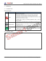
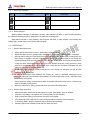
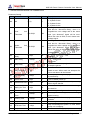
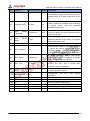
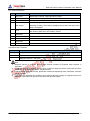
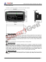
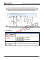
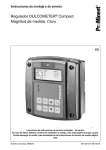
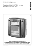
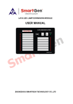
MGC100 PETROL GENSET CONTROLLER USER MANUAL SMARTGEN (ZHENGZHOU) TECHNOLOGY CO., LTD MGC100 Petrol Genset Controller User Manual CONTENT CONTENT ............................................................................................................................................2 1 OVERVIEW .......................................................................................................................................4 2 PERFORMANCE AND CHARACTERS ............................................................................................4 3 SPECIFICATION ...............................................................................................................................5 4 OPERATION......................................................................................................................................6 4.1 PUSHBUTTONS.........................................................................................................................6 4.2 CONTROL PANEL ......................................................................................................................6 4.2.1 Warn Icon Indication ............................................................................................................7 4.2.2 Panel Indicator: ....................................................................................................................7 4.3 OPERATION ...............................................................................................................................7 4.3.1 Remote Start Sequence: ......................................................................................................7 4.3.2 Remote Stop Sequence: ......................................................................................................7 4.3.3 Manual Start/Stop:................................................................................................................8 5 PROTECTION ...................................................................................................................................8 6 CONNECTION ..................................................................................................................................9 7 DEFINITION AND RANGE OF PARAMETERS ..............................................................................10 8 PARAMETERS SETTING ...............................................................................................................13 8.1 PARAMETERS REGULATION .................................................................................................13 8.2 RESTORE FACTORY SETTINGS ...........................................................................................13 8.3 ELIMINATE ACCUMULATED TIME .........................................................................................13 9 CASE DIMENSIONS .......................................................................................................................14 10 TYPICAL APPLICATION ...............................................................................................................15 11 FAULT FINDING ............................................................................................................................15 MGC100 Petrol Genset Controller Version 1.0 2015-06-29 Page 2 of 15 MGC100 Petrol Genset Controller User Manual Chinese trademark English trademark SmartGen — make your generator smart SmartGen Technology Co., Ltd. No.28 Jinsuo Road Zhengzhou Henan Province P. R. China Tel: 0086-371-67988888/67981888 0086-371-67991553/67992951 0086-371-67981000(overseas) Fax: 0086-371-67992952 Web: http://www.smartgen.com.cn http://www.smartgen.cn Email: [email protected] All rights reserved. No part of this publication may be reproduced in any material form (including photocopying or storing in any medium by electronic means or other) without the written permission of the copyright holder. Applications for the copyright holder’s written permission to reproduce any part of this publication should be addressed to Smartgen Technology at the address above. Any reference to trademarked product names used within this publication is owned by their respective companies. Smartgen Technology reserves the right to change the contents of this document without prior notice. Version Hsitory Date Version 2015-06-29 1.0 MGC100 Petrol Genset Controller Version 1.0 Content Original release. 2015-06-29 Page 3 of 15 MGC100 Petrol Genset Controller User Manual 1 OVERVIEW MGC100 Petrol Genset Controller is designed for start and protection of single genset. It allows manual and remote start/stop, data measurement, alarm indicate, shutdown protection functions. The controller fit with LED display, button-press operation, and it achieves precise measurement of various parameters, protection and control of genset. All of parameters can be configured from front panel. The controller which can be widely used in data display and fault protection of a number of small diesel and petrol genset with easy operation, reliable work, compact structure and simple connections. 2 PERFORMANCE AND CHARACTERS ——Multifunctional Nixie tube display, press button to operate; Switchable displayed battery: Generate voltage V Generate frequency Hz Accumulated running time(maximum is 9999h) H Battery voltage V ——There is a red LED on the panel for displaying working and alarm status; ——Chose to control Petrol Genset or Diesel Genset via connection; ——Suitable for 3-phase 4-wire, 3-phase 3-wire, 2-phase 3-wire, single phase 2-wire (120V/240V)systems with frequency 50/60/Hz; ——Protection function for gen under/over volt, over speed, fail to stop, emergency stop, high water temp, low oil pressure; when in protection, LED indicates alarm, and goes shutdown protection; ——Generator rotate speed can derive from gen frequency or rotate speed sensor; ——4-way digital input (high water temperature input, low oil pressure input, remote input, urgency stop input; ——2 relay output(start output, fuel output) and the fuel output is flexible output; ——1 flexible transistor output can be set to preheat output, alarm output, energize to stop output and idle output, etc; ——Two start success conditions (rotate speed sensor, generate) can be chosen; ——Parameter setting: parameters can be modified and stored in internal EEPROM memory and cannot be lost even in case of power outage; all of them can be adjusted using front panel of the controller; ——Modular design, anti-flaming ABS plastic enclosure, embedded installation way; compact structure with easy mounting. MGC100 Petrol Genset Controller Version 1.0 2015-06-29 Page 4 of 15 MGC100 Petrol Genset Controller User Manual 3 SPECIFICATION Item Working Voltage Overall Consumption Contents DC9.0V to 18.0V, continuous power supply (suitable for DC12V system) Regular working:<1W (Standby mode:<0.4W) AC Volt Input: 3-phase 4-wire AC 30V – AC 360V (ph-N) 3-phase 3-wire AC 50V – AC 620V (ph-ph) 2-phase 3-wire AC 30V – AC 360V (ph-N) Single phase 2-wire AC 30V – AC 360V (ph-N) AC Frequency 50Hz/60Hz Speed Sensor Voltage 1.0V to 24V(effective value) Speed Sensor Frequency 10000Hz(Max) Start Relay 7A DC12V power supply Fuel Relay 7A DC12V power supply Flexible Transistor 1A DC12V connect to (B+) Overall Dimensions 105.8mm x 61mm x 36.6mm Panel Cutout 92mm x 44mm Working Condition Temperature:(-25~+70)°C Storage Condition Temperature:(-25~+70)°C Protection Level IP55 Gasket Humidity:(20~93)%RH Apply AC2.2kV voltage between high voltage terminal and low Insulation voltage terminal; The leakage current is not more than 3mA within 1min. Weight 94g MGC100 Petrol Genset Controller Version 1.0 2015-06-29 Page 5 of 15 MGC100 Petrol Genset Controller User Manual 4 OPERATION 4.1 PUSHBUTTONS Buttons Description Icon Definition Explain Stop/- Stop the running genset. In stop status, press this button to stop generator immediately. In stop status, press this button to reset any shutdown alarm. In stop status, press this button for more than 2s to test if the nixie tube and panel indicator are right. In setting menu, upturn or decrease parameter value (it can be double-clicked) In setting menu, press this button for more than 3s to exit this menu. Page/Confirm Switch display contents of nixie tube in normal status. Pressing this button for more than 3 seconds entry the parameter configuration menu; In setting menu, press this button to modify and save value. Run/+ Manual start in stop status. In setting menu, downturn or increase parameter value (it can be double-clicked) 4.2 CONTROL PANEL MGC100 Petrol Genset Controller Version 1.0 2015-06-29 Page 6 of 15 MGC100 Petrol Genset Controller User Manual 4.2.1 Warn Icon Indication Icon Descripiton Emergency Shutdown Alarm Icon Descripiton Over Speed Alarm High Temp Alarm Low Oil Pressure Alarm Fail to Start Alarm Over/Under Volt Alarm 4.2.2 Panel Indicator: Working status indicator: in start delay duration, start indicator will blink; in other working duration, the indicator will always light; in stop status, the indicator will extinguish. Stop status indicator: in stop process, stop indicator will blink; in stop duration, the indicator will always light; in start status, the indicator will extinguish. 4.3 OPERATION 4.3.1 Remote Start Sequence: a) When remote start signal is active, ―Start Delay‖ timer is initiated; b) When start delay is over, preheat relay energizes (if configured), ―Preheat delay‖ is initiated; c) After the above delay, the Fuel Relay is energized, and then one second later (if configured), the Start Relay is engaged and the Preheat Relay switch off. If genset fails to fire during this cranking attempt then the fuel relay and start relay are disengaged for the pre-set rest period; ―crank rest time‖ begins and wait for the next crank attempt (after the ―crank rest time‖ delay start for 3s, preheat and ETS start to output; after ―crank rest time‖ finished, ETS switch off, and after fuel output for 1s, preheat switch off); d) Should this start sequence continue beyond the set number of attempts, the fail to start indicator will be illuminated. e) In case of successful crank attempt, the ―Safety On‖ timer is activated, allowing Low Oil Pressure Input and Under Pressure are inhibited. As soon as this delay is over, ―start idle‖ delay is initiated (if configured). f) During ―start idle‖ delay, under pressure alarm is inhibited. When this delay is over, ―warming up‖ delay is initiated (if configured). g) After the ―warming up‖ delay, genset will enter into Normal Running status. 4.3.2 Remote Stop Sequence: a) b) c) d) e) f) After remote start, when remote start signal is invalid, ―Stop Delay‖ timer is initiated; Once this ―stop delay‖ has expired, the ―Cooling Delay‖ is then initiated; During ―Stop Idle‖ Delay (if configured), idle relay is energized. ―ETS Solenoid Hold‖ begins, ETS relay is energized while fuel relay is de-energized. "Fail to Stop Delay" begins, complete stop is detected automatically. Genset is placed into standby mode after its ―After stop time‖. MGC100 Petrol Genset Controller Version 1.0 2015-06-29 Page 7 of 15 MGC100 Petrol Genset Controller User Manual 4.3.3 Manual Start/Stop: a) Press button to start genset. It will detect complete start and accelerates to high-speed running automatically. With high temperature, low oil pressure, over speed and volt abnormal during genset running, controller can protect it to stop quickly (Please refer to Start Sequence b-g) b) Press button to stop the running genset (Please refer to Stop Sequence b-f). Note a) The genset can be stopped manually in remote start status; at this time, remote input is inhibited and it will be active when remote input is closed again. b) After start conditions are satisfied, accumulative running timer will be initiated; at the same time, the last blinking decimal of nixie tube indicates that genset works normally. 5 PROTECTION 1) 2) 3) 4) 5) 6) 7) Low Oil Pressure: detect after Safety On, Alarm Stop when Low Oil Pressure input is active and lasts for 2s. High Temperature: detect when start, Alarm Stop when High Temperature is active and lasts for 2s. Over Speed: detect when start, Alarm Stop after duration exceeds Over Speed Stop Delay. Gen Over Volt: Alarm Stop when the controller detects genset voltage exceeds overvoltage value and delay exceeds abnormal delay. Gen Under Volt: Alarm Stop when the controller detects genset voltage less than undervoltage value and delay less than abnormal delay. Emergency Shutdown: ETS output immediately when Emergency Shutdown is active, in the meanwhile fuel, preheat and start signal are cut off and Emergency Shutdown Alarm Signal is send. Fail to Start: Alarm Stop when start failed in preset start times. MGC100 Petrol Genset Controller Version 1.0 2015-06-29 Page 8 of 15 MGC100 Petrol Genset Controller User Manual 6 CONNECTION No. Function 1 B- Cable Size Note 1.0mm2 Connected with negative of starter battery. 2 B+ 1.0mm2 Connected with negative of starter battery. If wire length is over 30m, better to double wires in parallel. Max. 10A fuse is recommended. 3 Start Relay Output 1.0mm2 B+ power is supplied by terminal 2, rated 4A. Connected with start coil of starter. 4 Fuel Relay Output 1.0mm2 B+ power is supplied by terminal 2, rated 4A. 5 Controller Types 1.0mm2 When this terminal short connected with (B+), it used as diesel genset controller. When this terminal connected with nothing, it used as petrol genset controller. 6 High Temperature 1.0mm2 Ground connected is active (B-) 1.0mm 2 Ground connected is active (B-) 1.0mm 2 Ground connected is active (B-) 1.0mm 2 Ground connected is active (B-) 1.0mm 2 B- power is supplied by terminal 1, rated 1A. 7 8 9 Low Oil Pressure Emergency Stop Remote Start 10 Aux. Transistor 11 Magnetic Pickup 2 (B-) has already connected 0.5mm2 with controller innerly. 12 Magnetic Pickup 1 0.5mm2 13 N 1.0mm2 14 15 16 W phase voltage monitor V phase voltage monitor U phase voltage monitor Connected with Rotate Speed Sensor, shielding line is recommended. Connected with N wire. 1.0mm 2 Connected with W phase (2 A fuse is recommended.) 1.0mm 2 Connected with V phase (2 A fuse is recommended.) 1.0mm 2 Connected with U phase (2 A fuse is recommended.) MGC100 Petrol Genset Controller Version 1.0 2015-06-29 Page 9 of 15 MGC100 Petrol Genset Controller User Manual 7 DEFINITION AND RANGE OF PARAMETERS Parameter Setting No. Content P00 P01 AC Over Threshold Volt Volt Parameter Range Default Description (0-3) 3 0:Single phase 2-wire 1: 2-phase 3-wire 2: 3-phase 3-wire 3: 3-phase 4-wire 264 When generate voltage exceed this value and last for ―Abnormal Delay‖, then it is regarded as over voltage and at the same time ―gen abnormal‖ signal will be sent. When set value is 620V, it won’t detect over voltage signal. 196 When generate voltage is under this value and last for ―Abnormal Delay‖, then it is regarded as under voltage and at the same time ―gen abnormal‖ signal will be sent. When set value is 30V, it won’t detect under voltage signal. (30-620)V P02 Under Threshold P03 Gen Abnormal (0-20)s Delay 10 Alarm delay value of generate over or under voltage. P04 Start Delay (0-3600)s 1 Time from remote start signal is active to start the genset. P05 Stop Delay (0-3600)s 1 Time from remote stop signal is deactivated to stop the genset. (30-620)V P06 Start Attempts (1-10) 3 It is maximum of start attempts when starter failed to start. When reach set attempts the fail to start alarm will be initiated. P07 Preheat Delay (0-300)s 0 Time of pre-powering heat plug before starter is powered up. P08 Crank Time (3-60)s 8 Time of starter power up. P09 Crank Rest Time (3-60)s 10 The waiting time before second power up when engine start fail. P10 Safety On Time (1-60)s 10 Alarms for low oil pressure and under voltage are inactive. P11 Start Idle Time (0-3600)s 0 Idle running time of genset when starting. P12 Warming Time (3-3600)s 10 Warming time between genset close and high speed running. P13 Cooling Time (3-3600)s 10 Radiating time before stop genset, after it unloads. P14 Stop Idle Time (0-3600)s 0 dle running time when pump unit stop. P15 ETS Hold Time (0-120)s 20 Stop electromagnet’s power on time when pump unit is stopping. P16 Stop Time (0-120)s 0 Time between ending of pump unit idle delay Up MGC100 Petrol Genset Controller Version 1.0 2015-06-29 Page 10 of 15 No. MGC100 Petrol Genset Controller User Manual Parameter Range Default Description Content and stopped when ―ETS time‖ is set as 0; Time between ending of ETS hold delay and stopped when ―ETS Hold output time‖ is not 0. 118 Teeth number of the engine, for judging of starter separation conditions and inspecting of engine speed. See the following Installation Instruction. 1710 When rotate speed exceed this value and last for the delay, over speed shutdown alarm signal will be sent. (0-20)s 2 When rotate speed exceed over speed threshold and last for the delay, over speed alarm signal will be sent. (2-16) 2 Set genset poles. 2 Disconnected condition. Separate condition of starter and engine are gen sensor and magnetic sensor, in order that separate stater motor and engine as soon as possible. P17 Flywheel Teeth P18 Over Speed (0-6000)r/min Threshold P19 Over Delay P20 Poles P21 Speed Disc. Condition (10-300) (0-2) P22 Disc. Speed (0-6000)r/min 360 In starting process, if genset rotate speed exceed this value, it is regarded as genset start success, starter will separate. P23 Disc. Freq (10-30)Hz 14 In starting process, if genset frequency exceed this value, that is genset start success, starter will separate. P24 Fuel Select (0-1) 0 0: Fuel output. 1: Stop output(ETS output) P25 Aux. Output 1 (0-9) 0 Configuration Defination‖ CLb1 Ua Correct A phase voltage value. CLb2 Ub Correct B phase voltage value. CLb3 Uc Correct C phase voltage value. CLb4 Uab Correct AB wire voltage. CLb5 Ubc Correct BC wire voltage. CLb6 Uca Correct CA wire voltage. Output MGC100 Petrol Genset Controller Version 1.0 see 2015-06-29 form ―Aux. Output Page 11 of 15 MGC100 Petrol Genset Controller User Manual Aux. Output Defination No. Content Description 0 Not Used When this is chosen, output port won’t output. 1 Preheat Close before start, open before energize. 2 Common Alarm When stop alarm is initiated, this alarm will self-lock untill alarm reset. 3 Idle Output Used for engine which has idles. Close before starting and open in warming up delay; Close during stopping idle process and open when stop is completed. 4 ETS Used for some genset which has stop magnetic. Close before stoping idle ended. Open when ―ETS Delay‖ ended. 5 Reserved 6 Reserved 7 Reserved 8 Reserved 9 Reserved Crank Success Conditions No. Content 0 Magnetic Sensor 1 Generate 2 Magnetic Sensor + Generate Note: 1) 2) 3) 4) Magnetic sensor is magnetic device which detects numbers of flywheel teeth installed in generator. If magnetic sensor is selected, please insure numbers of flywheel teeth is same with set value, otherwise, ―Over Speed Shutdown‖ maybe caused. If genset without magnetic sensor, please don’t select corresponding items, otherwise, ―start fail‖ maybe caused. If generate isn’t selected, the controller won’t detect over/under voltage; if magnetic sensor isn’t selected, rotate speed of genset is converted via generate signal. MGC100 Petrol Genset Controller Version 1.0 2015-06-29 Page 12 of 15 MGC100 Petrol Genset Controller User Manual 8 PARAMETERS SETTING 8.1 PARAMETERS REGULATION When the controller is running, press will display for 3s, it will enter into parameter number menu and LED : 1) Press and 2) After parameter number is selected, press and to downturn/upturn parameter number; to enter into parameter setting menu; press to increase/decrease parameter value (it can be double-clicked); 3) Press to confirm modification and save value; 4) For multiple parameters, step (1-3) can be repeat done for setting; 5) After parameter setting, press for 3s to exit parameter setting status. 8.2 RESTORE FACTORY SETTINGS In emergency stop input status, press and for 5s at the same time, it can restore to default and ―reset‖ will be displayed on LED. 8.3 ELIMINATE ACCUMULATED TIME Press and for 5s at the same time, accumulated running time will be reset an ―hclr‖ will be displayed on LED. Note: ——Over voltage threshold must be greater than under voltage threshold. ——When start successfully, generator frequency need to be set lower as soon as possible in order to starter separate sooner. ——Number of setting contents refers to ―Parameter Setting‖(7). ——Only in parameter number menu can exit from parameter setting status. If there is no press operation in parameter number menu, it will exit in 30s automatically. MGC100 Petrol Genset Controller Version 1.0 2015-06-29 Page 13 of 15 MGC100 Petrol Genset Controller User Manual 9 CASE DIMENSIONS Controller is panel built-in design; it is fixed by clips when installed. 1) Battery Voltage Input NOTE: MGC100 controller can suit for widely range of battery voltage DC(9~18)V. Negative of battery must be connected with the engine shell soundly. The diameter of wire which from power supply to battery must be over 1.0mm2. If floating charge configured, please firstly connect output wires of charger to battery’s positive and negative directly, then, connect wires from battery’s positive and negative to controller’s corresponding input ports in order to prevent charge disturbing the controller’s normal working. Warn: In running process, removing start battery is strictly prohibit. 2) Speed Sensor Input Note: Speed sensor is magnetic equipment which is installed on engine body for testing flywheel teeth number. 2 core shielding wire is used for the connection of the sensor and controller. The wire is supposed to be connected to 11 terminal of controller with one end and the other end hanging in the air. The other two signal lines connect separately to 11,12 terminal. Speed sensor output voltage is supposed to be at AC (1-24)V (virtual value) when it is in full speed range, and AC12V (when in rated rotate speed) is recommened. When install the speed sensor, screw it to contact the flywheel firstly, inverse it with 1/3 circle, and then tighten the nut finally. 3) Withstand Voltage Test Caution: When controller has been installed in control panel, if the high voltage test is needed, please disconnect controller’s all terminals in order to prevent high voltage into controller and damage it. MGC100 Petrol Genset Controller Version 1.0 2015-06-29 Page 14 of 15 MGC100 Petrol Genset Controller User Manual 10 TYPICAL APPLICATION Note: when it controls petrol genset, terminal 4 connects with ignition control; when it controls diesel genset, terminal 5 needs to short connect with B+, terminal 4 needs to connect with fuel output. 11 FAULT FINDING Symptoms Controller no response with power. Possible Solutions Check starting batteries; Check controller connection wirings; Check DC fuse. Crank not disconnect Check fuel oil circuit and its connections; Check starting batteries; Check speed sensor and its connections; Refer to engine manual. Shutdown Alarm in running Check related switch and its connections according to the information on LED; Starter no response Check starter connections; Check starting batteries. _________________________________ MGC100 Petrol Genset Controller Version 1.0 2015-06-29 Page 15 of 15