1
Operation instruction
ion
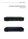
LM-MX444-HD4K2K HDMI Matrix
Operating Instruction
ion
Operation instruction
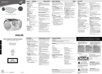
Thank you for purchasing this product. For optimum performance and safety, please read these
instructions carefully before connecting, operating or adjusting this product. Please keep this manual for
future reference.
Surge Protection Device Recommended
This product contains sensitive electrical components that may be damaged by electrical spikes, surges,
electric shock, lightning strikes, etc. Use of surge protection systems is highly recommended in order to
protect and extend the life of your equipment.
ion
Operation instruction
Table of Contents
1.Introduction . . . . . . . . . . . . . . . . . . . . . . . . . . . . .. . . . . . . . . . . . . . . . . . . . . . . . . . . . . . . . . . . . . . . . 4
2.Features . . . . . . . . . . . . . . . . . . . . . . . . . . . . . . . . . . . . . . . . . . . . . . . . . . . . . . . . . . . . . . . . . . . . . . . 4
3.Panel Descriptions. . . . .... . . . . . . . . .. . . . . . . . . .. . . . . . . . .. . . . . . . . .... . . .. . . . . . . . . .. . . . . . . . .4
4. Remote Control Descriptions .. .. . . . . . . .. . . . .. . . . .. .. . .. . . . . . .. . . . . . .. . . . . . …………. .. . . . 6
5.Application Diagram. . . . . . . .. . . .. . . . . .. . . . . .. . . .. .. .. . . . . .. . . . . .. . . . . . .. . . . . .. . . . . ……. . 7
6.Specifications . . . . . . . . ... . . . . . . . . . . . . . .. . . . . . . . . . . . . . . . . . . . . . . . . . . . . . . . . . . . . . . . . . . . 8
7. Package Contents . . . . . . . . . . . . . . . . . . . . . . . . . . . . . . . …... . . . . . . . . . . . . . . . . . . . . . . . . . . . . . 8
8.RS232 Pin Assignment . . . . . . …………………. . . . . .. . . . . . . . . . . . . . . . . . . . . . . . . . . . . . . . . . . 9
9.DIP for EDID Setting . . . . . . . . . . . . . . . . . . . . . . . .. . . . . . . . . ….. . . . . . . . . . . . . . . . . . . . . . . . . . 9
10.GUI control . . . . . . . . . . . . . . . . ……... . . . . . . . . . . . . . . . . . . . . . . . . . . . . . . . . . . . . . . . . . . . . . 1 0
11. RS-232 Commands ................................................... ........................................ ............... ...........19
12.Warranty Policy . . . . . . . . . . . . ………………. . . . . . . . . . .. . .. . . . . . . . . . . . . . . . . . . . . . . . . . . 20
ion
Instruction
Operation instruction
The LM-MX444-HD4K2K 4×4 Matrix with IR matrix for HDMI routes four Hi-Def sources to any
four HDTV displays, supporting 1080p Full HD up to 4K plus all 3D formats, along with
multichannel digital audio formats such as Dolby® True HD and DTS-HD® Master Audio™. Each
source can be routed to any display using the front-panel push buttons, IR remote control, and RS-232
interface.
Features:
1. Supports resolutions up to 1080p@60HZ,48-bit deep color, 4k@30HZ
2. Allows any source to be displayed on multiple displays at the same time
3. Allows any HDMI display to view any HDMI source at any time
4. Dolby TrueHD and DTS-HD master audio pass through HDMI output
5. Advanced EDID management for rapid integration of sources and displays
6. Multiple switching mode, push-in button, IR remote control,and RS-232 control
7. Easy installation with rack-mounting ears
8. Full 3D pass- through.
9. HDCP compliant
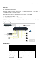
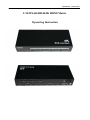
Panel Descriptions
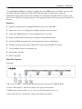
Front Panel
1. IR receiver window----Receive the IR from the remote control of SX-MX444-4K2K.
2. Power LED indicator---Indicate the status of the power for the matrix.
3. HDMI output selection button 1 to 4---Press to select the output from 1 to 4.
4. Input LED indicator---Indicate the status of the input for the matrix.
ion
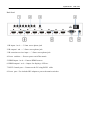
Back Panel
1. IR inputs 1 to 4 ---- 3.5mm stereo phone-jack
2. IR outputs 1 to4 ---- 3.5mm stereo phone-jack
3. IR extension receiver input ---- 3.5mm stereo phone-jack
4. Power switcher---- Press to power on/off the matrix
5. HDMI inputs 1 to 4----Connect HDMI sources
6. HDMI outputs 1 to 4----Output for displays, AVR etc.
7. RS232 female port----Connect to the PC using RS232 cable
8. Power port---Use included DC adaptor to power the matrix switcher
O perat ion inst ruct
ion
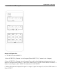
Remote
Control Description
O perat ion inst ruct
Output and Input select
A. OUTPUT-X select INPUT-Y:
1. Press OUTPUT-X (X means 1 to 4 of outputs)7Press INPUT-Y ( Y means 1 to 4 of inputs )
2. Press OUTPUT-X (X means 1 to 4 of outputs)7 press the left and right arrow buttons to select the
input. B. All outputs select INPUT-Y: Press ALL button in zone OUTPUT7Press INPUT-Y button ( Y
means 1 to 4 of inputs ), then INPUT-Y switched to ALL OUTPUTS
C. Mirror all inputs and outputs (Ex. Input 1 to output 1, input 2 to output 2, etc): Press PTP button in
Zone OUTPUT
O perat ion inst ruct
ion
EDID Set Up
A. Fixed EDID to INPUT-Y/ALL
Press 1080I/1080P/3D/4K→Press 2.0CH/5.1CH/7.1CH→INPUT-Y/ALL button in Zone INPUT B.
Copy EDID of OUTPUT-X to INPUT-Y/ALL
Press COPY button→ Press OUTPUT-X button→ Press INPUT-Y/ALL button
C. User defined EDID to INPUT-Y/ALL
Press USER1/USER2 button→ Press INPUT-Y/ALL
NOTE: Pressing button sequence should be finished in 5 seconds, otherwise, operation discarded.
Application Diagram
Specifications:
Bandwidth:
2.97Gbps per color
Video Input Connectors: 4x HDMI Type A, 19-pin, female, locking
Video Output
4x HDMI Type A, 19-pin, female, locking
RS-232
serial port:
DB-9, female
Connectors:
IR Input ports:
5x 3.5mm stereo jack
IR Output ports:
4x 3.5mm stereo jack
Rack-Mountable:
Rack ears included
Dimensions (W x H x 256mm x 114mm x 43mm , without feet
Shipping
Weight:
1.0kg
D):
Operating Temperature: 32°F to 104°F (0°C to 40°C)
Storage Temperature : -4°F to 140°F (-20°C to 60°C)
Power Supply:
12V/2A DC
O perat ion inst ruct
ion
Package
Contents:
1.
1x LM-MX444-HD4K2K
2.
1x 12V DC power supply
3.
1x Remote control
4.
4x IR Transmitter,
5.
5x IR Receiver.
6.
1x mounting kit.
7.
1x CD for control software & user manual
RS-232 Pin Assignment
Matrix
PIN
1
Assignment
NC
Remote Control Console
PIN Assignment
1
NC
2
Tx
2
Rx
3
Rx
3
Tx
4
NC
4
NC
5
GND
5
GND
6
NC
6
NC
7
NC
7
NC
8
NC
8
NC
9
NC
9
NC
Baud Rate: 57600 bps
Data Bit: 8-bit Parity: None Stop Bit: 1-bit
Flow Control: None
O perat ion inst ruct
ion
DIP for EDID Setting
[DIP]=0000: HDMI 1080p@60Hz, Audio 2CH PCM
[DIP]=0001: HDMI 1080p@60Hz, Audio 5.1CH PCM/DTS/DOLBY [DIP]=0010: HDMI
1080p@60Hz, Audio 7.1CH PCM/DTS/DOLBY/HD [DIP]=0011: HDMI 1080i@60Hz, Audio 2CH
PCM
[DIP]=0100: HDMI 1080i@60Hz, Audio 5.1CH PCM/DTS/DOLBY [DIP]=0101: HDMI
1080i@60Hz, Audio 7.1CH PCM/DTS/DOLBY/HD [DIP]=0110: HDMI 1080p@60Hz/3D, Audio
2CH PCM
[DIP]=0111: HDMI 1080p@60Hz/3D, Audio 5.1CH PCM/DTS/DOLBY [DIP]=1000: HDMI
1080p@60Hz/3D, Audio 7.1CH PCM/DTS/DOLBY/HD [DIP]=1001: HDMI 4K2K, Audio 2CH PCM
[DIP]=1010: HDMI 4K2K, Audio 5.1CH PCM/DTS/DOLBY [DIP]=1011: HDMI 4K2K, Audio
7.1CH PCM/DTS/DOLBY/HD [DIP]=1100: DVI 1280x1024@60Hz, Audio None
[DIP]=1101: DVI 1920x1080@60Hz, Audio None
[DIP]=1110: DVI 1920x1200@60Hz, Audio None
GUI Control
PC System: Microsoft Windows Operation System
Installation
4x4 HDMI Matrix controller is a green software. You just need to copy “4x4 HDMI Matrix Controller
vx.x.exe” to the PC which is used to control the Matrix by RS232 COM or TCP to complete
installation.
Preparation
1.
Connect PC and Matrix by RS232 cable
2.
Power up Matrix (It will take about 5 seconds to be ready with “Di” beep sound )
3.
Double click “4x4 HDMI Matrix Controller vx.x.exe” icon to run it
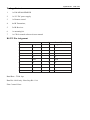
How to control Matrix
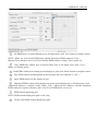
Common information
Click to select tab page
1
2
1 COM port connect status
3
4
O perat ion inst ruct
ion
2 Control command process status
3 Prompt message display area
4 Date and Time display
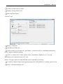
“General” page
①
⑥
②
⑦
③
④
⑤
1 RS232 COM mode
2 List detected COM ports
3 Click to connect or disconnect PC and Matrix ( Connection will be established automatically
before control commands sending )
4 Click to refresh device status: include device information displayed in ⑤ area and
Input/output port connection status in ⑥ area.
NOTE: Tab pages cannot be changed during control command is processing.
5 To enable or disable Input/output tags displaying when setting buttons on “Setting” page focused
6 Device information display area
O perat ion inst ruct
ion
7 Input/output port connection status
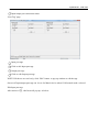
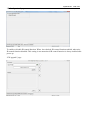
“Port Tag” page
①
③
②
④
1 Input port tags
2 Click to edit Input port tags
3 Output port tags
4 Click to edit Output port tags
NOTE: Edit boxes are read only, click “Edit” button to pop up window to edit the tags
One set of Input/output port tags can be set for Matrix device when COM control mode selected.
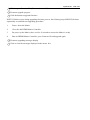
Edit Input port tags
After action of ②, edit form will pop-up as below:
Operation instruction
Define tags for respective Input port, then devices connect the Input ports can be easily remembered.
Click buttons with “×” caption to delete tag which is no use any more, if tag is still used by any other
Input port, delete action will be discarded.
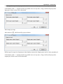
Edit Output port tags
After action of ④, edit form will pop-up as below:
Define tags for respective Output port, then displays connect the Output ports can be easily remembered.
Click buttons with “×” caption to delete tag which is no use any more, if tag is still used by any other
Output port, delete action will be discarded.
Operation instruction
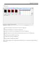
“Setting” page
①
⑤
②
③
⑥
④
⑦
1 LED which displays Input number for respective Output port
2 Click to select Input port for respective Output port
3 Click to select previous or next Input port for respective Output port
4 Display Output from Input with tag information when mouse moves over ② buttons
5 Pre-Setting items: Default is Port to Port
6 Click to edit selected pre-setting item
7 Set selected pre-setting item to Matrix
NOTE: When Change to this “Setting” page, software will try to refresh source selection status of
Output port.
ion
O perat ion inst ruct
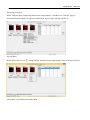
Pop-up tag messages
When “Display Input, Output tags when focus setting buttons” checkbox on “General” page is
checked and Input/output port tag has been defined, tag messages will pop up like as:
Pop-up Menu
When mouse moves over ② setting buttons, and click mouse right button, menu will pop up like as:
All Outputs: All Outputs from same Input
O perat ion inst ruct
ion
“1 Output” to “4 Outputs”: Set current Output (where mouse right clicked) and the next x-1 ( x range is
from 1 to 4, set total x Outputs at the same time ) Output(s) from same Input
Port to Port: Output1 from Input1, Output2 from Input2, Output3 from Input3, etc.
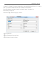
Edit selected pre-setting item
After action of ⑥, edit form will pop-up as below:
①
③
1 Pre-Setting name
2 Set all Output ports from same Input
3 Select Input for respective Output
②
ion control” page
“EDID
1
O perat ion inst ruct
Set EDID mode for selected Input port or All Input ports, click “Set” button to complete action.
NOTE: When set User1/User2 EDID mode, should Download EDID content to User1
Memory/User2 Memory first. User1/User2 default EDID content is 1080p, Stereo Audio 2.0.
2
Copy EDID from Output port to selected Input port or All Input ports, click “Copy”
button to complete action.
3
Read EDID content from Output port and display in grid, click “Read” button to complete action.
4
Save EDID content which displayed in grid to binary file (file extension is “.bin”)
5
Open EDID binary file and display in grid
6
Download EDID content which displayed in grid to selected Input port or All Input ports, click
“Download” button to complete action. When User1 Memory/User2 Memory selected, download
EDID content to respective memory then User1/User2 EDID mode can be set.
7
EDID content displaying grid
NOTE: EDID content displayed in grid is read only.
8
Click to clear EDID content displayed in grid
“IRion
Configuration” page
O perat ion inst ruct
To enable or disable IR control function. When box checked, IR control function enabled, otherwise,
IR control function disabled. This setting is not memorized. IR control function is always enabled after
power up.
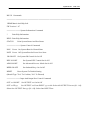
“FW upgrade” page
ion
1 Click to open firmware file (file extension is “.fw”).
O perat ion inst ruct
2 Firmware upgrade progress
3 Click the button to upgrade firmware.
NOTE: If failure occurs during upgrading firmware process, the following steps SHOULD be done
sequentially to establish next upgrading procedure:
1.
Power down the Matrix
2.
Close the 4x4 HDMI Matrix Controller
3.
Re-power up the Matrix, then wait for 10 seconds to ensure the Matrix is ready
4.
Run 4x4 HDMI Matrix Controller, open firmware file and upgrade again
4 Firmware upgrading messages display
5 Click to clear the messages displayed in the memo box.
O perat ion inst ruct
ion
RS-232 Commands
================================================================
HDMI Matrix-4x4 Help Info
FW Version: 1.67
============= System Information Command
?
Print Help Information
HELP Print Help Information
STATUS
Print System Status And Port Status
============= System Control Command
PON
Power On, System Run On Normal State
POFF Power Off, System Run On Power Save State
IR ON/OFF Set System IR Control On Or Off
KEY ON/OFF
Set System KEY Control On Or Off
APM ON/OFF
Set Advanced Process Mode On Or Off
BEEP ON/OFF
Set Onboard Beep On Or Off
RESET
Reset System To Default Setting
(Should Type "Yes" To Confirm, "No" To Discard)
============= Input And Output Port Control Command
OUT xx ON/OFF Set OUTPUT: xx On Or Off
OUT xx FR yy
Set OUTPUT: xx From INPUT: yy xx=00: Select All OUTPUT Port xx=[01...04]:
Select One OUTPUT Port yy=[01...04]: Select One INPUT Port
O perat ion inst ruct
ion
EDID xx CP yy
Set Input: xx EDID Copy From Output: yy
EDID xx DF zz Set Input: xx EDID To Default EDID: zz xx=00: Select All INPUT Port
xx=[01...04]: Select One INPUT Port yy=[01...04]: Select One OUTPUT Port
zz=00: HDMI 1080p@60Hz, Audio 2CH PCM
zz=01: HDMI 1080p@60Hz, Audio 5.1CH PCM/DTS/DOLBY zz=02: HDMI 1080p@60Hz, Audio
7.1CH PCM/DTS/DOLBY/HD zz=03: HDMI 1080i@60Hz, Audio 2CH PCM
zz=04: HDMI 1080i@60Hz, Audio 5.1CH PCM/DTS/DOLBY zz=05: HDMI 1080i@60Hz, Audio
7.1CH PCM/DTS/DOLBY/HD zz=06: HDMI 1080p@60Hz/3D, Audio 2CH PCM
zz=07: HDMI 1080p@60Hz/3D, Audio 5.1CH PCM/DTS/DOLBY zz=08: HDMI 1080p@60Hz/3D,
Audio 7.1CH PCM/DTS/DOLBY/HD zz=09: HDMI 4K2K, Audio 2CH PCM
zz=10: HDMI 4K2K, Audio 5.1CH PCM/DTS/DOLBY zz=11: HDMI 4K2K, Audio 7.1CH
PCM/DTS/DOLBY/HD zz=12: DVI 1280x1024@60Hz, Audio None
zz=13: DVI 1920x1080@60Hz, Audio None zz=14: DVI 1920x1200@60Hz, Audio None
================================================================
ion information
Safety
O perat ion inst ruct
safeguards
To reduce the risk of electric shock, do not expose this product to rain or moisture
PRODUCT SERVICE
1) Damage requiring service: The unit should be serviced by qualified service personnel if:
(a)The DC power supply cord or AC adaptor has been damaged;
(b)Objects or liquids have gotten into the unit;
(c)The unit has been exposed to rain;
(d)The unit does not operate normally or exhibits a marked change in performance;
(e)The unit has been dropped or the cabinet damaged.
2) Servicing Personnel: Do not attempt to service the unit beyond that described in these operating
instructions. Refer all other servicing to authorized servicing personnel.
3) Replacement parts: When parts need replacing ensure the servicer uses parts specified by the
manufacturer or parts that have the same characteristics as the original parts. Unauthorized substitutes
may result in fire, electric shock, or other hazards.
4) Safety check: After repairs or service, ask the servicer to perform safety checks to confirm that the
unit is in proper working condition.
WARRANTY
If your product does not work properly because of a defect in materials or workmanship, our Company
(referred to as "the warrantor" ) will , for the length of the period indicated as below,
(Parts(1)Year ,Labor(90) Days) which starts with the date of original purchase ("Limited Warranty
period"), at its option either(a) repair your product with new or refurbished parts, or (b) replace it with a
new of a refurbished product. The decision to repair or replace will be made by the warrantor.
During the "Labor" Limited Warranty period there will be no charge for labor.
During the "Parts" warranty period, there will be no charge for parts. You must mail-in your product
during the warranty period. This Limited Warranty is extended only to the original purchaser and only
covers product purchased as new. A purchase receipt or other proof of original purchase date is required
for Limited Warranty service.
Mail-In Service
When shipping the unit carefully pack and send it prepaid, adequately insured and preferably in the
original carton. Include a letter detailing the complaint and provide a day time phone and/or email
address where you can be reached.
ion
LIMITED
WARRANTY LIMITS AND EXCLUSIONS
O perat ion inst ruct
1) This Limited Warranty ONLY COVERS failures due to defects in materials or workmanship, and
DOES NOT COVER normal wear and tear or cosmetic damage. The Limited Warranty ALSO DOES
NOT COVER damages which occurred in shipment, or failures which are caused by products not
supplied by warrantor, or failures which result from accidents, misuse, abuse, neglect, mishandling,
misapplication, alteration, faulty installation, set-up adjustments, misadjustment of consumer controls,
improper maintenance, power line surge, lightning damage, modification, or service by anyone other
than a Factory Service center or other Authorized Servicer, or damage that is attributable to acts of God.
2) THERE ARE NO EXPRESS WARRANTIES EXCEPT AS LISTED UNDER "LIMITED
WARRANTY COVERAGE".THE WARRANTOR IS NOT LIABLE FOR INCIDENTAL OR
CONSEQUENTIAL DAMAGES RESULTING FROM THE USE OF THIS PRODUCT, OR
ARISING OUT OF ANY BREACH OF THIS WARRNTY. (As examples, this excludes damages for
lost time, cost of having someone remove or re-install an installed unit if applicable, travel to and from
the service, loss of or damage to media or images, data or other recorded content. The items listed are
not exclusive, but are for illustration only.)
3) PARTS AND SERVICE, WHICH ARE NOT COVERED BY THIS LIMITED WARRANTY, ARE
YOUR RESPONSIBILITY.