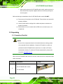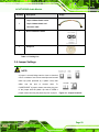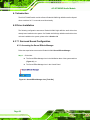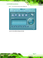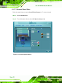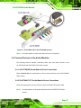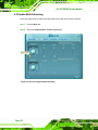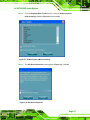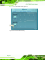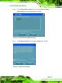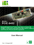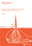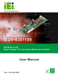
1
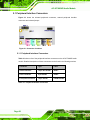
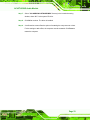
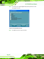
AC-KIT-883HD Audio Module
Page 1
AC-KIT-883HD Audio Module
Revision
MODEL
AC-KIT-883HD Audio Module
Revision Number
Description
Date of Issue
1.0
Initial release
December 2006
Page 2
AC-KIT-883HD Audio Module
Copyright
COPYRIGHT NOTICE
The information in this document is subject to change without prior notice in order to
improve reliability, design and function and does not represent a commitment on the part
of the manufacturer.
In no event will the manufacturer be liable for direct, indirect, special, incidental, or
consequential damages arising out of the use or inability to use the product or
documentation, even if advised of the possibility of such damages.
This document contains proprietary information protected by copyright. All rights are
reserved. No part of this manual may be reproduced by any mechanical, electronic, or
other means in any form without prior written permission of the manufacturer.
TRADEMARKS
IBM PC is a registered trademark of International Business Machines Corporation. INTEL
is a registered trademark of INTEL Corporation. Other product names mentioned herein
are used for identification purposes only and may be trademarks and/or registered
trademarks of their respective owners.
Page 3
AC-KIT-883HD Audio Module
Packing List
NOTE:
If any of the components listed in the checklist below are missing,
please do not proceed with the installation. Contact the IEI reseller or
vendor you purchased the AC-KIT-883HD audio module from or
contact an IEI sales representative directly. To contact an IEI sales
representative, please send an email to [email protected].
The items listed below should all be included in the AC-KIT-883HD audio module
package.
1 x AC-KIT-883HD audio module c/w slot bracket
1 x 10-pin 2.00mm female end to10-pin 2.00mm female end connector cable
1 x Quick installation guide (QIG)
1 x Utility CD
Images of the above items are shown in Chapter 3.
Page 4
AC-KIT-883HD Audio Module
Table of Contents
1
INTRODUCTION....................................................................................................11
1.1 AC-KIT-883HD AUDIO MODULE OVERVIEW .......................................................... 12
1.2 PRODUCT SPECIFICATIONS ....................................................................................... 13
1.2.1 Interface Specifications.................................................................................... 13
1.2.2 Audio Processing ............................................................................................. 13
1.2.3 Functionality .................................................................................................... 13
1.2.4 Software Support.............................................................................................. 14
1.3 SYSTEM REQUIREMENTS .......................................................................................... 14
1.4 DIMENSIONS ............................................................................................................ 15
1.5 REALTEK ALC883 AUDIO CODEC............................................................................ 16
1.5.1 Features ........................................................................................................... 16
1.5.2 Applications ..................................................................................................... 18
2
CONNECTORS ...................................................................................................... 19
2.1 PERIPHERAL INTERFACE CONNECTORS .................................................................... 20
2.1.1 Peripheral Interface Connectors ..................................................................... 20
2.1.2 Audio Connector .............................................................................................. 21
2.1.3 CD In Connector.............................................................................................. 22
2.1.4 Front Panel Connector .................................................................................... 23
2.2 EXTERNAL PERIPHERAL INTERFACE CONNECTORS .................................................. 24
3
INSTALLATION .................................................................................................... 25
3.1 ANTI-STATIC PRECAUTIONS ...................................................................................... 26
3.2 INSTALLATION CONSIDERATIONS ............................................................................. 27
3.2.1 Installation Notices .......................................................................................... 27
3.3 UNPACKING.............................................................................................................. 28
3.3.1 Unpacking Checklist ........................................................................................ 28
3.4 JUMPER SETTINGS .................................................................................................... 29
3.4.1 AVDD Power ON Select Jumper...................................................................... 30
3.5 CHASSIS INSTALLATION ........................................................................................... 30
3.6 REALTEK HD AUDIO DRIVER (ALC883) INSTALLATION ......................................... 32
Page 5
AC-KIT-883HD Audio Module
4
7.1 SURROUND SOUND CONFIGURATION ................................................... 35
4.1 INTRODUCTION ........................................................................................................ 36
4.2 DRIVER INSTALLATION ............................................................................................. 36
4.3 7.1 SURROUND SOUND CONFIGURATION ................................................................. 36
4.3.1 Accessing the Sound Effects Manager ............................................................. 36
4.3.2 7.1 Surround Sound Setup................................................................................ 38
4.3.3 Connect Devices to the Audio Module............................................................. 39
4.3.4 Testing Speaker Configuration......................................................................... 43
5
MULTI-STREAMING CONFIGURATION ........................................................ 45
5.1 INTRODUCTION ........................................................................................................ 46
5.2 DRIVER INSTALLATION ............................................................................................. 46
5.3 INTERFACING THE IO-KIT-MULTI-ST AUDIO MODULE .......................................... 46
5.4 CONNECT DEVICES TO THE AUDIO MODULES .......................................................... 47
5.4.1 AC-KIT-883HD Audio Module Device Connections ....................................... 47
5.4.2 IO-KIT-MULTI-ST Audio Module Device Connections................................... 47
5.5 ENABLE MULTI-STREAMING .................................................................................... 52
5.6 MUTE PLAYBACK DEVICES ...................................................................................... 56
5.7 INITIATE MULTI-STREAMING APPLICATIONS ............................................................. 58
5.7.1 Primary Audio Streaming Application ............................................................. 58
5.7.2 Secondary Audio Streaming Application ......................................................... 62
INDEX.............................................................................................................................. 69
Page 6
AC-KIT-883HD Audio Module
List of Figures
Figure 1-1: AC-KIT-883HD Audio Module Overview ................................................12
Figure 1-2:Module Dimensions (units: mm) .............................................................15
Figure 2-1: Connector Locations...............................................................................20
Figure 2-2: Audio Connector Schematic...................................................................21
Figure 2-3: CD In Connector Schematic ...................................................................22
Figure 2-4: Front Panel Connector Schematic.........................................................23
Figure 3-1: Jumper Locations....................................................................................29
Figure 3-2: Connect Audio Module to Motherboard ................................................31
Figure 3-3: Connect Audio Module to CD .................................................................32
Figure 4-1: Sound Effect Manager Icon [Task Bar]..................................................36
Figure 4-2: Sound Effects Manager (ALC883)..........................................................37
Figure 4-3: 8 Channel Speaker Option ......................................................................38
Figure 4-4: 7.1 Surround Sound Speaker Layout ....................................................39
Figure 4-5: Connected Device Screen.......................................................................40
Figure 4-6: Front Speaker as Line Out ......................................................................41
Figure 4-7: Side Speakers as Side Speaker Out ......................................................42
Figure 5-1: IO-KIT-MULTI-ST to AC-KIT-883HD Interface........................................47
Figure 5-2: Connected Device Screen.......................................................................48
Figure 5-3: IO-KIT Speaker as Line Out ....................................................................49
Figure 5-4: Connected Device Screen.......................................................................50
Figure 5-5: IO-KIT Microphone as Mic In ..................................................................51
Figure 5-6: Access Playback Multi-streaming..........................................................52
Figure 5-7: Enable Playback Multi-streaming ..........................................................53
Figure 5-8: New Device Reminder .............................................................................53
Figure 5-9: Access Record Multi-streaming.............................................................54
Figure 5-10: Enable Recording Multi-streaming ......................................................55
Figure 5-11: New Device Reminder ...........................................................................55
Figure 5-12: Setting the Default Playback Device....................................................56
Page 7
AC-KIT-883HD Audio Module
Figure 5-13: Mute All Playback Devices ...................................................................58
Figure 5-14: Windows Media Player Tools Menu.....................................................59
Figure 5-15: Windows Media Player Devices ...........................................................60
Figure 5-16: Windows Media Player Speaker Options ............................................61
Figure 5-17: Skype Tools Menu .................................................................................62
Figure 5-18: Skype Options Window.........................................................................63
Figure 5-19: Skype Audio In Device ..........................................................................64
Figure 5-20: Skype Audio Out Device .......................................................................65
Figure 5-21: Skype Ringing Device ...........................................................................66
Figure 5-22: Skype Call...............................................................................................67
Page 8
AC-KIT-883HD Audio Module
List of Tables
Table 1-1: Interface Specifications ............................................................................13
Table 1-2: Audio Processing Capabilities ................................................................13
Table 1-3: Functionality ..............................................................................................13
Table 1-4: Software Support ......................................................................................14
Table 2-1: Peripheral Interface Connectors..............................................................20
Table 2-2: Audio Connector Pinouts .........................................................................21
Table 2-3: CD In Connector Pinouts..........................................................................22
Table 2-4: Front Panel Connector Pinouts ...............................................................23
Table 2-5: External Peripheral Interface Connectors ..............................................24
Table 3-1: Packing List ...............................................................................................29
Table 3-2: Onboard Jumper .......................................................................................30
Table 3-3: AVDD Power ON Select Jumper Settings ...............................................30
Page 9
AC-KIT-883HD Audio Module
THIS PAGE IS INTENTIONALLY LEFT BLANK
Page 10
AC-KIT-883HD Audio Module
Chapter
1
1 Introduction
Page 11
AC-KIT-883HD Audio Module
1.1 AC-KIT-883HD Audio Module Overview
The AC-KIT-883HD audio module is an audio interface card that with 7.1 surround sound
and optional multi-streaming audio channel capabilities. The AC-KIT-883HD audio module
features a performance Realtek ALC883 audio codec chip, five input/output audio jacks,
direct CD in header connection and optional I/O KIT multi-streaming pin header
connection. With IEI’s leading-edge technology and professionalism in industrial
computing, the AC-KIT-883HD audio module is designed with high stability and
state-of-the-art functionality to fulfill your needs.
Figure 1-1 shows an overview of the AC-KIT-883HD audio module.
Figure 1-1: AC-KIT-883HD Audio Module Overview
Page 12
AC-KIT-883HD Audio Module
1.2 Product Specifications
Product specifications are listed in the following sections.
1.2.1 Interface Specifications
The interface specifications are listed in Table 1-1.
Audio Input
5 Audio jacks, CD pin header connectors on-board
Table 1-1: Interface Specifications
1.2.2 Audio Processing
Table 1-2 lists the audio processing capabilities of the AC-KIT-883HD audio module.
Sampling Rate
DACs support 44.1k/48k/96k/192kHz
ADCs support 44.1k/48k/96kHz
16/20/24-bit S/PDIF-OUT supports 44.1k/48k/96k/192kHz
16/20/24-bit S/PDIF-IN supports 44.1k/48k/96kHz
Table 1-2: Audio Processing Capabilities
1.2.3 Functionality
Table 1-3 lists the AC-KIT-883HD audio module functionality.
7.1 Surround Sound
Yes
2 multi-streaming channels
Yes (with optional IO-KIT-MULTI-ST card)
Table 1-3: Functionality
Page 13
AC-KIT-883HD Audio Module
1.2.4 Software Support
Table 1-4 gives a brief description of the AC-KIT-883HD audio module driver.
Device Driver
Audio Driver for Windows 2000/XP
Table 1-4: Software Support
1.3 System Requirements
The system requirements for the AC-KIT-883HD audio module are listed below.
X86 PC compatible computer
Microsoft DirectX 9.0b (or above version) installed
OS: Windows 2000 or Windows XP
Page 14
AC-KIT-883HD Audio Module
1.4 Dimensions
The AC-KIT-883HD audio module dimensions are:
Length: 83.82mm
Width: 40.64mm
Height: 11.5mm
The dimensions are shown in Figure 1-2 below.
Figure 1-2:Module Dimensions (units: mm)
Page 15
AC-KIT-883HD Audio Module
1.5 Realtek ALC883 Audio Codec
The ALC883 series 7.1+2 Channel High Definition Audio (HDA) codecs are compliant with
Microsoft's UAA (Universal Audio Architecture). The ALC883 series provide 10 DAC
channels that simultaneously support 7.1 sound playback, plus 2 channels of independent
stereo sound output (multiple streaming) through the front panel stereo output. Flexible
mixing, mute, and fine gain control functions provide a complete integrated audio solution
for home entertainment PCs.
The ALC883 series also integrates two stereo ADCs that can support a stereo microphone
with Acoustic Echo Cancellation (AEC), Beam Forming (BF), and Noise Suppression (NS)
technology simultaneously.
All analog IOs are input and output capable, and headphone amplifiers are also integrated
at each analog output. All analog IOs can be re-tasked according to user's definitions, or
automatically switched depending on the connected device type.
The ALC883 series support 16/20/24 S/PDIF input and output to offer easy connection of
PCs to high quality consumer electronic products such as digital decoders and speakers.
The ALC883 series support host/soft audio from the Intel ICH series chipset, and also
from any other HDA compatible audio controller. With EAX/Direct Sound 3D/I3DL2/A3D
compatibility, and excellent software utilities like Karaoke mode, environment emulation,
software equalizer, HRTF 3D positional audio, and optional Dolby® Digital Live and DTS®
Connect program, the ALC883 series provide an excellent entertainment package and
game experience for PC users.
1.5.1 Features
High-performance DACs with 95dB SNR (A-Weighting), ADCs with 85dB
SNR (A-Weighting)
Meets performance requirements for audio on PC2001 systems and Microsoft
WLP 2.x
Ten DAC channels support 16/20/24-bit PCM format for 7.1 sound playback,
plus 2 channels of independent stereo sound output (multiple streaming)
Page 16
AC-KIT-883HD Audio Module
through the front panel output
2 stereo ADCs support 16/20/24-bit PCM format, one for stereo microphone,
the other for legacy mixer recording
All DACs support 44.1k/48k/96k/192kHz sample rate
All ADCs support 44.1k/48k/96kHz sample rate
16/20/24-bit S/PDIF-OUT supports 44.1k/48k/96k/192kHz sample rate
16/20/24-bit S/PDIF-IN supports 44.1k/48k/96kHz sample rate
Up to four channels of microphone array input are supported for AEC/BF
application
High-quality analog differential CD input
Supports external PCBEEP input and built-in digital BEEP generator
Software selectable 2.5V/3.75V VREFOUT
Two jack detection pins, each designed to detect up to 4 jacks
Reserve analog mixer architecture for backward compatibility with AC'97
Wide range (–80dB ~ +42dB) volume control with 1.5dB resolution of analog
to analog mixer gain
All analog jacks are stereo input and output re-tasking for analog plug & play
Built-in headphone amplifiers for each re-tasking jack
Pin compatible with the ALC880 and ALC882
48-pin LQFP 'Green' package
Meets Microsoft WHQL/WLP 2.x audio requirements
EAX™ 1.0 & 2.0 compatible
Direct Sound 3D™ compatible
A3D™ compatible
I3DL2 compatible
HRTF 3D Positional Audio
Emulation of 26 sound environments to enhance gaming experience
10-Band Software Equalizer
Voice Cancellation and Key Shifting in Karaoke mode
Enhanced Configuration Panel to improve user experience
Microphone Acoustic Echo Cancellation (AEC), Noise Suppression (NS), and
Beam Forming (BF) technology for voice application
ALC883D features optional Dolby® Digital Live output for consumer
equipment
ALC883DTS features optional DTS® Connect software
Page 17
AC-KIT-883HD Audio Module
1.5.2 Applications
Desktop multimedia PCs
Entertainment PCs for digital home application
Information appliances (IA), e.g., set-top-box
Page 18
AC-KIT-883HD Audio Module
Chapter
2
2 Connectors
Page 19
AC-KIT-883HD Audio Module
2.1 Peripheral Interface Connectors
Figure 2-1 shows the onboard peripheral connectors, external peripheral interface
connectors and onboard jumper.
Figure 2-1: Connector Locations
2.1.1 Peripheral Interface Connectors
Table 2-1 shows a list of the peripheral interface connectors on the AC-KIT-883HD audio
module. Detailed descriptions of these connectors can be found in the following sections.
Connector
Type
Label
Audio connector
10-pin box header
HDA-1
CD In connector
4-pin header
CDIN1
Front panel connector
10-pin header
FRONT-PANEL
Table 2-1: Peripheral Interface Connectors
Page 20
AC-KIT-883HD Audio Module
2.1.2 Audio Connector
CN Label:
HAD-1
CN Type:
10-pin box header (2x5 pins)
CN Location:
See Figure 2-1 and Figure 2-2
CN Pinouts:
See Table 2-2
Use the audio connector to connect the module to a motherboard audio connector.
Figure 2-2: Audio Connector Schematic
PIN
DESCRIPTION
PIN
DESCRIPTION
1
HDA_SYNC
2
HDA_BITCLK
3
HDA_SDOUT
4
HDA_PCBEEP
5
HDA_SDIN
6
HDA_RST#
7
HDA_VCC
8
HDA_GND
9
HDA_+12V
10
HDA_GND
Table 2-2: Audio Connector Pinouts
Page 21
AC-KIT-883HD Audio Module
2.1.3 CD In Connector
CN Label:
CDIN1
CN Type:
4-pin header
CN Location:
See Figure 2-1 and Figure 2-3
CN Pinouts:
See Table 2-5
Use the CD in connector to connect the module to a CD player.
Figure 2-3: CD In Connector Schematic
PIN
DESCRIPTION
1
CD IN LEFT
2
CD-GND
3
CD-GND
4
CD IN RIGHT
Table 2-3: CD In Connector Pinouts
Page 22
AC-KIT-883HD Audio Module
2.1.4 Front Panel Connector
CN Label:
FRONT-PANEL
CN Type:
10-pin header (2x5 pins)
CN Location:
See Figure 2-1 and Figure 2-4
CN Pinouts:
See Table 2-6
NOTE:
Do not connect the front panel connector to the any motherboard or
chassis connectors.
The front panel connector is used to connect the module to IEI’s optional
IO-KIT-MULTI-ST audio module to enable multi-streaming audio.
Figure 2-4: Front Panel Connector Schematic
PIN
DESCRIPTION
PIN
DESCRIPTION
1
MIC2_LEFT
2
GND
3
MIC2_RIGHT
4
Presence#
5
LINE 2_RIGHT
6
MIC2-JD
7
Sense
8
Key
9
LINE2_LEFT
10
LINE2-JD
Table 2-4: Front Panel Connector Pinouts
Page 23
AC-KIT-883HD Audio Module
2.2 External Peripheral Interface Connectors
Table 2-5 lists the external peripheral interface connectors on the AC-KIT-883HD audio
module and their functions.
Connector
Type
Label
Audio jack
C-SUB
Functions
Center/Subwoofer Out (Default), Line-in,
Front-out, Rear-out and Side-out
Orange
Rear-out (Default), Mic-in, Line-in,
Audio jack
REAR
Center/Subwoofer Out, Front-out and Side-out
Black
Audio jack
MIC
Audio jack
IN
Pink
Mic-in (Default), Line-in and Front-out,
Center/Subwoofer Out, Side-out and Rear-out
Line-in (Default), Mic-in, Front-out,
Center/Subwoofer Out, Side-out and Rear-out
Blue
Audio jack
Green
OUT
Front-out (Default), Line-in, Rear-out,
Center/Subwoofer Out and Side-out
Table 2-5: External Peripheral Interface Connectors
Page 24
AC-KIT-883HD Audio Module
Chapter
3
3 Installation
Page 25
AC-KIT-883HD Audio Module
3.1 Anti-static Precautions
WARNING:
Failure to take ESD precautions during the installation of the AC-KIT-883HD
audio module may result in permanent damage to the AC-KIT-883HD audio
module and severe injury to the user.
Electrostatic discharge (ESD) can cause serious damage to electronic components,
including the AC-KIT-883HD audio module. Dry climates are especially susceptible to
ESD. It is therefore critical that whenever the AC-KIT-883HD audio module, or any other
electrical component is handled, the following anti-static precautions are strictly adhered
to.
Wear an anti-static wristband: - Wearing a simple anti-static wristband can
help to prevent ESD from damaging the AC-KIT-883HD audio module.
Self-grounding:- Before handling the AC-KIT-883HD audio module touch
any grounded conducting material. During the time the AC-KIT-883HD audio
module is handled, frequently touch any conducting materials that are
connected to the ground.
Use an anti-static pad: When configuring the AC-KIT-883HD audio module,
place it on an antic-static pad. This reduces the possibility of ESD damaging
the AC-KIT-883HD audio module.
Only handle the edges of the PCB: When handling the PCB, hold the PCB
by the edges.
Page 26
AC-KIT-883HD Audio Module
3.2 Installation Considerations
NOTE:
The following installation notices and installation considerations should be read
and understood before the AC-KIT-883HD audio module is installed. All
installation notices pertaining to the installation of the AC-KIT-883HD audio
module should be strictly adhered to. Failing to adhere to these precautions
may lead to severe damage of the AC-KIT-883HD audio module and injury to
the person installing the motherboard.
3.2.1 Installation Notices
WARNING:
The installation instructions described in this manual should be carefully
followed in order to prevent damage to the AC-KIT-883HD audio module,
AC-KIT-883HD audio module components and injury to the user.
Before and during the installation please DO the following:
Read the user manual:
o
The user manual provides a complete description of the AC-KIT-883HD
audio module installation instructions and configuration options.
Wear an electrostatic discharge cuff (ESD):
o
Electronic components are easily damaged by ESD. Wearing an ESD cuff
removes ESD from the body and helps prevent ESD damage.
Place the AC-KIT-883HD audio module on an antistatic pad:
o
When installing or configuring the AC-KIT-883HD audio module, place it
on an antistatic pad. This helps to prevent potential ESD damage.
Turn all power to the AC-KIT-883HD audio module off:
Page 27
AC-KIT-883HD Audio Module
o
When working with the AC-KIT-883HD audio module, make sure that it is
disconnected from all power supplies and that no electricity is being fed
into the system.
Before and during the installation of the AC-KIT-883HD audio module, DO NOT:
Remove any of the stickers on the PCB board. These stickers are required for
warranty validation.
Use the product before verifying all the cables and power connectors are
properly connected.
Allow screws to come in contact with the PCB circuit, connector pins, or its
components.
3.3 Unpacking
3.3.1 Unpacking Checklist
NOTE:
If some of the components listed in the checklist below are missing, please
do not proceed with the installation. Contact the IEI reseller or vendor you
purchased the AC-KIT-883HD audio module from or contact an IEI sales
representative directly. To contact an IEI sales representative, please send
an email to [email protected].
When the AC-KIT-883HD audio module is received, make sure all the components listed
below are present.
Quantity
Description
AC-KIT-883HD audio module
1
c/w slot bracket
Page 28
Image
AC-KIT-883HD Audio Module
Quantity
Description
Image
10-pin 2.00mm female end to
10-pin 2.00mm female end
1
connector cable
1
Quick Installation Guide
1
Utility CD
Table 3-1: Packing List
3.4 Jumper Settings
NOTE:
A jumper is a metal bridge used to close an electrical
circuit. It consists of two or three metal pins and a small
metal clip (often protected by a plastic cover) that
slides
over
the
pins
to
connect
them.
To
CLOSE/SHORT a jumper means connecting the pins
of the jumper with the plastic clip and to OPEN a
jumper means removing the plastic clip from a jumper.
Figure 3-1: Jumper Locations
Page 29
AC-KIT-883HD Audio Module
Table 3-2 lists the onboard jumper. A detailed description of this jumper can be found in
Section 3.4.1.
Description
Type
Label
AVDD Power ON select
4-pin header
J1
Table 3-2: Onboard Jumper
3.4.1 AVDD Power ON Select Jumper
Jumper Label:
JP1
Jumper Type:
3 pin header
Jumper Settings:
See Table 3-3
Jumper Location:
See Figure 2-1
This jumper allows the user to set the voltage for the audio module.
J1
DESCRIPTION
Short 1-2
Select AVDD Power by +5V
Short 2-3 (Default)
Select AVDD Power by +12V to +5V
Table 3-3: AVDD Power ON Select Jumper Settings
3.5 Chassis Installation
Follow the steps below to install the AC-KIT-883HD audio module into a chassis.
Step 1: Turn off and disconnect the system from all power sources.
Step 2: Open the chassis to expose the rear panel slots.
Step 3: Remove the slot cover bracket from an unused slot on the chassis rear panel by
removing its retention screw.
Step 4: Insert the AC-KIT-883HD audio module into the unused slot.
Page 30
AC-KIT-883HD Audio Module
Step 5: Secure the AC-KIT-883HD audio module to the chassis with the previously
removed retention screw.
Step 6: Find the 10-pin 2.00mm female end to 10-pin 2.00mm female end cable that
came with the AC-KIT-883HD audio module.
Step 7: Connect one end of the cable to the HAD-1 box header connector on the
AC-KIT-883HD audio module.
Step 8: Connect the other end of the cable to the ten-pin audio connector on the system
motherboard (see Figure 3-2).
Figure 3-2: Connect Audio Module to Motherboard
Step 9: If applicable, connect the system CD drive to the CDIN1 4-pin header on the
AC-KIT-883HD audio module (see Figure 3-3).
Page 31
AC-KIT-883HD Audio Module
Figure 3-3: Connect Audio Module to CD
Step 10: Close the chassis, reconnect the power and turn on the system.Step 0:
3.6 RealTek HD Audio Driver (ALC883) Installation
To install the Realtek High Definition (HD) Audio driver, please follow the steps below.
Step 1: Open Windows Control Panel.
Step 2: Double click the System icon.
Step 3: Double click the Device Manager tab.
Step 4: Double click the listed device that has question marks next to it. (This means
Windows does not recognize the device).
Step 5: The Device Driver Wizard appears. Click NEXT to continue.
Step 6: Select “Specify a Location” in the Locate Driver Files window. Click NEXT to
continue.
Page 32
AC-KIT-883HD Audio Module
Step 7: Select “X:\4-AUDIO\AC-KIT883HD\WIN” directory in the location browsing
window, where “X:\” is the system CD drive.
Step 8: Click OK to continue. The driver is installed.
Step 9: A confirmation screen offers the option of restarting the computer now or later.
For the settings to take effect, the computer must be restarted. Click FINISH to
restart the computer.Step 0:
Page 33
AC-KIT-883HD Audio Module
THIS PAGE IS INTENTIONALLY LEFT BLANK
Page 34
AC-KIT-883HD Audio Module
Chapter
4
4 7.1 Surround Sound
Configuration
Page 35
AC-KIT-883HD Audio Module
4.1 Introduction
The AC-KIT-883HD audio module utilizes a Realtek ALC883 high definition audio chip and
driver to achieve full 7.1 surround sound functionality.
4.2 Driver Installation
The following configuration assumes a Realtek ALC883 high definition audio driver has
already been installed on the system. If a Realtek ALC883 high definition audio driver has
not been installed on the system, please refer to Section 3.6
4.3 7.1 Surround Sound Configuration
4.3.1 Accessing the Sound Effects Manager
Follow the steps below to access the Realtek ALC883 Sound Effects Manager.
Step 1: Click either:
The Sound Effect Manager icon in the Notification Area of the system task bar
(Figure 4-1), or
The Sound Effect Manager icon in the Control Panel.
Figure 4-1: Sound Effect Manager Icon [Task Bar]
Page 36
AC-KIT-883HD Audio Module
Step 2: The sound effect manager appears (Figure 4-2). Step 0:
Figure 4-2: Sound Effects Manager (ALC883)
Page 37
AC-KIT-883HD Audio Module
4.3.2 7.1 Surround Sound Setup
Follow the steps below to set up the Sound Effects Manager for 7.1 surround sound.
Step 1: Click the Audio I/O tab.
Step 2: From the dropdown list box, select 8CH Speaker (Figure 4-3). Step 0:
Figure 4-3: 8 Channel Speaker Option
Page 38
AC-KIT-883HD Audio Module
The following screen appears (Figure 4-4) showing the 7.1 surround sound speaker
layout.
Figure 4-4: 7.1 Surround Sound Speaker Layout
4.3.3 Connect Devices to the Audio Module
The AC-KIT-883HD audio module has the ability to auto-detect devices plugged into the
jacks. Also, each jack supports multiple kinds of input and output devices. Therefore, it is
not always critical to note which kind of device should be plugged into any given jack.
NOTE:
Green and orange colored jacks do not support microphone functionality.
Page 39
AC-KIT-883HD Audio Module
This section describes only one of many possible device configuration options to simulate
the surround sound functionality of the audio module. Follow the steps below to connect
devices to the audio module for surround sound.
Step 1: Connect the front speakers of a 7.1 surround sound system to the green audio
jack of the AC-KIT-883HD audio module.
Step 2: The following screen appears (Figure 4-5) requesting identification of what was
plugged into the jack.
Figure 4-5: Connected Device Screen
Step 3: Select Line Out as the device type and click OK.
Step 4: The following screen appears (Figure 4-6). In the Analog Back Panel section,
there are left and right speaker icons with a green arrow pointing to the blue jack
icon. This indicates that speakers have been plugged into the green jack. The
blue jack icon is used to identify the green, pink and blue jacks of the audio
module with the color of the arrow changing to suit the jack being used.
Page 40
AC-KIT-883HD Audio Module
Figure 4-6: Front Speaker as Line Out
NOTE:
The pink and green jack icons in the Front Panel section of Figure 4-6 are
not the pink and green jacks of the AC-KIT-883HD audio module. These
icons are identified with other jacks when using multi-streaming audio
channels. Refer to Section 5.3.4.2 for more information.
Step 5: Connect the side speakers of a 7.1 surround sound system to the blue audio
jack of the AC-KIT-883HD audio module and select Side Speaker Out (see
Figure 4-5) as the device type and click OK.
Step 6: The following screen appears (Figure 4-7). In the Analog Back Panel section,
there are left and right speaker icons with a blue arrow pointing to the blue jack
icon. This indicates that speakers have been plugged into the blue jack.
Page 41
AC-KIT-883HD Audio Module
Figure 4-7: Side Speakers as Side Speaker Out
Step 7: Connect the rear speakers of a 7.1 surround sound system to the orange audio
jack of the AC-KIT-883HD audio module and select Rear Speaker Out (see
Figure 4-5) as the device type and click OK.
Step 8: Connect the center speakers of a 7.1 surround sound system to the black audio
jack of the AC-KIT-883HD audio module and select Center/Subwoofer
Speaker Out (see Figure 4-5) as the device type and click OK.Step 0:
Page 42
AC-KIT-883HD Audio Module
4.3.4 Testing Speaker Configuration
Follow the steps below to test that the speakers have been connected to the audio module
and configured correctly.
Step 1: Click any speaker icon in the picture on the left of the Audio I/O tab. The driver
generates a sound through the corresponding speaker connected to the audio
module.
Step 2: Check the jack plug connections and speaker configurations if the speaker icon
does not match the actual speaker. Step 0:
Page 43
AC-KIT-883HD Audio Module
THIS PAGE IS INTENTIONALLY LEFT BLANK
Page 44
AC-KIT-883HD Audio Module
Chapter
5
5 Multi-Streaming
Configuration
Page 45
AC-KIT-883HD Audio Module
5.1 Introduction
With the use of IEI’s optional IO-KIT-MULTI-ST audio module interfaced with the
AC-KIT-883HD audio module, multi-streaming capabilities can be achieved with the
system. Multi-streaming technology allows multiple devices to send audio signals over two
distinct audio streams.
IEI’s optional IO-KIT-MULTI-ST audio module must be interfaced with the AC-KIT-883HD
audio module in order to utilize the multi-streaming function.
This chapter describes only one of many possible device configuration options when using
the multi-streaming feature of the AC-KIT-883HD and IO-KIT-MULTI-ST audio modules.
5.2 Driver Installation
The following configuration assumes a Realtek ALC883 high definition audio driver has
already been installed on the system. If a Realtek ALC883 high definition audio driver has
not been installed on the system, please refer to Section 3.6
5.3 Interfacing the IO-KIT-MULTI-ST Audio Module
Follow the steps below to connect the IO-KIT-MULTI-ST audio module to the
AC-KIT-883HD audio module.
Step 1: Install the IO-KIT-MULTI-ST audio module to the system chassis as described in
steps 1 through 5 of Section 3.5.
Step 2: Find the cable that came with the IO-KIT-MULTI-ST audio module.
Step 3: Connect one end of the cable to the CN1 pin header connector on the
IO-KIT-MULTI-ST audio module.
Step 4: Connect the other end of the cable to the FRONT-PANEL pin header on the
AC-KIT-883HD audio module.
Page 46
AC-KIT-883HD Audio Module
Figure 5-1: IO-KIT-MULTI-ST to AC-KIT-883HD Interface
Step 5: Close the chassis, reconnect the power and turn on the system.Step 0:
5.4 Connect Devices to the Audio Modules
The following sections describe connecting audio input and output devices to the
AC-KIT-883HD and IO-KIT-MULTI-ST audio modules.
5.4.1 AC-KIT-883HD Audio Module Device Connections
Refer to Section 4.3.3 for a description of how to connect devices to the AC-KIT-883HD
audio module.
5.4.2 IO-KIT-MULTI-ST Audio Module Device Connections
Follow the steps below to connect devices to the IO-KIT-MULTI-ST audio module.
Step 1: Connect speakers to the green audio jack of the IO-KIT-MULTI-ST audio
module.
Page 47
AC-KIT-883HD Audio Module
Step 2: The following screen appears (Figure 5-10) requesting identification of what
was plugged into the jack.
Figure 5-2: Connected Device Screen
Step 3: Select Line Out as the device type and click OK.
Page 48
AC-KIT-883HD Audio Module
Step 4: The following screen appears (Figure 5-11). In the Analog Front Panel section,
the headphone icon next to the green arrow pointing to the green jack icon
brightens, indicating that speakers have been plugged into the green jack.
Figure 5-3: IO-KIT Speaker as Line Out
Step 5: Connect a microphone to the pink audio jack of the IO-KIT-MULTI-ST audio
module.
Page 49
AC-KIT-883HD Audio Module
Step 6: The following screen appears (Figure 5-12) requesting identification of what
was plugged into the jack.
Figure 5-4: Connected Device Screen
Step 7: Select Mic In as the device type and click OK.
Page 50
AC-KIT-883HD Audio Module
Step 8: The following screen appears (Figure 5-13). In the Analog Front Panel section,
the microphone icon next to the pink arrow pointing to the pink jack icon
brightens, indicating that a microphone has been plugged into the pink jack.Step 0:
Figure 5-5: IO-KIT Microphone as Mic In
Page 51
AC-KIT-883HD Audio Module
5.5 Enable Multi-Streaming
Follow the steps below to enable multi-streaming functionality with the audio modules.
Step 1: Click the Mixer tab.
Step 2: Select the Playback Mixer Toolbox (Figure 5-4).
Figure 5-6: Access Playback Multi-streaming
Page 52
AC-KIT-883HD Audio Module
Step 3: From the Playback Mixer Toolbox screen, check the Enable playback
multi-streaming checkbox (Figure 5-5) and click OK.
Figure 5-7: Enable Playback Multi-streaming
Step 4: The New Device Reminder screen appears (Figure 5-6). Click OK.
Figure 5-8: New Device Reminder
Page 53
AC-KIT-883HD Audio Module
Step 5: Select the Record Mixer Toolbox (Figure 5-7).
Figure 5-9: Access Record Multi-streaming
Page 54
AC-KIT-883HD Audio Module
Step 6: From the Record Mixer Toolbox screen, check the Enable recording
multi-streaming checkbox (Figure 5-8) and click OK.
Figure 5-10: Enable Recording Multi-streaming
Step 7: The New Device Reminder screen appears (Figure 5-9). Click OK. Step 0:
Figure 5-11: New Device Reminder
Page 55
AC-KIT-883HD Audio Module
5.6 Mute Playback Devices
Playback devices must be muted when using the multi-streaming function. Follow the
steps below to mute the playback devices.
Step 1: Click the Mixer tab.
Step 2: In the Playback section, select Realtek HD Audio output as the default
playback device (Figure 5-12).
Figure 5-12: Setting the Default Playback Device
Step 3: Mute all the input devices in the Playback section (Figure 5-13). Step 0:
Page 56
AC-KIT-883HD Audio Module
Page 57
AC-KIT-883HD Audio Module
Figure 5-13: Mute All Playback Devices
5.7 Initiate Multi-streaming Applications
The following sections describe how to initiate and set up two applications on independent
audio streams.
5.7.1 Primary Audio Streaming Application
This section describes the set up and configuration of Windows Media Player as the
system’s primary audio stream and assumes Windows Media Player is preinstalled on the
system.
Step 1: Start Windows Media Player.
Page 58
AC-KIT-883HD Audio Module
Step 2: Select Options from the Tools menu, (Figure 5-14).
Figure 5-14: Windows Media Player Tools Menu
Page 59
AC-KIT-883HD Audio Module
Step 3: Click the Device tab in the Options window (Figure 5-15).
Figure 5-15: Windows Media Player Devices
Step 4: From the Devices list, select Speakers and click Properties.
Page 60
AC-KIT-883HD Audio Module
Step 5: In the Speaker Properties window, select DirectSound: Realtek HD Audio
Output as the audio device to use and click OK (Figure 5-16).
Figure 5-16: Windows Media Player Speaker Options
Step 6: Click OK in the Options window.
Step 7: For the new speaker options to take effect, Windows Media Player must be
closed.
Step 8: Restart Windows Media Player.
Step 9: Open any media file in Windows Media Player. The sounds from the media file
should be heard through the speakers connected to the system. Step 0:
Page 61
AC-KIT-883HD Audio Module
5.7.2 Secondary Audio Streaming Application
This section describes the set up and configuration of Skype as the system’s secondary
audio stream and assumes Skype is preinstalled on the system.
Step 1: Start Skype.
Step 2: Select Options from the Tools menu (Figure 5-17).
Figure 5-17: Skype Tools Menu
Page 62
AC-KIT-883HD Audio Module
Step 3: The Options window appears (Figure 5-18).
Figure 5-18: Skype Options Window
Step 4: Click the Sound Devices item in the Options window.
Page 63
AC-KIT-883HD Audio Module
Step 5: For the Audio In device, select Mic in at front panel (Pink) from the dropdown
list (Figure 5-19).
Figure 5-19: Skype Audio In Device
Page 64
AC-KIT-883HD Audio Module
Step 6: For the Audio Out device, select Realtek HD Audio 2nd output from the
dropdown list (Figure 5-20).
Figure 5-20: Skype Audio Out Device
Page 65
AC-KIT-883HD Audio Module
Step 7: For the Ringing device, select Realtek HD Audio 2nd output from the
dropdown list (Figure 5-21).
Figure 5-21: Skype Ringing Device
Step 8: Click Save.
Page 66
AC-KIT-883HD Audio Module
Step 9: In the Skype main window, start a call (Figure 5-22). The conversation is
channeled through the secondary audio stream. Step 0:
Figure 5-22: Skype Call
Page 67
AC-KIT-883HD Audio Module
THIS PAGE IS INTENTIONALLY LEFT BLANK
Page 68
AC-KIT-883HD Audio Module
A Index
Page 69
AC-KIT-883HD Audio Module
Enable Multi-Streaming .........................52
A
ALC883 Audio Codec ................................16
Initiate Multi-streaming Applications ......58
Interfacing the IO-KIT-MULTI-ST...........46
Mute Playback Devices .........................56
D
Dimensions ................................................15
P
Packing List..................................................4
E
External Peripheral Interface Connectors..24
Peripheral Interface Connectors
Audio .....................................................21
CD In .....................................................22
I
Front Panel ............................................23
Installation..................................................25
Anti-static Precautions...........................26
Audio Driver...........................................32
R
Realtek.......................................................16
Chassis Installation ...............................30
Notices...................................................27
Unpacking..............................................28
S
Specifications .............................................13
Audio Processing...................................13
J
Functionality ..........................................13
Software Support...................................14
Jumper
AVDD Power ON Select ........................30
Jumper Settings.........................................29
Surround Sound Configuration
Accessing the Sound Effects Manager .36
Connect Devices to the Audio Module ..39
M
Multi-Streaming Configuration
Driver Installation...................................36
Surround Sound Setup..........................38
Connect Devices to the Audio Modules 47
Testing Speaker Configuration ..............43
Driver Installation...................................46
System Requirements................................14
Page 70