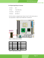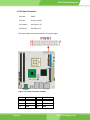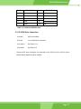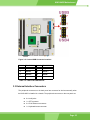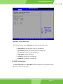
1
KINO-9452 Motherboard KINO-9452 Motherboard User Manual Page 1 KINO-9452 Motherboard REVISION HISTORY Title KINO-9452 Intel Core Duo/Core Solo Motherboard Revision Number Description Date of Issue 1.0 Initial release September 2006 COPYRIGHT NOTICE The information in this document is subject to change without prior notice in order to improve reliability, design and function and does not represent a commitment on the part of the manufacturer. In no event is the manufacturer liable for direct, indirect, special, incidental, or consequential damages arising out of the use or inability to use the product or documentation, even if advised of the possibility of such damages. This document contains proprietary information protected by copyright. All rights are reserved. No part of this manual may be reproduced by any mechanical, electronic, or other means in any form without prior written permission of the manufacturer. TRADEMARKS IBM PC is a registered trademark of International Business Machines Corporation. INTEL is a registered trademark of INTEL Corporation. AMI is registered trademarks of American Megatrends Inc. Other product names mentioned herein are used for identification purposes only and may be trademarks and/or registered trademarks of their respective owners. Page 2 KINO-9452 Motherboard Table of Contents 1 INTRODUCTION................................................................................................... 15 1.1 KINO-9452 OVERVIEW ........................................................................................... 16 1.1.1 KINO-9452 Benefits......................................................................................... 16 1.1.2 KINO-9452 Features........................................................................................ 16 1.2 KINO-9452 BOARD OVERVIEW............................................................................... 17 1.2.1 KINO-9452 Connectors ................................................................................... 17 1.2.2 Technical Specifications................................................................................... 18 2 DETAILED SPECIFICATIONS ........................................................................... 21 2.1 OVERVIEW ............................................................................................................... 22 2.2 DIMENSIONS ............................................................................................................ 22 2.2.1 Board Dimensions............................................................................................ 22 2.2.2 External Interface Panel Dimensions .............................................................. 23 2.3 CPU SUPPORT.......................................................................................................... 23 2.3.1 Intel® Core™ Duo ........................................................................................... 23 2.3.2 Intel® Core™ Solo ........................................................................................... 24 2.4 ON-BOARD CHIPSETS ............................................................................................... 25 2.4.1 Northbridge and Southbridge Chipsets ........................................................... 25 2.4.2 Intel 945GM Northbridge Chipset ................................................................... 25 2.4.3 Intel ICH7-M Southbridge Chipset.................................................................. 26 2.5 GRAPHICS SUPPORT ................................................................................................. 26 2.6 MEMORY SUPPORT ................................................................................................... 27 2.7 PCI BUS INTERFACE SUPPORT.................................................................................. 27 2.8 GBE ETHERNET ....................................................................................................... 27 2.9 DRIVE INTERFACES .................................................................................................. 28 2.9.1 SATA Drives ..................................................................................................... 28 2.9.2 IDE Interfaces.................................................................................................. 28 2.10 SERIAL PORTS ........................................................................................................ 29 2.11 REAL TIME CLOCK ................................................................................................. 29 2.12 USB INTERFACES................................................................................................... 29 2.13 BIOS ..................................................................................................................... 29 2.14 OPERATING TEMPERATURE AND TEMPERATURE CONTROL ..................................... 29 Page 3 KINO-9452 Motherboard 2.15 AUDIO CODEC ........................................................................................................ 30 2.16 POWER CONSUMPTION ........................................................................................... 31 2.17 PACKAGED CONTENTS AND OPTIONAL ACCESSORY ITEMS ..................................... 32 2.17.1 Package Contents........................................................................................... 32 2.17.2 Optional Accessory Items............................................................................... 32 3 CONNECTORS AND JUMPERS ......................................................................... 33 3.1 PERIPHERAL INTERFACE CONNECTORS .................................................................... 34 3.1.1 KINO-9452 Layout........................................................................................... 34 3.1.2 Peripheral Interface Connectors ..................................................................... 34 3.1.3 Rear Panel Connectors .................................................................................... 36 3.1.4 On-board Jumpers ........................................................................................... 36 3.2 INTERNAL PERIPHERAL CONNECTORS ...................................................................... 37 3.2.1 Fan Connectors................................................................................................ 37 3.2.2 Front Panel Audio Connector.......................................................................... 38 3.2.3 Front Panel Connector .................................................................................... 39 3.2.4 Digital Input/Output Connector....................................................................... 41 3.2.5 IDE Connector ................................................................................................. 42 3.2.6 LCD Backlight Connector................................................................................ 43 3.2.7 LVDS LCD connector ...................................................................................... 44 3.2.8 Mini PCI Slot ................................................................................................... 46 3.2.9 Power Connector ............................................................................................. 48 3.2.10 14-Pin Serial Port Connectors....................................................................... 49 3.2.11 10-Pin Serial Port Connectors....................................................................... 50 3.2.12 SATA Drive Connectors ................................................................................. 51 3.2.13 SPDIF Connector........................................................................................... 53 3.2.14 Internal USB Connectors............................................................................... 54 3.3 EXTERNAL INTERFACE CONNECTORS ....................................................................... 55 3.3.1 Audio Connectors............................................................................................. 56 3.3.2 CRT Connector ................................................................................................ 57 3.3.3 Ethernet Connectors ........................................................................................ 58 3.3.4 Keyboard/Mouse Connector ............................................................................ 59 3.3.5 Serial Port Connectors .................................................................................... 60 3.3.6 TV-Out Connector ............................................................................................ 61 3.3.7 USB Connector ................................................................................................ 62 4 INSTALLATION AND CONFIGURATION ....................................................... 63 Page 4 KINO-9452 Motherboard 4.1 ANTI-STATIC PRECAUTIONS ...................................................................................... 64 4.2 INSTALLATION CONSIDERATIONS ............................................................................. 64 4.2.1 Installation Notices .......................................................................................... 64 4.3 UNPACKING.............................................................................................................. 65 4.3.1 Unpacking Precautions.................................................................................... 65 4.3.2 Checklist........................................................................................................... 66 4.4 KINO-9452 MOTHERBOARD INSTALLATION ............................................................ 66 4.4.1 CPU Installation .............................................................................................. 67 4.4.2 Cooling Kit (CF-479B-RS ) Installation .......................................................... 69 4.4.3 DIMM Module Installation .............................................................................. 71 4.4.3.1 Purchasing the Memory Module............................................................... 71 4.4.3.2 DIMM Module Installation....................................................................... 71 4.4.4 Peripheral Device Connection......................................................................... 73 4.4.4.1 IDE Disk Drive Connector (IDE1) ........................................................... 73 4.4.4.2 COM Port Connectors............................................................................... 74 4.5 ON-BOARD JUMPERS ................................................................................................ 75 4.5.1 Clear CMOS Jumper........................................................................................ 76 4.5.2 COM2 Mode Selection..................................................................................... 77 4.5.3 LVDS LCD Voltage Selection........................................................................... 78 4.6 CHASSIS INSTALLATION ........................................................................................... 78 4.7 REAR PANEL CONNECTORS ...................................................................................... 79 4.7.1 LCD Panel Connection .................................................................................... 79 4.7.2 Ethernet Connection ........................................................................................ 79 4.7.3 USB Connection............................................................................................... 79 4.7.4 Serial Connection............................................................................................. 79 4.7.5 Keyboard and Mouse Connection.................................................................... 79 4.7.6 Audio Interface................................................................................................. 79 5 AMI BIOS SETUP.................................................................................................. 81 5.1 INTRODUCTION ........................................................................................................ 82 5.1.1 Starting Setup................................................................................................... 82 5.1.2 Using Setup ...................................................................................................... 82 5.1.3 Getting Help..................................................................................................... 83 5.1.4 Unable to Reboot after Configuration Changes .............................................. 83 5.1.5 BIOS Menu Bar................................................................................................ 83 5.2 MAIN ....................................................................................................................... 83 Page 5 KINO-9452 Motherboard 5.3 ADVANCED ............................................................................................................... 85 5.3.1 CPU Configuration.......................................................................................... 86 5.3.2 IDE Configuration ........................................................................................... 87 5.3.2.1 IDE Master, IDE Slave ............................................................................. 89 5.3.3 Super IO Configuration.................................................................................... 93 5.3.4 Hardware Health Configuration...................................................................... 96 5.3.5 ACPI Configuration ......................................................................................... 98 5.3.5.1 General ACPI Configuration..................................................................... 99 5.3.6 APM Configuration........................................................................................ 100 5.3.7 MPS Configuration ........................................................................................ 102 5.3.8 Remote Access Configuration ........................................................................ 103 5.3.9 USB Configuration......................................................................................... 105 5.3.9.1 USB Mass Storage Device Configuration............................................... 107 5.4 PCI/PNP ................................................................................................................ 109 5.5 BOOT ......................................................................................................................115 5.5.1 Boot Settings Configuration............................................................................115 5.5.2 Boot Device Priority .......................................................................................118 5.5.3 Removable Drives ...........................................................................................119 5.6 SECURITY............................................................................................................... 120 5.7 CHIPSET ................................................................................................................. 122 5.7.1 North Bridge Configuration........................................................................... 122 5.7.1.1 Video Function Configuration ................................................................ 125 5.7.2 South Bridge Configuration........................................................................... 128 5.8 EXIT ....................................................................................................................... 129 6 SOFTWARE DRIVERS ....................................................................................... 131 6.1 AVAILABLE SOFTWARE DRIVERS ............................................................................ 132 6.2 CHIPSET DRIVER INSTALLATION............................................................................. 132 6.3 VGA DRIVER ......................................................................................................... 135 6.4 BROADCOM LAN DRIVER (FOR GBE LAN) INSTALLATION .................................. 139 6.5 REALTEK HD AUDIO DRIVER (ALC883) INSTALLATION ....................................... 143 6.6 INTEL MATRIX STORAGE MANAGER INSTALLATION ............................................... 147 A BIOS CONFIGURATION OPTIONS ................................................................ 151 A.1 BIOS CONFIGURATION OPTIONS........................................................................... 152 B WATCHDOG TIMER .......................................................................................... 156 Page 6 KINO-9452 Motherboard C ADDRESS MAPPING.......................................................................................... 160 C.1 IO ADDRESS MAP ................................................................................................. 161 C.2 1ST MB MEMORY ADDRESS MAP ......................................................................... 161 C.3 IRQ MAPPING TABLE ............................................................................................ 162 C.4 DMA CHANNEL ASSIGNMENTS ............................................................................. 162 D INDEX.................................................................................................................... 164 Page 7 KINO-9452 Motherboard List of Figures Figure 1-1: KINO-9452 Board Overview (Top View).................................................17 Figure 2-1: KINO-9452 Dimensions (mm) .................................................................22 Figure 2-2: External Interface Panel Dimensions (mm)...........................................23 Figure 3-1: Connector and Jumper Locations .........................................................34 Figure 3-2: Fan Connector Locations .......................................................................37 Figure 3-3: Front Panel Audio Connector Location.................................................38 Figure 3-4: Front Panel Connector Location............................................................40 Figure 3-5: GPIO Connector Location.......................................................................41 Figure 3-6: IDE Device Connector Location .............................................................42 Figure 3-7: LCD Backlight Connector Location .......................................................44 Figure 3-8: LVDS LCD Connector Location..............................................................45 Figure 3-9: Mini PCI Slot Location.............................................................................46 Figure 3-10: Power Connector Location ...................................................................48 Figure 3-11: 14-Pin Serial Port Connector Locations..............................................49 Figure 3-12: 10-Pin Serial Port Connector Locations..............................................50 Figure 3-13: SATA Drive Connector Locations........................................................52 Figure 3-14: SPDIF Connector Locations .................................................................53 Figure 3-15: Internal USB Connector Locations ......................................................55 Figure 3-16: KINO-9452 External Interface Connectors ..........................................56 Figure 3-17: Audio Connectors..................................................................................57 Figure 3-18: VGA Connector ......................................................................................57 Figure 3-19: RJ-45 Ethernet Connector ....................................................................58 Figure 3-20: PS/2 Pinouts...........................................................................................59 Figure 3-21: External Serial Port Connector ............................................................60 Figure 3-22: TV-Out Connector..................................................................................61 Figure 4-1: Make sure the CPU socket retention screw is unlocked .....................68 Figure 4-2: Lock the CPU Socket Retention Screw .................................................69 Figure 4-3: IEI CF-479B-RS Cooling Kit ....................................................................69 Figure 4-4: Securing the Cooling Kit.........................................................................70 Page 8 KINO-9452 Motherboard Figure 4-5: Connect the cooling fan cable ...............................................................71 Figure 4-6: Installing the DIMM Module ....................................................................72 Figure 4-7: Locking the DIMM Module ......................................................................72 Figure 4-8: Connection of IDE Connector ................................................................74 Figure 4-9 Jumper ....................................................................................................75 Figure 4-10: Jumper Locations..................................................................................76 Figure 6-1: InstallShield Wizard Preparation Screen............................................ 133 Figure 6-2: Welcome Screen ................................................................................... 133 Figure 6-3: License Agreement............................................................................... 134 Figure 6-4: Readme Information ............................................................................. 134 Figure 6-5: Restart the Computer ........................................................................... 135 Figure 6-6: Starting Install Shield Wizard Screen ................................................. 136 Figure 6-7: Preparing Setup Screen ....................................................................... 136 Figure 6-8: VGA Driver Installation Welcome Screen........................................... 137 Figure 6-9: VGA Driver License Agreement .......................................................... 137 Figure 6-10: VGA Driver Installing Notice.............................................................. 138 Figure 6-11: VGA Driver Installation Complete ..................................................... 138 Figure 6-12: Access Windows Control Panel........................................................ 139 Figure 6-13: Double Click the System Icon ........................................................... 140 Figure 6-14: Double Click the Device Manager Tab.............................................. 140 Figure 6-15: Device Manager List ........................................................................... 141 Figure 6-16: Search for Suitable Driver.................................................................. 141 Figure 6-17: Locate Driver Files.............................................................................. 142 Figure 6-18: Location Browsing Window............................................................... 142 Figure 6-19: Access Windows Control Panel........................................................ 143 Figure 6-20: Double Click the System Icon ........................................................... 144 Figure 6-21: Double Click the Device Manager Tab.............................................. 144 Figure 6-22: Device Manager List ........................................................................... 145 Figure 6-23: Search for Suitable Driver.................................................................. 146 Figure 6-24: Locate Driver Files.............................................................................. 147 Figure 6-25: Preparing Setup Screen ..................................................................... 148 Page 9 KINO-9452 Motherboard List of Tables Table 1-1: Technical Specifications ..........................................................................20 Table-2-1: Supported CPUs........................................................................................23 Table 2-2: Power Consumption .................................................................................31 Table 3-1: Peripheral Interface Connectors..............................................................35 Table 3-2: Rear Panel Connectors.............................................................................36 Table 3-3: On-board Jumpers ....................................................................................36 Table 3-4: Fan Connector Pinouts.............................................................................38 Table 3-5: Front Panel Audio Connector Pinouts ....................................................39 Table 3-6: Front Panel Connector Pinouts ...............................................................40 Table 3-7: GPIO Connector Pinouts ..........................................................................41 Table 3-8: IDE Connector Pinouts .............................................................................43 Table 3-9: LCD Backlight Connector Pinouts ..........................................................44 Table 3-10: LVDS LCD Connector Pinouts ...............................................................46 Table 3-11: Mini PCI Slot Pinouts ..............................................................................47 Table 3-12: Power Connector Pinouts ......................................................................49 Table 3-13: COM2 Pinouts..........................................................................................50 Table 3-14: COM3 and COM4 Pinouts .......................................................................51 Table 3-15: SATA Drive Connector Pinouts .............................................................52 Table 3-16: SPDIF Pinouts..........................................................................................54 Table 3-17: USB3 and USB4 Pinouts.........................................................................55 Table 3-18: VGA Connector Pinouts .........................................................................58 Table 3-19: LAN1 and LAN2 Pinouts .........................................................................58 Table 3-20: RJ-45 Ethernet Connector LEDs............................................................59 Table 3-21: PS/2 Connector Pinouts .........................................................................60 Table 3-22: External Serial Port Pinouts ...................................................................61 Table 3-23: TV-Out Pinouts ........................................................................................62 Table 3-24: External USB Connector Pinouts ..........................................................62 Table 4-1: IEI Provided Cables...................................................................................73 Table 4-2: On-board Jumpers ....................................................................................75 Page 10 KINO-9452 Motherboard Table 4-3: Clear CMOS Jumper Settings ..................................................................77 Table 4-4: JP1 Jumper Settings.................................................................................77 Table 4-5: JP2 Jumper Settings.................................................................................78 Table 5-1: BIOS Navigation Keys...............................................................................83 Page 11 KINO-9452 Motherboard List of BIOS Menus BIOS Menu 1: Main ....................................................................................................84 BIOS Menu 2: Advanced.............................................................................................86 BIOS Menu 3: CPU Configuration..............................................................................87 BIOS Menu 4: IDE Configuration ...............................................................................88 BIOS Menu 5: IDE Master and IDE Slave Configuration..........................................90 BIOS Menu 6: Super IO Configuration ......................................................................93 BIOS Menu 7: Hardware Health Configuration.........................................................96 BIOS Menu 8: ACPI Configuration.............................................................................98 BIOS Menu 9: General ACPI Configuration [Advanced\ ACPI Configuration] ......99 BIOS Menu 10: APM Configuration ........................................................................ 100 BIOS Menu 11: MPS Configuration ........................................................................ 103 BIOS Menu 12: Remote Access Configuration [Advanced] ................................ 104 BIOS Menu 13: USB Configuration......................................................................... 105 BIOS Menu 14: USB Mass Storage Device Configuration.................................... 108 BIOS Menu 15: PCI/PnP Configuration .................................................................. 110 BIOS Menu 16: Boot................................................................................................. 115 BIOS Menu 17: Boot Settings Configuration......................................................... 116 BIOS Menu 18: Boot Device Priority Settings ....................................................... 119 BIOS Menu 19: Removable Drives.......................................................................... 120 BIOS Menu 20: Security........................................................................................... 121 BIOS Menu 21: Chipset............................................................................................ 122 BIOS Menu 22: North Bridge Chipset Configuration............................................ 123 BIOS Menu 23:South Bridge Chipset Configuration ............................................ 128 BIOS Menu 24:Exit ................................................................................................. 129 Page 12 KINO-9452 Motherboard Glossary AC ’97 Audio Codec 97 HDD Hard Disk Drive ACPI Advanced Configuration and IDE Integrated Data Electronics Power Interface I/O Input/Output APM Advanced Power Management ICH4 I/O Controller Hub 4 ARMD ATAPI Removable Media Device L1 Cache Level 1 Cache ASKIR Shift Keyed Infrared L2 Cache Level 2 Cache ATA Advanced Technology LCD Liquid Crystal Display Attachments LPT Parallel Port Connector BIOS Basic Input/Output System LVDS Low Voltage Differential Signaling CFII Compact Flash Type 2 MAC Media Access Controller CMOS Complementary Metal Oxide OS Operating System Semiconductor PCI Peripheral Connect Interface CPU Central Processing Unit PIO Programmed Input Output Codec Compressor/Decompressor PnP Plug and Play COM Serial Port POST Power On Self Test DAC Digital to Analog Converter RAM Random Access Memory DDR Double Data Rate SATA Serial ATA DIMM Dual Inline Memory Module S.M.A.R.T Self Monitoring Analysis and DIO Digital Input/Output DMA Direct Memory Access SPD Serial Presence Detect EIDE Enhanced IDE S/PDI Sony/Philips Digital Interface EIST Enhanced Intel SpeedStep SDRAM Synchronous Dynamic Random Reporting Technology Access Memory Technology FDD Floppy Disk Drive SIR Serial Infrared FDC Floppy Disk Connector UART Universal Asynchronous FFIO Flexible File Input/Output FIFO First In/First Out USB Universal Serial Bus FSB Front Side Bus VGA Video Graphics Adapter IrDA Infrared Data Association Receiver-transmitter Page 13 KINO-9452 Motherboard THIS PAGE IS INTENTIONALLY LEFT BLANK Page 14 IEI® Technology, Corp. KINO-9452 Motherboard Chapter 1 1 Introduction Page 15 KINO-9452 Motherboard 1.1 KINO-9452 Overview The Mini-ITX form factor KINO-9452 with Intel® Core™2 Duo / Core™ Solo CPU platform is fully equipped with latest technology and advanced multi-mode I/Os. The KINO-9452 is designed for system manufacturers, integrators, and VARs that want performance, reliability, and quality at a reasonable price. 1.1.1 KINO-9452 Benefits Some of the KINO-9452 benefits include: Dual-core Intel® processor support o o Two physical cores in a package share the system load Each core has its own L1 cache and shares the L2 cache to enhance the processing speed o High performance levels especially in 3D graphic and multi media application Independent dual audio with HDTV output Excellent thermal control that enhance voltage efficiency and supports cooler and quieter systems Mini PCI expansion slot and rich I/O interface o o Integrates a PCI and a mini PCI slot for flexible expansion capabilities Integrates TV-out and multi channel audio for related applications DDR2 memory technology supported SATA II with 3.0Gb/s transfer rate Dual PCIe GbE enhance high performance in network 1.1.2 KINO-9452 Features Some of the KINO-9452 features are listed below: Complies with RoHS Supports Intel® Core™2 Duo, Core™ Duo and Core™ Solo processor Supports a maximum front side bus (FSB) speed up to 667MHz Supports up to 2GB of 400MHz, 533MHz or 667MHz of DDR2 memory Comes with dual Broadcom BCM5787 for PCIe GbE Supports two SATA II channels with transfer rates up to 3.0Gb/s Page 16 IEI® Technology, Corp. KINO-9452 Motherboard Supports eight USB 2.0 devices Supports HDTV-Out, dual 18 channel LVDS and CRT 1.2 KINO-9452 Board Overview Figure 1-1: KINO-9452 Board Overview (Top View) 1.2.1 KINO-9452 Connectors The KINO-9452 has the following connectors on-board: 2 x DDR2 DIMM sockets 1 x Digital I/O connector 3 x Fan connectors 1 x Front panel audio connector 1 x Front panel connector Page 17 KINO-9452 Motherboard 1 x IDE Interface connector 1 x LCD backlight connector 1 x LVDS LCD connector 1 x Mini PCI slot 1 x PCI slot 1 x Power connector 3 x Serial port connectors 2 x SATA II connectors 1 x SPDIF connector 2 x USB connectors The KINO-9452 has the following connectors on the board rear panel: 6 x Audio jacks 1 x CRT connector 2 x Ethernet connectors 1 x Keyboard/Mouse connector 1 x Serial port connector 1 x TV-Out port 4 x USB 2.0 ports The KINO-9452 has the following on-board jumpers: Clear CMOS COM2 mode selection (RS-232/422/485) LVDS LCD voltage selection The location of these connectors on the motherboard can be seen in Figure 1-1. These connectors are fully described in Chapter 3. 1.2.2 Technical Specifications KINO-9452 technical specifications are listed in Table 1-1. Detailed descriptions of each specification can be found in Chapter 2 Detailed Specifications. Page 18 IEI® Technology, Corp. KINO-9452 Motherboard SPECIFICATION CPUs Supported Intel® Core™2 Duo/ Core™ Duo/Core™ Solo with 533/667MHz FSB Chipsets Northbridge: Intel 945GM Southbridge: ICH7-M I/O Controller ICH7-M Graphics Support Intel Gen 3.5 Integrated Graphics Engine Display CRT HDTV: MacroVision support / Overscaling / Component, S-Video and Composite output 480P / 720P / 1080i / 1080P and NTSC / PAL support LVDS: Dual channel 18-bit LVDS Memory Dual channel DDR2 400/533/667MHz memory modules (Max. 2GB) PCI Bus Interface 33MHz, Revision 2.3 Serial ATA (SATA) Two SATA II connectors with 3.0Gb/s transfer rates HDD Interface One IDE channel support two Ultra ATA 100 devices USB Interfaces Eight USB 2.0 connectors supported Serial Ports Four COM ports Extension One Mini PCI slot One PCI slot Super I/O ITE8712 Digital I/O 8 bit digital I/O, 4 input / 4 output by super I/O Audio REALTEK ALC883 with 7.1 channel HD interface with 2 audio streams support Page 19 KINO-9452 Motherboard Ethernet Dual Broadcom BCM5787 for PCI Express GbE with ASF2.0 remote control support BIOS AMI BIOS Label Power ATX power Physical Dimensions 170mm x 170mm (width x length) Operating Minimum: 0ºC (32°F) Temperature Maximum: 60°C (140°F) Table 1-1: Technical Specifications Page 20 IEI® Technology, Corp. KINO-9452 Motherboard Chapter 2 2 Detailed Specifications Page 21 KINO-9452 Motherboard 2.1 Overview This chapter describes the specifications and on-board features of the KINO-9452 in detail. 2.2 Dimensions 2.2.1 Board Dimensions The dimensions of the board are shown in Figure 2-1. Figure 2-1: KINO-9452 Dimensions (mm) Page 22 IEI® Technology, Corp. KINO-9452 Motherboard 2.2.2 External Interface Panel Dimensions External interface panel dimensions are shown in Figure 2-2. Figure 2-2: External Interface Panel Dimensions (mm) 2.3 CPU Support Table-2-1 lists the CPUs supported by the KINO-9452 board. Model Clock Speed L2 Cache Max. FSB Socket Intel® Core™2 Duo 1.66 to 2.33 GHz 2MB/4MB 667 MHz 479 Intel® Core™ Duo 1.20 to 2.33 GHz 2 MB 667 MHz 479 Intel® Core™ Solo 1.06 to 1.83 GHz 2 MB 667 MHz 479 Table-2-1: Supported CPUs 2.3.1 Intel® Core™2 Duo The Intel® Core™2 Duo processor comes with the following features: Dual core processor with enhanced performance Intel® 64 architecture Supports Intel Architecture with Dynamic Execution On-die, primary 32-kB instruction cache and 32-kB write-back data cache per core On-die, up to 4-MB second level shared cache with Advanced Transfer Cache Architecture Data Prefetch Logic Page 23 KINO-9452 Motherboard 667-MHz, Source-Synchronous FSB for Standard Voltage processors Advanced Power Management features including Enhanced Intel SpeedStep® Technology Intel Enhanced Deeper Sleep state and Dynamic Cache Sizing 2.3.2 Intel® Core™ Duo The Intel® Core™ Duo processor comes with the following features: Two complete execution cores in one processor package provide advancements in simultaneous computing Dual-core processing efficiently delivers performance while balancing power requirements Two execution cores share a high-performance, power-optimized 667 MHz front-side bus (FSB) to access the same chipset memory. Enhanced Intel SpeedStep® technology allows a system to dynamically adjust processor voltage and core frequency, decreasing average power consumption and average heat production Intel® Smart Cache Design allows two execution cores to share 2 MB of L2 cache, reducing FSB traffic and enhancing system responsiveness Intel® Advanced Thermal Manager supports new digital temperature sensors and thermal monitors on each execution core to enhance thermal monitoring accuracy Streaming SIMD Extensions 3 (SSE3) provides significant performance enhancement for multi-media applications Embedded lifecycle support protects system investment by enabling extended product availability for embedded and communications customers 2.3.3 Intel® Core™ Solo The Intel® Core™ Solo processor comes with the following features: Supports Intel Architecture with Dynamic Execution On-die, primary 32-KB instruction cache and 32-KB write-back data cache On-die, 2-MB second level cache with Advanced Transfer Cache Architecture Streaming SIMD Extensions 2 (SSE2) and Streaming SIMD Extensions 3 (SSE3) Page 24 IEI® Technology, Corp. KINO-9452 Motherboard Advanced power management features including Enhanced Intel SpeedStep® technology Execute Disable Bit support for enhanced security Intel Virtualization Technology enhances virtualization robustness and performance 2.4 On-board Chipsets 2.4.1 Northbridge and Southbridge Chipsets The following chipsets are preinstalled on the board: Northbridge: Intel® 945GM Southbridge: Intel® ICH7-M The following two sections (Section 2.4.2 and Section 2.4.3) list some of the features of the Intel 945GM and the Intel ICH7-M chipsets. For more information on these two chipsets please refer to the Intel website. 2.4.2 Intel 945GM Northbridge Chipset The Intel 945GM northbridge chipset comes with the following features: System Memory Support o o o o o Supports single/dual-channel DDR2 SDRAM 64-bit wide per channel 256-MB, 512-MB and 1-Gb memory technologies supported Support for DDR2 On-Die Termination (ODT) Support for 2N timings only Internal Graphics o o Intel Gen 3.5 Integrated Graphics Engine 250 MHz core render clock and 200 MHz core display clock at 1.05 V core voltage o Supports TV-Out, LVDS, CRT and SDVO DMI o o o Chip-to-chip interface between (G)MCH and ICH Configurable as x2 or x4 DMI lanes DMI lane reversal support Page 25 KINO-9452 Motherboard o 32-bit downstream address Power Management o o o ACPI S0, S3, S4, S5 CPU States C0, C1, C2, C3, C4 states Rapid Memory Power Mgmt 2.4.3 Intel ICH7-M Southbridge Chipset The Intel ICH7-M southbridge chipset comes with the following features: PCI Local Bus Specification, Revision 2.3 support for 33 MHz PCI operations (supports up to six Req/Gnt pairs) ACPI Power Management Logic support Enhanced DMA controller, interrupt controller, and timer functions Integrated Serial ATA host controller with independent DMA operation on two ports and AHCI Integrated IDE controller supports Ultra ATA 100/66/33 USB host interface with support for eight USB ports; four UHCI host controller; one EHCI high-speed USB 2.0 Host controller Supports Audio Codec ’97, Revision 2.3 Specification Supports Intel High Definition Audio Supports Intel Matrix Storage Technology Supports Intel Active Management Technology Low Pint Count (LPC) interface Firmware Hub (FWH) interface support Serial Peripheral Interface (SPI) support 2.5 Graphics Support The graphics features listed below are all integrated on the Intel 945GM northbridge chipset. Analog CRT o o o Integrated 400 MHz RAMDAC Analog monitor support up to QXGA Support for CRT hot plug LVDS Page 26 IEI® Technology, Corp. KINO-9452 Motherboard o o Panel support up to UXGA (1600 x 1200) 25 MHz – 112 MHz single-/dual-channel; @18bpp – TFT panel type supported o o o o o o Pixel Dithering for 18-bit TFT panel to emulate 24-bpp true color displays Panel Fitting. Panning, and Center Mode supported CPIS 1.5 compliant Spread spectrum clocking supported Panel Power Sequencing support Integrated PWM interface for LCD backlight inverter control TV-Out o o o o o o Three integrated 10-bit DACS MacroVision support Overscaling NTSC/PAL Component, S-Video and Composite Output interfaces HDTV support – 480p/720p/1080i/1080p SDVO Ports o o o Concurrent operation of x1 PCIe with SDVO Two SDVO ports supported Supports appropriate external SDVO components (DVI, LVDS, TV-Out) 2.6 Memory Support The KINO-9452 has two DDR2 DIMM sockets and supports two 400MHz, 533MHz or 667MHz DDR2 DIMM with a maximum RAM of up to 2GB. 2.7 PCI Bus Interface Support The PCI bus on the KINO-9452 has the following features: 33MHz Revision 2.3 is implemented Six PCI REQ/GNT pairs is available 64-bit addressing on PCI using DAC protocol is supported 2.8 GbE Ethernet The BCM5787 is a seventh generation 10/100/1000BASE-T Ethernet LAN controller solution for high performance network applications. The device combines a triple-speed Page 27 KINO-9452 Motherboard IEEE 802.3 compliant Media Access Controller (MAC) with a triple-speed Ethernet transceiver, PCIe bus interface, and on-chip buffer memory in a single device. The device is fabricated in a 1.2V CMOS process providing a low-power system solution. The GbE controller features are below. Integrated 10/100/1000 transceiver 10/100/1000 full/half-duplex MAC Automatic MDI crossover function Supports PCIe v1.0a Wake-on-LAN support meeting the ACPI requirements Statistics for SNMP MIB II, Ethernet-like MIB and Ethernet MIB (802.3z, clause 30) Serial EEPROM or serial flash supported JTAG supported 196-FBGA package 2.9 Drive Interfaces The KINO-9452 can support the following drive interfaces. 2 x SATA drives 2 x IDE devices 2.9.1 SATA Drives The KINO-9452 supports two SATA II drives with transfer rates of up to 3.0Gb/s. 2.9.2 IDE Interfaces The KINO-9452 southbridge chipset IDE controller supports up to two IDE devices with the following specifications: Supports PIO IDE transfers up to 16MB/s Supports Ultra ATA 100 devices with data transfer rates up to 100MB/s Page 28 IEI® Technology, Corp. KINO-9452 Motherboard 2.10 Serial Ports The KINO-9452 has four high-speed UART serial ports, configured as COM1, COM2, COM3 and COM4. The serial ports have the following specifications. 16C550 UART with 16-byte FIFO buffer 115.2Kbps transmission rate 2.11 Real Time Clock 256-byte battery backed CMOS SRAM 2.12 USB Interfaces The KINO-9452 supports eight USB interfaces, four internal and four external. The USB interfaces support USB 2.0. 2.13 BIOS The KINO-9452 uses a licensed copy of AMI BIOS. The features of the flash BIOS used are listed below: SMIBIOS (DMI) compliant Console redirection function support PXE (Pre-Boot Execution Environment ) support USB booting support 2.14 Operating Temperature and Temperature Control The maximum and minimum operating temperatures for the KINO-9452 are listed below. Minimum Operating Temperature: 0ºC (32°F) Maximum Operating Temperature: 60°C (140°F) A cooling fan and heat sink must be installed on the CPU. Thermal paste must be smeared on the lower side of the heat sink before it is mounted on the CPU. Heat sinks are also mounted on the northbridge and southbridge chipsets to ensure the operating temperature of these chips remain low. Page 29 KINO-9452 Motherboard 2.15 Audio Codec The KINO-9452 has an integrated REALTEK ALC883 CODEC. The ALC883 CODEC is a Value 7.1+2 Channel High Definition Audio (HDA) codecs. The ALC883 series provide 10 DAC channels that simultaneously support 7.1 sound playback, plus 2 channels of independent stereo sound output (multiple streaming) through the front panel stereo output. Some of the features of the codec are listed below. High-performance DACs with 95dB SNR (A-Weighting), ADCs with 85dB SNR (A-Weighting) Meets performance requirements for audio on PC2001 systems and Microsoft WLP 2.x Ten DAC channels support 16/20/24-bit PCM format for 7.1 sound playback, plus 2 channels of independent stereo sound output (multiple streaming) through the front panel output 2 stereo ADCs support 16/20/24-bit PCM format, one for stereo microphone, the other for legacy mixer recording All DACs support 44.1k/48k/96k/192kHz sample rate All ADCs support 44.1k/48k/96kHz sample rate 16/20/24-bit S/PDIF-OUT supports 44.1k/48k/96k/192kHz sample rate 16/20/24-bit S/PDIF-IN supports 44.1k/48k/96kHz sample rate Up to four channels of microphone array input are supported for AEC/BF application High-quality analog differential CD input Supports external PCBEEP input and built-in digital BEEP generator Software selectable 2.5V/3.75V VREFOUT Two jack detection pins, each designed to detect up to 4 jacks Reserve analog mixer architecture for backward compatibility with AC'97 Wide range (–80dB ~ +42dB) volume control with 1.5dB resolution of analog to analog mixer gain All analog jacks are stereo input and output re-tasking for analog plug & play Built-in headphone amplifiers for each re-tasking jack 2 GPIOs (General Purpose Input/Output) for customized applications Power support: Digital: 3.3V; Analog: 3.0V~5.0V (Minimum AVDD is 3.0V) Pin compatible with the ALC880 and ALC882 Enhanced S/PDIF-IN circuitry ensures compatibility with consumer DVD Page 30 IEI® Technology, Corp. KINO-9452 Motherboard players 48-pin LQFP 'Green' package Meets Microsoft WHQL/WLP 2.x audio requirements EAX™ 1.0 & 2.0 compatible Direct Sound 3D™ compatible A3D™ compatible I3DL2 compatible HRTF 3D Positional Audio Emulation of 26 sound environments to enhance gaming experience 10-Band Software Equalizer Voice Cancellation and Key Shifting in Karaoke mode Realtek Media Player Enhanced Configuration Panel to improve user experience Microphone Acoustic Echo Cancellation (AEC), Noise Suppression (NS), and Beam Forming (BF) technology for voice application ALC883D features optional Dolby® Digital Live output for consumer equipment ALC883DTS features optional DTS® Connect software 2.16 Power Consumption Table 2-2 shows the power consumption parameters for the KINO-9452 when an Intel Core Duo processor with a clock speed of 2.16GHz is running with two DDR2 1GB DIMM modules. Voltage Current +5V 1.58A +12V 2.05A +3.3V 3.12A 5VSB 0.32A Table 2-2: Power Consumption Page 31 KINO-9452 Motherboard 2.17 Packaged Contents and Optional Accessory Items 2.17.1 Package Contents The KINO-9452 is shipped with the following components. 1 x KINO-9452 single board computer 1 x IDE flat cable 2 x SATA cables 1 x SATA power cable 2 x RS-232 cables 1 x HDTV out cable 1 x I/O shielding 1 x Mini jumper pack 1 x Utility CD 1 x Quick Installation Guide 2.17.2 Optional Accessory Items The items shown in the list below are optional accessory items are purchased separately. CPU cooler USB cable RS-232/422/485 cable Page 32 IEI® Technology, Corp. KINO-9452 Motherboard Chapter 3 3 Connectors and Jumpers Page 33 KINO-9452 Motherboard 3.1 Peripheral Interface Connectors Section 3.1.1 shows peripheral interface connector locations. Section 3.1.2 lists all the peripheral interface connectors seen in Section 3.1.1. 3.1.1 KINO-9452 Layout Figure 3-1 shows the on-board peripheral connectors, backplane peripheral connectors and on-board jumpers. Figure 3-1: Connector and Jumper Locations 3.1.2 Peripheral Interface Connectors Table 3-1 shows a list of the peripheral interface connectors on the KINO-9452. Detailed descriptions of these connectors can be found in Section 3.2. Page 34 IEI® Technology, Corp. KINO-9452 Motherboard Connector Type Label DDR2 DIMM socket 240-pin slot DIMM1 DDR2 DIMM socket 240-pin slot DIMM2 Fan connector (CPU) 3-pin header CPU_FAN1 Fan connector (System) 3-pin header SYS_FAN1 Fan connector (Northbridge) 3-pin header NB_FAN1 Front panel connector 14-pin header F_PANEL1 Front panel audio connector 10-pin header AUDIO2 Digital Input/Output connector 10-pin header DIO1 IDE Interface connector 40-pin header IDE1 LCD backlight connector 6-pin header CN1 LVDS LCD connector 30-pin header LVDS1 Mini PCI slot 124-pin Mini PCI Type III slot MINIPCI PCI slot 124-pin PCI slot PCI2 Power connector 20-pin connector PWR1 Serial port connector (1) 14-pin header COM2 Serial port connector (2) 10-pin header COM3 Serial port connector (3) 10-pin header COM4 SATA drive connector (1) 7-pin SATA connector SATA1 SATA drive connector (2) 7-pin SATA connector SATA2 SPDIF connector 5-pin header SPDIF1 USB connector (1) 8-pin header USB4 USB connector (2) 8-pin header USB5 Table 3-1: Peripheral Interface Connectors Page 35 KINO-9452 Motherboard 3.1.3 Rear Panel Connectors Table 3-2 lists the rear panel connectors on the KINO-9452. Detailed descriptions of these connectors can be found in Section 3.3. Connector Type Label Audio Jacks Audio connector AUDIO1 CRT connector 15-pin female connector CRT_COM1 Ethernet connector (1) RJ-45 connector LAN/USB1A Ethernet connector (2) RJ-45 connector LAN/USB2A Keyboard/Mouse connector 6-pin mini din connector KBMS1 Serial port connector DB-9 male connector CRT_COM1 TV-Out port 7-pin TV port TV USB 2.0 port (1) USB port connector LAN/USB1B USB 2.0 port (2) USB port connector LAN/USB2B Table 3-2: Rear Panel Connectors 3.1.4 On-board Jumpers Table 3-3 lists the on-board jumpers. Detailed descriptions of these jumpers can be found in Section 4.5. Description Label Type Clear CMOS JP3 3-pin header COM2 mode selection JP1 3-pin header LVDS LCD voltage selection JP2 6-pin header Table 3-3: On-board Jumpers Page 36 IEI® Technology, Corp. KINO-9452 Motherboard 3.2 Internal Peripheral Connectors Internal peripheral connectors are found on the motherboard and are only accessible when the motherboard is outside of the chassis. This section has complete descriptions of all the internal, peripheral connectors on the KINO-9452. 3.2.1 Fan Connectors CN Label: CPU_FAN1, SYS_FAN1 and NB_FAN1 CN Type: 3-pin header CN Location: See Figure 3-2 CN Pinouts: See Table 3-4 The cooling fan connectors on the KINO-9452 provide a 12V, 500mA current to one CPU cooling fan, one system cooling fan and one Northbridge cooling fan. There is a “sense” pin in the fan connector, which transfers the fan’s sense signal to the system BIOS in order to recognize the fan speed. Please note that only some specific types of fans offer a rotation signal. Figure 3-2: Fan Connector Locations Page 37 KINO-9452 Motherboard PIN NO. DESCRIPTION 1 GND 2 +12V 3 Sense Table 3-4: Fan Connector Pinouts 3.2.2 Front Panel Audio Connector CN Label: AUDIO2 CN Type: 10-pin header (2x5) CN Location: See Figure 3-3 CN Pinouts: See Table 3-5 The front panel audio connector connect the on-board sound system of the KINO-9452 to the audio line out and microphone jacks on the front of the computer chassis. Figure 3-3: Front Panel Audio Connector Location Page 38 IEI® Technology, Corp. KINO-9452 Motherboard PIN NO. DESCRIPTION PIN NO. DESCRIPTION 1. Port1_L 2. GND 3. Port1_R 4. PRESENCE 5. Port2_R 6. SENSE1_RETUR 7. SENSE_SEND 8. (KEY) 9. Port2_L 10. SENSE2_RETUR Table 3-5: Front Panel Audio Connector Pinouts 3.2.3 Front Panel Connector CN Label: F_PANEL1 CN Type: 14-pin header (2x7) CN Location: See Figure 3-4 CN Pinouts: See Table 3-6 The front panel connector connects to several external switches and indicators to monitor and control the motherboard. These indicators and switches include: Power Power button Reset button Speaker HDD Page 39 KINO-9452 Motherboard Figure 3-4: Front Panel Connector Location PIN NO. DESCRIPTION PIN NO. DESCRIPTION 1 Power LED+ 2 Speaker+ 3 NC 4 NC 5 Power LED- 6 NC 7 Power Button# 8 Speaker- 9 Power Button 10 NC 11 IDE LED+ 12 Reset Button 13 IDE LED- 14 Reset Button# Table 3-6: Front Panel Connector Pinouts Page 40 IEI® Technology, Corp. KINO-9452 Motherboard 3.2.4 Digital Input/Output Connector CN Label: DIO1 CN Type: 10-pin header (2x6) CN Location: See Figure 3-5 CN Pinouts: See Table 3-7 The DIO connector is managed through a Super I/O chip. The DIO connector pins are user programmable. The digital IO port of KINO-9452 is 5V CMOS level. Figure 3-5: GPIO Connector Location PIN NO. DESCRIPTION PIN NO. DESCRIPTION 1 GND 2 +5V 3 INPUT0 4 OUTPUT0 5 INPUT1 6 OUTPUT1 7 INPUT2 8 OUTPUT2 9 INPUT3 10 OUTPUT3 Table 3-7: GPIO Connector Pinouts Page 41 KINO-9452 Motherboard 3.2.5 IDE Connector CN Label: IDE1 CN Type: 40-pin header (2x20) CN Location: See Figure 3-6 CN Pinouts: See Table 3-8 One primary 40-pin IDE device connector on the KINO-9452 motherboard supports connectivity to ATA 100 IDE devices with data transfer rates up to 100MB/s. Figure 3-6: IDE Device Connector Location PIN NO. Page 42 DESCRIPTION PIN NO. DESCRIPTION 1 RESET# 2 GND 3 DATA 7 4 DATA 8 5 DATA 6 6 DATA 9 7 DATA 5 8 DATA 10 9 DATA 4 10 DATA 11 11 DATA 3 12 DATA 12 13 DATA 2 14 DATA 13 IEI® Technology, Corp. KINO-9452 Motherboard PIN NO. DESCRIPTION PIN NO. DESCRIPTION 15 DATA 1 16 DATA 14 17 DATA 0 18 DATA 15 19 GND 20 (KEY) 21 DRQ 22 GND 23 IOW# 24 GND 25 IOR# 26 GND 27 CHRDY 28 GND 29 DACK 30 GND 31 INTERRUPT 32 N/C 33 SA1 34 P66DET 35 SA0 36 SA2 37 HDC CS0# 38 HDC CS1# 39 HDD ACTIVE# 40 GND Table 3-8: IDE Connector Pinouts 3.2.6 LCD Backlight Connector CN Label: CN1 CN Type: 6-pin header (1x6) CN Location: See Figure 3-7 CN Pinouts: See Table 3-9 The LCD backlight connector is for the LCD inverter connection. Page 43 KINO-9452 Motherboard Figure 3-7: LCD Backlight Connector Location PIN NO. DESCRIPTION 1 Back Light Power 2 Back Light Power 3 Back Light enable 4 NC 5 GND 6 GND Table 3-9: LCD Backlight Connector Pinouts 3.2.7 LVDS LCD connector CN Label: LVDS1 CN Type: 30-pin connector (2x15) Page 44 IEI® Technology, Corp. KINO-9452 Motherboard CN Location: See Figure 3-8 CN Pinouts: See Table 3-10 The connector supports one or two channel (18 or 36bit) LVDS panel. Figure 3-8: LVDS LCD Connector Location PIN NO. DESCRIPTION PIN NO. DESCRIPTION 1 GND 2 GND 3 1st LVDS data0 output + 4 1st LVDS data0 output - 5 1st LVDS data1 output + 6 1st LVDS data1 output - 7 1st LVDS data2 output + 8 1st LVDS data2 output - 9 1st LVDS clock output + 10 1st LVDS clock output - 11 NC 12 NC 13 GND 14 GND 15 2nd LVDS data0 output + 16 2nd LVDS data0 output - Page 45 KINO-9452 Motherboard PIN NO. DESCRIPTION PIN NO. DESCRIPTION 17 2nd LVDS data1 output + 18 2nd LVDS data1 output - 19 2nd LVDS data2 output + 20 2nd LVDS data2 output - 21 2nd LVDS clock output + 22 2nd LVDS clock output - 23 NC 24 NC 25 GND 26 GND 27 +LCD (3.3V, 5V or 12V) 28 +LCD (3.3V, 5V or 12V) 29 +LCD (3.3V, 5V or 12V) 30 +LCD (3.3V, 5V or 12V) Table 3-10: LVDS LCD Connector Pinouts 3.2.8 Mini PCI Slot CN Label: MINIPCI CN Type: 124-pin Mini PCI Type III slot CN Location: See Figure 3-9 CN Pinouts: See Table 3-11 Mini PCI is a small form factor version of a PCI card. Mini PCI expansion devices can be inserted into the Mini PCI slot. Figure 3-9: Mini PCI Slot Location Page 46 IEI® Technology, Corp. KINO-9452 Motherboard PIN NAME PIN NAME PIN NAME PIN NAME 1 TIP 32 GROUND 63 3.3V 94 AD[02] 2 RING 33 AD[31] 64 FRAME# 95 AD[03] 3 8PMJ-3 34 PME# 65 CLKRUN# 96 AD[00] 4 8PMJ-1 35 AD[29] 66 TRDY# 97 5V 5 8PMJ-6 36 RESERVED 67 SERR# 98 RESERVED_WIP5 6 8PMJ-2 37 GROUND 68 STOP# 99 AD[01] 7 8PMJ-7 38 AD[30] 69 GROUND 100 RESERVED_WIP5 8 8PMJ-4 39 AD[27] 70 3.3V 101 GROUND 9 8PMJ-8 40 3.3V 71 PERR# 102 GROUND 10 8PMJ-5 41 AD[25] 72 DEVSEL# 103 AC_SYNC 11 LED1_GRNP 42 AD[28] 73 C/BE[1]# 104 M66EN 12 LED2_YELP 43 RESERVED 74 GROUND 105 AC_SDATA_IN 13 LED1_GRNN 44 AD[26] 75 AD[14] 106 AC_SDATA_OUT 14 LED2_YELN 45 C/BE[3]# 76 AD[15] 107 AC_BIT_CLK 15 CHSGND 46 AD[24] 77 GROUND 108 AC_CODEC_ID0# 16 RESERVED 47 AD[23] 78 AD[13] 109 AC_CODEC_ID1# 17 INTB# 48 IDSEL 79 AD[12] 110 AC_RESET# 18 5V 49 GROUND 80 AD[11] 111 MOD_AUDIO_MON 19 3.3V 50 GROUND 81 AD[10] 112 RESERVED 20 INTA# 51 AD[21] 82 GROUND 113 AUDIO_GND 21 RESERVED 52 AD[22] 83 GROUND 114 GROUND 22 RESERVED 53 AD[19] 84 AD[09] 115 SYS_AUDIO_OUT 23 GROUND 54 AD[20] 85 AD[08] 116 SYS_AUDIO_IN 24 3.3VAUX 55 GROUND 86 C/BE[0]# 117 SYS_AUDIO_OUT GND 25 CLK 56 PAR 87 AD[07] 118 SYS_AUDIO_IN GND 26 RST# 57 AD[17] 88 3.3V 119 AUDIO_GND 27 GROUND 58 AD[18] 89 3.3V 120 AUDIO_GND 28 3.3V 59 C/BE[2]# 90 AD[06] 121 RESERVED 29 REQ# 60 AD[16] 91 AD[05] 122 MPCIACT# 30 GNT# 61 IRDY# 92 AD[04] 123 VCC5VA 31 3.3V 62 Ground 93 RESERVED 124 3.3VAUX Table 3-11: Mini PCI Slot Pinouts Page 47 KINO-9452 Motherboard 3.2.9 Power Connector CN Label: PWR1 CN Type: 20-pin connector CN Location: See Figure 3-10 CN Pinouts: See Table 3-12 This 20-pin power connector supports the ATX power supply. Figure 3-10: Power Connector Location PIN NO. DESCRIPTION PIN NO. DESCRIPTION Page 48 1 3.3V 11 3.3V 2 3.3V 12 -12V 3 GND 13 GND IEI® Technology, Corp. KINO-9452 Motherboard PIN NO. DESCRIPTION PIN NO. DESCRIPTION 4 +5V 14 PS_ON 5 GND 15 GND 6 +5V 16 GND 7 GND 17 GND 8 Power good 18 -5V 9 5VSB 19 +5V 10 +12V 20 +5V Table 3-12: Power Connector Pinouts 3.2.10 14-Pin Serial Port Connectors CN Label: COM2 CN Type: 14-pin header (2x7) CN Location: See Figure 3-11 CN Pinouts: See Table 3-13 The serial ports connectors connect to RS-232/422/485 serial port device. Figure 3-11: 14-Pin Serial Port Connector Locations Page 49 KINO-9452 Motherboard PIN NO. DESCRIPTION PIN NO. DESCRIPTION 1 DCD 2 DSR 3 RXD 4 RTS 5 TXD 6 CTS 7 DTR 8 RI 9 GND 10 NC 11 TX+ 12 TX- 13 RX+ 14 RX- Table 3-13: COM2 Pinouts 3.2.11 10-Pin Serial Port Connectors CN Label: COM3 and COM4 CN Type: 10-pin header (2x5) CN Location: See Figure 3-12 CN Pinouts: See Table 3-14 The serial ports connectors connect to RS-232 serial port device. Figure 3-12: 10-Pin Serial Port Connector Locations Page 50 IEI® Technology, Corp. KINO-9452 Motherboard PIN NO. DESCRIPTION PIN NO. DESCRIPTION 1 DCD 2 DSR 3 RXD 4 RTS 5 TXD 6 CTS 7 DTR 8 RI 9 GND 10 NC Table 3-14: COM3 and COM4 Pinouts 3.2.12 SATA Drive Connectors CN Label: SATA1 and SATA2 CN Type: 1x7 pin SATA drive connectors CN Location: See Figure 3-13 CN Pinouts: See Table 3-15 The two SATA drive connectors are connected to four SATA II drives. SATA II drives transfer data at speeds as high as 3.0Gb/s. Page 51 KINO-9452 Motherboard Figure 3-13: SATA Drive Connector Locations PIN NO. DESCRIPTION 1 GND 2 TXP 3 TXN 4 GND 5 RXN 6 RXP 7 GND Table 3-15: SATA Drive Connector Pinouts Page 52 IEI® Technology, Corp. KINO-9452 Motherboard 3.2.13 SPDIF Connector CN Label: SPDIF1 CN Type: 5-pin header (1x5) CN Location: See Figure 3-14 CN Pinouts: See Table 3-16 The SPDIF connector connects to the S/PDIF audio module, which bears S/PDIF digital output. S/PDIF (Sony/Philips Digital Interface) is a newest audio transfer file format, which allows the user to enjoy digital audio. The SPDIF1 port provides digital audio to external speaker or compressed AC3 data to an external Dolby Digital Decoder via a coaxial cable. Figure 3-14: SPDIF Connector Locations Page 53 KINO-9452 Motherboard PIN NO. DESCRIPTION 1 +5V 2 (KEY) 3 SPDIF_OUT 4 GND 5 SPDIF_IN Table 3-16: SPDIF Pinouts 3.2.14 Internal USB Connectors CN Label: USB4 and USB5 CN Type: 8-pin header (2x4) CN Location: See Figure 3-15 CN Pinouts: See Table 3-17 One 2x4 pin connector provides connectivity to two USB 2.0 ports. The USB ports are used for I/O bus expansion. Page 54 IEI® Technology, Corp. KINO-9452 Motherboard Figure 3-15: Internal USB Connector Locations PIN NO. DESCRIPTION PIN NO. DESCRIPTION 1 VCC 2 GND 3 DATA0- 4 DATA1+ 5 DATA0+ 6 DATA1- 7 GND 8 VCC Table 3-17: USB3 and USB4 Pinouts 3.3 External Interface Connectors The peripheral connectors on the back panel are connected to devices externally when the KINO-9452 is installed in a chassis. The peripheral connectors on the rear panel are: 6 x Audio jacks 1 x CRT connector 2 x RJ-45 Ethernet connectors 1 x Keyboard/mouse connector Page 55 KINO-9452 Motherboard 1 x Serial port connector 1 x TV-Out connector 4 x USB 2.0 connectors Figure 3-16: KINO-9452 External Interface Connectors 3.3.1 Audio Connectors CN Label: AUDIO1 CN Type: Audio jack CN Location: See Figure 3-16 (labeled number 7) CN Pinouts: See Figure 3-17 Center/Subwoofer port (Yellow): Connects the center/subwoofer speakers. Line In port (Light Blue): Connects a CD-ROM, DVD player, or other audio devices. Rear Speaker Out port (Black): Connects the rear speakers in a 4/6/8-channel audio configuration. Line Out port (Lime): Connects a headphone or a speaker. In 4,6,8-channel configuration, the function of this port becomes Front Speaker Out. Side Speaker Out port (Gray): Connectors the side speakers in an 8-channel audio configuration. Page 56 IEI® Technology, Corp. KINO-9452 Motherboard Microphone (Pink): Connects a microphone. Figure 3-17: Audio Connectors 3.3.2 CRT Connector CN Label: CRT_COM1 CN Type: 15-pin female connector CN Location: See Figure 3-16 (labeled number 9) CN Pinouts: See Table 3-18 The standard 15-pin VGA connector connects to a CRT or LCD display monitor. Figure 3-18: VGA Connector PIN NO. DESCRIPTION PIN NO. DESCRIPTION 1 RED 2 GREEN 3 BLUE 4 N/C 5 GND 6 GND 7 GND 8 GND 9 VCC 10 GND Page 57 KINO-9452 Motherboard 11 N/C 12 DDC DAT 13 HSYNC 14 VSYNC 15 DDC CLK Table 3-18: VGA Connector Pinouts 3.3.3 Ethernet Connectors CN Label: LAN/USB1A and LAN/USB2A CN Type: RJ-45 CN Location: See Figure 3-16 (labeled number 4 and 6) CN Pinouts: See Table 3-19 The KINO-9452 is equipped with two built-in GbE Ethernet controllers. The controllers can connect to the LAN through two RJ-45 LAN connectors. There are two LEDs on the connector indicating the status of LAN. The pin assignments are listed in the following table: PIN DESCRIPTION PIN DESCRIPTION 1 MDX0+ 5 MDX2- 2 MDX0- 6 MDX1- 3 MDX1+ 7 MDX3+ 4 MDX2+ 8 MDX3- Table 3-19: LAN1 and LAN2 Pinouts Figure 3-19: RJ-45 Ethernet Connector Page 58 IEI® Technology, Corp. KINO-9452 Motherboard The RJ-45 Ethernet connector has two status LEDs, one green and one yellow. The green LED indicates activity on the port and the yellow LED indicates the port is linked. See Table 3-20. SPEED LED STATUS DESCRIPTION ACT/LINK LED STATUS DESCRIPTION OFF 10Mbps connection OFF No link ORANGE 100Mbps connection YELLOW Linked GREEN 1Gbps connection BLINKING Data Activity Table 3-20: RJ-45 Ethernet Connector LEDs 3.3.4 Keyboard/Mouse Connector CN Label: KBMS1 CN Type: PS/2 connector CN Location: See Figure 3-16 (labeled number 1) CN Pinouts: See Table 3-21 The KINO-9452 keyboard and mouse connectors are standard PS/2 connectors. Figure 3-20: PS/2 Pinouts Page 59 KINO-9452 Motherboard PIN DESCRIPTION PIN DESCRIPTION 1 L_KDAT 7 L_MDAT 2 NC 8 NC 3 GND 9 GND 4 5V 10 5V 5 L_KCLK 11 L_MCLK 6 NC 12 NC Table 3-21: PS/2 Connector Pinouts 3.3.5 Serial Port Connectors CN Label: CRT_COM1 CN Type: DB-9 CN Location: See Figure 3-16 (labeled number 2) CN Pinouts: See Table 3-22 The serial ports can be connected to a serial communications device directly. Figure 3-21: External Serial Port Connector Page 60 PIN Description 1 DATA CARRIER DETECT (DCD) 2 RECEIVE DATA (RXD) 3 TRANSMIT DATA (TXD) IEI® Technology, Corp. KINO-9452 Motherboard 4 DATA TERMINAL READY (DTR) 5 GROUND (GND) 6 DATA SET READY (DSR) 7 REQUEST TO SEND (RTS) 8 CLEAR TO SEND (CTS) 9 RING INDICATOR (RI) Table 3-22: External Serial Port Pinouts 3.3.6 TV-Out Connector CN Label: TV CN Type: 7-pin TV port CN Location: See Figure 3-16 (labeled number 8) CN Pinouts: See Table 3-23 The TV-Out port connects to a TV. Figure 3-22: TV-Out Connector PIN Description 1 Ground 2 Ground 3 S-Vidio Luminance Component:Luminance (Y) 4 S-Vidio:Chrominance Component:Chrominance (Pr) Page 61 KINO-9452 Motherboard 5 NC 6 Ground 7 Composite:CVBS Component:Chrominance (Pb) Table 3-23: TV-Out Pinouts 3.3.7 USB Connector CN Label: LAN/USB1B and LAN/USB2B CN Type: USB port CN Location: See Figure 3-16 (labeled number 3 and 5) CN Pinouts: See Table 3-24 USB devices can be connected directly to the USB connectors on the rear panel. PIN NO. DESCRIPTION PIN NO. DESCRIPTION 1 VCC 5 VCC 2 USBD0- 6 USBD1- 3 USBD0+ 7 USBD1+ 4 GND 8 GND Table 3-24: External USB Connector Pinouts Page 62 IEI® Technology, Corp. KINO-9452 Motherboard Chapter 4 4 Installation and Configuration Page 63 KINO-9452 Motherboard 4.1 Anti-static Precautions Electrostatic discharge (ESD) can cause serious damage to electronic components, including the KINO-9452. (Dry climates are especially susceptible to ESD.) It is therefore critical that whenever the KINO-9452 (or any other electrical component) is handled, the following anti-static precautions are strictly adhered to. Wear an anti-static wrist band: Wearing a simple anti-static wrist band can help to prevent ESD from damaging the board. Self-grounding: Before handling the board touch any grounded conducting material. During the time the board is handled, frequently touch any conducting materials that are connected to the ground. 4.2 Installation Considerations NOTE: The following installation notices and installation considerations should be read and understood before the motherboard is installed. All installation notices pertaining to the installation of the motherboard should be strictly adhered to. Failing to adhere to these precautions may lead to severe damage of the motherboard and injury to the person installing the motherboard. 4.2.1 Installation Notices Before and during the installation of the KINO-9452, please do the following: Read the user manual o The user manual provides a complete description of the KINO-9452, installation instructions and configuration options. Wear an electrostatic discharge cuff (ESD) o Electronic components are easily damaged by ESD. Wearing an ESD cuff removes ESD from the body and helps prevent ESD damage. Place the motherboard on an antistatic pad Page 64 IEI® Technology, Corp. KINO-9452 Motherboard o When installing or configuring the motherboard, place it on an antistatic pad. This helps to prevent potential ESD damage. Turn off all power to the KINO-9452 o When working with the motherboard, make sure that it is disconnected from all power supplies and that no electricity is being fed into the system. Before and during the installation of the KINO-9452 DO NOT: remove any of the stickers on the PCB board. These stickers are required for warranty validation. use the product before verifying all the cables and power connectors are properly connected. allow screws to come in contact with the PCB circuit, connector pins, or its components. 4.3 Unpacking NOTE: If any of the items listed below are missing when the KINO-9452 is unpacked, do not proceed with the installation and contact the KINO-9452 reseller or vendor. 4.3.1 Unpacking Precautions Before installing the KINO-9452, unpack the motherboard. Some components on KINO-9452 are very sensitive to static electricity and can be damaged by a sudden rush of power. To protect it from being damaged, follow these precautions: The user should ground them self to remove any static charge before touching the KINO-9452. To do so wear a grounded wrist strap at all times or frequently touch any conducting materials that is connected to the ground. Handle the KINO-9452 by its edges. Do not touch the IC chips, leads or circuitry if not necessary. Page 65 KINO-9452 Motherboard Do not place a PCB on top of an anti-static bag. Only the inside of the bag is safe from static discharge. 4.3.2 Checklist When unpacking the KINO-9452, please make sure that the package contains the following items. 1 x KINO-9452 single board computer 1 x IDE flat cable 2 x SATA cables 1 x SATA power cable 2 x RS-232 cables 1 x HDTV out cable 1 x I/O shielding 1 x Mini jumper pack 1 x Utility CD 1 x Quick Installation Guide CPU cooler (optional) USB cable (optional) RS-232/422/485 cable (optional) If one or more of these items are missing, please contact the reseller or vendor the KINO-9452 was purchased from and do not proceed any further with the installation. 4.4 KINO-9452 motherboard Installation WARNING! 1. Never run the motherboard without an appropriate heat sink and cooler that can be ordered from IEI Technology or purchased separately. 2. Be sure to use the CPU 12V power connector for the CPU power. WARNING! Please note that the installation instructions described in this manual should Page 66 IEI® Technology, Corp. KINO-9452 Motherboard be carefully followed in order to avoid damage to the motherboard components and injury to the user. WARNING! When installing electronic components onto the motherboard always take the following anti-static precautions in order to prevent ESD damage to the motherboard and other electronic components like the CPU and DIMM modules The following components must be installed onto the motherboard or connected to the motherboard during the installation process. CPU CPU cooling kit DDR2 memory modules Peripheral device connection 4.4.1 CPU Installation WARNING! CPUs are expensive and sensitive components. When installing the CPU please be careful not to damage it in anyway. Make sure the CPU is installed properly and ensure that a heat sink and CPU cooling fan is properly installed before the motherboard is run or else both the CPU and the board may be damaged. To install an Intel 479-pin CPU onto the motherboard, follow the steps below: Step 1: Is the CPU retention screw in an unlocked position? When shipped, the retention screw of the CPU socket should be in the unlocked position. If it is not in the unlocked position, use a screwdriver to position it in an unlocked position. (See Figure 4-1) Page 67 KINO-9452 Motherboard Figure 4-1: Make sure the CPU socket retention screw is unlocked Step 2: Inspect the CPU socket. Make sure there are no bent pins and make sure the socket contacts are free of foreign material. If any debris is found, remove it with compressed air. Step 3: Correctly position the CPU. Make sure the pin 1 mark matches the cut edge on the CPU socket. Carefully place the CPU on top of the socket. When properly placed, the CPU should be easily inserted into the socket. Step 4: Insert the CPU. To insert the CPU into the socket, hold the CPU by its edges and follow the instructions below: Step 5: Correctly orientate the CPU with the IHS (Integrated Heat Sink) side facing upward. Step 6: Locate the pin 1 mark on the CPU. Step 7: Gently insert the CPU into the socket. Step 8: Rotate the retention screw into the locked position. (See Figure 4-2) Step 0: Page 68 IEI® Technology, Corp. KINO-9452 Motherboard Figure 4-2: Lock the CPU Socket Retention Screw 4.4.2 Cooling Kit (CF-479B-RS ) Installation Figure 4-3: IEI CF-479B-RS Cooling Kit IEI provides a cooling kit designed for socket 479 CPUs. (See Figure 4-3) The cooling kit is comprised of a CPU heat sink and a cooling fan. NOTE: The CF-479B-RS heat sink comes with a sprayed layer of thermal paste. Page 69 KINO-9452 Motherboard Make sure the paste is not accidentally wiped during the unpacking or installation of the heat sink. Thermal paste between the CPU and the heat sink is important for optimum heat dissipation. To install the CF-479B-RS cooling kit, please follow the steps below. Step 1: Place the cooling kit onto the CPU. Make sure the CPU cable can be properly routed when the cooling kit is installed. Step 2: Properly align the cooling kit. Make sure its four spring screw fasteners can pass through the pre-drilled holes on the PCB. Step 3: Secure the cooling kit. From the solder side of the PCB, align the support bracket to the screw threads on heat sink that were inserted through the PCB holes. (See Figure 4-4) Figure 4-4: Securing the Cooling Kit Step 4: Tighten the screws. Use a screwdriver to tighten the four screws. Tighten each nut a few turns at a time and do not over-tighten the screws. Step 5: Connect the fan cable. Connect the cooling kit fan cable to the fan connector on the motherboard. Carefully route the cable and avoid heat generating chips and fan blades. (See Figure 4-5) Step 0: Page 70 IEI® Technology, Corp. KINO-9452 Motherboard Figure 4-5: Connect the cooling fan cable 4.4.3 DIMM Module Installation 4.4.3.1 Purchasing the Memory Module WARNING! When purchasing the DIMM modules, make sure the modules are compatible with the DIMM slot specified in Section 2.6 Memory Support. WARNING! The board supports DDR2 DIMM modules only. DDR1 and DDR2 are not compatible. If a DDR1 DIMM module is installed, the system may be damaged and become inaccessible. Please only use DDR2 DIMM modules. 4.4.3.2 DIMM Module Installation The KINO-9452 has two 240-pin DDR2 SDRAM DIMM sockets. Follow the steps below to install the DIMM modules. Step 1: Make sure the two handles of the DIMM socket are in the "open" position, leaning outward (Figure 4-6). Page 71 KINO-9452 Motherboard Figure 4-6: Installing the DIMM Module Step 2: Slowly slide the DIMM module along the plastic guides on both ends of the socket. Press the DIMM module down into the socket until it clicks into position and the two handles have automatically locked the memory module into place (Figure 4-7). Figure 4-7: Locking the DIMM Module Step 3: To remove the memory module, push both handles outward, and the memory Page 72 IEI® Technology, Corp. KINO-9452 Motherboard module is ejected by the mechanism in the socket. Step 0: 4.4.4 Peripheral Device Connection Cables provided by IEI that connect peripheral devices to the motherboard are listed in Table 4-1. Cables not included in the kit must be separately purchased. Quantity Type 1 IDE flat cable 2 SATA cables 1 SATA power cable 2 RS-232 cables 1 HDTV-out cable Table 4-1: IEI Provided Cables 4.4.4.1 IDE Disk Drive Connector (IDE1) The cable used to connect the motherboard to the IDE device is a standard 40-pin ATA/100 flat cable. To connect an IDE device to the motherboard, follow the instructions below. Step 1: Find the IDE flat cable in the kit that came with the motherboard. Step 2: Connect one end of the cable to the IDE connector on the motherboard. A keyed pin on the IDE connector prevents it from being connected incorrectly. Step 3: Locate the red wire on the other side of the cable that corresponds to the pin 1 connector. Step 4: Connect the other side of the cable to the IDE device making sure that the pin 1 cable corresponds to pin 1 on the connector.Step 0: Page 73 KINO-9452 Motherboard Figure 4-8: Connection of IDE Connector NOTE: When two IDE disk drives are connected together, back-end jumpers on the drives must be used to configure one drive as a master and the other as a slave. 4.4.4.2 COM Port Connectors The KINO-9452 provides four serial ports (COM1, COM2, COM3 and COM4) interfaced through two 10-pin male headers (COM3 and COM4), one 14-pin male headers (COM2) and one DB-9 connector (COM1). The serial ports facilitate the connection to serial devices or a communications network, e.g., terminal console. Page 74 IEI® Technology, Corp. KINO-9452 Motherboard 4.5 On-board Jumpers NOTE: A jumper is a metal bridge that is used to close an electrical circuit. It consists of two metal pins and a small metal clip (often protected by a plastic cover) that slides over the pins to connect them. To CLOSE/SHORT a jumper means connecting the pins of the jumper with the plastic clip and to OPEN a jumper means removing the Figure 4-9 Jumper plastic clip from a jumper. The KINO-9452 motherboard has three on-board jumpers. The jumpers are described in Table 4-2. Description Label Type Clear CMOS JP3 3-pin header COM2 mode selection JP1 3-pin header LVDS LCD voltage selection JP2 6-pin header Table 4-2: On-board Jumpers Page 75 KINO-9452 Motherboard Figure 4-10: Jumper Locations 4.5.1 Clear CMOS Jumper Jumper Label: JP3 Jumper Type: 3-pin header Jumper Settings: See Table 4-3 Jumper Location: See Figure 4-10 If the KINO-9452 fails to boot due to improper BIOS settings, use this jumper to clear the CMOS data and reset the system BIOS information. To do this, use the jumper cap to close pins 2 and 3 for a few seconds then reinstall the jumper clip back to pins 1 and 2. Page 76 IEI® Technology, Corp. KINO-9452 Motherboard If the “CMOS Settings Wrong” message is displayed during the boot up process, the fault may be corrected by pressing the F1 to enter the CMOS Setup menu. Do one of the following: Enter the correct CMOS setting Load Optimal Defaults Load Failsafe Defaults. After having done one of the above, save the changes and exit the CMOS Setup menu. Clear CMOS DESCRIPTION Short 1-2 Normal Operation (Default) Short 2-3 Clear CMOS Setup Table 4-3: Clear CMOS Jumper Settings The clear CMOS jumper is located in Figure 4-10. 4.5.2 COM2 Mode Selection Jumper Label: JP1 Jumper Type: 3-pin header Jumper Settings: See Table 4-4 Jumper Location: See Figure 4-10 This jumper configures the COM2 connector as an RS-232 serial port or an RS-422/RS-485 serial port. The selection options are shown in Table 4-4. JP1 DESCRIPTION Short 1-2 RS-232 (Default) Short 2-3 RS-422/RS-485 Table 4-4: JP1 Jumper Settings Page 77 KINO-9452 Motherboard 4.5.3 LVDS LCD Voltage Selection WARNING: Making the wrong setting on this jumper may cause irreparable damage to both the motherboard and the LCD screen connected to the onboard connector. Jumper Label: JP2 Jumper Type: 6-pin header Jumper Settings: See Table 4-5 Jumper Location: See Figure 4-10 This jumper allows the user to set the voltage for the LCD panel. Before setting this jumper please refer to the LCD panel user guide to determine the required voltage. After the required voltage is known, make the necessary jumper setting in accordance with the settings shown in Table 4-5. JP2 DESCRIPTION 1-2 +3V 3-4 +5V 5-6 +12V Table 4-5: JP2 Jumper Settings 4.6 Chassis Installation After the CPU, the cooling kit, and the DIMM modules have been installed and after the internal peripheral connectors have been connected to the peripheral devices and the jumpers have been configure, the motherboard can be mounted into chassis. To mount the motherboard into a chassis please refer to the chassis user guide that came with the product. Page 78 IEI® Technology, Corp. KINO-9452 Motherboard 4.7 Rear Panel Connectors 4.7.1 LCD Panel Connection The conventional CRT monitor connector is a 15-pin, female D-SUB connector. Pin assignments can be seen in that can be connected to external monitors. 4.7.2 Ethernet Connection The rear panel RJ-45 connectors can be connected to an external LAN and communicate with data transfer rates up to 1Gb/s. 4.7.3 USB Connection The rear panel USB connectors provide easier and quicker access to external USB devices. The rear panel USB connector is a standard connector and can easily be connected to other USB devices. 4.7.4 Serial Connection The rear panel serial connector (COM1) provides easy and quick access to external serial devices. 4.7.5 Keyboard and Mouse Connection A PS/2 keyboard and a PS/2 mouse can be connected to the appropriate PS/2 connector on the rear panel. 4.7.6 Audio Interface Value 7.1+2 Channel High Definition Audio (HDA) signals are interfaced through the audio jack connectors. The signals include microphone line-in, line-in stereo, Center/Subwoofer speaker out, rear speaker out and side speaker out. Page 79 KINO-9452 Motherboard THIS PAGE IS INTENTIONALLY LEFT BLANK Page 80 IEI® Technology, Corp. KINO-9452 Motherboard Chapter 5 5 AMI BIOS Setup Page 81 KINO-9452 Motherboard 5.1 Introduction A licensed copy of AMI BIOS is preprogrammed into the ROM BIOS. The BIOS setup program allows users to modify the basic system configuration. This chapter describes how to access the BIOS setup program and the configuration options that may be changed. 5.1.1 Starting Setup The AMI BIOS is activated when the computer is turned on. The setup program can be activated in one of two ways. 1. Press the DELETE key as soon as the system is turned on or 2. Press the DELETE key when the “Press Del to enter SETUP” message appears on the screen. 0. If the message disappears before, restart the computer and try again. 5.1.2 Using Setup Use the arrow keys to highlight items, press ENTER to select, use the “+” and “-“ keys to change entries, press F1 for help and press ESC to quit. Navigation keys are shown in. Key Function Up arrow Move to previous item Down arrow Move to next item Left arrow Move to the item on the left hand side Right arrow Move to the item on the right hand side Esc key Main Menu – Quit and not save changes into CMOS Status Page Setup Menu and Option Page Setup Menu -Exit current page and return to Main Menu “+” key Increase the numeric value or make changes “-“ key Decrease the numeric value or make changes F1 key General help, only for Status Page Setup Menu and Option Page Setup Menu Page 82 IEI® Technology, Corp. KINO-9452 Motherboard F2 /F3 key Change color from total 16 colors. F2 to select color forward. F10 key Save all the CMOS changes, only for Main Menu Table 5-1: BIOS Navigation Keys 5.1.3 Getting Help When F1 is pressed a small help window describing the appropriate keys to use and the possible selections for the highlighted item appears. To exit the Help Window press ESC or the F1 key again. 5.1.4 Unable to Reboot after Configuration Changes If the computer cannot boot after changes to the system configuration is made, CMOS defaults. Use the jumper described in Chapter 4, Section 4.5.1. 5.1.5 BIOS Menu Bar The menu bar on top of the BIOS screen has the following main items: Main Changes the basic system configuration. Advanced Changes the advanced system settings. PCIPnP Changes the advanced PCI/PnP Settings Boot Changes the system boot configuration. Security Sets User and Supervisor Passwords. Chipset Changes the chipset settings. Exit Selects exit options and loads default settings The following sections completely describe the configuration options found in the menu items at the top of the BIOS screen and listed above. 5.2 Main When the BIOS Setup program is entered, the Main menu (BIOS Menu 1) appears. The Main menu gives an overview of the basic system information. Page 83 KINO-9452 Motherboard BIOS Menu 1: Main System Overview The System Overview lists a brief summary of different system components. The fields in System Overview cannot be changed. The items shown in the system overview include: AMI BIOS: Displays auto-detected BIOS information o o o Version: Current BIOS version Build Date: Date the current BIOS version was made ID: Installed BIOS ID Processor: Displays auto-detected CPU specifications o o o Type: Names the currently installed processor Speed: Lists the processor speed Count: The number of CPUs on the motherboard System Memory: Displays the auto-detected system memory. o Size: Lists memory size The System Overview field also has two user configurable fields: Page 84 IEI® Technology, Corp. KINO-9452 Motherboard System Time [xx:xx:xx]: The system time is set here. System Date [Day xx/xx/xxxx]: The system date is set here. 5.3 Advanced The Advanced menu (BIOS Menu 2) allows access to the CPU and peripheral device configuration options through the following sub-menus: WARNING: Setting the wrong values in the sections below may cause the system to malfunction. Make sure that the settings made are compatible with the hardware. CPU Configuration (see Section 5.3.1) IDE Configuration (see Section 5.3.2) SuperIO Configuration (see Section 5.3.3) Hardware Health Configuration (see Section 5.3.4) ACPI Configuration (see Section 5.3.5) APM Configuration (see Section 5.3.6) MPS Configuration (see Section 5.3.7) Remote Access Configuration (see Section 5.3.8) USB Configuration (see Section 5.3.9) Page 85 KINO-9452 Motherboard BIOS Menu 2: Advanced 5.3.1 CPU Configuration The CPU Configuration menu (BIOS Menu 3) shows detailed CPU specifications and CPU configuration options. Page 86 IEI® Technology, Corp. KINO-9452 Motherboard BIOS Menu 3: CPU Configuration The CPU Configuration menu (BIOS Menu 3) lists the following CPU details: Manufacturer: Lists the name of the CPU manufacturer Brand String: Lists the brand name of the CPU being used Frequency: Lists the CPU processing speed FSB Speed: Lists the FSB speed Cache L1: Lists the CPU L1 cache size Cache L2: Lists the CPU L2 cache size 5.3.2 IDE Configuration The IDE Configuration menu (BIOS Menu 4) allows changes to the configurations for the IDE devices installed in the system. Page 87 KINO-9452 Motherboard BIOS Menu 4: IDE Configuration ATA/IDE Configuration [Compatible] The ATA/IDE Configuration BIOS option allows the user to configure the ATA/IDE device mode. Disable all ATA/IDE ports. No Primary/Secondary IDE Disabled mode is presented for configuration Compatible DEFAULT Up to 4 HDDs can be used, two for SATA and the other for PATA IDE. If this option is selected, “Legacy IDE Channels” option is presented for configuration. Enhanced If this option is selected, “Configure SATA as” and “Configure SATA channels” options are presented for configuration. Page 88 IEI® Technology, Corp. KINO-9452 Motherboard Legacy IDE Channels [SATA Pri, PATA Sec] Use the Legacy IDE Channels option configures PATA and SATA resources for operating systems that require legacy IDE operation. SATA Only Enable up to two SATA devices Reserved The legacy IDE channels are reserved SATA Pri, DEFAULT This option allows the system to access the SATA PATA Sec devices before the primary IDE devices PATA Only Enable the two primary IDE devices. Select this option only when the two primary IDE devices are available IDE Master and IDE Slave When entering setup, BIOS auto detects the presence of IDE devices. This displays the status of the auto detected IDE devices. The following IDE devices are detected and are shown in the IDE Configuration menu: Primary IDE Master Primary IDE Slave Secondary IDE Master Secondary IDE Slave The IDE Configuration menu (BIOS Menu 4) allows changes to the configurations for the IDE devices installed in the system. If an IDE device is detected, and one of the above listed four BIOS configuration options are selected, the IDE configuration options shown in Section 5.3.2.1 appear. 5.3.2.1 IDE Master, IDE Slave IDE Master and IDE Slave configuration options for both primary and secondary IDE devices are shown in the BIOS menu below. Page 89 KINO-9452 Motherboard BIOS Menu 5: IDE Master and IDE Slave Configuration Type [Auto] The Type BIOS option determines the type of device that the AMIBIOS attempts to boot from after the Power-On Self-Test (POST) has completed. Selecting this value prevents the BIOS from searching Not Installed for an IDE disk drive on the specified channel. Auto DEFAULT This selection enables the BIOS to auto detect the IDE disk drive type attached to the specified channel. This setting should be used if an IDE hard disk drive is attached to the specified channel. CD/DVD The CD/DVD option specifies that an IDE CD-ROM drive is attached to the specified IDE channel. The BIOS does not attempt to search for other types of IDE disk drives on the specified channel. Page 90 IEI® Technology, Corp. KINO-9452 Motherboard This option specifies an ATAPI Removable Media ARMD Device. These include, but are not limited to: ZIP LS-120 LBA/Large Mode [Auto] The LBA/Large Mode BIOS option disables or auto detects LBA (Logical Block Addressing). LBA is a method of addressing data on a disk drive. In LBA mode, the maximum drive capacity is 137 GB. This selection prevents the BIOS from using the LBA Disabled mode control on the specified channel. Auto DEFAULT This option allows the BIOS to auto detect the LBA mode control on the specified channel. Block (Multi Sector Transfer) [Auto] Selecting this option prevents the BIOS from using Disabled Multi-Sector Transfer on the specified channel. The data to and from the device occurs one sector at a time. Auto DEFAULT Selecting this value to allows the BIOS to auto detect the device support for Multi-Sector Transfers on the specified channel. If supported. Select this value to allow the BIOS to auto detect the number of sectors per block for transfer from the hard disk drive to the memory. The data transfer to and from the device occurs multiple sectors at a time. Page 91 KINO-9452 Motherboard PIO Mode [Auto] The PIO Mode option selects the IDE PIO (Programmable I/O) mode program timing cycles between the IDE drive and the programmable IDE controller. As the PIO mode increases, the cycle time decreases. Auto DEFAULT This setting allows the BIOS to auto detect the PIO mode. Use this value if the IDE disk drive support cannot be determined. 0 PIO mode 0 selected with a maximum transfer rate of 3.3MBps 1 PIO mode 1 selected with a maximum transfer rate of 5.2MBps 2 PIO mode 2 selected with a maximum transfer rate of 8.3MBps 3 PIO mode 3 selected with a maximum transfer rate of 11.1MBps 4 PIO mode 4 selected with a maximum transfer rate of 16.6MBps (This setting generally works with all hard disk drives manufactured after 1999. For other disk drives, such as IDE CD-ROM drives, check the specifications of the drive.) DMA Mode [Auto] The DMA Mode BIOS selection adjusts the DMA mode options. Auto DEFAULT The BIOS auto detects the DMA mode. Use this value if the IDE disk drive support cannot be determined. S.M.A.R.T [Auto] Self-Monitoring Analysis and Reporting Technology (SMART) feature can help predict impending drive failures. The S.M.A.R.T BIOS option enables or disables this function. Auto DEFAULT BIOS to auto detects if the hard disk drive supports S.M.A.R.T. Use this setting if the IDE disk drive support cannot be determined. Page 92 IEI® Technology, Corp. KINO-9452 Motherboard Select this value to prevent the BIOS from using the Disabled SMART feature. Select this value to allow the BIOS to use the SMART Enabled feature on support hard disk drives. 32Bit Data Transfer [Enabled] The 32Bit Data Transfer BIOS option enables or disables 32-bit data transfers. Prevents the BIOS from using 32-bit data transfers. Disabled Enabled DEFAULT Allows BIOS to use 32-bit data transfers on support hard disk drives. 5.3.3 Super IO Configuration The Super IO Configuration menu (BIOS Menu 6) sets or changes the configurations for the FDD controllers, parallel ports and serial ports. BIOS Menu 6: Super IO Configuration Page 93 KINO-9452 Motherboard Serial Port1 Address [3F8/IRQ4] The Serial Port1 Address option allows BIOS to select the Serial Port 1 base address. No base address is assigned to Serial Port 1 Disabled 3F8/IRQ4 DEFAULT Serial Port 1 I/O port address is 3F8 and the interrupt address is IRQ4 Serial Port 1 I/O port address is 3E8 and the interrupt 3E8/IRQ4 address is IRQ4 Serial Port 1 I/O port address is 2E8 and the interrupt 2E8/IRQ3 address is IRQ3 Serial Port1 Mode [Normal] Allows BIOS to select the mode for Serial Port 1 Normal DEFAULT Serial Port 1 mode is normal IrDA Serial Port 1 mode is IrDA ASK IR Serial Port 1 mode is ASK IR Serial Port2 Address [2F8/IRQ3] The Serial Port2 Address option allows BIOS to select the Serial Port 2 base address. No base address is assigned to Serial Port 2 Disabled 2F8/IRQ3 DEFAULT Serial Port 2 I/O port address is 3F8 and the interrupt address is IRQ3 3E8/IRQ4 Serial Port 2 I/O port address is 3E8 and the interrupt address is IRQ4 2E8/IRQ3 Serial Port 2 I/O port address is 2E8 and the interrupt address is IRQ3 Page 94 IEI® Technology, Corp. KINO-9452 Motherboard Serial Port2 Mode [Normal] Allows BIOS to select the mode for Serial Port 2 Normal DEFAULT Serial Port 2 mode is normal IrDA Serial Port 2 mode is IrDA ASK IR Serial Port 2 mode is ASK IR Serial Port3 Address [3E8] This option allows BIOS to select the base addresses for serial port 3 No base address is assigned to serial port 3 Disabled 3E8 DEFAULT Serial port 3 I/O port address is 3E8 2E8 Serial port 3 I/O port address is 2E8 2F0 Serial port 3 I/O port address is 2F0 2E0 Serial port 3 I/O port address is 2E0 Serial Port3 IRQ [11] The Serial Port3 IRQ selection sets the interrupt address for serial port 3. Serial port 3 IRQ address is 10 10 11 DEFAULT Serial port 3 IRQ address is 11 Serial Port4 Address [2E8] This option allows BIOS to select the base addresses for serial port 4. Disabled No base address is assigned to serial port 4 3E8 Serial port 4 I/O port address is 3E8 2E8 DEFAULT Serial port 4 I/O port address is 2E8 Page 95 KINO-9452 Motherboard 2F0 Serial port 4 I/O port address is 2F0 2E0 Serial port 4 I/O port address is 2E0 Serial Port4 IRQ [10] The Serial Port4 IRQ selection sets the interrupt address for serial port 4. 10 11 DEFAULT Serial port 4 IRQ address is 10 Serial port 4 IRQ address is 11 5.3.4 Hardware Health Configuration The Hardware Health Configuration menu (BIOS Menu 7) shows the operating temperature, fan speeds and system voltages. BIOS Menu 7: Hardware Health Configuration Page 96 IEI® Technology, Corp. KINO-9452 Motherboard CPU FAN Mode Setting: [Full On mode] The CPU FAN Mode Setting has the following options: Full On mode DEFAULT If selected, there are no additional configurable options. Automatic If selected, the following options will appear with Mode values that can be configured: CPU Temp. Limit of OFF CPU Temp. Limit of Start CPU Temp. Limit of Full CPU Fan Start PWM Slop PWM 1: 0 PWM, 1 PWM (Default), 2 PWM, 4 PWM, 8 PWM, 16 PWM, 32 PWM or 64 PWM PWM Manually If selected, the following option will appear with mode values that can be configured: CPU Fan PWM Control The following system parameters and values are shown. The system parameters that are monitored are: System Temperatures: The following system temperatures are monitored o o CPU Temperature System Temperature Fan Speeds: The CPU cooling fan speed is monitored. o o CPU Fan Speed System Fan Speed Voltages: The following system voltages are monitored o o CPU Core +2.5V Page 97 KINO-9452 Motherboard o o o o o o o +3.30V +5.00V +12.0V GMCH (1.5V) 1.05V 5VSB VBAT 5.3.5 ACPI Configuration The ACPI Configuration menu (BIOS Menu 8) configures the Advanced Configuration and Power Interface (ACPI) and Power Management (APM) options. BIOS Menu 8: ACPI Configuration ACPI Aware O/S [Yes] Use the ACPI Aware O/S option to enable the system to configure ACPI power saving options. ACPI can only be implemented if the system OS complies with the ACPI standard. Windows 98, Windows 2000, and Windows XP all comply with ACPI. Page 98 IEI® Technology, Corp. KINO-9452 Motherboard Disables the ACPI support for the OS. This selection should No be disabled if the OS does not support ACPI Yes DEFAULT Enables the ACPI support for the operating system. This selection should be enabled if the OS does support ACPI 5.3.5.1 General ACPI Configuration Use the General ACPI Configuration menu (BIOS Menu 9) to select the ACPI state when the system is suspended. BIOS Menu 9: General ACPI Configuration [Advanced\ ACPI Configuration] Suspend mode [S3 (STR)] Use the Suspend Mode option to specify the sleep state the system enters when it is not being used. S1 (POS) The system enters S1(POS) sleep state. The system Page 99 KINO-9452 Motherboard appears off. The CPU is stopped; RAM is refreshed; the system is running in a low power mode. S3 (STR) DEFAULT The system enters a S3(STR) sleep state. The CPU has no power; RAM is in slow refresh; the power supply is in a reduced power mode. 5.3.6 APM Configuration Use the APM Configuration menu (BIOS Menu 10) to select the advanced power management. BIOS Menu 10: APM Configuration Power Management/APM [Enabled] The Power Management/APM BIOS option accesses the advanced power management features. Disabled Page 100 Disables the Advanced Power Management (APM) IEI® Technology, Corp. KINO-9452 Motherboard feature Enabled DEFAULT Enables the APM feature Restore on AC Power Loss by IO [Power Off] The Restore on AC Power Loss by IO BIOS option specifies what state the system returns to if there is a sudden loss of power to the system. Power Off DEFAULT The system remains turned off The system turns on Power On Power Button Mode [On/Off] The Power Button Mode BIOS specifies how the power button functions. On/Off DEFAULT When the power button is pressed the system is either turned on or off Resume on Ring [Disabled] The Resume on Ring BIOS option specifies if the system will be roused from a suspended or standby state when there is activity on the RI (ring in) modem line. That is, the system will be roused by an incoming call on a modem. Disabled DEFAULT Wake event not generated by an incoming call Wake event generated by an incoming call Enabled Resume on PME# [Disabled] The Resume on PME# BIOS option specifies if the system will be roused from a suspended or standby state when there is activity on the PCI PME (power management event) controller. Disabled DEFAULT Wake event not generated by PCI PME controller Page 101 KINO-9452 Motherboard activity Wake event generated by PCI PME controller activity Enabled Resume On RTC Alarm [Disabled] The Resume On RTC Alarm determines when the computer will be roused from a suspended state. Disabled DEFAULT The real time clock (RTC) cannot generate a wake event If selected, the following will appear with values that Enabled can be selected: RTC Alarm Date (Days) RTC Alarm Time After setting the alarm, the computer will turn itself on from a suspend state when the alarm goes off. Resume On PCI-Express WAKE# [Enabled] The Resume On PCI-Express WAKE# BIOS option specifies if the system will be roused from a suspended or standby state when there is activity on the PCI-Express controller. Wake event not generated by PCI-Express controller Disabled activity Enabled DEFAULT Wake event generated by PCI-Express controller activity 5.3.7 MPS Configuration Use the MPS Configuration menu (BIOS Menu 11) to select `he multi-processor table. Page 102 IEI® Technology, Corp. KINO-9452 Motherboard BIOS Menu 11: MPS Configuration MPS Revision [1.4] Use the Multiprocessor Specification (MPS) Revision option to specify the MPS version to be used. MPS version 1.1 is used 1.1 1.4 DEFAULT MPS version 1.4 is used 5.3.8 Remote Access Configuration Use the Remote Access Configuration menu (BIOS Menu 12) to configure remote access parameters. The Remote Access Configuration is an AMIBIOS feature and allows a remote host running a terminal program to display and configure the BIOS settings. Page 103 KINO-9452 Motherboard BIOS Menu 12: Remote Access Configuration [Advanced] Remote Access [Disabled] Use the Remote Access option to enable or disable access to the remote functionalities of the system. Disabled Enabled DEFAULT Remote access is disabled. Remote access configuration options shown below appear: Serial Port Number Serial Port Mode Flow Control Redirection after BIOS POST Page 104 IEI® Technology, Corp. KINO-9452 Motherboard Terminal Type VT-UTF8 Combo Key Support Sredir Memory Display Delay These configuration options are discussed below. 5.3.9 USB Configuration Use the USB Configuration menu (BIOS Menu 13) to read USB configuration information and configure the USB settings. BIOS Menu 13: USB Configuration USB Configuration The USB Configuration field shows the system USB configuration. The items listed are: Page 105 KINO-9452 Motherboard Module Version: x.xxxxx.xxxxx USB Devices Enabled The USB Devices Enabled field lists the USB devices that are enabled on the system USB Function [8 USB Ports] Use the USB Function BIOS option to disable USB function support or to set the number of USB ports to activate. Disabled USB function support disabled 2 USB Ports Two USB ports are activated. 4 USB Ports Four USB ports are activated. 6 USB Ports Six USB ports are activated. 8 USB Ports DEFAULT Eight USB ports are activated. USB 2.0 Controller [Enabled] Use the USB 2.0 Controller BIOS option to enable or disable the USB 2.0 controller Enabled DEFAULT Disabled USB 2.0 controller enabled USB 2.0 controller disabled Legacy USB Support [Enabled] Use the Legacy USB Support BIOS option to enable USB mouse and USB keyboard support. Normally if this option is not enabled, any attached USB mouse or USB keyboard does not become available until a USB compatible operating system is fully booted with all USB drivers loaded. When this option is enabled, any attached USB mouse or USB keyboard can control the system even when there is no USB driver loaded onto the system. Page 106 IEI® Technology, Corp. KINO-9452 Motherboard Legacy USB support disabled Disabled Enabled DEFAULT Legacy USB support enabled Legacy USB support disabled if no USB devices are Auto connected USB2.0 Controller Mode [HiSpeed] Use the USB2.0 Controller Mode option to set the speed of the USB2.0 controller. The controller is capable of operating at 12Mb/s FullSpeed HiSpeed DEFAULT The controller is capable of operating at 480Mb/s BIOS EHCI Handoff [Enabled] Use the BIOS EHCI Handoff option for systems running OSes that do not have EHCI hand-off support. The EHCI ownership change is managed by the EHCI driver. Systems with OSes that do not support EHCI can Disabled use the EHCI handoff functionality. Enabled DEFAULT Systems with OSes that do not support EHCI cannot use the EHCI handoff functionality. 5.3.9.1 USB Mass Storage Device Configuration Use the USB Mass Storage Device Configuration menu (BIOS Menu 14) to configure USB mass storage class devices. Page 107 KINO-9452 Motherboard BIOS Menu 14: USB Mass Storage Device Configuration Device ## The Device## field lists the USB devices that are connected to the system. Emulation Type [Auto] Use the Emulation Type BIOS option to specify the type of emulation BIOS has to provide for the USB device. NOTE: Please note that the device’s formatted type and the emulation type provided by the BIOS must match for a device to boot properly. If both types do not match then device’s behavior is undefined. To make sure both types match, format the device using BIOS INT13h calls after selecting the Page 108 IEI® Technology, Corp. KINO-9452 Motherboard proper emulation option in BIOS setup. The FORMAT utility provided by Microsoft® MS-DOS®, Microsoft® Windows® 95, and Microsoft® Windows® 98 can be used for this purpose. Auto Floppy DEFAULT BIOS auto-detects the current USB. The USB device will be emulated as a floppy drive. The device can be either A: or B: responding to INT13h calls that return DL = 0 or DL = 1 respectively. Forced FDD Allows a hard disk image to be connected as a floppy image. This option works only for drives formatted with FAT12, FAT16 or FAT32. Hard Disk Allows the USB device to be emulated as hard disk responding to INT13h calls that return DL values of 80h or above. CDROM Assumes the CD-ROM is formatted as bootable media. All the devices that support block sizes greater than 512 bytes can only be booted using this option. 5.4 PCI/PnP Use the PCI/PnP menu (BIOS Menu 15) to configure advanced PCI and PnP settings. WARNING! Setting wrong values for the BIOS selections in the PCIPnP BIOS menu may cause the system to malfunction. Page 109 KINO-9452 Motherboard BIOS Menu 15: PCI/PnP Configuration Clear NVRAM [No] Use the Clear NVRAM option to specify if the NVRAM (Non-Volatile RAM) is cleared when the power is turned off. No DEFAULT System does not clear NVRAM during system boot System clears NVRAM during system boot Yes Plug & Play O/S [No] Use the Plug & Play O/S BIOS option to specify whether system plug and play devices are configured by the operating system or the BIOS. No Page 110 DEFAULT If the operating system does not meet the Plug and Play IEI® Technology, Corp. KINO-9452 Motherboard specifications, this option allows the BIOS to configure all the devices in the system. This setting allows the operating system to change the Yes interrupt, I/O, and DMA settings. Set this option if the system is running Plug and Play aware operating systems. PCI Latency Timer [64] Use the PCI Latency Timer option to specify the PCI latency time. The latency time is measured in units of PCI clock cycles for the PCI device latency timer register. Configuration options are: 32 64 DEFAULT 96 128 160 192 224 248 Allocate IRQ to PCI VGA [Yes] Use the Allocate IRQ to PCI VGA option to restrict the system from giving the VGA adapter card an interrupt address. Yes DEFAULT No Assigns an IRQ to a PCI VGA card if card requests IRQ Does not assign IRQ to a PCI VGA card even if the card requests an IRQ Palette Snooping [Disabled] Use the Palette Snooping option to enable or disable the palette snooping function. Disabled DEFAULT Unless the VGA card manufacturer requires palette Page 111 KINO-9452 Motherboard snooping to be enabled, this option should be disabled. PCI devices are informed that an ISA based Graphics Enabled device is installed in the system so the ISA based Graphics card functions correctly. This does not necessarily indicate a physical ISA adapter card. The graphics chipset can be mounted on a PCI card. Always check with the adapter card manual first, before modifying the default settings in the BIOS. PCI IDE BusMaster [Enabled] Use the PCI IDE BusMaster BIOS option to enable or prevent PCI IDE busmastering. Busmastering is prevented Disabled Enabled DEFAULT IDE controller on the PCI local bus has mastering capabilities OffBoard PCI/ISA IDE Card [Auto] Use the OffBoard PCI/ISA IDE Card BIOS option to select the OffBoard PCI/ISA IDE Card. Auto DEFAULT The location of the Off Board PCI IDE adapter card is automatically detected by the AMIBIOS. PCI Slot 1 PCI Slot 1 is selected as the location of the OffBoard PCI IDE adapter card. Only select this slot if the adapter card is installed in PCI Slot 1. PCI Slot 2 PCI Slot 2 is selected as the location of the OffBoard PCI IDE adapter card. Only select this slot if the adapter card is installed in PCI Slot 2. PCI Slot 3 Page 112 PCI Slot 3 is selected as the location of the OffBoard IEI® Technology, Corp. KINO-9452 Motherboard PCI IDE adapter card. Only select this slot if the adapter card is installed in PCI Slot 3. PCI Slot 4 is selected as the location of the OffBoard PCI Slot 4 PCI IDE adapter card. Only select this slot if the adapter card is installed in PCI Slot 4. PCI Slot 5 is selected as the location of the OffBoard PCI Slot 5 PCI IDE adapter card. Only select this slot if the adapter card is installed in PCI Slot 5. PCI Slot 6 is selected as the location of the OffBoard PCI Slot 6 PCI IDE adapter card. Only select this slot if the adapter card is installed in PCI Slot 6. IRQ# [Available] Use the IRQ# address to specify what IRQs can be assigned to a particular peripheral device. Available DEFAULT The specified IRQ is available to be used by PCI/PnP devices Reserved The specified IRQ is reserved for use by Legacy ISA devices Available IRQ addresses are: IRQ3 IRQ4 IRQ5 IRQ7 IRQ9 IRQ10 IRQ 11 IRQ 14 Page 113 KINO-9452 Motherboard IRQ 15 DMA Channel# [Available] Use the DMA Channel# option to assign a specific DMA channel to a particular PCI/PnP device. Available DEFAULT The specified DMA is available to be used by PCI/PnP devices The specified DMA is reserved for use by Legacy Reserved ISA devices Available DMA Channels are: DM Channel 0 DM Channel 1 DM Channel 3 DM Channel 5 DM Channel 6 DM Channel 7 Reserved Memory Size [Disabled] Use the Reserved Memory Size BIOS option to specify the amount of memory that should be reserved for legacy ISA devices. Disabled Page 114 DEFAULT No memory block reserved for legacy ISA devices 16K 16KB reserved for legacy ISA devices 32K 32KB reserved for legacy ISA devices 64K 54KB reserved for legacy ISA devices IEI® Technology, Corp. KINO-9452 Motherboard 5.5 Boot Use the Boot menu (BIOS Menu 16) to configure system boot options. BIOS Menu 16: Boot 5.5.1 Boot Settings Configuration Use the Boot Settings Configuration menu (BIOS Menu 17) to configure advanced system boot options. Page 115 KINO-9452 Motherboard BIOS Menu 17: Boot Settings Configuration Quick Boot [Enabled] Use the Quick Boot BIOS option to make the computer speed up the boot process. No POST procedures are skipped Disabled Enabled DEFAULT Some POST procedures are skipped to decrease the system boot time Quiet Boot [Disabled] Use the Quiet Boot BIOS option to select the screen display when the system boots. Disabled Enabled Page 116 DEFAULT Normal POST messages displayed OEM Logo displayed instead of POST messages IEI® Technology, Corp. KINO-9452 Motherboard AddOn ROM Display Mode [Force BIOS] Use the AddOn ROM Display Mode option to allow add-on ROM (read-only memory) messages to be displayed. Force BIOS DEFAULT The system forces third party BIOS to display during system boot. The system displays normal information during Keep Current system boot. Bootup Num-Lock [On] Use the Bootup Num-Lock BIOS option to specify if the number lock setting must be modified during boot up. Does not enable the keyboard Number Lock automatically. To Off use the 10-keys on the keyboard, press the Number Lock key located on the upper left-hand corner of the 10-key pad. The Number Lock LED on the keyboard lights up when the Number Lock is engaged. On DEFAULT Allows the Number Lock on the keyboard to be enabled automatically when the computer system boots up. This allows the immediate use of the 10-key numeric keypad located on the right side of the keyboard. To confirm this, the Number Lock LED light on the keyboard is lit. PS/2 Mouse Support [Auto] Use the PS/2 Mouse Support option adjusts PS/2 mouse support capabilities. Disabled PS/2 mouse support is disabled and prevented from using system resources. Enabled Allows the system to use a PS/2 mouse. Page 117 KINO-9452 Motherboard Auto DEFAULT The system auto-adjusts PS/2 mouse support. Boot From LAN Support [Disabled] The BOOT From LAN Support option enables the system to be booted from a remote system. Disabled DEFAULT Cannot be booted from a remote system through the LAN Enabled Can be booted from a remote system through the LAN 5.5.2 Boot Device Priority Use the Boot Device Priority menu (BIOS Menu 18) to specify the boot sequence from the available devices. Possible boot devices may include: 1st FLOPPY DRIVE HDD CD/DVD Page 118 IEI® Technology, Corp. KINO-9452 Motherboard BIOS Menu 18: Boot Device Priority Settings 5.5.3 Removable Drives Use the Removable Drives menu (BIOS Menu 19) to specify the boot sequence of the available FDDs. When the menu is opened, the FDDs connected to the system are listed as shown below: 1st Drive NOTE: Only the drives connected to the system are shown. For example, if only one FDD is connected only “1st Drive” is listed. Page 119 KINO-9452 Motherboard The boot sequence from the available devices is selected. If the “1st Drive” option is selected a list of available removable drives is shown. Select the first drive the system boots from. If the “1st Drive” is not used for booting this option may be disabled. BIOS Menu 19: Removable Drives 5.6 Security Use the Security menu (BIOS Menu 20) to set system and user passwords. Page 120 IEI® Technology, Corp. KINO-9452 Motherboard BIOS Menu 20: Security Change Supervisor Password Use the Change Supervisor Password to set or change a supervisor password. The default for this option is Not Installed. If a supervisor password must be installed, select this field and enter the password. After the password has been added, Install appears next to Change Supervisor Password. Change User Password Use the Change User Password to set or change a user password. The default for this option is Not Installed. If a user password must be installed, select this field and enter the password. After the password has been added, Install appears next to Change User Password. Page 121 KINO-9452 Motherboard 5.7 Chipset Use the Chipset menu (BIOS Menu 21) to access the NorthBridge and SouthBridge configuration menus WARNING! Setting the wrong values for the Chipset BIOS selections in the Chipset BIOS menu may cause the system to malfunction. BIOS Menu 21: Chipset 5.7.1 North Bridge Configuration Use the North Bridge Configuration menu (BIOS Menu 22) to configure the northbridge chipset. Page 122 IEI® Technology, Corp. KINO-9452 Motherboard BIOS Menu 22: North Bridge Chipset Configuration DRAM Frequency [Auto] Use the DRAM Frequency option to specify the DRAM frequency or allow the system to automatically detect the DRAM frequency. Auto DEFAULT Automatically selects the DRAM frequency 400MHz Sets the DRAM frequency to 400MHz 533MHz Sets the DRAM frequency to 533MHz 667MHz Sets the DRAM frequency to 667MHz Configure DRAM Timing by SPD [Enabled] Use the Configure DRAM Timing by SPD option to determine if the system uses the SPD (Serial Presence Detect) EEPROM to configure the DRAM timing. The SPD EEPROM contains all necessary DIMM specifications including the speed of the individual Page 123 KINO-9452 Motherboard components such as CAS and bank cycle time as well as valid settings for the module and the manufacturer's code. The SPD enables the BIOS to read the spec sheet of the DIMMs on boot-up and then adjust the memory timing parameters accordingly. DRAM timing parameters are manually set using the Disabled DRAM sub-items Enabled DEFAULT DRAM timing parameter are set according to the DRAM Serial Presence Detect (SPD) If the Configure DRAM Timing by SPD option is disabled, the following configuration options appear. DRAM CAS# Latency [3] DRAM RAS# to CAS# Delay [5 DRAM Clocks] DRAM RAS# Precharge [5 DRAM Clocks] DRAM RAS# Activate to Precha [15 DRAM Clocks] Memory Hole [Disabled] Use the Memory Hole option to reserve memory space between 15MB and 16MB for ISA expansion cards that require a specified area of memory to work properly. If an older ISA expansion card is used, please refer to the documentation that came with the card to see if it is necessary to reserve the space. Disabled 15MB – 16MB DEFAULT Memory is not reserved for ISA expansion cards Between 15MB and 16MB of memory is reserved for ISA expansion cards Boots Graphics Adapter Priority [PEG/PCI] Use the Boots Graphics Adapter Priority option to select the graphics controller used as the primary boot device. Select either an integrated graphics controller (IGD) or a combination of PCI graphics controller, a PCI express (PEG) controller or an IGD. Configuration options are listed below: Page 124 IEI® Technology, Corp. KINO-9452 Motherboard IGD PCI/IGD PCI/PEG PEG/IGD PEG/PCI DEFAULT Internal Graphics Mode Select [Enable, 8MB] Use the Internal Graphic Mode Select option to specify the amount of system memory that can be used by the Internal graphics device. Disable 1MB of memory used by internal graphics device Enable, 1MB Enable, 8MB DEFAULT 8MB of memory used by internal graphics device PEG Port [Auto] Use the PEG Port option to enable or disable the PCI Express port. Auto DEFAULT BIOS auto detects the installed PEG cards Installed PEG cards cannot function Disabled PEG Force X1 [Disabled] Use the PEG Force x1 option to convert a PCI express X16 slot into a PCI express X1 slot. PCI express X16 slot runs in PCI express X1 Enabled mode Disabled DEFAULT PCI express X16 slot runs in normal mode 5.7.1.1 Video Function Configuration Use the Video Function Configuration menu to configure the video device connected to the system. Page 125 KINO-9452 Motherboard DVMT Mode Select [DVMT Mode] Use the DVMT Mode Select option to select the Intel Dynamic Video Memory Technology (DVMT) operating mode. A fixed portion of graphics memory is reserved as Fixed Mode graphics memory. DVMT Mode Graphics DEFAULT memory is dynamically allocated according to the system and graphics needs. A fixed portion of graphics memory is reserved as Combo Mode graphics memory. If more memory is needed, graphics memory is dynamically allocated according to the system and graphics needs. DVMT/FIXED Memory [128MB] Use the DVMT/FIXED Memory option to specify the maximum amount of memory that can be allocated as graphics memory. This option can only be configured for if DVMT Mode or Fixed Mode is selected in the DVMT Mode Select option. If Combo Mode is selected, the maximum amount of graphics memory is 128MB. Configuration options are listed below. 64MB 128MB DEFAULT Maximum DVMT Boot Display Device [Auto] Use the Boot Display Device option to select the display device used by the system when it boots. Configuration option is listed below. Auto Page 126 DEFAULT IEI® Technology, Corp. KINO-9452 Motherboard Flat Panel Type [640*480] Use the Flat Panel Type option to select the type of flat panel connected to the system. Configuration options are listed below. 640*480 DEFAULT 800*600 1024*768 1280*1024 (36bits) 1400*1050 (36bits) 1600*1200 (36bits) 1280*768 1680*1050 (36bits) 1920*1200 (36bits) Local Flat Panel Scaling [Auto] Use the Local Flat Panel Scaling option to select the method of scaling for the flat panel screen attached to the system. Auto DEFAULT Scaling is automatic Forced Scaling Scaling is forced Disabled Scaling is disabled TV Connector [Auto] Use the TC Connector option to select the connector that is used to connect the system to the television. The configuration option is listed below. Auto DEFAULT TV Standard [VBIOS-Default] Use the TV Standard option to select the standard of the television connected to the system. The configuration options are listed below. VBIOS-Default DEFAULT Page 127 KINO-9452 Motherboard NTSC PAL 5.7.2 South Bridge Configuration The SouthBridge Configuration menu (BIOS Menu 23) the southbridge chipset to be configured. BIOS Menu 23:South Bridge Chipset Configuration Audio Controller [Azalia] The Audio Controller option enables or disables the High Definition Audio CODEC. Azalia DEFAULT The Intel High Definition Audio controller automatically detected and enabled Disabled Page 128 The onboard High Definition Audio controller is disabled IEI® Technology, Corp. KINO-9452 Motherboard OnBoard LAN1 (BCM5787M) [Enabled] The OnBoard LAN1 (BCM5787M) option enables or disables the onboard LAN1. Onboard LAN1 controller manually disabled Disabled Enabled DEFAULT The onboard LAN1 controller automatically detected and enabled OnBoard LAN2 (BCM5787M) [Enabled] The OnBoard LAN2 (BCM5787M) option enables or disables the onboard LAN1. Onboard LAN2 controller manually disabled Disabled Enabled DEFAULT The onboard LAN2 controller automatically detected and enabled 5.8 Exit Use the Exit menu (BIOS Menu 24) to load default BIOS values, optimal failsafe values and to save configuration changes. BIOS Menu 24:Exit Page 129 KINO-9452 Motherboard Save Changes and Exit Use the Save Changes and Exit option to save the changes made to the BIOS options and to exit the BIOS configuration setup program. Discard Changes and Exit Use the Discard Changes and Exit option to exit the BIOS configuration setup program without saving the changes made to the system. Discard Changes Use the Discard Changes option to discard the changes and remain in the BIOS configuration setup program. Load Optimal Defaults Use the Load Optimal Defaults option to load the optimal default values for each of the parameters on the Setup menus. F9 key can be used for this operation. Load Failsafe Defaults Use the Load Failsafe Defaults option to load failsafe default values for each of the parameters on the Setup menus. F8 key can be used for this operation. Page 130 IEI® Technology, Corp. KINO-9452 Motherboard Chapter 6 6 Software Drivers Page 131 KINO-9452 Motherboard 6.1 Available Software Drivers NOTE: The content of the CD may vary throughout the life cycle of the product and is subject to change without prior notice. Visit the IEI website or contact technical support for the latest updates. The KINO-9452 motherboard has the following software drivers: Intel Chipset Driver Installation VGA Utilities Driver LAN Driver (for GbE LAN) Installation RealTek Audio Driver (ALC883) Installation SATA Driver Installation All drivers can be found on the CD that came with the motherboard. To install the drivers please follow the instructions in the sections below. 6.2 Chipset Driver Installation To install the chipset driver, please follow the steps below: Step 1: Insert the CD into the system that contains the KINO-9452 board. Open the 1-INF directory and locate the icon for the infinst_autol.exe installation file. Once located, use the mouse to double click the icon. Step 2: The “InstallShield Wizard Preparation Screen” in Figure 6-1 appears. Page 132 IEI® Technology, Corp. KINO-9452 Motherboard Figure 6-1: InstallShield Wizard Preparation Screen Step 3: The “Welcome” window in Figure 6-2 appears next. Figure 6-2: Welcome Screen Step 4: Click “NEXT” and the license agreement shown in Figure 6-3 appears. Page 133 KINO-9452 Motherboard Figure 6-3: License Agreement Step 5: Agree to the license terms by clicking “YES”. The “Readme” in Figure 6-4 appears. Figure 6-4: Readme Information Step 6: Click “YES”. The driver is installed on the computer. After the installation is complete, the installation complete screen shown in Figure 6-5 appears. Select the preferred option and click “FINISH” to complete the installation process. Page 134 IEI® Technology, Corp. KINO-9452 Motherboard Step 0: Figure 6-5: Restart the Computer 6.3 VGA Driver To install the VGA driver, please follow the steps below: Step 1: Insert the Utility CD that came with the motherboard into the system CD drive. Step 2: Open the X:\2-VGA\WIN2K_XP directory (where X:\ is the system CD drive) and double-click the win2k_xp1420.exe installation file. Step 3: The Starting Install Shield Wizard appears (Figure 6-6). Page 135 KINO-9452 Motherboard Figure 6-6: Starting Install Shield Wizard Screen Step 4: The Preparing Setup window appears next (Figure 6-7). Figure 6-7: Preparing Setup Screen Step 5: A Welcome screen shown in Figure 6-8 appears. Click NEXT to continue the Page 136 IEI® Technology, Corp. KINO-9452 Motherboard installation. Figure 6-8: VGA Driver Installation Welcome Screen Step 6: A license agreement shown in Figure 6-9 appears. Read through the license agreement. Figure 6-9: VGA Driver License Agreement Step 7: Accept the terms and conditions stipulated in the license agreement by clicking Page 137 KINO-9452 Motherboard the “YES” button (Figure 6-9). The installation notice shown in Figure 6-10 appears. Figure 6-10: VGA Driver Installing Notice Step 8: After the driver installation process is complete, a confirmation screen shown in Figure 6-11 appears. Figure 6-11: VGA Driver Installation Complete Step 9: The confirmation screen shown in Figure 6-11 allows user to restart the computer immediately after the installation is complete or to restart the computer later. For the settings to take effect the computer must be restarted. Once decided when to restart the computer, click the “FINISH” button. Step 0: Page 138 IEI® Technology, Corp. KINO-9452 Motherboard 6.4 Broadcom LAN Driver (for GbE LAN) Installation To install the Broadcom LAN driver, please follow the steps below. Step 1: Open Windows Control Panel (Figure 6-12). Figure 6-12: Access Windows Control Panel Step 2: Double click the System icon (Figure 6-13). Page 139 KINO-9452 Motherboard Figure 6-13: Double Click the System Icon Step 3: Double click the Device Manager tab (Figure 6-14). Figure 6-14: Double Click the Device Manager Tab Step 4: A list of system hardware devices appears (Figure 6-15). Page 140 IEI® Technology, Corp. KINO-9452 Motherboard Figure 6-15: Device Manager List Step 5: Double click the listed device that has question marks next to it. (This means Windows does not recognize the device). Step 6: The Device Driver Wizard appears (Figure 6-16). Click NEXT to continue. Figure 6-16: Search for Suitable Driver Page 141 KINO-9452 Motherboard Step 7: Select “Specify a Location” in the Locate Driver Files window (Figure 6-17). Click NEXT to continue. Figure 6-17: Locate Driver Files Step 8: Select the proper OS folder under the “X:\3-LAN\BROADCOM BCM57xx Drivers” directory (Figure 6-18) in the location browsing window, where “X:\” is the system CD drive. Figure 6-18: Location Browsing Window Page 142 IEI® Technology, Corp. KINO-9452 Motherboard Step 9: Click OK to continue. A driver files location menu window appears. Click NEXT to continue. The driver is installed.Step 0: 6.5 RealTek HD Audio Driver (ALC883) Installation To install the Realtek High Definition (HD) Audio driver, please follow the steps below. Step 1: Open Windows Control Panel (Figure 6-12). Figure 6-19: Access Windows Control Panel Step 2: Double click the System icon (Figure 6-13). Page 143 KINO-9452 Motherboard Figure 6-20: Double Click the System Icon Step 3: Double click the Device Manager tab (Figure 6-14). Figure 6-21: Double Click the Device Manager Tab Step 4: A list of system hardware devices appears (Figure 6-15). Page 144 IEI® Technology, Corp. KINO-9452 Motherboard Figure 6-22: Device Manager List Step 5: Double click the listed device that has question marks next to it. (This means Windows does not recognize the device). Step 6: The Device Driver Wizard appears (Figure 6-16). Click NEXT to continue. Page 145 KINO-9452 Motherboard Figure 6-23: Search for Suitable Driver Step 7: Select “Specify a Location” in the Locate Driver Files window (Figure 6-17). Click NEXT to continue. Page 146 IEI® Technology, Corp. KINO-9452 Motherboard Figure 6-24: Locate Driver Files Step 8: Select “X:\4-AUDIO\AC-KIT883HD\WIN” directory in the location browsing window, where “X:\” is the system CD drive (Figure 6-18). Step 9: Click OK to continue. The driver is installed. Step 0: Step 1: The confirmation screen offers the option of restarting the computer now or later. For the settings to take effect, the computer must be restarted. Click FINISH to restart the computer.Step 0: 6.6 Intel Matrix Storage Manager Installation To install the Intel Matrix Storage Manager driver, please follow the steps below: Step 1: Insert the Utility CD that came with the motherboard into the system CD drive. Step 2: Open the X:\5-SATA\ICH7R directory and double-click the iata60_cd.exe installation file. Page 147 KINO-9452 Motherboard Step 3: The Preparing Setup window appears (). Figure 6-25: Preparing Setup Screen Step 4: A Welcome screen appears. Click NEXT to continue the installation. Step 5: A license agreement appears. Read through the license agreement. Step 6: The “Uninstallation Warning” window appears. Click on the NEXT button to continue. Step 7: Accept the terms and conditions stipulated in the license agreement by clicking the “YES” button. Step 8: The “Choose Destination Location” window appears. Click on the NEXT button to continue. By default, all installed files are copied to the following path: <bootdrive>:\Program Files\Intel\Intel(R) Matrix Storage Manager. Step 9: The “Select Program Folder” window appears. Click on the NEXT button to continue installing the driver. Step 10: After the driver installation process is complete, a confirmation screen appears. Page 148 IEI® Technology, Corp. KINO-9452 Motherboard Step 11: The confirmation screen allows user to restart the computer immediately after the installation is complete or to restart the computer later. For the settings to take effect the computer must be restarted. Once decided when to restart the computer, click the “FINISH” button. Step 0: Page 149 KINO-9452 Motherboard THIS PAGE IS INTENTIONALLY LEFT BLANK Page 150 IEI® Technology, Corp. KINO-9452 Motherboard Appendix A A BIOS Configuration Options Page 151 KINO-9452 Motherboard A.1 BIOS Configuration Options Below is a list of BIOS configuration options described in Chapter 5. System Overview ...................................................................................................84 ATA/IDE Configuration [Compatible]...................................................................88 Legacy IDE Channels [SATA Pri, PATA Sec]......................................................89 IDE Master and IDE Slave .....................................................................................89 LBA/Large Mode [Auto].........................................................................................91 Block (Multi Sector Transfer) [Auto] ....................................................................91 DMA Mode [Auto]...................................................................................................92 32Bit Data Transfer [Enabled] ..............................................................................93 Serial Port1 Address [3F8/IRQ4] ..........................................................................94 Serial Port1 Mode [Normal]...................................................................................94 Serial Port2 Address [2F8/IRQ3] ..........................................................................94 Serial Port2 Mode [Normal]...................................................................................95 Serial Port3 Address [3E8]....................................................................................95 Serial Port3 IRQ [11] ..............................................................................................95 Serial Port4 Address [2E8]....................................................................................95 Serial Port4 IRQ [10] ..............................................................................................96 CPU FAN Mode Setting: [Full On mode] .............................................................97 CPU Temp. Limit of OFF .......................................................................................97 CPU Temp. Limit of Start ......................................................................................97 CPU Temp. Limit of Full ........................................................................................97 CPU Fan Start PWM ...............................................................................................97 CPU Fan PWM Control ..........................................................................................97 ACPI Aware O/S [Yes] ...........................................................................................98 Suspend mode [S3 (STR)].....................................................................................99 Power Management/APM [Enabled].................................................................. 100 Restore on AC Power Loss by IO [Power Off] ................................................. 101 Power Button Mode [On/Off] ............................................................................. 101 Resume on Ring [Disabled] ............................................................................... 101 Resume on PME# [Disabled] ............................................................................. 101 Page 152 IEI® Technology, Corp. KINO-9452 Motherboard Resume On RTC Alarm [Disabled].................................................................... 102 RTC Alarm Date (Days) ...................................................................................... 102 Resume On PCI-Express WAKE# [Enabled] .................................................... 102 MPS Revision [1.4].............................................................................................. 103 Remote Access [Disabled]................................................................................. 104 Serial Port Number ............................................................................................. 104 Redirection after BIOS POST............................................................................. 104 VT-UTF8 Combo Key Support ........................................................................... 105 Sredir Memory Display Delay ............................................................................ 105 USB Configuration.............................................................................................. 105 USB Devices Enabled......................................................................................... 106 USB Function [8 USB Ports].............................................................................. 106 USB 2.0 Controller [Enabled]............................................................................. 106 Legacy USB Support [Enabled]......................................................................... 106 USB2.0 Controller Mode [HiSpeed]................................................................... 107 BIOS EHCI Handoff [Enabled] ........................................................................... 107 Emulation Type [Auto] ....................................................................................... 108 Clear NVRAM [No]............................................................................................... 110 Plug & Play O/S [No]........................................................................................... 110 PCI Latency Timer [64] ....................................................................................... 111 Allocate IRQ to PCI VGA [Yes] .......................................................................... 111 Palette Snooping [Disabled] .............................................................................. 111 PCI IDE BusMaster [Enabled] ............................................................................ 112 OffBoard PCI/ISA IDE Card [Auto] .................................................................... 112 IRQ# [Available]................................................................................................ 113 DMA Channel# [Available] ................................................................................. 114 Reserved Memory Size [Disabled] .................................................................... 114 Quick Boot [Enabled] ......................................................................................... 116 Quiet Boot [Disabled] ......................................................................................... 116 AddOn ROM Display Mode [Force BIOS] ......................................................... 117 Bootup Num-Lock [On] ...................................................................................... 117 PS/2 Mouse Support [Auto] ............................................................................... 117 Page 153 KINO-9452 Motherboard Boot From LAN Support [Disabled] .................................................................. 118 Change Supervisor Password........................................................................... 121 Change User Password...................................................................................... 121 DRAM Frequency [Auto] .................................................................................... 123 Configure DRAM Timing by SPD [Enabled] ..................................................... 123 Memory Hole [Disabled]..................................................................................... 124 Boots Graphics Adapter Priority [PEG/PCI]..................................................... 124 Internal Graphics Mode Select [Enable, 8MB] ................................................. 125 PEG Force X1 [Disabled].................................................................................... 125 DVMT Mode Select [DVMT Mode]...................................................................... 126 DVMT/FIXED Memory [128MB] .......................................................................... 126 Boot Display Device [Auto]................................................................................ 126 Flat Panel Type [640*480]................................................................................... 127 Local Flat Panel Scaling [Auto] ......................................................................... 127 TV Connector [Auto]........................................................................................... 127 TV Standard [VBIOS-Default]............................................................................. 127 Audio Controller [Azalia].................................................................................... 128 OnBoard LAN1 (BCM5787M) [Enabled] ............................................................ 129 OnBoard LAN2 (BCM5787M) [Enabled] ............................................................ 129 Save Changes and Exit ...................................................................................... 130 Discard Changes and Exit ................................................................................. 130 Discard Changes................................................................................................. 130 Load Optimal Defaults........................................................................................ 130 Load Failsafe Defaults........................................................................................ 130 Page 154 IEI® Technology, Corp. KINO-9452 Motherboard THIS PAGE IS INTENTIONALLY LEFT BLANK Page 155 KINO-9452 Motherboard Appendix B B Watchdog Timer Page 156 IEI® Technology, Corp. KINO-9452 Motherboard NOTE: The following discussion applies to DOS environment. IEI support is contacted or the IEI website visited for specific drivers for more sophisticated operating systems, e.g., Windows and Linux. The Watchdog Timer is provided to ensure that standalone systems can always recover from catastrophic conditions that cause the CPU to crash. This condition may have occurred by external EMI or a software bug. When the CPU stops working correctly, Watchdog Timer either performs a hardware reset (cold boot) or a Non-Maskable Interrupt (NMI) to bring the system back to a known state. A BIOS function call (INT 15H) is used to control the Watchdog Timer: INT 15H: AH – 6FH Sub-function: AL – 2: Sets the Watchdog Timer’s period. BL: Time-out value (Its unit-second is dependent on the item “Watchdog Timer unit select” in CMOS setup). Table B-1: AH-6FH Sub-function Call sub-function 2 to set the time-out period of Watchdog Timer first. If the time-out value is not zero, the Watchdog Timer starts counting down. While the timer value reaches zero, the system resets. To ensure that this reset condition does not occur, calling sub-function 2 must periodically refresh the Watchdog Timer. However, the Watchdog timer is disabled if the time-out value is set to zero. A tolerance of at least 10% must be maintained to avoid unknown routines within the operating system (DOS), such as disk I/O that can be very time-consuming. Page 157 KINO-9452 Motherboard NOTE: When exiting a program it is necessary to disable the Watchdog Timer, otherwise the system resets. Example program: ; INITIAL TIMER PERIOD COUNTER ; W_LOOP: MOV AX, 6F02H ;setting the time-out value MOV BL, 30 ;time-out value is 48 seconds INT 15H ; ; ADD THE APPLICATION PROGRAM HERE ; CMP EXIT_AP, 1 JNE W_LOOP ;is the application over? ;No, restart the application MOV AX, 6F02H ;disable Watchdog Timer MOV BL, 0 ; INT 15H ; ; EXIT ; Page 158 IEI® Technology, Corp. KINO-9452 Motherboard THIS PAGE IS INTENTIONALLY LEFT BLANK Page 159 KINO-9452 Motherboard Appendix C C Address Mapping Page 160 IEI® Technology, Corp. KINO-9452 Motherboard C.1 IO Address Map I/O address Description Range 000-01F DMA Controller 020-021 Interrupt Controller 040-043 System time 060-06F Keyboard Controller 070-07F System CMOS/Real time Clock 080-09F DMA Controller 0A0-0A1 Interrupt Controller 0C0-0DF DMA Controller 0F0-0FF Numeric data processor 1F0-1F7 Primary IDE Channel 2E8-2EF Serial Port 4 (COM4) 2F8-2FF Serial Port 2 (COM2) 378-37F Parallel Printer Port 1 (LPT1) 3B0-3BB Intel 945GM Graphics Controller 3C0-3DF Intel 945GM Graphics Controller 3E8-3EF Serial Port 3 (COM3) 3F6-3F6 Primary IDE Channel 3F7-3F7 Standard floppy disk controller 3F8-3FF Serial Port 1 (COM1) Table C-1: IO Address Map C.2 1st MB Memory Address Map Memory address Description 00000-9FFFF System memory A0000-BFFFF VGA buffer F0000-FFFFF System BIOS 1000000- Extend BIOS Table C-2: 1st MB Memory Address Map Page 161 KINO-9452 Motherboard C.3 IRQ Mapping Table IRQ Description IRQ Description IRQ0 System Timer IRQ8 RTC clock IRQ1 Keyboard IRQ9 ACPI IRQ2 Available IRQ10 COM 4 IRQ3 COM2 IRQ11 COM 3 IRQ4 COM1 IRQ12 PS/2 mouse IRQ5 SMBus Controller IRQ13 FPU IRQ6 FDC IRQ14 Primary IDE IRQ7 Parallel port IRQ15 Secondary IDE Table C-3: IRQ Mapping Table C.4 DMA Channel Assignments Channel Function 0 Available 1 Available 2 Floppy disk (8-bit transfer) 3 Available 4 Cascade for DMA controller 1 5 Available 6 Available 7 Available Table C-4: DMA Channel Assignments Page 162 IEI® Technology, Corp. KINO-9452 Motherboard THIS PAGE IS INTENTIONALLY LEFT BLANK Page 163 KINO-9452 Motherboard D Index Page 164 IEI® Technology, Corp. KINO-9452 Motherboard 3D graphic, 16 L1 cache, 16, 87 Acoustic Echo Cancellation, 31 L2 cache, 16, 24, 87 ALC883, 6, 19, 30, 31, 132, 143 LCD backlight, 18, 27, 35, 43 AMI BIOS, 5, 20, 29, 81, 82, 84 LCD panel, 78 ASF2.0, 20 LCD voltage, 18, 36, 75 ATX power, 20, 48 memory module, 19, 67, 72 Audio jacks, 18, 55 Mini PCI, 4, 16, 18, 19, 35, 46, 47 Beam Forming, 31 Mini-ITX, 16 CD-ROM, 56, 90, 92, 109 multi media application, 16 Center/Subwoofer port, 56 Noise Suppression, 31 chassis, 37, 38, 55, 78 Northbridge, 3, 19, 25, 35, 37 Clear CMOS, 5, 18, 36, 75, 76, 77 On-Die Termination, 25 Core Duo, 3, 16, 19, 23, 24 PCB board, 65 Core Solo, 3, 16, 19, 23, 24 PCBEEP, 30 CPU cooler, 32, 66 PCI, 3, 6, 13, 16, 18, 19, 20, 26, 27, 28, 35, DAC channel, 30 46, 47, 83, 101, 102, 109, 110, 111, 112, DB-9, 36, 60, 74 113, 114, 124, 125 DDR2, 16, 17, 19, 25, 27, 31, 35, 67, 71 power consumption, 24, 31 Digital I/O, 17, 19 PS/2, 59, 60, 79, 117, 118, 162 DMA controller, 26, 162 RAMDAC, 26 DMI lane, 25 RJ-45, 36, 55, 58, 59, 79 Dual-core, 16, 24 RoHS, 16 DVD player, 31, 56 rotation signal, 37 Electrostatic discharge, 64 RS-232 cables, 32, 66, 73 front panel, 30, 38, 39 RS-232/422/485 cable, 32, 66 Front panel, 17, 35 SATA cables, 32, 66, 73 HDTV, 16, 17, 19, 27, 32, 66, 73 SATA II, 16, 18, 19, 28, 51 High Definition Audio, 26, 30, 79, 128 SATA power cable, 32, 66, 73 I/O shielding, 32, 66 SDVO, 25, 27 IC chips, 65 Side Speaker Out port, 56 ICH7-M, 3, 19, 25, 26 socket 479, 69 Integrated Heat Sink, 68 SPDIF, 4, 18, 35, 53, 54 Intel 945GM, 3, 19, 25, 26, 161 SpeedStep technology, 24, 25 Intel Active Management Technology, 26 Spread spectrum clocking, 27 Intel Matrix Storage Technology, 26 Streaming SIMD Extensions 3, 24 Page 165 KINO-9452 Motherboard SuperIO, 85 TV-Out, 4, 18, 25, 27, 36, 56, 61, 62 TFT panel, 27 USB 2.0, 17, 18, 19, 26, 29, 36, 54, 56, 106 Page 166 IEI® Technology, Corp.