1
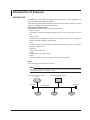
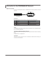
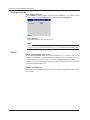
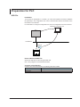
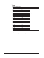
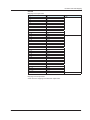
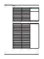
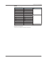
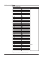
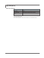
User’s
Manual
DX1000/DX1000N/DX2000
PROFIBUS-DP (/CP1)
Communication Interface
IM 04L41B01-19E
Yokogawa Electric Corporation
3rd Edition
Thank you for purchasing Daqstation DX1000, DX1000N, or DX2000 (Hereafter, called
"DX").
This manual explains the PROFIBUS-DP (/CP1 option) communication function of the DX.
Read this manual together with other User's Manuals (IM04L41B01-01E, IM04L42B01-01E,
and IM04L41B01-17E).
Notes
Trademarks
Revisions
● The content of this manual may change without prior notice in view of improving the
performance and function.
● We ensure the content of this manual. If, however, there are any mistakes or questionable
points, contact our branch office, branch store, or business office.
● Reprinting or reproduction of all or parts of the content of this manual is prohibited
without permission.
● We developed and created the TCP/IP software and TCP/IP software documents of this
product based on BSD Networking Software Release 1 licensed from the University of
California.
● vigilantplant, DAQSTATION, Daqstation, and DXAdvanced are our registered
trademarks.
● Microsoft and Windows are the registered trademarks or trademarks of Microsoft
Corporation in the United States and other countries.
● Adobe and Acrobat are the registered trademarks or trademarks of Adobe Systems
Incorporated.
● Kerberos is a trademark of the Massachusetts Institute of Technology (MIT).
● Other product and company names described in this manual are registered
trademarks or trademarks of their respective companies.
● This manual does not display marks ® and ™ for the registered trademarks or
trademarks of each company.
November 2008: 1st Edition
March 2010: 2nd Edition
December 2010: 3rd Edition
3rd Edition December 2010 (YK)
All Right Reserved, Copyright © 2008, Yokogawa Electric Corporation
IM 04L41B01-19E
Symbols Used in This Manual
● Units
• k: Denotes 1000. Examples: 5 kg, 100 kHz
• K: Denotes 1024. Example: 640 Kbytes
● Cautionary notes
In this User's Manual, cautionary notes are distinguished by the following symbols:
Refer to corresponding location on the instrument. This symbol
appears on dangerous locations on the instrument which require
special instructions for proper handling or use. The same symbol
appears in the corresponding place in the manual to identify those
instructions.
WARNING
Calls attention to actions or conditions that could cause serious
injury or death to the user, and precautions that can be taken to
prevent such occurrences.
CAUTION
Calls attentions to actions or conditions that could cause light
injury to the user or damage to the instrument or user’s data, and
precautions that can be taken to prevent such occurrences.
Note Calls attention to information that is important for proper operation of
the instrumen
● Bold characters
Denotes key or character string that appear on the DX screen.
The symbol indicates the key operation and menu selection procedure on the DX.
IM 04L41B01-19E
Assumption of Explanation
The explanation in this manual assumes that the DX is connected via communications
with Programmable Logic Controller (PLC). For information on how to operate PLCs, see
the user's manual of respective products.
This manual is intended for those who have used an PROFIBUS-DP.
In this manual, the screens of the DX1000 are used. The content displayed on the DX2000
screens are not different from those displayed on the DX1000 screen.
Revision History
Edition
1
2
3
IM 04L41B01-19E
DX
Release number 3
(Version 3.0x)
Style number 3
Release number 4
(Version 4.0x)
Style number 3
Same as edition 2.
Description
Newly published.
Additions and improvements to explanations.
Fixed explanations.
Contents
Symbols Used in This Manual....................................................................................................................2
Assumption of Explanation......................................................................................................................... 3
Revision History.......................................................................................................................................... 3
Introduction of Features.......................................................................................................................5
PROFIBUS-DP........................................................................................................................................... 5
What the DX Can Do.................................................................................................................................. 6
Settings of the DX....................................................................................................................................... 6
Access to the DX........................................................................................................................................ 6
Connection to the PROFIBUS-DP Network.........................................................................................7
Cable Connection....................................................................................................................................... 7
Settings of the DX....................................................................................................................................... 8
Others......................................................................................................................................................... 8
Preparation for PLC.............................................................................................................................9
GSD File..................................................................................................................................................... 9
Specification of Data................................................................................................................................. 10
Communication Connection...................................................................................................................... 10
I/O Buffer and Data Mapping.............................................................................................................11
Mapping Method of the I/O buffer............................................................................................................. 11
Data Count and Data Type....................................................................................................................... 11
Data Mapping........................................................................................................................................... 12
Specifications.....................................................................................................................................23
Basic Specifications.................................................................................................................................. 23
Index..................................................................................................................................................24
IM 04L41B01-19E
Introduction of Features
PROFIBUS-DP
PROFIBUS is an open field bus standard (IEC61158) used in various applications for
factory automation and process automation.
PROFIBUS-DP (Decentralized Periphery) is used for communication between PLCs and
remote I/O, enabling high-speed data transmission.
Configuration Components
PROFIBUS-DP network consists of following components:
• Class 1 master
A controller to exchange information with the slave in a cyclic manner. This is a PLC or
PC.
• Class 2 master
Engineering and configuration devices. This is either a PC on which configuration
software has been installed or software itself.
• Slave
I/O devices accessed by the master. This includes I/O devices, sensors, or actuaters.
The DX is a slave device.
• Terminator
The terminator of the bus.
•
•
Cable
A dedicated two-wire cable is used.
Others
Repeater, coupler, and other components are also used if needed.
Node
127 nodes can be connected to the network.
Note
For details of PROFIBUS specifications and information, see the documents published from the
PROFIBUS Organization in respective regions.
PROFIBU-DP Master (Class 1)
PLC etc.
Terminator
PROFIBU-DP Master (Class 2)
PC
Terminator
PROFIBUS-DP
Cable
Slave
IM 04L41B01-19E
Slave
Slave
Introduction of Features
What the DX Can Do
The DX provides the following functions:
• Participate in an PROFIBUS-DP network as a PROFIBUS-DP slave.
• Communicate with a PLC from Siemens.
• The master can access internal data of the DX.
Data
Access
Measurement channel data
Read
Computation channel*1 data
Read
Communication input data*1*2
Write
*1 This is an option (/M1 and /PM1).
*2 Communication input data, if coded in a calculation expression in the computation channel,
can be displayed on the DX.
The following shows examples of usage.
• Data on devices on a network can be recorded by a PLC to the DX.
• Data measured by the DX can be acquired by a PLC.
Settings of the DX
The DX is ready to use after the node address settings have been made.
Access to the DX
The DX is a passive device on an PROFIBUS-DP. The DX cannot initiate a request. PLC,
a class 1 master device, initiates a request and accesses the DX.
IM 04L41B01-19E
Connection to the PROFIBUS-DP Network
Cable Connection
Connect the PROFIBUS-DP cable to a PROFIBUS-DP connector provided on the back
of the DX.
5
4
3
2
1
(Rear panel)
9
8
7
6
Connector
D-sub 9-pin (female) connector. Each pin corresponds to the following signals.
Pin
Signal name
3
RxD/TxD - P
4
CNTR - P
5
DGND
6
VP + 5 V
8
RxD/TxD - N
Pins 1, 2, 7, and 9 are not used.
Explanation
Positive data receive/transmit.
RTS (for use by repeater).
Ground.
+ 5 V.
Negative data receive/transmit.
Cable
A dedicated two-wire cable is used (two wires for the signal). This is not supplied with the
DX. To be prepared separately.
Transmission Rate/Transmission Distance
The transmission rate varies depending on the transmission distance within the following
range.
9.6 Kbps/1200 m to 12 Mbps/100 m
Terminator
The DX has no built-in terminator circuit. If a terminator is needed in terms of wiring, use
a connector with a terminator.
IM 04L41B01-19E
Connection to the PROFIBUS-DP Network
Settings of the DX
Node Address Settings
Press MENU (to switch to setting mode), hold down FUNC for 3 s (to switch to basic
setting mode), and select the Menu tab > Communication (PROFIBUS).
• Node Address
Set a node address in the range of 0 to 125.
Note
The node address of PROFIBUS-DP can be checked on the Network Information Screen of the
DX. You can open the Network Information Screen by pressing FUNC > Network info softkey.
Others
Status Output (option, /F1 and /F2)
If setting Communication error of the Status Output (/F1 or /F2 option) to On, a relay
output is provided when a PROFIBUS-DP communication error occurs within the DX. If
a communication error occurs, contact your nearest YOKOGAWA dealer for repairs.
See Section 2.9 of the DX1000/DX1000N User's Manual (IM04L41B01-01E) or DX2000
User's Manual (IM04142B01-01E).
In Basic Setting Mode:
When the DX is in the basic setting mode, communications are available but input/output
data is invalid.
IM 04L41B01-19E
Preparation for PLC
GSD File
Installation
To have the DX participate in a network, you must first install the DX device database
file (GSD file) in the configuration tool. A PLC communicates with the DX based on the
information in the GSD file.
For information on using the configuration tool, see the configuration tool user's manual.
PROFIBUS configuration tool
PLC
PROFIBU-DP
GSD file
DX
How to Obtain the GSD File
Obtain the GSD file from the Yokogawa Web site:
URL: www.yokogawa.com/ns/dxadv/download/
Contents of the GSD File
Contents other than those listed in the following table are omitted.
Item
Model Name
Slave Family
IM 04L41B01-19E
Description
Data Acquisition PROFIBUS I/F
0
Preparation for PLC
Specification of Data
If you install the GSD file, the DX is added to the configuration tool as a "General" type
"Slave". Select [Model] to expand the module list and select your DX model from the list.
Item
Model
Data Acquisition PROFIBUS I/F
Module
DX1002
DX1002/M1
DX1004
DX1004/M1
DX1006
DX1006/M1
DX1012
DX1012/M1
DX2004
DX2004/M1
DX2008
DX2008/M1
DX2010
DX2010/M1
DX2020
DX2020/M1
DX2030
DX2030/M1
DX2040
DX2040/M1
DX2048
DX2048/M1
Explanation
The model name described in the GSD file. Select the device to
be configured from the model name of the "General" type and
the "Slave" in the devices tree or list box.
The DX models are referred to as modules. Selecting the
model "Data Acquisition PROFIBUS I/F" allows you to select a
module.
DX1002, DX1002N, without Option/M1 and /PM1
DX1002, DX1002N, with Option/M1 or /PM1
DX1004, DX1004N, without Option/M1 and /PM1
DX1004, DX1004N, with Option/M1 or /PM1
DX1006, DX1006N, without Option/M1 and /PM1
DX1006, DX1006N, with Option/M1 or /PM1
DX1012, DX1012N, without Option/M1 and /PM1
DX1012, DX1012N, with Option/M1 or /PM1
DX2004, without Option/M1 and /PM1
DX2004, with Option/M1 or /PM1
DX2008, without Option/M1 and /PM1
DX2008, with Option/M1 or /PM1
DX2010, without Option/M1 and /PM1
DX2010, with Option/M1 or /PM1
DX2020, without Option/M1 and /PM1
DX2020, with Option/M1 or /PM1
DX2030, without Option/M1 and /PM1
DX2030, with Option/M1 or /PM1
DX2040, without Option/M1 and /PM1
DX2040, with Option/M1 or /PM1
DX2048, without Option/M1 and /PM1
DX2048, with Option/M1 or /PM1
Communication Connection
You can establish a communication connection by using the configuraton tool and run
it with a PLC. For information on using the configuration tool and a PLC, see the user's
manuals of these products.
10
IM 04L41B01-19E
I/O Buffer and Data Mapping
A master device such as a PLC accesses internal data of the DX via the "Input buffer"
and "Output buffer" of the DX. "Input" represents an input to the master, while "Output"
represents an output from the master.
Mapping Method of the I/O buffer
The "Input buffer" and "Output buffer" of the DX for PROFIBUS-DP communication has
128 bytes each. Data is laid out as described in the following table. Data layout cannot
be changed.
Buffer
Input
Application
Reading
measurement channel
data and computation
channel data
Description
Locates all the measurement channel data from the top of
the buffer. Locates as much computation channel data as
possible in the remaining part of the buffer.
Buffer
Output
Application
Writing
communication input
data
Description
Locates as much communication input data as possible.
Data Count and Data Type
The DX data count is as follows:
Model
Measurement channel
Computation channel
DX1002
DX1004
DX1006
DX1012
DX2004
DX2008
DX2010
Count
2
4
6
12
4
8
10
Count
12
Number
101 to 112
24
101 to 124
12
101 to 112
Number
001, 002
001 to 004
001 to 006
001 to 012
001 to 004
001 to 008
001 to 010
60
Communication input
data
Count
Number
24
C01 to C24
60
C01 to C32
(C33 to C60)*1
101 to 127
(128 to 160)*1
DX2020
20
001 to 020
101 to 122
(123 to 160)*1
DX2030
30
001 to 030
101 to 117
(118 to 160)*1
DX2040
40
001 to 040
101 to 112
(113 to 160)*1
DX2048
48
001 to 048
101 to 108
(109 to 160)*1
*1 Data in parentheses cannot be located in a buffer because it exceeds the capacity of the I/O
buffer.
Note
The communication input data for C01 to C24 (on the DX1000) or for C01 to C32 (on the
DX2000) is reserved for PROFIBUS-DP.
You cannot write to these data numbers through other means (such as Modbus, EtherNet/IP, or
communication commands).
IM 04L41B01-19E
11
I/O Buffer and Data Mapping
Data Mapping
Data mapping for each model is shown in the table. The following symbols are used in
the table.
Symbol
Explanation
CH1, CH2
Data of the measurement channel 1 or measurement channel 2.
CH101, CH112
Data of the computation channel 101 or computation channel 112.
C01, C24
Communication input data.
INT16
16-bit signed integer.
INT32_B
32-bit signed integer, BigEndian*.
* BigEndian: Assuming that a value of 01020304H is located as 01 02 03 04 in the buffer.
Note
• To acquire a physical value of the measurement channel data or computation channel data,
it is necessary to obtain the decimal place and unit information in advance.
• The channel data or communication input data that cannot be allocated in the I/O buffer is
not supported..
DX1002
Mapping of the input buffer
Offset
0–1
2–3
4–7
8 – 11
12 – 15
16 – 19
20 – 23
24 – 27
28 – 31
32 – 35
36 – 39
40 – 43
44 – 47
48 – 51
52 – 127
12
Description
CH1
CH2
CH101
CH102
CH103
CH104
CH105
CH106
CH107
CH108
CH109
CH110
CH111
CH112
Always 0.
Data type
INT16
INT32_B
-
IM 04L41B01-19E
I/O Buffer and Data Mapping
Mapping of the output buffer
Offset
0–3
4–7
8 – 11
12 – 15
16 – 19
20 – 23
24 – 27
28 – 31
32 – 35
36 – 39
40 – 43
44 – 47
48 – 51
52 – 55
56 – 59
60 – 63
64 – 67
68 – 71
72 – 75
76 – 79
80 – 83
84 – 87
88 – 91
92 – 95
96 – 127
Description
C01
C02
C03
C04
C05
C06
C07
C08
C09
C10
C11
C12
C13
C14
C15
C16
C17
C18
C19
C20
C21
C22
C23
C24
Ignore anything that is written.
Data type
INT32_B
Description
CH1
CH2
CH3
CH4
CH101
CH102
CH103
CH104
CH105
CH106
CH107
CH108
CH109
CH110
CH111
CH112
Always 0.
Data type
INT16
-
DX1004
Mapping of the input buffer
Offset
0–1
2–3
4–5
6–7
8 – 11
12 – 15
16 – 19
20 – 23
24 – 27
28 – 31
32 – 35
36 – 39
40 – 43
44 – 47
48 – 51
52 – 55
56 – 127
INT32_B
-
Mapping of the output buffer
Same as for the mapping of the DX1002 output buffer.
IM 04L41B01-19E
13
I/O Buffer and Data Mapping
DX1006
Mapping of the input buffer
Offset
0–1
2–3
4–5
6–7
8–9
10 – 11
12 – 15
16 – 19
20 – 23
24 – 27
28 – 31
32 – 35
36 – 39
40 – 43
44 – 47
48 – 51
52 – 55
56 – 59
60 – 63
64 – 67
68 – 71
72 – 75
76 – 79
80 – 83
84 – 87
88 – 91
92 – 95
96 – 99
100 – 103
104 – 107
108 – 127
Description
CH1
CH2
CH3
CH4
CH5
CH6
CH101
CH102
CH103
CH104
CH105
CH106
CH107
CH108
CH109
CH110
CH111
CH112
CH113
CH114
CH115
CH116
CH117
CH118
CH119
CH120
CH121
CH122
CH123
CH124
Always 0.
Data type
INT16
INT32_B
-
Mapping of the output buffer
Same as for the mapping of the DX1002 output buffer.
14
IM 04L41B01-19E
I/O Buffer and Data Mapping
DX1012
Mapping of the input buffer
Offset
0–1
2–3
4–5
6–7
8–9
10 – 11
12 – 13
14 – 15
16 – 17
18 – 19
20 – 21
22 – 23
24 – 27
28 – 31
32 – 35
36 – 39
40 – 43
44 – 47
48 – 51
52 – 55
56 – 59
60 – 63
64 – 67
68 – 71
72 – 75
76 – 79
80 – 83
84 – 87
88 – 91
92 – 95
96 – 99
100 – 103
104 – 107
108 – 111
112 – 115
116 – 119
120 – 127
Description
CH1
CH2
CH3
CH4
CH5
CH6
CH7
CH8
CH9
CH10
CH11
CH12
CH101
CH102
CH103
CH104
CH105
CH106
CH107
CH108
CH109
CH110
CH111
CH112
CH113
CH114
CH115
CH116
CH117
CH118
CH119
CH120
CH121
CH122
CH123
CH124
Always 0.
Data type
INT16
INT32_B
-
Mapping of the output buffer
Same as for the mapping of the DX1002 output buffer.
IM 04L41B01-19E
15
I/O Buffer and Data Mapping
DX2004
Mapping of the input buffer
Offset
0–1
2–3
4–5
6–7
8 – 11
12 – 15
16 – 19
20 – 23
24 – 27
28 – 31
32 – 35
36 – 39
40 – 43
44 – 47
48 – 51
52 – 55
56 – 127
Description
CH1
CH2
CH3
CH4
CH101
CH102
CH103
CH104
CH105
CH106
CH107
CH108
CH109
CH110
CH111
CH112
Always 0.
Data type
INT16
Description
C01
C02
C03
C04
C05
C06
C07
C08
C09
C10
C11
C12
C13
C14
C15
C16
C17
C18
C19
C20
C21
C22
C23
C24
C25
C26
C27
C28
C29
C30
C31
C32
Data type
INT32_B
NT32_B
-
Mapping of the output buffer
Offset
0–3
4–7
8 – 11
12 – 15
16 – 19
20 – 23
24 – 27
28 – 31
32 – 35
36 – 39
40 – 43
44 – 47
48 – 51
52 – 55
56 – 59
60 – 63
64 – 67
68 – 71
72 – 75
76 – 79
80 – 83
84 – 87
88 – 91
92 – 95
96 – 99
100 – 103
104 – 107
108 – 111
112 – 115
116 – 119
120 – 123
124 – 127
16
IM 04L41B01-19E
I/O Buffer and Data Mapping
DX2008
Mapping of the input buffer
Offset
0–1
2–3
4–5
6–7
8–9
10 – 11
12 – 13
14 – 15
16 – 19
20 – 23
24 – 27
28 – 31
32 – 35
36 – 39
40 – 43
44 – 47
48 – 51
52 – 55
56 – 59
60 – 63
64 – 127
Description
CH1
CH2
CH3
CH4
CH5
CH6
CH7
CH8
CH101
CH102
CH103
CH104
CH105
CH106
CH107
CH108
CH109
CH110
CH111
CH112
Always 0.
Data type
INT16
NT32_B
-
Mapping of the output buffer
Same as for the mapping of the DX2004 output buffer.
IM 04L41B01-19E
17
I/O Buffer and Data Mapping
DX2010
Mapping of the input buffer
Offset
0–1
2–3
4–5
6–7
8–9
10 – 11
12 – 13
14 – 15
16 – 17
18 – 19
20 – 23
24 – 27
28 – 31
32 – 35
36 – 39
40 – 43
44 – 47
48 – 51
52 – 55
56 – 59
60 – 63
64 – 67
68 – 71
72 – 75
76 – 79
80 – 83
84 – 87
88 – 91
92 – 95
96 – 99
100 – 103
104 – 107
108 – 111
112 – 115
116 – 119
120 – 123
124 – 127
Description
CH1
CH2
CH3
CH4
CH5
CH6
CH7
CH8
CH9
CH10
CH101
CH102
CH103
CH104
CH105
CH106
CH107
CH108
CH109
CH110
CH111
CH112
CH113
CH114
CH115
CH116
CH117
CH118
CH119
CH120
CH121
CH122
CH123
CH124
CH125
CH126
CH127
Data type
INT16
INT32_B
Mapping of the output buffer
Same as for the mapping of the DX2004 output buffer.
18
IM 04L41B01-19E
I/O Buffer and Data Mapping
DX2020
Mapping of the input buffer]
Offset
0–1
2–3
4–5
6–7
8–9
10 – 11
12 – 13
14 – 15
16 – 17
18 – 19
20 – 21
22 – 23
24 – 25
26 – 27
28 – 29
30 – 31
32 – 33
34 – 35
36 – 37
38 – 39
40 – 43
44 – 47
48 – 51
52 – 55
56 – 59
60 – 63
64 – 67
68 – 71
72 – 75
76 – 79
80 – 83
84 – 87
88 – 91
92 – 95
96 – 99
100 – 103
104 – 107
108 – 111
112 – 115
116 – 119
120 – 123
124 – 127
Description
CH1
CH2
CH3
CH4
CH5
CH6
CH7
CH8
CH9
CH10
CH11
CH12
CH13
CH14
CH15
CH16
CH17
CH18
CH19
CH20
CH101
CH102
CH103
CH104
CH105
CH106
CH107
CH108
CH109
CH110
CH111
CH112
CH113
CH114
CH115
CH116
CH117
CH118
CH119
CH120
CH121
CH122
Data type
INT16
INT32_B
Mapping of the output buffer
Same as for the mapping of the DX2004 output buffer.
IM 04L41B01-19E
19
I/O Buffer and Data Mapping
DX2030
Mapping of the input buffer
Offset
0–1
2–3
4–5
6–7
8–9
10 – 11
12 – 13
14 – 15
16 – 17
18 – 19
20 – 21
22 – 23
24 – 25
26 – 27
28 – 29
30 – 31
32 – 33
34 – 35
36 – 37
38 – 39
40 – 41
42 – 43
44 – 45
46 – 47
48 – 49
50 – 51
52 – 53
54 – 55
56 – 57
58 – 59
60 – 63
64 – 67
68 – 71
72 – 75
76 – 79
80 – 83
84 – 87
88 – 91
92 – 95
96 – 99
100 – 103
104 – 107
108 – 111
112 – 115
116 – 119
120 – 123
124 – 127
Description
CH1
CH2
CH3
CH4
CH5
CH6
CH7
CH8
CH9
CH10
CH11
CH12
CH13
CH14
CH15
CH16
CH17
CH18
CH19
CH20
CH21
CH22
CH23
CH24
CH25
CH26
CH27
CH28
CH29
CH30
CH101
CH102
CH103
CH104
CH105
CH106
CH107
CH108
CH109
CH110
CH111
CH112
CH113
CH114
CH115
CH116
CH117
Data type
INT16
INT32_B
Mapping of the output buffer
Same as for the mapping of the DX2004 output buffer.
20
IM 04L41B01-19E
I/O Buffer and Data Mapping
DX2040
Mapping of the input buffer
Offset
0–1
2–3
4–5
6–7
8–9
10 – 11
12 – 13
14 – 15
16 – 17
18 – 19
20 – 21
22 – 23
24 – 25
26 – 27
28 – 29
30 – 31
32 – 33
34 – 35
36 – 37
38 – 39
40 – 41
42 – 43
44 – 45
46 – 47
48 – 49
50 – 51
52 – 53
54 – 55
56 – 57
58 – 59
60 – 61
62 – 63
64 – 65
66 – 67
68 – 69
70 – 71
72 – 73
74 – 75
76 – 77
78 – 79
80 – 83
84 – 87
88 – 91
92 – 95
96 – 99
100 – 103
104 – 107
108 – 111
112 – 115
116 – 119
120 – 123
124 – 127
Description
CH1
CH2
CH3
CH4
CH5
CH6
CH7
CH8
CH9
CH10
CH11
CH12
CH13
CH14
CH15
CH16
CH17
CH18
CH19
CH20
CH21
CH22
CH23
CH24
CH25
CH26
CH27
CH28
CH29
CH30
CH31
CH32
CH33
CH34
CH35
CH36
CH37
CH38
CH39
CH40
CH101
CH102
CH103
CH104
CH105
CH106
CH107
CH108
CH109
CH110
CH111
CH112
Data type
INT16
INT32_B
Mapping of the output buffer
Same as for the mapping of the DX2004 output buffer.
IM 04L41B01-19E
21
I/O Buffer and Data Mapping
DX2048
Mapping of the input buffer
Offset
0–1
2–3
4–5
6–7
8–9
10 – 11
12 – 13
14 – 15
16 – 17
18 – 19
20 – 21
22 – 23
24 – 25
26 – 27
28 – 29
30 – 31
32 – 33
34 – 35
36 – 37
38 – 39
40 – 41
42 – 43
44 – 45
46 – 47
48 – 49
50 – 51
52 – 53
54 – 55
56 – 57
58 – 59
60 – 61
62 – 63
64 – 65
66 – 67
68 – 69
70 – 71
72 – 73
74 – 75
76 – 77
78 – 79
80 – 81
82 – 83
84 – 85
86 – 87
88 – 89
90 – 91
92 – 93
94 – 95
96 – 99
100 – 103
104 – 107
108 – 111
112 – 115
116 – 119
120 – 123
124 – 127
Description
CH1
CH2
CH3
CH4
CH5
CH6
CH7
CH8
CH9
CH10
CH11
CH12
CH13
CH14
CH15
CH16
CH17
CH18
CH19
CH20
CH21
CH22
CH23
CH24
CH25
CH26
CH27
CH28
CH29
CH30
CH31
CH32
CH33
CH34
CH35
CH36
CH37
CH38
CH39
CH40
CH41
CH42
CH43
CH44
CH45
CH46
CH47
CH48
CH101
CH102
CH103
CH104
CH105
CH106
CH107
CH108
Data type
INT16
INT32_B
Mapping of the output buffer
Same as for the mapping of the DX2004 output buffer.
22
IM 04L41B01-19E
Specifications
Basic Specifications
Item
Data mapping
Node address
Interface
Transmission media
Transmission rate/Transmission
distance
Terminator
Specifications
See "I/O Buffer and Data Mapping".
0 to 125
PROFIBUS-DP-V0 Slave
Dedicated two-wire cable (two wire for the signal)
9.6 Kbps/1200 m to 12 Mbps/100 m
Not built-in (External termination is required.)
The DX data update interval
The DX data is updated in a scan interval. However, it is not faster than 250 ms.
IM 04L41B01-19E
23
Index
Index
C
cable.......................................................................................5, 7
cable connection.........................................................................7
class 1 master.............................................................................5
class 2 master.............................................................................5
communication input data.........................................................11
computation channel.................................................................11
configuration components...........................................................5
configuration tool.........................................................................9
connector.....................................................................................7
D
data count..................................................................................11
data mapping.............................................................................12
data type....................................................................................11
decimal place............................................................................12
DX settings..................................................................................6
G
GSD file.......................................................................................9
I
input buffer.................................................................................11
installation...................................................................................9
M
mapping method........................................................................11
measurement channel...............................................................11
N
node............................................................................................5
node address........................................................................8, 23
O
output buffer..............................................................................11
P
programmable logic controller.....................................................3
R
release number...........................................................................3
revision history............................................................................3
S
slave............................................................................................5
specifications.............................................................................23
standard......................................................................................5
status output................................................................................8
style number................................................................................3
symbols (used in the manual).....................................................2
T
terminator...............................................................................5, 7
transmission distance..................................................................7
transmission rate.........................................................................7
U
unit.............................................................................................12
24
IM 04L41B01-19E