1
Allen-Bradley
1771–DB Basic
Module
User
Manual
I–1
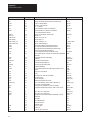
Table of Contents
Using This Manual . . . . . . . . . . . . . . . . . . . . . . . . . . . . . . .
1
1.1
1.2
1.3
1.4
1.5
1.6
1
1
1
1
2
2
Chapter Objectives . . . . . . . . . . . . . . . . . . . . . . . . . . . . . . .
What this manual contains . . . . . . . . . . . . . . . . . . . . . . . . . .
Audience . . . . . . . . . . . . . . . . . . . . . . . . . . . . . . . . . . . . . .
Definitions of major terms . . . . . . . . . . . . . . . . . . . . . . . . . . .
Important information . . . . . . . . . . . . . . . . . . . . . . . . . . . . . .
Conventions . . . . . . . . . . . . . . . . . . . . . . . . . . . . . . . . . . . .
Introducing the BASIC Module . . . . . . . . . . . . . . . . . . . . . .
1
2.1 Chapter Objectives . . . . . . . . . . . . . . . . . . . . . . . . . . . . . . .
2.2 General Features . . . . . . . . . . . . . . . . . . . . . . . . . . . . . . . .
2.3 Hardware Features . . . . . . . . . . . . . . . . . . . . . . . . . . . . . . . .
2.4 Software Features . . . . . . . . . . . . . . . . . . . . . . . . . . . . . . . .
2.5 Specifications . . . . . . . . . . . . . . . . . . . . . . . . . . . . . . . . . . .
1
1
2
3
4
Installing the BASIC Module . . . . . . . . . . . . . . . . . . . . . . .
1
3.1 Chapter Objectives . . . . . . . . . . . . . . . . . . . . . . . . . . . . . . . .
3.2 Installing the BASIC module . . . . . . . . . . . . . . . . . . . . . . . . .
3.2.1 Power Requirements . . . . . . . . . . . . . . . . . . . . . . . . . . . . .
3.2.2 Module Location in the I/O Chassis . . . . . . . . . . . . . . . . . . .
3.2.3 Module Keying . . . . . . . . . . . . . . . . . . . . . . . . . . . . . . . . .
3.2.4 Configuration Plugs . . . . . . . . . . . . . . . . . . . . . . . . . . . . . .
3.2.5 Module Installation . . . . . . . . . . . . . . . . . . . . . . . . . . . . . . .
3.2.6 Initial Start-up Procedure . . . . . . . . . . . . . . . . . . . . . . . . . .
3.3 Module Status LED’s . . . . . . . . . . . . . . . . . . . . . . . . . . . . . .
3.4 Installing the User Prom . . . . . . . . . . . . . . . . . . . . . . . . . . . .
3.4.1 Electrostatic Discharge . . . . . . . . . . . . . . . . . . . . . . . . . . .
3.5 Battery . . . . . . . . . . . . . . . . . . . . . . . . . . . . . . . . . . . . . . . .
3.5 Battery (continued) . . . . . . . . . . . . . . . . . . . . . . . . . . . . . . . .
1
1
2
2
2
3
5
5
6
7
9
9
10
Using the Serial Ports . . . . . . . . . . . . . . . . . . . . . . . . . . . .
I–1
4.1 Chapter Objectives . . . . . . . . . . . . . . . . . . . . . . . . . . . . . . . .
4.2 Using the BASIC Module Program and Peripheral
Communication Ports . . . . . . . . . . . . . . . . . . . . . . . . . . . . . .
4.2.1 Pin Descriptions . . . . . . . . . . . . . . . . . . . . . . . . . . . . . . . .
4.3 Program Port . . . . . . . . . . . . . . . . . . . . . . . . . . . . . . . . . . . .
4.3 Program Port (continued) . . . . . . . . . . . . . . . . . . . . . . . . . . .
4.3.1 Using the XOFF/XON Commands for the Program Port . . . .
4.3.2 Connecting a T3/T4 Industrial Terminal to the Program Port .
4.3.3 Connecting a T30 Industrial Terminal (Cat. No. 1784-T30) to the
Program Port . . . . . . . . . . . . . . . . . . . . . . . . . . . . . . . . . . . .
I–1
I–1
I–3
I–5
I–6
I–7
I–8
I–9
ii
Table of Contents
4.3.4 Connecting a T50 Industrial Terminal (Cat. No. 1784-T50)
to the Program Port . . . . . . . . . . . . . . . . . . . . . . . . . . . . . . .
4.3.4.1 Configuring the Software . . . . . . . . . . . . . . . . . . . . . . . .
4.3.4.2 Wiring . . . . . . . . . . . . . . . . . . . . . . . . . . . . . . . . . . . . .
4.4 Peripheral Port . . . . . . . . . . . . . . . . . . . . . . . . . . . . . . . . . . .
4.4.1 Using the XON/XOFF Commands for the Peripheral Port . . .
4.4.2 Connecting A T30 Industrial Terminal (1784-T30)
to the Peripheral Port . . . . . . . . . . . . . . . . . . . . . . . . . . . . . .
4.4.2.1 Hardware Configuration . . . . . . . . . . . . . . . . . . . . . . . .
4.4.3 Connecting a 1770-SA/SB Recorder to the Peripheral Port . .
4.4.4 Connecting a 1770-HC Printer to the Peripheral Port . . . . . .
4.4.5 Connecting RS-422 Devices . . . . . . . . . . . . . . . . . . . . . . . .
4.5 Cable Assembly Parts . . . . . . . . . . . . . . . . . . . . . . . . . . . . .
I–9
I–10
I–10
I–11
I–12
I–12
I–14
I–15
I–15
I–16
I–19
Operating Functions . . . . . . . . . . . . . . . . . . . . . . . . . . . . .
1
5.1 Chapter Objectives . . . . . . . . . . . . . . . . . . . . . . . . . . . . . . . .
5.2 Definition of Terms . . . . . . . . . . . . . . . . . . . . . . . . . . . . . . . .
5.2.1 Commands . . . . . . . . . . . . . . . . . . . . . . . . . . . . . . . . . . . .
5.2.2 Statements . . . . . . . . . . . . . . . . . . . . . . . . . . . . . . . . . . . .
5.2.3 Format Statements . . . . . . . . . . . . . . . . . . . . . . . . . . . . . .
5.2.4 Data Format . . . . . . . . . . . . . . . . . . . . . . . . . . . . . . . . . . .
5.2.5 Integers . . . . . . . . . . . . . . . . . . . . . . . . . . . . . . . . . . . . . .
5.2.6 Constants . . . . . . . . . . . . . . . . . . . . . . . . . . . . . . . . . . . . .
5.2.7 Operators . . . . . . . . . . . . . . . . . . . . . . . . . . . . . . . . . . . . .
5.2.8 Variables . . . . . . . . . . . . . . . . . . . . . . . . . . . . . . . . . . . . .
5.2.9 Expressions . . . . . . . . . . . . . . . . . . . . . . . . . . . . . . . . . . .
5.2.10 Relational Expressions . . . . . . . . . . . . . . . . . . . . . . . . . . .
5.2.11 System Control Values . . . . . . . . . . . . . . . . . . . . . . . . . . .
5.2.12 Argument Stack . . . . . . . . . . . . . . . . . . . . . . . . . . . . . . . .
5.2.13 Control Stack . . . . . . . . . . . . . . . . . . . . . . . . . . . . . . . . .
5.3 Description of Commands . . . . . . . . . . . . . . . . . . . . . . . . . . .
5.3.1 Command: RUN . . . . . . . . . . . . . . . . . . . . . . . . . . . . . . . .
5.3.2 Command: CONT . . . . . . . . . . . . . . . . . . . . . . . . . . . . . . .
5.3.3 Command: LIST . . . . . . . . . . . . . . . . . . . . . . . . . . . . . . . .
5.3.4 Command: LIST# or LIST[ . . . . . . . . . . . . . . . . . . . . . . . . .
5.3.5 Command: NEW . . . . . . . . . . . . . . . . . . . . . . . . . . . . . . . .
5.3.6 Command: NULL [integer] . . . . . . . . . . . . . . . . . . . . . . . . .
5.3.7 Command: Control C . . . . . . . . . . . . . . . . . . . . . . . . . . . . .
5.3.7.1 Command: Disabling Control C . . . . . . . . . . . . . . . . . . .
5.3.8 Command: Control S . . . . . . . . . . . . . . . . . . . . . . . . . . . . .
5.3.9 Command: Control Q . . . . . . . . . . . . . . . . . . . . . . . . . . . . .
5.3.10 Overview of EPROM File Commands . . . . . . . . . . . . . . . .
5.3.11 Commands: RAM and ROM [integer] . . . . . . . . . . . . . . . . .
5.3.11.1 RAM . . . . . . . . . . . . . . . . . . . . . . . . . . . . . . . . . . . . .
5.3.11.2 ROM . . . . . . . . . . . . . . . . . . . . . . . . . . . . . . . . . . . . .
1
1
1
1
2
2
2
3
3
3
4
4
4
5
5
6
6
7
7
8
9
9
9
9
10
10
10
10
11
11
Table of Contents
5.3.12 Command: XFER . . . . . . . . . . . . . . . . . . . . . . . . . . . . . .
5.3.13 Command: PROG . . . . . . . . . . . . . . . . . . . . . . . . . . . . . .
5.3.13.1 User PROM Check and Description – CALL 81 . . . . . . .
5.3.14 Command: PROG1 . . . . . . . . . . . . . . . . . . . . . . . . . . . . .
5.3.15 Command: PROG2 . . . . . . . . . . . . . . . . . . . . . . . . . . . . .
5.4 Description of Statements . . . . . . . . . . . . . . . . . . . . . . . . . . .
5.4.1 Statement: CALL [integer] . . . . . . . . . . . . . . . . . . . . . . . . .
5.4.2 Statement: CLEAR . . . . . . . . . . . . . . . . . . . . . . . . . . . . . .
5.4.3 Statement: CLEARI (clear interrupts) . . . . . . . . . . . . . . . . . .
5.4.4 Statement: CLEARS . . . . . . . . . . . . . . . . . . . . . . . . . . . . .
5.4.5 Statements: CLOCK1 and CLOCK0 . . . . . . . . . . . . . . . . . .
CLOCK1 . . . . . . . . . . . . . . . . . . . . . . . . . . . . . . . . . . . . . . . . .
CLOCK0 . . . . . . . . . . . . . . . . . . . . . . . . . . . . . . . . . . . . . . . . .
5.4.6 Statements: DATA – READ – RESTORE . . . . . . . . . . . . . .
DATA . . . . . . . . . . . . . . . . . . . . . . . . . . . . . . . . . . . . . . . . . . .
READ . . . . . . . . . . . . . . . . . . . . . . . . . . . . . . . . . . . . . . . . . . .
RESTORE . . . . . . . . . . . . . . . . . . . . . . . . . . . . . . . . . . . . . . .
5.4.7 Statement: DIM . . . . . . . . . . . . . . . . . . . . . . . . . . . . . . . . .
5.4.8 Statements: DO – UNTIL [rel expr] . . . . . . . . . . . . . . . . . . .
5.4.10 Statement: END . . . . . . . . . . . . . . . . . . . . . . . . . . . . . . .
5.4.11 Statements: FOR – TO – (STEP) – NEXT . . . . . . . . . . . . .
5.4.12 Statements: GOSUB [ln num] – RETURN . . . . . . . . . . . . .
GOSUB . . . . . . . . . . . . . . . . . . . . . . . . . . . . . . . . . . . . . . . . .
RETURN . . . . . . . . . . . . . . . . . . . . . . . . . . . . . . . . . . . . . . . .
5.4.13 Statement: GOTO [ln num] . . . . . . . . . . . . . . . . . . . . . . . .
5.4.14 Statements: ON [expr] GOTO [ln num], [ln num],...[ln num],
ON [expr] GOSUB[ln num], [ln num],...[ln num] . . . . . . . . . . . .
5.4.15 Statements: IF – THEN – ELSE . . . . . . . . . . . . . . . . . . . .
5.4.16 Statement: INPUT . . . . . . . . . . . . . . . . . . . . . . . . . . . . . .
5.4.17 Statement: LD@ [expr] . . . . . . . . . . . . . . . . . . . . . . . . . . .
5.4.18 Statement: LET . . . . . . . . . . . . . . . . . . . . . . . . . . . . . . . .
5.4.19 Statement: ONERR [ln num) . . . . . . . . . . . . . . . . . . . . . . .
5.4.20 Statement: ONTIME [expr],[ln num] . . . . . . . . . . . . . . . . . .
5.4.21 Statement: PRINT or P. . . . . . . . . . . . . . . . . . . . . . . . . . .
5.4.22 Special Print Formatting Statements . . . . . . . . . . . . . . . . .
5.4.22.1 PRINT TAB([expr]) . . . . . . . . . . . . . . . . . . . . . . . . . . .
5.4.22.2 PRINT SPC([expr]) . . . . . . . . . . . . . . . . . . . . . . . . . . .
5.4.22.3 PRINT CR . . . . . . . . . . . . . . . . . . . . . . . . . . . . . . . . .
5.4.22.4 PRINT USING (special characters) . . . . . . . . . . . . . . .
5.4.22.5 PRINT USING(Fx) . . . . . . . . . . . . . . . . . . . . . . . . . . .
5.4.22.6 PRINT USING(#.#) . . . . . . . . . . . . . . . . . . . . . . . . . . .
5.4.22.7 PRINT USlNG(0) . . . . . . . . . . . . . . . . . . . . . . . . . . . .
5.4.22.8 Reset Print Head Pointer – CALL 99 . . . . . . . . . . . . . .
5.4.23 Statement: PRINT# or P.# . . . . . . . . . . . . . . . . . . . . . . . .
5.4.24 Statements: PH0., PH1., PH0.#, PH1.# . . . . . . . . . . . . . . .
5.4.25 Statement: PUSH[expr] . . . . . . . . . . . . . . . . . . . . . . . . . .
iii
12
12
13
14
14
16
16
16
16
17
17
17
17
18
18
18
18
19
19
22
22
23
23
24
24
25
25
26
28
29
30
31
32
33
33
33
33
34
34
35
35
36
36
37
38
iv
Table of Contents
5.4.26 Statement: POP[var] . . . . . . . . . . . . . . . . . . . . . . . . . . . .
5.4.27 Statement: REM . . . . . . . . . . . . . . . . . . . . . . . . . . . . . . .
5.4.28 Statement: RETI . . . . . . . . . . . . . . . . . . . . . . . . . . . . . . .
5.4.19 Statement: ST@ [expr] . . . . . . . . . . . . . . . . . . . . . . . . . . .
5.4.30 Statement: STOP . . . . . . . . . . . . . . . . . . . . . . . . . . . . . .
5.4.31 Statement: STRING . . . . . . . . . . . . . . . . . . . . . . . . . . . . .
5.5 Description of Arithmetic, and Logical Operators
and Expressions . . . . . . . . . . . . . . . . . . . . . . . . . . . . . . . . . .
5.5.1 Dual Operand (dyadic) Operators . . . . . . . . . . . . . . . . . . . .
5.5.1.1 Comments on logical operators .AND.,.OR. and .XOR. . .
5.5.2 Unary Operators . . . . . . . . . . . . . . . . . . . . . . . . . . . . . . . .
5.5.2.1 General Purpose Operators . . . . . . . . . . . . . . . . . . . . .
5.5.2.2 Log Functions . . . . . . . . . . . . . . . . . . . . . . . . . . . . . . .
5.5.2.3 Trig Functions . . . . . . . . . . . . . . . . . . . . . . . . . . . . . . .
5.5.2.4 Comments on Trig Functions . . . . . . . . . . . . . . . . . . . .
5.5.3 Understanding Precedence of Operators . . . . . . . . . . . . . . .
5.5.4 How Relational Expressions Work . . . . . . . . . . . . . . . . . . . .
5.6 Special Operators . . . . . . . . . . . . . . . . . . . . . . . . . . . . . . . .
5.6.1 Special Function Operators . . . . . . . . . . . . . . . . . . . . . . . .
5.6.1.1 GET . . . . . . . . . . . . . . . . . . . . . . . . . . . . . . . . . . . . . .
5.6.1.2 TIME . . . . . . . . . . . . . . . . . . . . . . . . . . . . . . . . . . . . .
5.6.2 System Control Values . . . . . . . . . . . . . . . . . . . . . . . . . . . .
5.6.2.1 MTOP . . . . . . . . . . . . . . . . . . . . . . . . . . . . . . . . . . . . .
5.6.2.2 LEN . . . . . . . . . . . . . . . . . . . . . . . . . . . . . . . . . . . . . .
5.7 Data Transfer Support Routines . . . . . . . . . . . . . . . . . . . . . .
5.7.1 Update Block-Transfer-Read Buffer (timed) – CALL 2 . . . . . .
5.7.2 Update Block-Transfer-Write Buffer (timed) – CALL 3 . . . . . .
5.7.3 Set Block-Transfer-Write Length – CALL 4 . . . . . . . . . . . . . .
5.7.4 Set Block-Transfer-Read Length – CALL 5 . . . . . . . . . . . . .
5.7.5 Update Block-Transfer-Write Buffer – CALL 6 . . . . . . . . . . .
5.7.6 Update Block-Transfer-Read Buffer – CALL 7 . . . . . . . . . . .
5.7.7 Disable Interrupts – CALL 8 . . . . . . . . . . . . . . . . . . . . . . . .
5.7.8 Enable Interrupts – CALL 9 . . . . . . . . . . . . . . . . . . . . . . . .
5.7.9 Input Call Conversion Routines . . . . . . . . . . . . . . . . . . . . . .
5.7.9.1 3-Digit Signed, Fixed Decimal BCD to Internal
Floating Point ”XXX – CALL 10 . . . . . . . . . . . . . . . . . . . . . .
5.7.9.2 16-Bit Binary (4-digit hex) to Internal Floating
Point – CALL 11 . . . . . . . . . . . . . . . . . . . . . . . . . . . . . . . . .
5.7.9.3 4-Digit Signed Octal to Internal Floating
Point ”XXXX – CALL 12 . . . . . . . . . . . . . . . . . . . . . . . . . . .
5.7.9.4 6-Digit, Signed, Fixed Decimal BCD to Internal
Floating Point ”XXXXXX – CALL 13 . . . . . . . . . . . . . . . . . . .
5.7.9.5 4-Digit BCD to Internal Floating Point XXXX – CALL 17 . .
5.7.10 Output Call Conversion Routines . . . . . . . . . . . . . . . . . . .
5.7.10.1 Internal Floating Point to 3-Digit, Signed, Fixed Decimal
BCD ”XXX – CALL 20 . . . . . . . . . . . . . . . . . . . . . . . . . . . . .
39
40
41
41
41
42
43
43
44
45
45
46
46
47
48
49
50
50
50
50
52
52
52
52
53
53
54
54
54
54
54
55
55
55
55
55
56
56
56
57
Table of Contents
5.7.10.2 Internal Floating Point to 16-Bit Unsigned Binary
(4 digit hex) – CALL 21 . . . . . . . . . . . . . . . . . . . . . . . . . . .
5.7.10.3 Internal Floating Point to 4-Digit, Signed
Octal ”XXXX–Call 22 . . . . . . . . . . . . . . . . . . . . . . . . . . . . .
5.7.10.4 Internal Floating Point to 6-Digit, Signed, Fixed Decimal
BCD ”XXXXXX – CALL 23 . . . . . . . . . . . . . . . . . . . . . . . . .
5.7.10.5 Internal Floating Point to 3.3-digit, Signed, Fixed Decimal
BCD ”XXX.XXX – CALL 26 . . . . . . . . . . . . . . . . . . . . . . . . .
5.7.10.6 Internal Floating Point to 4-digit BCD XXXX – CALL 27 .
5.8 Peripheral Port Support . . . . . . . . . . . . . . . . . . . . . . . . . . . .
5.8.1 Peripheral Port Support – Parameter Set – CALL 30 . . . . . . .
5.8.2 Peripheral Port Support – Display Peripheral Port
Parameters –CALL 31 . . . . . . . . . . . . . . . . . . . . . . . . . . . . .
5.8.3 Save Program to Data Recorder – CALL 32 . . . . . . . . . . . . .
5.8.4 Verify Program with Data Recorder – CALL 33 . . . . . . . . . . .
5.8.5 Load Program from Data Recorder – CALL 34 . . . . . . . . . . .
5.8.6 Get Numeric Input Character from Peripheral Port – CALL 35
5.8.7 Get the Number of Characters in the Peripheral
Port Buffers – CALL 36 . . . . . . . . . . . . . . . . . . . . . . . . . . . . .
5.8.8 Clear the Peripheral Ports Input or Output Buffer – CALL 37 .
5.8.9 Save Labeled Program to Data Recorder
(1770-SB only) – CALL 38 . . . . . . . . . . . . . . . . . . . . . . . . . . .
5.8.10 Load Labeled Program from Data Recorder
(1770-SB only) – CALL 39 . . . . . . . . . . . . . . . . . . . . . . . . . . .
5.8.11 Print the Peripheral Port Output Buffer and
Pointer – CALL 110 . . . . . . . . . . . . . . . . . . . . . . . . . . . . . . .
5.8.12 Print the Peripheral Port Input Buffer and Pointer – CALL 111
5.8.13 Reset the Peripheral Port to Default Settings – CALL 119 . .
5.9 Wall Clock Support Calls . . . . . . . . . . . . . . . . . . . . . . . . . . . .
5.9.1 Setting the Wall Clock Time (Hour, Minute, Second) – CALL 40
5.9.2 Setting the Wall Clock Date (Day, Month, Year) – CALL 41 . .
5.9.3 Set Wall Clock – Day of Week – CALL 42 . . . . . . . . . . . . . .
5.9.4 Date/Time Retrieve String – CALL 43 . . . . . . . . . . . . . . . . .
5.9.5 Date Retrieve Numeric (Day, Month, Year) – CALL 44 (2) . . .
5.9.6 Time Retrieve String – CALL 45 . . . . . . . . . . . . . . . . . . . . .
5.9.7 Time Retrieve Number – Call 46 . . . . . . . . . . . . . . . . . . . . .
5.9.8 Retrieve Day of Week String – CALL 47 . . . . . . . . . . . . . . .
5.9.9 Retrieve Day of Week Numeric – CALL 48 . . . . . . . . . . . . . .
5.9.10 Date Retrieve String – CALL 52 . . . . . . . . . . . . . . . . . . . .
5.10 Description of String Operators . . . . . . . . . . . . . . . . . . . . . .
5.10.1 The ASC Operator . . . . . . . . . . . . . . . . . . . . . . . . . . . . . .
5.10.2 The CHR Operator . . . . . . . . . . . . . . . . . . . . . . . . . . . . . .
5.10.2.1 Clearing the Screen on an Allen-Bradley
Industrial Terminal . . . . . . . . . . . . . . . . . . . . . . . . . . . . . . .
5.10.2.2 Cursor Positioning on an Industrial Terminal . . . . . . . . .
5.10.3 String Support Calls . . . . . . . . . . . . . . . . . . . . . . . . . . . . .
5.10.3.1 String Repeat – CALL 60 . . . . . . . . . . . . . . . . . . . . . .
v
57
57
58
58
58
59
59
60
61
61
62
63
65
65
65
66
66
67
67
67
68
68
68
69
69
69
70
70
70
71
71
72
74
74
75
75
80
vi
Table of Contents
5.10.3.2 String Append (Concatenation) – CALL 61 . . . . . . . . . .
5.10.3.3 Number to String Conversion – CALL 62 . . . . . . . . . . .
5.10.3.4 String to Number Conversion – CALL 63 . . . . . . . . . . .
5.10.3.5 Find a String in a String – CALL 64 . . . . . . . . . . . . . . .
5.10.3.6 Replace a String in a String – CALL 65 . . . . . . . . . . . .
5.10.3.7 Insert String in a String – CALL 66 . . . . . . . . . . . . . . . .
5.10.3.8 Delete String from a String – CALL 67 . . . . . . . . . . . . .
5.10.3.9 Determine Length of a String – CALL 68 . . . . . . . . . . .
5.11 Memory Support Calls . . . . . . . . . . . . . . . . . . . . . . . . . . . .
5.11.1 ROM to RAM Program Transfer – CALL 70 . . . . . . . . . . . .
5.11.2 ROM/RAM to ROM Program Transfer – CALL 71 . . . . . . .
5.11.3 RAM/ROM Return – CALL 72 . . . . . . . . . . . . . . . . . . . . .
5.11.4 Battery-backed RAM Disable – CALL 73 . . . . . . . . . . . . .
5.11.5 Battery-backed RAM Enable – CALL 74 . . . . . . . . . . . . . .
5.11.6 Protected Variable Storage – CALL 77 . . . . . . . . . . . . . . .
5.12 Miscellaneous Calls . . . . . . . . . . . . . . . . . . . . . . . . . . . . . .
5.12.1 Program Port Baud Rate – CALL 78 . . . . . . . . . . . . . . . . .
5.12.2 Blink the Active LED by Default – CALL 79 . . . . . . . . . . . .
5.12.3 Check Battery Condition – CALL 80 . . . . . . . . . . . . . . . . .
5.12.4 User PROM Check and Description – CALL 81 . . . . . . . . .
5.12.5 Reset Print Head Pointer – CALL 99 . . . . . . . . . . . . . . . . .
5.12.6 Print the Argument Stack – CALL 109 . . . . . . . . . . . . . . . .
5.12.7 Print the Peripheral Port Output Buffer and
Pointer – CALL 110 . . . . . . . . . . . . . . . . . . . . . . . . . . . . . . .
5.12.8 Print the Peripheral Port Input Buffer and
Pointer – CALL 111 . . . . . . . . . . . . . . . . . . . . . . . . . . . . . . . .
5.12.9 Reset the Peripheral Port to Default
Settings – CALL 119 . . . . . . . . . . . . . . . . . . . . . . . . . . . . . .
81
81
82
83
84
85
86
87
87
88
88
89
90
90
90
92
92
93
93
93
94
94
Programming . . . . . . . . . . . . . . . . . . . . . . . . . . . . . . . . . . .
1
6.1 Chapter Objectives . . . . . . . . . . . . . . . . . . . . . . . . . . . . . . .
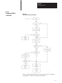
6.2 Block-Transfer with the BASIC Module . . . . . . . . . . . . . . . . .
6.2.1 Block-Transfer-Write and Block-Transfer-Read Buffers . . . .
6.3 Block-Transfer with PLC-2 Family Processors . . . . . . . . . . . .
6.3.1 PLC-2 Processor Program . . . . . . . . . . . . . . . . . . . . . . . .
6.3.1.1 Rung Description . . . . . . . . . . . . . . . . . . . . . . . . . . . . .
6.4 PLC-3 Family Processors . . . . . . . . . . . . . . . . . . . . . . . . . .
6.4.1 Rung Description for Sample PLC-3 Family Ladder
Logic – Single Data Set . . . . . . . . . . . . . . . . . . . . . . . . . . . . .
6.5 PLC-5 Family Processors . . . . . . . . . . . . . . . . . . . . . . . . . .
6.5.1 Rung Description for Sample PLC-5 Family Ladder Logic . .
6.6. Block-Transfer Programming Tips . . . . . . . . . . . . . . . . . . . .
1
1
1
2
2
3
5
94
94
95
7
7
9
10
Table of Contents
vii
Data Types . . . . . . . . . . . . . . . . . . . . . . . . . . . . . . . . . . . . .
1
7.1 Chapter Objectives . . . . . . . . . . . . . . . . . . . . . . . . . . . . . . .
7.2 Output Data Types . . . . . . . . . . . . . . . . . . . . . . . . . . . . . . .
7.2.1 16-bit Binary (4 Hex Digits) . . . . . . . . . . . . . . . . . . . . . . . .
7.2.2 3-digit, Signed, Fixed Decimal BCD . . . . . . . . . . . . . . . . . .
7.2.3 4-digit, Unsigned, Fixed Decimal BCD . . . . . . . . . . . . . . . .
7.2.4 4-digit, Signed, Octal . . . . . . . . . . . . . . . . . . . . . . . . . . . . .
7.2.5 6-digit, Signed, Fixed Decimal BCD . . . . . . . . . . . . . . . . . .
7.2.6 3.3-digit, Signed, Fixed Decimal BCD . . . . . . . . . . . . . . . .
7.3 Input Data Types . . . . . . . . . . . . . . . . . . . . . . . . . . . . . . . . .
1
1
1
2
2
3
4
5
6
Editing A Procedure . . . . . . . . . . . . . . . . . . . . . . . . . . . . . .
1
8.2 Chapter Objectives . . . . . . . . . . . . . . . . . . . . . . . . . . . . . . .
8.2 Entering the Edit Mode . . . . . . . . . . . . . . . . . . . . . . . . . . . .
8.3 Editing Commands/Features . . . . . . . . . . . . . . . . . . . . . . . .
8.3.1 Move . . . . . . . . . . . . . . . . . . . . . . . . . . . . . . . . . . . . . . . .
8.3.2 Replace . . . . . . . . . . . . . . . . . . . . . . . . . . . . . . . . . . . . . .
8.3.3 Insert . . . . . . . . . . . . . . . . . . . . . . . . . . . . . . . . . . . . . . . .
8.3.4 Delete . . . . . . . . . . . . . . . . . . . . . . . . . . . . . . . . . . . . . . .
8.3.5 Retype . . . . . . . . . . . . . . . . . . . . . . . . . . . . . . . . . . . . . . .
8.3.6 Exits . . . . . . . . . . . . . . . . . . . . . . . . . . . . . . . . . . . . . . . .
8.3.7 Renumber . . . . . . . . . . . . . . . . . . . . . . . . . . . . . . . . . . . .
8.4 Editing a Simple Procedure . . . . . . . . . . . . . . . . . . . . . . . . .
1
1
1
1
1
2
2
2
2
2
4
Error Messages and Anomalies . . . . . . . . . . . . . . . . . . . . .
1
9.1 Chapter Objectives . . . . . . . . . . . . . . . . . . . . . . . . . . . . . . .
9.2 Error Messages from BASIC . . . . . . . . . . . . . . . . . . . . . . . .
9.3 Error Messages from CALL Routines . . . . . . . . . . . . . . . . . .
9.3.1 Data Conversion CALL Error Messages . . . . . . . . . . . . . .
9.3.2 Peripheral Port Support CALL Error Messages . . . . . . . . . .
9.3.3 Wall Clock CALL Error Messages . . . . . . . . . . . . . . . . . . .
9.3.4 String Support CALL Error Messages . . . . . . . . . . . . . . . .
9.3.5 Memory Support CALL Error Messages . . . . . . . . . . . . . . .
9.3.6 Miscellaneous CALL Error Messages . . . . . . . . . . . . . . . .
9.4 Anomalies . . . . . . . . . . . . . . . . . . . . . . . . . . . . . . . . . . . . .
1
1
3
3
3
4
5
6
7
7
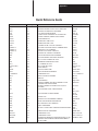
Quick Reference Guide . . . . . . . . . . . . . . . . . . . . . . . . . . .
1
Decimal/Hexadecimal/Octal/ASCII Conversion Table . . . . .
1
Basic Module Programming Hints . . . . . . . . . . . . . . . . . . .
1
BASIC Module Programming Hints . . . . . . . . . . . . . . . . . . . . . . .
1
Chapter 1
Using This Manual
1.1
Chapter Objectives
Read this chapter before you use the BASIC Module. It tells you how to
use this manual properly and efficiently.
1.2
What this manual contains
This manual shows you how to install and operate your module. It gives
you information about:
hardware specifications.
installing the module.
the BASIC instruction set.
programming the module.
This manual is not a BASIC tutorial document. We assume that you are
familiar with BASIC programming.
1.3
Audience
Before you read this manual or try to use the BASIC Module, you should
be familiar with the operation of the 1771 I/O structure as it relates to your
particular processor. Refer to our Publication Index (publication number
SD499) for the appropriate Programming and Operations manual.
1.4
Definitions of major terms
To make this manual easier for you to read and understand, we avoid
repeating product names where possible. We refer to the:
BASIC Language Module (Cat. No. 1771-DB) as the BASIC Module.
Industrial Terminal System (Cat. No. 1770-T3/T4) as the industrial
terminal.
Data Recorder (Cat. No. 1770-SA/SB) as the 1770-SA/SB Recorder.
RS-232-C compatible devices which communicate with the BASIC
Module, such as the Industrial Terminal, SA/SB Recorder, computers,
robots, barcode readers, or data terminals, as RS-423A/RS-232C
devices.
Chapter 1
Using This Manual
1.5
Important information
There are three different types of precautionary statements in this manual:
Important, CAUTION and WARNING.
Important: used to point out specific areas of concern when operating
your BASIC Module.
CAUTION: used to make you aware of instances where damage to your
equipment could occur.
WARNING: used to make you aware of instances where personal injury
could occur.
1.6
Conventions
In this manual, we use certain notational conventions to indicate
keystrokes and items displayed on a CRT or printer. A keystroke is shown
in parentheses:
(ENTER)
1–2
Chapter 2
Introducing the BASIC Module
2.1
Chapter Objectives
This chapter discusses the functions and features of the BASIC Module.
When you finish reading this chapter, you should:
understand and be able to identify the hardware components of the
BASIC Module.
understand the basic features and functions of the BASIC Module.
2.2
General Features
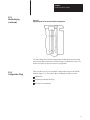
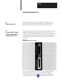
The BASIC Module (figure 2.1) provides math functions, report generation
and BASIC language capabilities for any Allen-Bradley processor that
communicates with the 1771 I/O system using block-transfer. It provides:
basic programming using the Intel BASIC-52 language.
math functions consistent with the BASIC-52 definition.
two independently configurable serial ports capable of connecting to
various user devices.
user accessible real-time clock with 5 ms resolution.
user accessible “wall” clock/calendar with 1 second resolution.
program generation and editing using a dumb ASCII terminal or a
T3/T4 Industrial Terminal in alphanumeric mode.
program storage and retrieval using the 1770-SA/SB Recorder.
block-transfer communication capability from a PLC-2, PLC-3 or
PLC-5 family processor.
on board program PROM burning.
Chapter 2
Introducing the BASIC Module
2.2
General Features (continued)
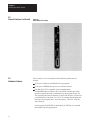
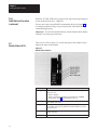
Figure 2.1
BASIC Module Front Edge
2.3
Hardware Features
Your module is a one-slot module with the following functions and
features:
13 K bytes of battery backed RAM for user programs.
32 K bytes of EPROM storage for user software routines.
One RS-423A/232C compatible serial communications
port(PROGRAM port) which works with ASCII terminals providing
operator program interaction, command level input printer output, etc.
The program port baud rate defaults to 1200 baud. Initially you must set
your terminal for 1200 baud. Use CALL 78 to change the program port
baud rate. The program port is fixed at no parity, 1 start bit, 1 stop bit
and 8 data bits.
It also supports XON/XOFF for interruption of LISTing or to suspend
data output from the program port.
2–2
Chapter 2
Introducing the BASIC Module
2.3
Hardware Features
(continued)
One RS-423A/232C/RS-422 compatible serial communications port
(PERIPHERAL port), supporting bi-directional XON/XOFF software
handshaking and RTS/CTS, DTR, DSR, DCD hardware handshaking for
interfacing to printers and commercial asynchronous modems. You can
change the peripheral port configuration using a CALL 30. (Refer to
Section 5.8.1). Default values are: 1 start bit, 1 stop bit, 8 bits/character,
no parity, handshaking off and 1200 baud. The baud rate is jumper
selectable (300 to 19.2 K bps). (Refer to Section 3.2.4 titled,
“Configuration Plugs”).
Interface to the 1771 I/O rack backplane to support block-transfer.
Wall clock/calendar with battery back-up available for program access.
Battery replacement without removing the module from the I/O rack.
All power derived from the backplane (1.5 A).
Multiple BASIC modules can reside in the same I/O rack and function
independently of each other.
2.4
Software Features
Your module runs BASIC language programs in an interactive mode
through the dumb terminal/programming port interface, or on power-up.
The execution of these programs allows a direct interface with
programmable controller ladder programs.
Your module uses the following devices and features:
terminal for programming, editing, system commands, displaying data
and interactive program dialog
serial port for report generation output, upload/download to
1770-SA/SB Recorder
PLC-2, PLC-3 and PLC-5 data table reads and writes using
block-transfer
We provide routines to use both the real-time clock and the
wall-clock/calendar. The wall-clock time base is seconds.
2–3
Chapter 2
Introducing the BASIC Module
2.4
Software Features
(continued)
You can start program execution:
by entering commands at the interactive terminal.
at power-up initialization.
You can store and execute programs in RAM or EPROM. You can store
one user-program in RAM and up to 255 (depending on program size)
independent user-programs simultaneously in EPROM memory.
The programs run single-task mode only. You can generate the following
data types with the BASIC Module:
16-bit binary (4 hex digits)
3-digit, signed, fixed decimal BCD
4-digit, unsigned, fixed decimal BCD
4-digit, signed, octal
6-digit, signed, fixed decimal BCD
3.3 digit, signed, fixed decimal BCD
Refer to Chapter 7, “Data Types” for more information.
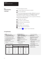
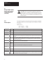
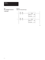
2.5 Specifications
Isolation
G Formats: integer, decimal,
and exponential
G hexadecimal
The Programming
Port is isolated from
G The Peripheral Port is isolated from
Wall-clock
G Formats: accuracy
integer, decimal,
G Formats: integer, decimal,
hexadecimal and exponential
G hexadecimal
Absolute: v and
" 5exponential
min/month @ 25° C
Module location
@@@@
Drive
output +3.6 V minimum
G Drift v " 50
ppm/°C
G One 1771 I/O chassis module slot
G Drift v " 50 ppm/year @ 25°C
the 1771 I/O backplane. (+500 V)
G The Programming Port is isolated from
the Peripheral Port. (+500 V)
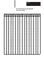
Communication Rates
G 300, 600, 1200, 2400, 4800, 9600,
19.2 K bits
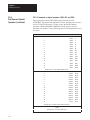
G Communication rates/distances
Port driver and receiver
G Drive output +3.6 V minimum
@@@@
G Receiver sensitivity 200 mV minimum
@@@@
Math
G Precision: 8 significant digits
G Range: "1E-127 to
"99999999E+127
the 1771 I/O backplane. (+500 V)
2–4
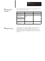
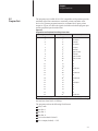
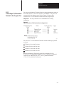
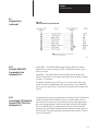
@@@@
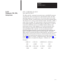
Maximum Distance Allowed
Communication
ommunication
Rate (bps)
RS-232-C
RS-423
RS-422
300
50
4000
4000
600
50
3000
4000
1200
50
2500
4000
4800
50
800
4000
9600
50
400
4000
19,200
50
200
4000
Backplane power supply load
G 1.5 A
Environmental Conditions
G Operational temperature: 0°C to 60°C
(32°F to 140°F)
G Storage temperature: -40°C to 85°C
(-40°F to 185°F)
G Relative humidity: 5% to 95%
(non-condensing)
Keying (top backplane connector)
G Between 8 and 10
G Between 32 and 34
Chapter 3
Installing the BASIC Module
3.1
Chapter Objectives
This chapter describes how to install your BASIC module in a 1771 I/O
rack. After reading this chapter you should be able to:
configure the module using the configuration plugs.
insert the module into a 1771 I/O backplane.
understand module status indicators.
install additional EPROM’s.
3.2
Installing the BASIC module
WARNING: Disconnect and lockout all AC power from the
programmable controller and system power supplies before
installing modules to avoid injury to personnel and damage to
equipment.
Read this installation section completely before beginning. Re-check all
option selections and connections before you begin programming.
Before installing your module in the I/O chassis you must:
1.
calculate the power requirements of all the modules in each chassis.
(Refer to Section 3.2.1 below).
2.
determine the location of the module in the I/O chassis. (Refer to
Section 3.2.2 below).
3.
key the backplane connectors in the I/O chassis. (Refer to Section
3.2.3 below).
4.
set the module configuration plugs. (Refer to Section 3.2.4 below).
Chapter 3
Installing the BASIC Module
3.2.1
Power Requirements
Your module receives its power through the 1771 I/O chassis backplane
from the chassis power supply. It does not require any other external power
supply to function. When planning your system you must consider the
power usage of all modules in the I/O chassis to prevent overloading the
chassis backplane and/or power supply. Each BASIC module requires 1.5
A at +5V DC. Add this to the requirements of all other modules in the I/O
chassis.
CAUTION: Do not insert or remove modules from the I/O
chassis while system power is on. Failure to observe this rule
may result in damage to module circuitry.
3.2.2
Module Location in the I/O
Chassis
You can place your module in any I/O slot of the I/O chassis except for the
extreme left slot. This slot is reserved for processors or adapter modules.
You can place your module in the same module group as a discrete high
density module if you are using processors or adapters with single-slot
addressing capabilities.
Important: Certain processors restrict the placement of block-transfer
output modules. Refer to the user manual for your particular processor for
more information.
3.2.3
Module Keying
Initially you can insert your module into any I/O module slot in the I/O
chassis. However, once you designate a slot for a module you must not
insert other modules into these slots. We strongly recommend that you use
the plastic keying bands shipped with each I/O chassis, to key I/O slots to
accept only one type of module. Your module is slotted in two places on
the rear edge of the board. The position of the keying bands on the
backplane connector must correspond to these slots to allow insertion of
the module. You may key any I/O rack connector to receive the module
assembly. Snap the keying bands onto the upper backplane connectors
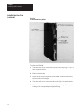
between the numbers printed on the backplane (figure 3.1).
Between 8 and 10
Between 32 and 34
3–2
Chapter 3
Installing the BASIC Module
3.2.3
Module Keying
(continued)
Figure 3.1
Keying Diagram for Placement of Module Keying Bands
You may change the position of these bands if subsequent system design
and rewiring makes insertion of a different type of module necessary. Use
needle-nose pliers to insert or remove keying bands.
3.2.4
Configuration Plugs
There are three sets of user selectable configuration plugs on the BASIC
Module (figure 3.2). You can use these configuration plugs to select:
PROM size.
peripheral port baud rate (bps).
422 receiver termination.
3–3
Chapter 3
Installing the BASIC Module
3.2.4
Configuration Plugs
(continued)
Figure 3.2
The Configuration Plugs
All other configuration plugs are factory set. Do not reset these factory set
configuration plugs.
3–4
Chapter 3
Installing the BASIC Module
3.2.5
Module Installation
3.2.6
Initial Start-up Procedure
Now that you have determined the configuration, power requirements,
location, keying and wiring for your module, you are ready to install it in
the I/O chassis.
1.
Turn off power to the I/O chassis.
2.
Insert your module in the I/O rack. Plastic tracks on the top and
bottom of the slots guide the module into position. Do not force the
module into its backplane connector. Apply firm, even pressure on
the module to seat it properly. Note the rack, module group and slot
numbers and enter them in the module address section of the
block-transfer instructions.
3.
Snap the I/O chassis latch over the module. This secures the module
in place.
You must use the following procedure when powering up the module for
the first time. This procedure is a continuation of the installation procedure
presented above.
4.
Connect the cable from your program terminal to the BASIC Module
program port.
CAUTION: Be sure you properly ground the system be fore
turning on power. A difference in ground potential between the
BASIC Module serial connectors and your program terminal or
other serial device can cause damage to the equipment or loss of
module programs.
5.
Turn on your program terminal. Select 1200 baud. If you are using an
industrial terminal, select the Alpha Numeric mode, baud rate and
press [RETURN].
6.
Turn on power to the rack. The following sequence takes place:
Fault (FLT) and ACTIVE LED’s go on.
FLT and ACTIVE LED’s go out until power-up diagnostics is
complete. Ignore any other LED activity during power-up.
ACTIVE LED goes on.
3–5
Chapter 3
Installing the BASIC Module
3.2.6
Initial Start-up Procedure
(continued)
When the ACTIVE LED comes on observe the sign-on message displayed
on the terminal followed by tREADY.
You are now ready to begin BASIC programming. Refer to Chapter 6 for
an example program to help you get your processor and BASIC Module
communicating properly.
Important: If you break communications with the module check that the
terminal is set at the proper baud rate.
3.3
Module Status LED’s
There are five LED’s (figure 3.3) on the front panel of the module which
indicate the status of the module.
Figure 3.3
Module Status Indicators
LED
ACTIVE (green)
Description
Indicates the module has passed power-up diagnostics. You can program
using CALL 79 to:
G remain on (default).
G remain on in RUN mode and blink every second when in COMMAND
mode. Refer to Chapter 5 for an explanation of CALL 79.
3–6
XMTG (green)
ON when data is transmitting on the peripheral port. Lights for either RS-422
or RS-423/RS-232C output.
RCVG (green)
ON when data is transmitting on the peripheral port. Lights for either RS-422
or RS-423/RS-232C input. This LED does not indicate whether or not valid
data was received.
FAULT (red)
When LED is on, indicates either a hardware problem or block-transfer
problem. See below.
BAT LOW (red)
Lights when the battery voltage drops below about 3.0V DC.
Chapter 3
Installing the BASIC Module
3.3
Module Status LED’s
(continued)
If the FLT LED lights after the module has been operating properly check
the following troubleshooting chart.
Problem
Probable Cause
Recommended Action
Module’s programming port
does not respond
Hardware failure
Send module for repair
Module’s programming port
continues to function but FLT
LED goes on and off
Problem with block-transfers
between processor and BASIC
module
Verify ladder logic
Problem with block-transfer
circuitry on the BASIC Module
Send module for repair
Module’s programming port
continues to function and FLT
LED goes out when processor
is switched to program mode
Module’s programming port
continues to function and FLT
LED remains on
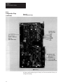
3.4
Installing the User Prom
The BASIC Module has a 32 K byte EPROM installed (figure 3.4). We
recommend that you keep JEDEC standard 8 K, 16 K or 32 K byte
EPROMs which use 12.5V DC programming voltage as spares. You can
buy 32 K byte EPROMs from Allen-Bradley (part numbers 940654-02 or
9406454-03).
3–7
Chapter 3
Installing the BASIC Module
Installing the User Prom
(continued)
Figure 3.4
User PROM and Battery Holder
To replace the EPROM:
3–8
1.
Turn the small screw in the socket just above the chip (figure 3.4) 1/4
turn counterclockwise.
2.
Remove the old chip.
3.
Insert the new chip with pin one down and the center notch down as
shown in the socket diagram.
4.
Turn the small screw in the socket above the chip 1/4 turn clockwise.
5.
Refer to the above section titled, “Configuration Plugs” for the proper
setting of the corresponding configuration plug.
Chapter 3
Installing the BASIC Module
3.4.1
Electrostatic Discharge
Electrostatic discharge can damage integrated circuits or semiconductors in
this module if you touch backplane connector pins. It can also damage the
module when you set configuration plugs and/or switches inside the
module. Avoid electrostatic damage by observing the following
precautions:
Touch a grounded object to rid yourself of charge before handling the
module.
Do not touch the backplane connector or connector pins.
If you configure or replace internal components, do not touch other
circuit components inside the module. If available, use a static-safe
work station.
When not in use, keep the module in its static-shield bag.
CAUTION: Electrostatic discharge can degrade performance
or damage the module. Handle as stated above.
3.5
Battery
The 13 K bytes of user RAM and the clock/calendar are battery backed.
Drain on the battery should be less than 0.5 mA DC during battery back-up
(no power) and less than 50 uA while the module is powered. Battery life
during no-power conditions is about 2000 hours. Battery shelf life is about
20,000 hours. When the BAT LOW indicator comes on the battery should
maintain the clock and program data for about three days. We recommend
immediate replacement.
To replace the battery (figure 3.4):
1.
Place a screwdriver in the battery cover slot.
2.
Press inwards slightly.
3.
Rotate the screwdriver and battery cover counterclockwise 1/4 turn.
4.
Release the pressure and remove the battery cover.
5.
Replace the battery with the positive (+) terminal out.
6.
Replace the battery cover.
3–9
Chapter 3
Installing the BASIC Module
3.5
Battery (continued)
The BAT LOW indicator should go out.
You can monitor the battery low condition in revision A and revision B
modules using a XBY(77B4H) statement. Bit 2 high indicates the battery
low condition.
With revision C modules use CALL 80 to monitor battery status.
3–10
Chapter 4
Using the Serial Ports
4.1
Chapter Objectives
This chapter describes how to use the program serial port and the
peripheral serial port to connect terminals, Data Cartridge Recorders,
Digital Cassette Recorders, printers and other compatible devices.
4.2
Using the BASIC Module
Program and Peripheral
Communication Ports
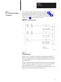
The BASIC Module has a program serial port and a peripheral serial port
capable of connecting to various user devices (figure 4.1). You can
configure each port independently. Both ports are electrically isolated from
each other and from the backplane up to 500 V with no external power
needed. Both ports operate from 300 baud to 19.2K baud and default to
1200 baud.
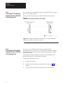
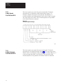
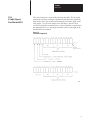
Figure 4.1
Program/Peripheral Port Locations
If you use an RS-423/RS-232 device or an Allen-Bradley Industrial
Terminal you can use up to a 50 foot maximum cable length for
connections from either the program or peripheral ports. Refer to the
specifications section in Chapter 2 for cable length recommendations.
Chapter 4
Using the Serial Ports
4.2
Using the BASIC Module
Program and Peripheral
Communication Ports
(continued)
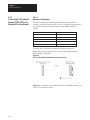
4.2.1
Pin Descriptions
CAUTION: Be sure you properly ground the system before
turning on power. A difference in ground potential between the
BASIC Module serial connectors and your program terminal or
other serial device can cause damage to the equipment or loss of
module programs.
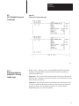
Use the following pins for connections made to the program or peripheral
ports. Refer to figure 4.2 for pin descriptions. Not all signals are available
on both ports.
Signal states are:
mark = logical 1 = – voltage
space = logical 0 = + voltage
Pin
Name
Description
11
Chassis/
Shield
Connect this pin to chassis ground for shielding purposes.
21
TXD
TXD is an RS-423A compatible serial output port.
31
RXD
RXD is an RS-423A compatible serial input data port.
4
RTS
RTS is an RS-423 compatible hardware handshaking output line. This line changes to a mark (1) state when the
BASIC Module has data in the output queue and is requesting permission to transmit to the data communications
equipment.
5
CTS
CTS is an RS-423A compatible hardware handshaking input line. This line must be in a mark (1) state for the
BASIC Module to transmit on the peripheral port. If no corresponding signal exists on the data communications
equipment, connect CTS to RTS.
6
DSR
DSR is a general purpose RS-423A compatible input line. The BASIC Module transmits or receives in the mark (1)
or space (0) state. Use this line for data recorder interface.
71,9,10
Signal
Common
Use the signal common pins to reference all RS-423A/RS-422 compatible signals.
8
DCD
If DCD is enabled using CALL 30, the BASIC Module does not transmit or receive characters until the DCD line is
in the mark (1) state. When disabled, the module ignores the state of this line.
11,12,13,15
17,19,21,22
NC
No connection
14,25
422 TXD
RS-422A compatible equivalent of the RS-423A TXD line. Differential serial output lines.
16, 18
422 RXD
Differential RS-422A compatible serial input lines.
20
DTR
DTR is an RS-423A compatible hardware handshaking output line. This line changes to a space (0) state when the
BASIC Module input queue has accumulated more than 223 characters. The DTR line changes to a mark (1) state
when the input queue contains less than 127 characters.
23,24
1program
4–2
port pins
Chapter 4
Using the Serial Ports
4.3
Program Port
The program port is an RS-423A/232C compatible serial port that provides
minimum signal line connection to terminals, printers and other serial
devices for operator-program interaction, command level input, printer
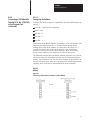
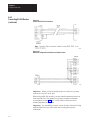
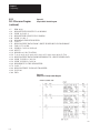
output etc. Figure 4.2 shows the signals available on both the program port
and the peripheral port described later.
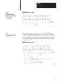
Figure 4.2
Program Port and Peripheral Port Wiring Connections
Program Port
Peripheral Port
11
11
Description
Chassis/Shield
21
21
TXD-Output
31
31
RXD-lnput
4
41
RTS-Output
5
6
51
61
CTS-lnput
DSR-lnput
71
71
Signal Common
8
81
DCD-lnput
9
91
Signal Common
10
101
Signal Common
11
11
NC
12
12
NC
13
13
NC
14
141
RS-422 TXD
15
15
NC
16
161
RS-422 RXD
17
17
NC
18
181
RS-422 RXD’
19
19
NC
20
20
DTR-Output
21
21
NC
22
22
NC
23
23
NC
24
24
NC
25
251
RS-422 TXD’
1Signal is provided on this pin
The baud rate is initially set at 1200 baud. You can use CALL 78 to change
the baud rate from 300 to 19.2K bps.
The program port has the following fixed format:
parity: none
start bits: 1
stop bits: 1
data bits: 8
receiver threshold: 200 mV
driver output (loaded): +3.6V
4–3
Chapter 4
Using the Serial Ports
4.3
Program Port (continued)
Important: The program port always resets the most significant bit of all
its data inputs. The range of each byte of data is 0 to 127 (7FH). On output,
the module transmits all bits as specified when using the PRINT CHR()
command except for the XOFF (13H) character. The range of each byte of
data is 0 to 255 (OFFH).
Important: The program port automatically inserts a CR, LF sequence
after the 79th character column. Use CALL 99 to reset the column counter
to zero to allow PRINT page width’s in excess of 79 characters.
You enter BASIC programs through a dumb ASCII terminal, such as an
industrial terminal in alphanumeric mode. Refer to section 4.3.2,
“Connecting a T3/T4 Industrial Terminal to the Program Port”.
4.3.1
Using the XOFF/XON
Commands for the
Program Port
Use the XOFF/XON commands to disable outputs from the program port
in the following way.
1.
Use XOFF only on PRINT statements.
2.
When XOFF is received during a PRINT, data output and program
execution are suspended immediately.
3.
When XOFF is received at any other time, program execution
continues until a PRINT is encountered. When a PRINT is
encountered program execution is suspended.
4.
Use XON to resume program execution.
The program port accepts uppercase or lowercase input, however, the
input receiver changes all commands, keywords or variables to upper
case before storing in memory, thus:
u10 print “hello”(CR)
appears as
10 PRINT “hello”
when listed.
4–4
Chapter 4
Using the Serial Ports
4.3.2
Connecting a T3/T4 Industrial
Terminal to the Program Port
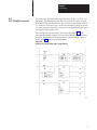
You can use an Industrial Terminal System as the programming system for
the BASIC Module. Connect the module to CHANNEL C only. You can
construct cable for distances up to 50 feet. Figure 4.3 shows cable
connections to a T3/T4 Industrial Terminal from the program port.
Important: You may continue to use CHANNEL B in existing
installations.
Figure 4.3
Cable Connection to T3/T4 Terminal from the Program Port
You can use a T3 or T4 Industrial Terminal with the following keyboard
revisions:
T3 Series A, Revision H or later
T3 Series B, Revision H or later
T3 Series C, Revision A or later
T4 Series A, Revision F or later
Refer to the Industrial Terminal Systems User’s Manual (Cat. No.
1770-T1, T2, T3), publication number 1770-6.5.3, and PLC-3 Industrial
Terminal User’s Manual (Cat. No. 1770-T4), publication number
1770-6.5.15 for additional information.
4–5
Chapter 4
Using the Serial Ports
4.3.3
Connecting a T30 Industrial
Terminal (Cat. No. 1784-T30)
to the Program Port
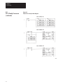
You can connect a T30 Industrial Terminal to the BASIC Module program
port to act as a dumb terminal.
Refer to the following figure 4.4 for BASIC Module/T30 connections.
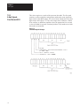
Figure 4.4
Connecting a T30 Industrial Terminal to a BASIC Module
Important: Jumper T30 Industrial Terminal pin 4,5 and 6; and BASIC
Module pins 4 and 5 if you do not use them.
4.3.4
Connecting a T50 Industrial
Terminal (Cat. No. 1784-T50)
to the Program Port
You can use your T50 Industrial Terminal as a BASIC Module
programming device. You must use a terminal driver package to configure
the industrial terminal serial port and communications protocol to match
the BASIC Module.
These packages include the ability to upload to and download from the
hard or floppy disk drives in the industrial terminal.
To upload and download you must:
4–6
1.
configure the software.
2.
construct a cable with the pin connections shown in figure 4.5 under,
“Wiring”.
3.
use the upload and download commands of the driver package.
Chapter 4
Using the Serial Ports
4.3.4
Connecting a T50 Industrial
Terminal (Cat. No. 1784-T50)
to the Program Port
(continued)
4.3.4.1
Configuring the Software
Configure the driver package for compatibility with the BASIC Module by
setting:
baud rate – 9600 baud recommended
parity – none
data bits – 8
start bits – 1
stop bits – 1
To download to the BASIC Module, you must use a line wait function. The
industrial terminal waits for the “u” BASIC Module prompt before
sending the next line to the module. You must enter a line delay of 1.5
seconds for terminal drivers that do not have the “wait for character”
function, so that you do not lose subsequent lines. Most drivers allow
storage of the complete set of parameters in a file for later recall.
The industrial terminal stores the BASIC Module program in a text file on
the hard or floppy disc depending on where you store the terminal driver
package. We recommend you store the driver package on the hard drive to
increase execution speed. Most driver packages have upload and download
capability. Refer to the driver documentation for these commands.
4.3.4.2
Wiring
Figure 4.5
Connecting a T50 Industrial Terminal to a BASIC Module
4–7
Chapter 4
Using the Serial Ports
4.4
Peripheral Port
The peripheral port is an asynchronous serial communication channel
compatible with RS-423A/232C or RS-422 interfaces. It uses bi-directional
XON/XOFF software handshaking and RTS/CTS, DTR, DSR, DCD
hardware handshaking for interfacing with printers, terminals and
commercial asynchronous modems. Use a CALL routine to change
peripheral port configuration. Configure the baud rate (300 to 19.2K bps)
by setting a configuration plug. Refer to figure 3.2 for configuration plug
locations.
In addition, the peripheral port has the following format requirements:
configurable parity: odd, even or none
fixed start bits: 1
configurable stop bits: 1, 1.5 or 2
configurable data bits: 5,6,7 or 8
receiver threshold: 200 mV
driver output (loaded): +3.6V
Defaults are 1 start bit, 1 stop bit, 8 bits/character, no parity, handshaking
off and 1200 baud.
When you select 8 bits/character you have full access to all 8 bits of each
character on both input and output data bytes.
Refer to figure 4.2 for peripheral port wiring connections.
The peripheral port can connect to printers (figure 4.6), asynchronous
modems and to SA/SB recorders for program storage and retrieval (figure
4.7).
Figure 4.6
Cable Connection to 1771-HC Printer
4–8
Chapter 4
Using the Serial Ports
4.4
Peripheral Port
(continued)
4.4.1
Using the XON/XOFF
Commands for the
Peripheral Port
Figure 4.7
Cable Connection to SA/SB Recorder
Output Data – The BASIC Module stops sending characters within 2
character times after receiving an XOFF. Transmission resumes when
XON is received.
Input Data – The BASIC Module sends XOFF when the input buffer
reaches 224 characters. The module sends XON when the buffer contains
less than 127 characters.
The BASIC Module requires CTS (pin 5) to be true before data can be
output. If hardware handshaking is not used with your device then RTS
(pin 4) may be connected to CTS to satisfy this requirement. Jumper pin 4
to pin 5.
4.4.2
Connecting A T30 Industrial
Terminal (1784-T30) to the
Peripheral Port
Communication between a programmable controller and the T30 Industrial
Terminal using the BASIC Module requires two data transfers. We use
block-transfer-read and write instructions for bi-directional data transfer
between the programmable controller data table and the BASIC Module.
We use an RS-423/RS-232 communication link for bi-directional data
transfer between the BASIC Module and the industrial terminal. Refer to
the Plant Floor Terminal Application Data (publication number 1784-4.1)
for more information.
4–9
Chapter 4
Using the Serial Ports
4.4.2
Connecting A T30 Industrial
Terminal (1784-T30) to the
Peripheral Port (continued)
4.4.2.1
Hardware Configuration
You must configure the BASIC Module peripheral port and the T30
Industrial Terminal serial port in the same way for proper communications
to occur. We configure the peripheral port on the BASIC Module as
follows:
Baud rate
1200 bps
Parity
disabled
Duplex
full (default setting)
Bits per character
8
Stop bits
1
Handshaking
disabled
Configure the T30 Industrial Terminal serial port the same way.
Refer to the following figure 4.8 for T30 Serial Port/BASIC Module
Peripheral Port connections.
Figure 4.8
T30 Serial Port/BASIC Module Peripheral Port Connections
Important: Jumper the T30 Industrial Terminal and BASIC Module pins
4 and 5 if you do not use them.
4–10
Chapter 4
Using the Serial Ports
4.4.3
Connecting a 1770-SA/SB
Recorder to the Peripheral
Port
You can use a 1770-SB Data Cartridge Recorder or 1770-SA Digital
Cassette Recorder to save and load BASIC programs to the BASIC
Module. Figure 4.6 shows cable pin connections. Use the connections
shown in figure 4.6 otherwise improper operation could occur. Note that
the standard cable does not connect properly with the BASIC Module.
Refer to the user manuals for the 1770-SB (publication number
1770-6.5.4) and 1770-SA (publication number 1770-6.5.1) for more
information on these recorders.
It is not necessary to set the peripheral port parameters (except baud rate)
before CALLing the recorder interface routines. This is done automatically
by the software. The parameters are returned to their original state when
the routine is complete.
You can find more information on saving and loading programs in Chapter
6 of this manual.
Important: STR LINK II and III Recorders do not function like SA/SB
recorders. Do not use them with the BASIC Module.
4.4.4
Connecting a 1770-HC
Printer to the Peripheral Port
You can connect a 1770-HC Printer to the peripheral port for program
listing, report generation etc. Figure 4.7 shows cable pin connections.
Refer to your printer product manual for more information.
We recommend enabling XON/XOFF on the peripheral port (see Chapter 5
section titled, “Peripheral Port Support – Parameter Set”) and selecting
XON/XOFF(DEC) protocol on the 1770-HC Printer (switch selectable).
Refer to your printer manual. You can find more information on printing
reports and listing programs in Chapter 5 of this manual.
4.4.5
Connecting RS-422 Devices
The BASIC Module can communicate with various RS-422 devices.
RS-422 signals for both sending and receiving data are located on the
module’s peripheral port. Figure 4.9 shows point-to-point signal
connections. The RS-422 port floats (i.e no voltages are applied to the
output) when it is not sending characters. This allows you to connect two
transmitting devices on the same line. Also, you can connect more than one
device in a multi-drop configuration (figure 4.10).
4–11
Chapter 4
Using the Serial Ports
4.4.5
Connecting RS-422 Devices
(continued)
Figure 4.9
Point-to-Point RS-422 Connections
Figure 4.10
Multi-drop configuration with master and multiple slaves
Important: When you use the peripheral port as a 422 port, you must
connect pin 4 to pin 5 on the port.
When using an RS-422 interface you must install termination resistors at
each end of the line. The module has a jumper selectable termination
resistor (Refer to figure 3.2). Use a cable with 2 twisted pairs and a
nominal impedance of 100 ohms.
Important: Use terminating resistors only at the ends of the link if using
multiple RS-422 devices, and at both ends if using point-to-point
connections.
4–12
Chapter 4
Using the Serial Ports
4.5
Cable Assembly Parts
You must supply cables for connecting devices to the program and
peripheral ports. You can construct the cables with the parts listed in Table
4–1.
Table 4–1
Cable assembly parts for connection to the program and
peripheral ports
Part
Manufacturer’s Part Number
25 pin female connector
Cannon type DB-25S, or equivalent
25 pin male connector
Cannon type DB-25P, or equivalent
Plastic Hood
Amp type 205718-1
2 twisted pair 22 gauge,
individually shielded cable
Cat. No. 1778-CR, Belden 8723 or equivalent (Do not use for
cable RS-422 connections)
4–13
Chapter 5
Operating Functions
5.1
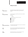
Chapter Objectives
After reading this chapter you should be familiar with the BASIC
instruction set and be ready to begin BASIC programming. This chapter
is a reference section to help you with module programming. You
should already be familiar with BASIC programming.
5.2
Definition of Terms
The following sections define the following terms: commands, statements,
format statements, data format, integers, constants, operators,
variables, expressions, relational expressions, system control values,
argument stack and control stack.
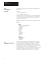
5.2.1
Commands
The BASIC module operates in two modes, the command or direct
mode and the interpreter or run mode. You can only enter commands
when the processor is in the command or direct mode. This document
uses the terms run mode and command mode to refer to the two
different operation modes.
5.2.2
Statements
A BASIC program consists of statements. Every statement begins with
a line number, followed by a statement body, and terminated with a
carriage return (cr), or a colon (:) in the case of multiple statements per
line. There are three types of statements: assignments, input/output and
control.
Every line in a program must have a statement line number ranging
between 0 and 65535 inclusive. BASIC uses this to order the
program statements in sequence.
You can use a statement number only
BASIC automatically orders
once in a program.
statements in ascending order.
A statement may not contain more than 79 characters.
BASIC ignores blanks (spaces) and automatically inserts them during
a LIST command.
Chapter 5
Operating Functions
5.2.2
Statements (continued)
You may put more than one statement on a line, if separated by a
colon (:). You can use only one statement number per line.
You can enter lower case characters in the COMMAND mode. Any
keywords, commands, variable and array names entered in lower case
change to upper case when stored in memory.
5.2.3
Format Statements
You can use format statements within the print statement. The format
statements include TAB( (|expr|), SPC([expr]), USING(special
symbols), and CR (carriage return with no line feed).
5.2.4
Data Format
You can represent the following range of numbers in
+1E–127 to +.99999999E+127
the BASIC module:
There are eight significant digits. Numbers are internally rounded
to fit this precision. You can enter and display numbers in four
formats: integer, decimal, hexadecimal and exponential.
Example:
5.2.5
Integers
129, 34.98, 0A6EH, 1.23456E+3
In the BASIC module, integers are numbers that range from 0 to 65
535 or OFFFFH. You can enter all integers in either decimal or
hexadecimal format. You indicate a hexadecimal number by placing the
character “H” after the number (e.g. 170H). If the hexadecimal number
begins with A – F, then it must be preceded by a zero (i.e. You must enter
A567H as OA567H). When an operator, such as .AND. requires an
integer, the BASIC module truncates the fraction portion of the number
so it fits the integer format. We refer to integers and line numbers as:
[integer] – [ln-num]
5–2
Chapter 5
Operating Functions
5.2.6
Constants
A constant is a real number that ranges from +1E–127 to +.9999999
9E+127. A constant can be an integer. We refer to constants as: [const]
5.2.7
Operators
An operator performs a predefined operation on variables and/or
constants. Operators require either one or two operands. Typical two
operand or dyadic operators include ADD (+), SUBTRACT (–),
MULTIPLY (*) and DIVIDE(/). We call operators that require only
one operand, unary operators. Some typical unary operators are SIN,
COS and ABS.
5.2.8
Variables
A variable can be:
a letter (e.g. A, X,I)
a letter followed by a one dimensioned expression, (e.g. J(4), GA(A +
6), I(10*SIN(X))
a letter followed by a number followed by a one dimensioned
expression (e.g. A1(8), P7(10*SIN(X)), W8(A + B).
a letter followed by a number or letter (e.g. AA, AC, XX, A1, X3,
G8) except for the following combinations: CR, DO, lE, IF, IP,
ON, PI, SP, TO, UI and UO.
We refer to variables that include a one dimensioned expression [expr] as
dimensioned or arrayed variables. We refer to variables that contain a
letter or a letter and a number as scalar variables. Any variables entered
in lower case are changed to upper case. We refer to variables as:
[var].
The BASIC module allocates variables in a “static” manner. This
means that the first time a variable is used, BASIC allocates a portion
of memory (8 bytes) specifically for that variable. This memory cannot
be de-allocated on a variable to variable basis. This means that if you
execute a statement (e.g. Q 3), you cannot tell BASIC that the
variable Q no longer exists to “free up” the 8 bytes of memory that
belong to Q. You can clear the memory allocated to variables by
executing a CLEAR statement. The CLEAR statement “frees” all
memory allocated to variables.
5–3
Chapter 5
Operating Functions
5.2.8
Variables (continued)
Important: The BASIC Module requires less time to find a scalar
variable because there is no expression to evaluate. If you want to run a
program as fast as possible, use dimensioned variables only when
necessary. Use scalars for intermediate variables and assign the final
result to a dimensioned variable. Also, put the most frequently used
variables first. Variables defined first require the least amount of time
to locate.
5.2.9
Expressions
An expression is a logical mathematical expression that involves
operators (both unary and dyadic), constants and variables. Expressions
are simple or complex, (e.g. 12*EXP(A)/100, H(1) + 55, or
(SIN(A)*SIN(A)+COS(A)* COS(A)/2). A “stand alone” variable [var]
or constant [const] is also considered an expression. We refer to
expressions as:
[expr].
5.2.10
Relational Expressions
Relational expressions involve the operators EQUAL (=), NOT
EQUAL (tu), GREATER THAN OR EQUAL TO (u=), and
LESS THAN OR EQUAL TO (t=). You use them in control statements
to test a condition (i.e. IF A t100 THEN...). Relational expressions
always require two operands. We refer to relational expressions as:
[rel expr].
5.2.11
System Control Values
The system control values include the following:
LEN (returns the length of your program).
MTOP (the last memory location assigned to BASIC).
See the following Section 5.6.2
more information.
5–4
titled, “System Control Values” for
Chapter 5
Operating Functions
5.2.12
Argument Stack
The argument stack (A-stack) stores all constants that the BASIC Module
is currently using. Operations such as add, subtract, multiply and divide
always operate on the first two numbers on the argument stack and
return the result to the stack. The argument stack is 203 bytes long.
Each floating point number placed on the stack requires 6 bytes of
storage. The argument stack can hold up to 33 floating point numbers
before overflowing.
5.2.13
Control Stack
The control stack (C-stack) stores all information associated with loop
control (i.e. DO-WHILE, DO-UNTIL, FOR-NEXT, BASIC subroutines
and “PUSHed” or “POPed” values). The control stack is 157 bytes long.
DO-WHILE and DO-UNTIL loops use 3 bytes of control stack.
FOR-NEXT loops use 17 bytes. The control stack contains enough
space for up to 9 nestings of control loops.
5–5
Chapter 5
Operating Functions
5.3
Description of Commands
The following sections list and describe the commands you can
use with the BASIC Module.
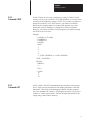
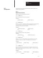
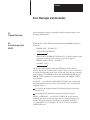
5.3.1
Command: RUN
Action Taken: After you type RUN, all variables are set equal to
zero, all BASIC evoked interrupts are cleared and program
execution begins with the first line number of the selected program. The
RUN command and the GOTO statement are the only way you can place
the BASIC Module interpreter into the RUN mode from the
COMMAND mode. You can terminate program execution at any time by
typing a Control C on the console device.
Variations: Some BASIC interpreters allow a line number to follow the
RUN command (i.e. RUN 100). The BASIC Module does not permit
this variation on the RUN command. Execution begins with the first line
number. To obtain a function similar to the RUN[ln num] command, use
the GOTO[ln num] statement in the direct mode. See statement
GOTO.
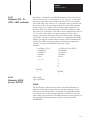
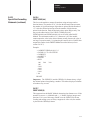
Example:
u10 FOR I=1 TO 3
u20 PRINT I
u30 NEXT I
u40 END
uRUN
1
2
3
READY
u
5–6
Chapter 5
Operating Functions
5.3.2
Command: CONT
Action Taken: If you stop a program by typing a Control C on the
console device or by execution of a STOP statement, you can resume
execution of the program by typing CONT. If you enter a Control C
during the execution of a CALL routine you cannot CONTinue.
Between the stopping and the re-starting of the program you may
display the values of variables or change the values of variables.
However, you cannot CONTinue if the program is modified during
the STOP or after an error.
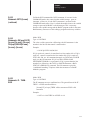
Example:
u10 FOR I=1 TO 10000
u20 PRINT I
u30 PRINT I
u40 END
uRUN
1
2
3
4
5– (TYPE CONTROL C ON CONSOLE)
STOP – IN LINE 20
READY
uPRINT I
6
uI=10
uCONT
10
11
12
5.3.3
Command: LIST
Action taken: The LIST command prints the program to the console
device. Spaces are inserted after the line number, and before and after
statements. This helps in the debugging of BASIC Module programs.
You can terminate the “listing” of a program at anytime by typing a
Control C on the console device. You can interrupt and continue the
listing using Control S and Control Q.
5–7
Chapter 5
Operating Functions
5.3.3
Command: LIST
(continued)
Variations: Two variations of the LIST command are possible with the
BASIC Module.
They are:
1. LIST [ln num] (cr)
and
2. LIST [ln num] – [ln num] (cr)
The first variation causes the program to print from the designated
line number (integer) to the end of the program. The second variation
causes the program to print from the first line number (integer) to the
second line number (integer).
Important: You must separate the two line
(–).
numbers with a dash
Example:
READY
uLIST
u10 PRINT “LOOP PROGRAM”
u20 FOR I=1 TO 3
u30 PRINT I
u40 NEXT I
u50 END
READY
uLIST 30
u30 PRINT I
u40 NEXT I
u50 END
READY
uLIST 20–40
u20 FOR I=1 TO 3
u30 PRINT I
u40 NEXT I
5.3.4
Command: LIST# or LIST
5–8
Action taken: The LIST# or LIST@ command lists the program to
the device attached to the peripheral port (LIST device). All comments
that apply to the LIST command apply to the LIST# or LIST@
commands. We include these commands to permit you to make “hard
copy printouts” of a program. A configuration plug sets the baud
rate and must match your list device (see section 3.2.4 titled,
“Configuration Plugs”). Also, you must configure the peripheral port
parameters to match your particular list device (see section 5.8.1
titled, “Peripheral Port Support – Parameter Set – CALL 30”).
Chapter 5
Operating Functions
5.3.5
Command: NEW
Action taken: When you enter NEW(cr), the BASIC Module deletes
the program that is currently stored in RAM memory. In addition, all
variables are set equal to ZERO, all strings and all BASIC evoked
interrupts are cleared. The REAL TIME CLOCK, string allocation, and
the internal stack pointer values are not affected. In general, NEW (cr) is
used to erase a program and all variables.
5.3.6
Command: NULL [integer]
Action taken: The NULL[integer] command determines how many
NULL characters (00H) the BASIC Module outputs after a carriage
return. After initialization NULL 0. Most printers contain a RAM
buffer that eliminates the need to output NULL characters after a carriage
return.
5.3.7
Command: Control C
Action taken: This command stops execution of the current program and
returns the BASIC Module to the COMMAND mode. In some cases
you can continue execution using a CONTinue. See the explanation
for CONTinue for more information.
5.3.7.1
Command: Disabling Control C
Action taken: This command disables the Control C break function.
You can do this by setting bit 48 (30H) to 1. Bit 48 is located in
internal memory location 38 (26H). Set bit 48 by executing the following
statement in a BASIC Module program or from the command mode:
DBY(38)
DBY(38).OR.01H
When bit 48 is set to 1, the Control C break function for both LIST and
RUN operations is disabled. Cycling power returns Control C to normal
operation if it is disabled from the command mode.
To re-enable the Control C function, execute the following statement in a
BASIC Module program or from the command mode.
DBY(38)
DBY(38).AND.0FEH
CALL routines do not check for this feature. If you enter a Control C
while using a CALL routine, the program stops if Control C is enabled or
disabled.
5–9
Chapter 5
Operating Functions
5.3.8
Command: Control S
Action taken: This command interrupts the scrolling of a BASIC
program during the execution of a LIST command. It also stops
output from the receiving port if you are running a program. In this
case XOFF (Control S) operates as follows:
1. XOFF only operates on PRINT statements.
2. When received during a PRINT, data output and program execution
are suspended immediately.
3. When received at any other time, program execution continues until a
PRINT is encountered. At this time program execution is suspended.
4. XON (Control Q) is required
to resume program operation.
5.3.9
Command: Control Q
Action taken: This command restarts a LIST command or PRINT output
that is interrupted by a Control S.
5.3.10
Overview of EPROM File
Commands
Your BASIC Module can execute and SAVE up to 255 programs in
an EPROM. The module generates all of the timing signals
needed to program most EPROM devices. The programs are stored
in sequence in the EPROM for retrieval and execution. This sequential
storing of programs is called the EPROM FILE. The following
commands allow you to generate and manipulate the EPROM
FILE.
5.3.11
Commands: RAM and ROM
[integer]
Action taken: These two commands tell the the BASIC Module
interpreter whether to select the current program out of RAM or EPROM.
The current program is displayed during a LIST command and
executed when RUN is typed.
5–10
Chapter 5
Operating Functions
5.3.11
Commands: RAM and ROM
[integer] (continued)
5.3.11.1 RAM
When you enter RAM(cr), the BASIC Module selects the current
program from RAM MEMORY.
Important: RAM space is limited to 13 K bytes. Use the following
formula to calculate the available user RAM space:
LEN system control
program length
value which contains current
+# bytes allocated for strings
instruction)
(first
RAM
value in the STRING
+6 * each array size + 1 (asterisk = multiply)
+8 * each variable used (including each array name)
+1024 – number of bytes reserved for BASIC
V
Available user RAM= MTOP–V
5.3.11.2 ROM
When you enter ROM [integer], the BASIC Module selects the current
program out of EPROM memory. If no integer is typed after the
ROM command (i.e. ROM) the module defaults to ROM 1. Since the
programs are stored in sequence in EPROM, the integer following
the ROM command selects which program the user wants to run or
list. If you attempt to select a program that does not exist (e.g. you type
in ROM 8 and only 6 programs are stored in the EPROM) the
message ERROR: PROM MODE is displayed.
The module does not transfer the program from EPROM to RAM when
the ROM mode is selected. If you attempt to alter a program in
the ROM mode, by typing in a line number, the message ERROR:
PROM MODE displays. The XFER command allows you to transfer
a program from EPROM to RAM for editing purposes. You get no
error message if you attempt to edit a line of ROM program.
Important: When you transfer programs from EPROM to RAM you
lose the previous RAM contents.
Since the ROM command does NOT transfer a program to RAM, it is
possible to have different programs in ROM and RAM simultaneously.
You can move back and forth between the two modes when in
command mode. If you are in run mode you can change back and forth
using CALLS 70, 71 and 72. You can also use all of the RAM memory
for variable storage if the program is stored in EPROM. The system
control value – MTOP always refers to RAM. The system control value,
LEN, refers to the currently selected program in RAM or ROM.
5–11
Chapter 5
Operating Functions
5.3.12
Command: XFER
Action taken: The XFER (transfer) command transfers the current
selected program in EPROM to RAM and then selects the RAM
mode. If you type XFER while the BASIC Module is in the RAM
mode, the program stored in RAM is transferred back into RAM
and the RAM mode is selected. After the XFER command
executes, you can edit the program in the same way you edit any RAM
program.
Important: The XFER command clears existing RAM programs.
5.3.13
Command: PROG
Important: Before you attempt to program a PROM, read the PROG,
PROG1 and PROG2 sections of this chapter. Some PROG options
exclude the use of others.
Action taken: The PROG command programs the resident EPROM
with the current program. The current selected program may reside in
either RAM or EPROM. See Section 3.4, titled “Installing the User
Prom”, for additional information concerning EPROM’s.
Important: Be sure you have selected the program you want to save
before using the PROG command. Your module does not automatically
copy the RAM program to ROM. You must also disable interrupts prior
to the PROG, PROG1 or PROG2 commands using CALL 8 and
enable interrupts after the PROM is burned using CALL 9. If an
error occurs during EPROM programming, the message ERROR
PROGRAMMING is displayed. When this error occurs:
previously stored programs may or may not be accessible.
you cannot store additional programs on this PROM.
After you type PROG(cr), the BASIC Module displays the number in
the EPROM FILE the program occupies. Programming can take
up to 12 minutes to complete depending on the length of the program
(51 seconds per K bytes of program).
5–12
Chapter 5
Operating Functions
5.3.13
Command: PROG
(continued)
Example:
uLIST
10 FOR I=1 TO 10
20 PRINT I
30 NEXT I
40 END
READY
uCALL 8 :REM DISABLE INTERRUPTS
uPROG
12
uREADY CALL 9 :REM ENABLE INTERRUPTS
uROM 12
READY
uLIST 10 FOR I=1 TO 10
20 PRINT I
30 NEXT I
40 END
READY
u
In this example, the program just placed in the EPROM is the 12th
program stored.
Important: If you exceed the available PROM space, you cannot
continue programming until it is erased. In some cases you can alter the
previously stored programs. Be sure to use CALL 81 to determine
memory space prior to burning. See section 5.3.13.1 below.
5.3.13.1 User PROM Check
and
Description – CALL 81
Use CALL 81 in command mode before burning a program into
PROM memory. This CALL:
determines the number of PROM programs.
determines the number of bytes left in PROM.
determines the number of bytes in the RAM program.
prints a message telling if enough space is available in PROM for
the RAM program.
checks for
a valid PROM if it contains no program.
prints a good or bad PROM message. A bad PROM message with
an address of 00xx indicates an incomplete program.
No PUSHes or POPs are needed.
5–13
Chapter 5
Operating Functions
5.3.14
Command: PROG1
Action taken: You can use the PROG1 command to program the
resident EPROM with baud rate information. When the module is
“powered-up” the module reads this information and initializes the
program port with the stored baud rate. The “sign-on” message is sent to
the console immediately after the module completes its reset
sequence. If the baud rate on the console device is changed you must
program a new EPROM to make the module compatible with the new
console.
If you have already used a PROG2 command, you cannot use the
PROG 1 command.
5.3.15
Command: PROG2
Action taken: The PROG2 command functions the same as the
PROG1 command except for the following. Instead of “signing-on” and
entering the command mode, the module immediately begins executing
the first program stored in the resident EPROM, if no program is stored
in RAM. Otherwise it executes the RAM program. You can use the
PROG2 command to RUN a program on power-up without connecting to
a console. Saving PROG2 information is the same as typing a ROM 1,
RUN command sequence. This feature also allows you to write a special
initialization sequence in BASIC and generate a custom “sign-on”
message for specific applications.
If you have already used a PROG1 command,
PROG 2 command.
5–14
you cannot use the
Chapter 5
Operating Functions
5.3.15
Command: PROG2
(continued)
Figure 5.1
Flow Chart of Power-up Operation
Figure 5.1 shows BASIC Module operation from a power-up condition
using PROG1 or PROG2; or battery backed RAM.
5–15
Chapter 5
Operating Functions
5.4
Description of Statements
The following sections list and describe the statements you can use
with the BASIC Module.
5.4.1
Statement: CALL [integer]
Mode: COMMAND AND/ OR RUN
Type: CONTROL
You use the CALL [integer] statement to call specially written BASIC
Module application programs. Specific call numbers are defined later
in this chapter.
5.4.2
Statement: CLEAR
Mode: COMMAND AND/OR RUN
Type: CONTROL
The CLEAR statement sets all variables equal to 0 and resets all
BASIC evoked interrupts and stacks. This means that after the CLEAR
statement is executed an ONTIME statement must be executed before the
module acknowledges the internal timer interrupts. ERROR trapping
using the ONE RR statement also does not occur until an
ONERR[integer] statement is executed. The CLEAR statement does
not affect the real time clock that is enabled by the CLOCK1
statement. CLEAR also does not reset the memory that has been
allocated for strings, so it is not necessary to enter the STRING
[expr], [expr] statement to re-allocate memory for strings after the
CLEAR statement is executed. In general, CLEAR is used to
“erase” all variables.
5.4.3
Statement: CLEARI
(clear interrupts)
Mode: COMMAND AND/OR RUN
Type: CONTROL
The CLEARI statement clears all of the BASIC evoked interrupts. The
ONTIME interrupt disables after the CLEARI statement executes.
CLEARI does not affect the real time clock enabled by the CLOCK1
statement. You can use this statement to selectively DISABLE
ONTIME interrupts during specific sections of your BASIC program.
You must execute the ONTIME statement again before the specific
interrupts enable.
Important: When the CLEARI statement is LISTED it appears as
CLEAR I.
5–16
Chapter 5
Operating Functions
5.4.4
Statement: CLEARS
Mode: COMMAND/RUN
Type: CONTROL
The CLEARS statement resets all of the module’s stacks. The
control, argument and internal stacks all reset to their initialization
values. You can use this command to reset the stack if an error occurs
in a subroutine.
Important: When the CLEARS statement is LISTed it appears as
CLEAR S.
5.4.5
Statements: CLOCK1
and CLOCK0
Mode: COMMAND AND/OR RUN
Type: CONTROL
CLOCK1
The CLOCK1 statement enables the real time clock feature resident
on the BASIC Module. The special function operator TIME is
incremented once every 5 milliseconds after the CLOCK1 statement is
executed. The CLOCK1 STATEMENT uses an internal TIMER to
generate an interrupt once every 5 milliseconds. Because of this, the
special function operator TIME has a resolution of 5 milliseconds.
The special function operator TIME counts from 0 to 65535.995
seconds. After reaching a count of 65535.995 seconds TIME
overflows back to a count of zero. The interrupts associated with the
CLOCK1 statement cause the module programs to run at about 99.6%
of normal speed. That means that the interrupt handling for the REAL
TIME CLOCK feature uses about .4% of the total CPU time.
CLOCK0
The CLOCK0 (zero) statement disables or “turns off” the real time
clock feature. After CLOCK0 is executed, the special function operator
TIME no longer increments. CLOCK0 is the only module statement
that can disable the real time clock. CLEAR and CLEARI do NOT
disable the real time clock, only its associated ONTIME interrupt.
Important: CLOCK1 and CLOCK0 are independent of the wall
clock.
5–17
Chapter 5
Operating Functions
5.4.6
Statements: DATA –
READ – RESTORE
Mode: RUN
Type: Assignment
DATA
DATA specifies expressions that you can retrieve using a READ statement.
If multiple expressions per line are used, you MUST separate them with a
comma.
Example:
u10 DATA 10,ASC(A), ASC(B), 35.627
Important: You cannot use the CHR() operator in a DATA statement.
READ
READ retrieves the expressions that are specified in the DATA statement
and assigns the value of the expression to the variable in the READ
statement. The READ statement is always followed by one or more
variables. If more than one variable follows a READ statement, they
are separated by a comma.
RESTORE
RESTORE “resets” the internal read pointer to the beginning of the
data so that it may be read again.
Example:
u10 FOR I=1 TO 3
u20 READ A,B
u30 PRINT A,B
u40 NEXT I
u50 RESTORE
u60 READ A,B
u70 PRINT A,B
u80 DATA 10,20, 10/2,20/2,SIN(PI),COS(PI)
uRUN
10
5
0
10
20
10
–1
20
Every time a READ statement is encountered the next consecutive
expression in the DATA statement is evaluated and assigned to the
variable in the READ statement. You can place DATA statements
anywhere within a program. They are not executed and do not cause an
error. DATA statements are considered to be chained together and appear
to be one large DATA statement. If at anytime all the data is read and
another READ statement is executed, the program terminates and the
message ERROR: NO DATA – IN LINE XX prints to the console
device.
5–18
Chapter 5
Operating Functions
5.4.7
Statement: DIM
Mode: COMMAND AND/OR RUN
Type: Assignment
DIM reserves storage for matrices. The storage area is first assumed to
be zero. Matrices in the BASIC Module may have only one
dimension and the size of the dimensioned array may not exceed 254
elements. Once a variable is dimensioned in a program it may not be
re-dimensioned. An attempt to re-dimension an array causes an
ARRAY SIZE ERROR. If an arrayed variable is used that is not
dimensioned by the DIM statement, BASIC assigns a default value of
10 to the array size. All arrays are set equal to zero when the RUN
command, NEW command or the CLEAR statement is executed. The
number of bytes allocated for an array is 6 times the array size plus 1.
The array A(100) requires 606 bytes of storage. Memory size usually
limits the size of a dimensioned array.
Variations: More than one variable can be dimensioned by a single
DIM statement.
Example:
u10 DIM A(25), B(15), A1(20)
Example: Default error on attempt to re-dimension array
u10 A(5)10 –BASIC ASSIGNS DEFAULT OF 10 TO ARRAY SIZE HERE
u20 DIM A(5) –ARRAY CANNOT BE RE–DIMENSIONED
uRUN
ERROR: ARRAY SIZE – IN LINE 20
20
DIM A(5)
-
X
5.4.8
Statements: DO – UNTIL
[rel expr]
Mode: RUN
Type: CONTROL
The DO – UNTIL [rel expr] instruction provides a means of “loop
control” within a module program. All statements between the DO
and the UNTIL [rel expr] are executed until the relational expression
following the UNTIL statement is TRUE. You may nest DO – UNTIL
loops.
5–19
Chapter 5
Operating Functions
5.4.8
Statements: DO – UNTIL
[rel expr] (continued)
Examples:
SIMPLE DO-UNTIL
NESTED DO-UNTIL
u10 A=0
u20 DO
u30 A=A+1
u10 DO
u20 A=A+1
u30 DO
u40 B=B+1
u50 PRINT A,B,A,*B
u60 UNTIL B=3
u70 B=0
u80 UNTIL A=3
u90 END
uRUN
u40 PRINT A
u50 UNTIL A=4
u60 PRINT “DONE”
u70 END
uRUN
1
2
3
4
DONE
READY
u
111
122
133
212
224
236
313
326
339
READY
u
5–20
Chapter 5
Operating Functions
5.4.9
Statements: DO – WHILE
[rel expr] (continued)
Mode: RUN
Type: CONTROL
The DO – WHILE [rel expr] instruction provides a means of “loop
control” within a module program. The operation of this statement is
similar to the DO – UNTIL [rel expr] except that all statements
between the DO and the WHILE [rel expr] are executed as long as the
relational expression following the WHILE statement is true. You can
nest DO – WHILE and DO – UNTIL statements.
Examples:
SIMPLE DO-WHILE
NESTED
DO-WHILE - DO-UNTIL
u10 DO
u20 A=A+1
u30 PRINT A
u40 WHILE At4
u50 PRINT “DONE”
u60 END
uRUN
u10 DO
u20 PRINT A=A+1
u25 DO
u30 B=B+1
u40 A,B,A*B
u50 WHILE Btu3
u60 B=0
u70 UNTIL A=3
u80 END
uRUN
111
122
133
212
224
236
313
326
339
1
2
3
4
DONE
READY
u
READY
u
5–21
Chapter 5
Operating Functions
5.4.10
Statement: END
Mode: RUN
Type: CONTROL
The END statement terminates program execution. The continue comm
and, CONT does not operate if the END statement is used to
terminate execution. A CAN’T CONTINUE ERROR prints to the console.
The last statement in a module program automatically terminates
program execution if you do not use an end statement. You should
always use an END statement to terminate a program.
Examples:
END STATEMENT TERMINATION
u10 FOR I=1 TO 4
u20 GOSUB 100
u30 NEXT I
u40 END
u100 PRINT I
u110 RETURN
uRUN
1
2
3
4
READY
u
Variations: None
5.4.11
Statements: FOR – TO –
(STEP) – NEXT
Mode: RUN
Type: CONTROL
Use the FOR – TO – (STEP) – NEXT statements to set up and control
loops.
Example:
u5 B=0: C=10 : D=2
u10 FOR A= B TO C STEP D
u20 PRINT A
u30 NEXT A
u40 END
5–22
Chapter 5
Operating Functions
5.4.11
Statements: FOR – TO –
(STEP) – NEXT (continued)
Since B=0, C=10 and D=2, the PRINT statement at line 20 executes
6 times. The values of “A” printed are 0, 2, 4, 6, 8 and 10. “A” represents
the name of the index or loop counter. The value of “B” is the starting
value of the index. The value of “C” is the limit value of the index and
the value of “D” is the increment to the index. If the STEP statement
and the value “D” are omitted, the increment value defaults to 1,
therefore, STEP is an optional statement. The NEXT statement adds
the value of “D” to the index. The index is then compared to the value of
“C”, the limit. If the index is less than or equal to the limit, control
transfers back to the statement after the FOR statement. Stepping
“backwards” (FOR I= 100 TO 1 STEP–1) is permitted in the BASIC
Module. You may not omit the index from the NEXT statement in the
module (The NEXT statement is always followed by the appropriate
variable). You may nest FOR-NEXT loops up to 9 times.
Examples:
u10 FOR I=1 TO 4
u20 PRINT I,
u30 NEXT I
u40 END
uRUN
1234
READY
u
5.4.12
Statements: GOSUB
[ln num] – RETURN
u10 FOR I=O TO 8 STEP 2
u20 PRINT I
u30 NEXT I
u40 END
uRUN
0
2
4
6
8
READY
u
Mode: RUN
Type: CONTROL
GOSUB
The GO SUB [ln num] statement causes the BASIC Module to
transfer control of the program directly to the line number ([ln num])
following the GOSUB statement. In addition, the GOSUB statement
saves the location of the statement following GOSUB on the control
stack so that you can perform a RETURN statement to return control to
the statement following the most recently executed GO SUB
STATEMENT.
5–23
Chapter 5
Operating Functions
5.4.12
Statements: GOSUB [ln num]
– RETURN (continued)
RETURN
Use this statement to “return” control to the statement following the
most recently executed GO SUB STATEMENT. Use one return for each
GOSUB to avoid overflowing the C-STACK. This means that a
subroutine called by the GO SUB statement can call another
subroutine with another GOSUB statement.
Examples:
SIMPLE SUBROUTINE NESTED SUBROUTINES
u10 FOR I=1 TO 5
u20 GOSUB 100
u30 NEXT I
u40 END
u100 PRINT I
u110 RETURN
uRUN
1
2
3
4
5
READY
u
u10 FOR I=1 TO 3
u20 GOSUB 100
u30 NEXT I
u40 END
u100 REM USER SUBROUTINE HERE
u105 PRINT I,
u110 GOSUB 200
u200 PRINT I,I*I
u210 RETURN
uRUN
1 1
2 4
3 9
READY
u
5.4.13
Statement: GOTO [ln num]
Mode: COMMAND AND/OR RUN
Type: CONTROL
The GOTO [ln num] statement causes BASIC to transfer control directly
to the line number ([ln num]) following the GOTO statement.
Example:
u50 GOTO 100
If line 100 exists, this statement causes execution of the program to
resume at line 100. If line number 100 does not exist the message ERROR:
INVALID LINE NUMBER is printed to the console device.
5–24
Chapter 5
Operating Functions
5.4.13
Statement: GOTO [ln num]
(continued)
Unlike the RUN command the GOTO statement, if executed in the
COMMAND mode, does not clear the variable storage space or
interrupts. However, if the GOTO statement is executed in the
COMMAND mode after a line is edited the module clears the variable
storage space and all BASIC evoked interrupts. This is necessary
because the variable storage and the BASIC program reside in the same
RAM memory. Because of this editing a program can destroy variables.
5.4.14
Statements: ON [expr] GOTO
[ln num], [ln num],...[ln num],
ON [expr] GOSUB[ln num],
[ln num],...[ln num]
Mode: RUN
Type: CONTROL
The value of the expression following the ON statement is the
number in the line list that control is transferred to.
Example:
u10 ON Q GOTO 100,200,300
If Q is equal to 0, control is transferred to line number 100. If Q is
equal to 1, control is transferred to line number 200. If Q is equal to 2,
GOTO line 300, etc. All comments that apply to GOTO and GOSUB
apply to the ON statement. If Q is less than ZERO a BAD
ARGUMENT ERROR is generated. If Q is greater than the line
number list following the GOTO or GOSUB statement, a BAD
SYNTAX ERROR is generated. The ON statement provides
“conditional branching” options within the constructs of a BASIC
Module program.
5.4.15
Statements: IF – THEN –
ELSE
Mode: RUN
Type: CONTROL
The IF statement sets up a conditional test. The general form of the IF –
THEN – ELSE statement follows:
[ln num] IF [rel expr] THEN valid statement ELSE valid
statement
Example:
u10 IF A=100 THEN A=0 ELSE A=A+1
5–25
Chapter 5
Operating Functions
5.4.15
Statements: IF – THEN –
ELSE (continued)
Upon execution of line 10 IF A is equal to 100, THEN A is assigned a
value of 0. IF A does not equal 100, A is assigned a value of A+1. If you
want to transfer control to different line numbers using the IF
statement, you may omit the GOTO statement. The following examples
give the same results:
u20 IF INT(A)
u20 IF INT(A)
t10 THEN GOTO 100 ELSE GOTO 200
or
t10 THEN 100 ELSE 200
You can replace the THEN statement with any valid BASIC Module
statement, as shown below:
u30 IF Atu 10 THEN PRINT A ELSE 10
u30 IF Atu 10 PRINT A ELSE 10
You may execute multiple statements following the THEN or ELSE
if you use a colon to separate them.
Example:
u30 IF Atu 10 THEN PRINT A:GOTO 150 ELSE 10
u30 IF Atu 10 PRINT A:GOTO 150 ELSE 10
In these examples, if A does not equal 10 then both PRINT A and
GOTO 150 are executed. If A10, then control passes to 10.
You may omit the ELSE statement. If you omit the ELSE statement control
passes to the next statement.
Example:
u20 IF A10 THEN 40
u30 PRINT A
In this example, if A equals 10 then control passes to line number 40. If
A does not equal 10 line number 30 is executed.
5.4.16
Statement: INPUT
Mode: RUN
Type: INPUT/OUTPUT
The INPUT statement allows you to enter data from the console during
program execution. You may assign data to one or more variables with a
single input statement. You must separate the variables with a
comma.
Example:
uINPUT A,B
5–26
Chapter 5
Operating Functions
5.4.16
Statement: INPUT
(continued)
Causes a question mark (?) to print on the console device. This
prompts you to input two numbers separated by a comma. If you do
not enter enough data, the module prints TRY AGAIN on the console
device.
Example:
u10 INPUT A,B
u20 PRINT A,B
uRUN
?1
TRY AGAIN
?1,2
1 2
READY
You can write the INPUT statement so that a descriptive prompt tells
you what to enter. The message to be printed is placed in quotes after
the INPUT statement. If a comma appears before the first variable on
the input list, the question mark prompt character is not displayed.
Examples:
u10 INPUT“ENTER A NUMBER” A
u20 PRINT SQR(A)
u30 END
uRUN
u10 INPUT”ENTER A NUMBER–”,A
u20 PRINT SQR(A)
u30 END
uRUN
ENTER A NUMBER
?100
10
ENTER A NUMBER–100
10
You can also assign strings with an INPUT statement. Strings are
always terminated with a carriage return (cr). If more than one string
input is requested with a single INPUT statement, the module prompts
you with a question mark.
5–27
Chapter 5
Operating Functions
5.4.16
Statement: INPUT
(continued)
Examples:
u10 STRING 110,10
u20 INPUT “NAME:”,$(1)
u30 PRINT “HI”,$(1)
u40 END
uRUN
u10 STRING 110,10
u20 INPUT “NAMES:”,$(1),$(2)
u30 PRINT “HI”,$(1),“ AND “,$(2)
u40 END
uRUN
NAME: SUSAN
HI SUSAN
NAMES: BILL
?ANN
HI BILL AND ANN
READY
READY
You can assign strings and variables with a single INPUT statement.
Example:
u10 STRING 100,10
u20 INPUT“NAME(CR), AGE – ”,$(1),A
u30 PRINT “HELLO ”,$(1),“, YOU ARE ”,A,“YEARS OLD”
u40 END
uRUN
NAME(CR), AGE – FRED
?15
HELLO FRED, YOU ARE 15 YEARS OLD
READY
u
5.4.17
Statement: LD@ [expr]
5–28
Mode: COMMAND AND/OR RUN
This statement, along with CALL 77, allows you to save/retrieve
variables to/from a protected area of memory. This protected area is
not zeroed on power-up or when the RUN command is issued. The LD@
statement takes the variable stored at address [expr] and moves it to
the top of the argument stack. For more information on protecting
variables, see section 5.11.6, “Protected Variable Storage – CALL 77”.
Chapter 5
Operating Functions
5.4.18
Statement: LET
Mode: COMMAND AND/OR RUN
Type: ASSIGNMENT
Use the LET statement to assign a variable to the value of an
expression. The general form of LET is:
LET [var] = [expr]
Examples:
LET A =10*SIN(B)/100 or
LET A = A+1
Note that the = sign used in the LET statement is not an equality
operator. It is a “replacement” operator. The statement should be read
A is replaced by A plus one. The word LET is always optional, (i.e.
LET A =2 is the same as A =2).
When LET is omitted the LET statement is called an IMPLIED
LET. We use the word LET to refer to both the LET statement and
the IMPLIED LET statement.
Also use the LET statement to assign the string variables:
LET $(1)=“THIS IS A STRING” or
LET $(2)=$(1)
Before you can assign strings you must execute the STRING [expr],
[expr] statement or else a MEMORY ALLOCATION ERROR occurs.
See the following section 5.4.31 titled, “STRING”.
5–29
Chapter 5
Operating Functions
5.4.19
Statement: ONERR
[ln num)
Mode: RUN
Type: CONTROL
The ONERR[ln num] statement lets you handle arithmetic errors, if
they occur, during program execution. Only ARITH. OVERFLOW,
ARITH. UNDERFLOW, DIVIDE BY ZERO and BAD ARGUMENT
errors are “trapped” by the ONE RR statement. All other errors are
not “trapped”. If an arithmetic error occurs after the ONE RR
statement is executed, the module interpreter passes control to the line
number following the ONERR[ln num] statement. You handle the error
condition in a manner suitable to the particular application. The ONERR
command does not trap bad data entered during an input
instruction. This yields a “TRY AGAIN” message or “EXTRA
IGNORED” message. See Chapter 9 for an explanation of errors.
With the ONERR[ln num] statement, you have the option of
determining what type of error occurred. Do this by examining
external memory location 257 (101H) after the error condition is
trapped.
The error codes are:
ERROR CODE =10 – DIVIDE BY ZERO
ERROR CODE =20 – ARITH. OVERFLOW
ERROR CODE =30 – ARITH. UNDERFLOW
ERROR CODE =40 – BAD ARGUMENT
You can examine this location by using an XBY(257) statement.
Example:
PRINT XBY(257)
or
E XBY(257)
5–30
Chapter 5
Operating Functions
5.4.20
Statement: ONTIME
[expr],[ln num]
Mode: RUN
Type: CONTROL
Your BASIC Module can process a line in milliseconds while the
timer/counters on the microprocessor operate in microseconds. You must
use the ONTIME [expr], [In num] statement because of this
incompatibility between the timer/counters on the microprocessor and the
BASIC Module. The ONTIME statement generates an interrupt every time
the special function operator, TIME, is equal to or greater than the
expression following the ON TIME statement. Only the integer portion of
TIME is compared to the integer portion of the expression. This
comparison is performed at the end (CR or:) of each line of BASIC. The
interrupt forces a GOSUB to the line number [ln num] ) following the
expression ([expr]) in the ONTIME statement.
Important: The ONTIME statement does not interrupt an input
command or a CALL routine. Since the ONTIME statement uses the
special function operator, TIME, you must execute the CLOCK1 statement
for ONTIME to operate. If CLOCK1 is not executed the special function
operator, TIME, does not increment.
You can generate periodic interrupts by executing the ONTIME statement
again in the interrupt routine:
Example:
u10 TIME=0 : CLOCK1 : ONTIME 2,100: DO
u20 WHILE TIMEt10 : END
u100 PRINT “TIMER INTERRUPT AT –”,TIME,“SECONDS”
u110 ONTIME TIME+2,100 : RETI
uRUN
TIMER INTERRUPT AT – 2.045 SECONDS
TIMER INTERRUPT AT – 4.045 SECONDS
TIMER INTERRUPT AT – 6.045 SECONDS
TIMER INTERRUPT AT – 8.045 SECONDS
TIMER INTERRUPT AT – 10.045 SECONDS
READY
The terminal used in this example runs at 4800 baud. This baud rate allows
about 45 milliseconds to print the message TIMER INTERRUPT AT –“ ”.
The resulting printed time is 45 milliseconds greater than the planned time.
5–31
Chapter 5
Operating Functions
5.4.20
Statement: ONTIME
[expr], [ln num] (continued)
If you do not want this delay, you should assign a variable to the special
function operator, TIME, at the beginning of the interrupt routine.
Example:
u10 TIME=0 : CLOCK1 : ONTIME 2,100: DO
u20 WHILE TIME t10: END
u100 A=TIME
u110 PRINT “TIMER INTERRUPT AT –”,A,“SECONDS”
u120 ONTIME A+2,100 : RETI
uRUN
TIMER INTERRUPT AT – 2 SECONDS
TIMER INTERRUPT AT – 4 SECONDS
TIMER INTERRUPT AT – 6 SECONDS
TIMER INTERRUPT AT –8 SECONDS
TIMER INTERRUPT AT – 10 SECONDS
READY
Important: You must exit the ONTIME interrupt routine with a RET I
statement. Failure to do this “locks-out” all future interrupts.
The ONTIME statement eliminates the need for you to “test” the value of
the TIME operator periodically throughout the BASIC program.
5.4.21
Statement: PRINT or P.
Mode: COMMAND and/or RUN
Type: INPUT/OUTPUT
The PRINT statement directs the BASIC Module to output to the console
device. You may print the value of expressions, strings, literal values,
variables or text strings. You may combine the various forms in the print
list by separating them with commas. If the list is terminated with a
comma, the carriage return/line feed is suppressed. P. is a “shorthand”
notation for PRINT.
Examples:
uPRINT 10*10,3*3 u PRINT “MCS–51″ u PRINT 5,1E3
100 9
MCS–51
5 1000
Important: Values are printed next to one another with two intervening
blanks. A PRINT statement with no arguments sends a carriage return/line
feed sequence to the console device.
5–32
Chapter 5
Operating Functions
5.4.22
Special Print Formatting
Statements
The following sections list and describe the special print formatting
statements.
5.4.22.1
PRINT TAB([expr])
Use the TAB([expr]) function in the PRINT statement to cause data to print
out in exact locations on the output device. TAB([expr]) tells the BASIC
Module which position to begin printing the next value in the print list. If
the printhead or cursor is on or beyond the specified TAB position, the
module ignores the TAB function.
Example:
uPRINT TAB(5),“X”,TAB(10),“Y”
X
Y
5.4.22.2
PRINT SPC([expr])
Use the SPC([expr]) function in the PRINT statement to cause the BASIC
Module to output the number of spaces in the SPC argument.
Example:
u PRINT A,SPC(5),B
Use the above statement to place an additional 5 spaces between the A and
B in addition to the two that would normally print.
5.4.22.3
PRINT CR
Use CR in a PRINT statement to force a carriage return, but no line feed.
You can use CR to create one line on a CRT device that is repeatedly
updated.
Example:
u 10 FOR I=1 TO 1000
u20 PRINT I,CR,
u30 NEXT I
The above example causes the output to remain on one line only. No line
feed is ever sent to the console device.
5–33
Chapter 5
Operating Functions
5.4.22
Special Print Formatting
Statements (continued)
5.4.22.4
PRINT USING (special characters)
Use the USING function to tell the BASIC Module what format to use
when displaying printed values. The module “stores” the desired format
after the USING statement is executed. All outputs following a USING
statement are in the format evoked by the last USING statement executed.
You do not need to execute the USING statement within every PRINT
statement unless you want to change the format. U. is a “shorthand”
notation for USING.
Important: The USING statement applies to numbers following it until
another USING statement is encountered.
5.4.22.5
PRINT USING(Fx)
This forces the BASIC Module to output all numbers using the floating
point format. The value of x determines how many significant digits are
printed. If x equals 0, the module does not output any trailing zeros, so the
number of digits varies depending upon the number. The module always
outputs at least 3 significant digits even if x is 1 or 2. The maximum value
for x is 8.
Example:
u10 PRINT USING(F3),1,2,3
u20 PRINT USING(F4),1,2,3
u30 PRINT USING(F5),1,2,3
u40 FOR I=10 TO 40 STEP 10
u50 PRINT I
u60 NEXT I
uRUN
1.00 E 0 2.00 E 0 3.00 E 0
1.000 E 0 2.000 E 0 3.000 E 0
1.0000 E 0 2.0000 E 0 3.0000 E 0
1.0000 E+1
2.0000 E+1
3.0000 E+1
4.0000 E+1
READY
5–34
Chapter 5
Operating Functions
5.4.22
Special Print Formatting
Statements (continued)
5.4.22.6
PRINT USING(#.#)
This forces the module to output all numbers using an integer and/or
fraction format. The number of “#”’s before the decimal point represents
the number of significant integer digits that are printed and the number of
“#”’s after the decimal point represents the number of digits that are
printed in the fraction. Omit the decimal point to print integers only. You
may use the abbreviation U for USING. USING(###.###),
USING(######) and USING(######.##) are all valid in the BASIC
Module. The maximum number of “#” characters is 8. If the module
cannot output the value in the desired format (usually because the value is
too large) a question mark (?) is printed to the console device. BASIC then
outputs the number in the FREE FORMAT described below (refer to
section 5.4.22.7).
Example:
u10 PRINT USING(##.##),1,2,3
u20 FOR I=1 TO 120 STEP 20
u30 PRINT I
u40 NEXT I
u50 END
uRUN
1.00
2.00
3.00
1.00
21.00
41.00
61.00
81.00
? 101
READY
Important: The USING(Fx) and the USING(#.#) formats always “align”
the decimal points when printing a number. This makes displayed columns
of numbers easy to read.
5.4.22.7
PRINT USlNG(0)
This argument lets the BASIC Module determine what format to use. If the
number is between +/–99999999 and +/–.1, BASIC displays integers and
fractions. If it is out of this range, BASIC uses the USING (F0) format.
Leading and trailing zeros are always suppressed. After reset, the module
is placed in the USING(0) format.
5–35
Chapter 5
Operating Functions
5.4.22
Special Print Formatting
Statements (continued)
5.4.22.8
Reset Print Head Pointer – CALL 99
You can use CALL 99 when printing out wide forms to reset the internal
print read/character counter and prevent the automatic CR/LF at character
79. You must keep track of the characters in each line.
You can solve this problem in revision A or B modules using DBY(1 6H) 0
Example:
u10 REM THIS PRINTS TIME BEYOND 80TH COLUMN
u20 PRINT TAB (79),
u30 CALL 99 40 PRINT TAB (41), “TIME –”,
u50 PRINT H , “:” , M , “:” ,S
u60 GOTO 20
u70 END
5.4.23
Statement: PRINT# or P.#
Mode: COMMAND and/or RUN
Type: INPUT/OUTPUT
The PRINT# (PRINT @) or P.# statement functions the same as the
PRINT or P. statement except that the output is directed to the list device
instead of the console device. The baud rate and peripheral port parameters
must match your device. See Chapter 3 Section 3.2.4 titled, “Configuration
Plugs” and Chapter 5 Section 5.8.1 titled, “Peripheral Port Support –
Parameter Set – CALL 30″.
All comments that apply to the PRINT or P. statement apply to the
PRINT# or P.# statement. P.# is a “shorthand” notation for PRINT#.
5–36
Chapter 5
Operating Functions
5.4.24
Statements: PH0., PH1.,
PH0.#, PH1.#
Mode: COMMAND and/or RUN
Type: INPUT/OUTPUT
The PH0. and PH1. statements function the same as the PRINT statement
except that the values are printed out in a hexadecimal format. The PH0.
statement suppresses two leading zeros if the number printed is less than
255 (0FFH). The PH1. statement always prints out four hexadecimal digits.
The character “H” is always printed after the number when PH0. or PH1. is
used to direct an output. The values printed are always truncated integers.
If the number printed is not within the range of valid integer (i.e. between
0 and 65535 (0FFFFH) inclusive), the BASIC Module defaults to the
normal mode of print. If this happens no “H” prints out after the value.
Since integers are entered in either decimal or hexadecimal form the
statements PRINT, PH0., and PH1. are used to perform decimal to
hexadecimal and hexadecimal to decimal conversion. All comments that
apply to the PRINT statement apply to the PH0. and PH1. statements.
PH0.# and PH 1.# function the same as PH0. and PH1. respectively, except
that the output is directed to the list device instead of the console device.
The baud rate and peripheral port parameters must match your device. See
Chapter 3 Section 3.2.4 titled, “Configuration Plugs” and Chapter 5
Section 5.8.1 titled, “Peripheral Port Support – Parameter Set – CALL 30″.
Examples:
uPH0.2*2
04H
uPH0. 1000
3E8H
uPH1.2*2
0004H
uPRINT 99 H uPH0.100
153
64H
uPH1. 1000
uP. 3E8H
uPH0.PI
03E8H
1000
03H
5–37
Chapter 5
Operating Functions
5.4.25
Statement: PUSH[expr]
Mode: COMMAND AND/OR RUN
Type: ASSIGNMENT
The arithmetic expression, or expressions, following the PUSH statement
are evaluated and then placed in sequence on the BASIC Module’s
ARGUMENT STACK. This statement, in conjunction with the POP
statement, provides a simple means of passing parameters to assembly
language routines. In addition, the PUSH and POP statements are used to
pass parameters to BASIC subroutines and to “SWAP” variables. The last
value PUSHed onto the ARGUMENT STACK is the first value POPed off
the ARGUMENT STACK.
Variations: You can push more than one expression onto the ARGUMENT
stack with a single PUSH statement. The expressions are followed by a
comma: PUSH[expr],[expr],......... [expr]. The last value PUSHed onto the
ARGUMENT STACK is the last expression [expr] encountered in the
PUSH STATEMENT.
Examples:
SWAPPING
VARIABLES
u10 A=10
u20 B=20
u30 PRINT A,B
u40 PUSH A,B
u50 POP A,B
u60 PRINT A,B
u70 END
uRUN
10
20
20
10
READY
u
5–38
CALL
ROUTINE
u10 PUSH 3
u20 CALL 10
u30 POP W
u40 REM PUSH VALUE ON STACK, CALL
u50 REM CONVERSION, POP RESULT IN W
u60 END
Chapter 5
Operating Functions
5.4.26
Statement: POP[var]
Mode: COMMAND AND/OR RUN
TYPE: ASSIGNMENT
The value on top of the ARGUMENT STACK is assigned to the variable
following the POP statement and the ARGUMENT STACK is “POPed”
(i.e. incremented by 6). You can place values on the stack using either the
PUSH statement or assembly language CALLS.
Important: If a POP statement executes and no number is on the
ARGUMENT STACK, an A-STACK ERROR occurs.
Variations: You can pop more than one variable off the ARGUMENT stack
with a single POP statement. The variables are followed by a comma (i.e.
POP [var],[var], ............ [var]).
Examples:
See PUSH statement above (section 5.4.25).
You can use the PUSH and POP statements to minimize GLOBAL variable
problems. These are caused by the “main” program and all subroutines
used by the main program using the same variable names (i.e. GLOBAL
VARIABLES). If you cannot use the same variables in a subroutine as in
the main program you can re–assign a number of variables (i.e. A=Q)
before a GOSUB statement is executed. If you reserve some variable
names just for subroutines (S1, S2) and pass variables on the stack as
shown in the previous example, you can avoid any GLOBAL variable
problems in the BASIC Module.
The PUSH and POP statements accept dimensioned variables A(4) and
S1(12) as well as scalar variables. This is useful when large amounts of
data must be PUSHed or POPed when using CALL routines.
Example:
u40 FOR I=1 TO 64
u50 PUSH I
u60 CALL 10
u70 POP A(I)
u80 NEXT I
5–39
Chapter 5
Operating Functions
5.4.27
Statement: REM
Mode: COMMAND and/or RUN
Type: CONTROL – Performs no operation
REM is short for REMark. REM allows you to add comments to a program
to make it easier to understand. If a REM statement appears on a line the
entire line is used for the REM statement. You cannot terminate a REM
statement using a colon (:), however, you can place a REM statement after
a colon. This allows you to place a comment on each line.
Example:
u10 REM INPUT ONE VARIABLE
u20 INPUT A
u30 REM INPUT ANOTHER VARIABLE
u40 INPUT B
u50 REM MULTIPLY THE TWO
u60 Z=A*B
u70 REM PRINT THE ANSWER
u80 PRINT Z
u90 END
u10 INPUT A: REM INPUT ONE VARIABLE
u20 INPUT B : REM INPUT ANOTHER VARIABLE
u30 Z=A*B : REM MULTIPLY THE TWO
u40 PRINT Z :REM PRINT THE ANSWER
u50 END
The following example does NOT work because the entire line is
interpreted as a REMark. The PRINT statement is not executed:
Example:
u10 REM PRINT THE NUMBER: PRINT A
Important: REMark statements add time to program execution. Use
them selectively or place them at the end of the program where they do not
affect program execution speed. Do not use REMark statements in
frequently called loops or subroutines.
5–40
Chapter 5
Operating Functions
5.4.28
Statement: RETI
Mode: RUN
Type: CONTROL
Use the RETI statement to exit from the ONTIME interrupts that are
handled by a BASIC Module program. The RETI statement functions the
same as the RETURN statement except that it also clears a software
interrupt flag so interrupts can again be acknowledged. If you fail to
execute the RETI statement in the interrupt procedure, all future interrupts
are ignored.
5.4.19
Statement: ST@ [expr]
Mode: COMMAND AND/OR RUN
5.4.30
Statement: STOP
Mode: RUN
Type: CONTROL
This statement, along with CALL 77, allows you to save/retrieve variables
to/from a protected area of memory. This protected area is not zeroed on
power-up or when the RUN command is issued. The ST@ statement takes
the argument on top of the argument stack and moves it to the address
location specified by [expr]. For more information on protecting variables,
see section 5.11.6, “Protected Variable Storage – CALL 77”.
The STOP statement allows you to break program execution at specific
points in a program. After a program is STOPped you can display or
modify variables. You can resume program execution with a CONTinue
command. The purpose of the STOP statement is to allow for easy
program “debugging” More details of the STOP-CONT sequence are
covered in Section 5.3.2 titled, “Command: CONT”.
Example:
u10 FOR I=1 TO 100
u20 PRINT I
u30 STOP
u40 NEXT I
uRUN
1
STOP – IN LINE 40
READY
uCONT
2
5–41
Chapter 5
Operating Functions
5.4.30
Statement: STOP
(continued)
Note that the line number printed out after execution of the STOP
statement, is the line number following the STOP statement, not the line
number that contains the STOP statement.
5.4.31
Statement: STRING
Mode: COMMAND and/or RUN
Type: CONTROL
The STRING [expr], [expr] statement allocates memory for strings.
Initially, no memory is allocated for strings. If you attempt to define a
string with a statement such as LET $(1)“HELLO” before memory is
allocated for strings, a MEMORY ALLOCATION ERROR is generated.
The first expression in the STRING [expr],[expr] statement is the total
number of bytes you want to allocate for string storage. The second
expression gives the maximum number of bytes in each string. These two
numbers determine the total number of defined string variables.
The BASIC Module requires one additional byte for each string, plus one
additional byte overall. The additional character for each string is allocated
for the carriage return character that terminates the string. This means that
the statement STRING 100,10 allocates enough memory for 9 string
variables, ranging from $(0) to $(8) and all of the 100 allocated bytes are
used. Note that $(0) is a valid string in the BASIC Module. Refer to the
following Section 5.10 titled, “Description of String Operators” for further
discussion of strings and example programs for string memory allocation.
Important: After memory is allocated for string storage, commands (e.g.
NEW) and statements (e.g. CLEAR) cannot “de-allocate” this memory.
Cycling power also cannot de-allocate this memory unless battery backup
is disabled. You can de-allocate memory by executing a STRING 0,0
statement. STRING 0,0 allocates no memory to string variables.
Important: The BASIC Module executes the equivalent of a CLEAR
statement every time the STRING [expr],[expr] statement executes. This is
necessary because string variables and numeric variables occupy the same
external memory space. After the STRING statement executes, all
variables are “wiped-out”. Because of this, you should perform string
memory allocation early in a program (during the first statement if
possible). If you re-allocate string memory you destroy all defined
variables.
5–42
Chapter 5
Operating Functions
5.5
Description of Arithmetic,
and Logical Operators and
Expressions
The BASIC Module contains a complete set of arithmetic and logical
operators. We divide the operators into two groups, dual operand (dyadic)
operators and single operand (unary) operators.
5.5.1
Dual Operand (dyadic)
Operators
The general form of all dual operand instructions is:
(expr) OP (expr), where OP is one of the following operators.
+ Addition Operator
Example: PRINT 3+2
5
/ Division Operator
Example: PRINT 100/5
20
** Exponentiation Operator
The Exponentiation Operator raises the first expression to the power of
the second expression. The maximum power to which you raise a
number is 255.
Example: PRINT 2**3
8
* Multiplication Operator
Example: PRINT 3*3
9
– Subtraction Operator
Example: PRINT 9–6
3
.AND. Logical AND Operator
Example: PRINT 3.AND.2
2
.OR. Logical OR Operator
Example: PRINT 1.OR.4
5.
.XOR. Logical EXCLUSIVE OR operator
Example: PRINT 7.XOR.6
1
5–43
Chapter 5
Operating Functions
5.5.1
Dual Operand (dyadic)
Operators (continued)
5.5.1.1 Comments on logical operators .AND.,.OR. and .XOR.
These operators perform a BIT-WISE logical function on valid
INTEGERS. This means both arguments for these operators are between 0
and 65535 (0FFFFH) inclusive. If they are not, the BASIC Module
generates a BAD ARGUMENT ERROR. All non-integer values are
truncated, not rounded. Use the following chart for bit manipulations on 16
bit values.
Hex Decimal
To set bit
0
1
2
3
4
5
6
7
10
11
12
13
14
15
16
17
.OR. VARIABLE WITH
0001H
0002H
0004H
0008H
0010H
0020H
0040H
0080H
0100H
0200H
0400H
0800H
1000H
2000H
4000H
8000H
1
2
4
8
16
32
64
128
256
512
1024
2048
4096
8192
16384
32768
0FFFEH
0FFFDH
0FFFBH
0FFF7H
0FFEFH
0FFDFH
0FFBFH
0FF7FH
0FEFFH
0FDFFH
0FBFFH
0F7FFH
0EFFFH
0DFFFH
0BFFFH
7FFFH
65534
65533
65531
65527
65519
65503
65471
65407
65279
65023
64511
63487
61439
57343
49151
32767
Example: 10 A= A .OR. 0100H:REM SET BIT 10
To clear bit
0
1
2
3
4
5
6
7
10
11
12
13
14
15
16
17
.AND. VARIABLE WITH
Example: 10 A= A .AND. 0F7FFH: REM CLR BIT 13
To clear all bits
.XOR. VARIABLE WITH
ITSELF
Example: 10 A = A.XOR.A : REM CLR A
5–44
Chapter 5
Operating Functions
5.5.2
Unary Operators
We divide the unary operators into three groups; general purpose, log
functions and trig functions.
5.5.2.1
General Purpose Operators
Following are the general purpose operators.
5.5.2.1.1 ABS([expr])
Returns the absolute value of the expression.
Examples:
uPRINT ABS(5)
5
uPRINT ABS(–5)
5
5.5.2.1.2 NOT([expr])
Returns a 16 bit one’s complement of the expression. The expression must
be a valid integer (i.e. between 0 and 65535 (0FFFFH) inclusive).
Non-integers are truncated, not rounded.
Examples:
uPRINT NOT(65000)
535
uPRINT NOT(0)
65535
5.5.2.1.3 INT([expr])
Returns the integer portion of the expression.
Examples:
uPRINT INT(3.7)
3
100
uPRINT INT(100.876)
5.5.2.1.4 SGN([expr])
Returns a value of +1 if the argument is greater than zero, zero if the
argument is equal to zero and –1 if the argument is less than zero.
Examples:
uPRINT SGN(52)
uPRINT SGN(0)
uPRINT SGN(–8)
1
0
–1
5.5.2.1.5 SQR([expr])
Returns the square root of the argument. The argument may not be less
than zero. The result returned is accurate to within +/–a value of 5 on the
least significant digit.
Examples:
uPRINT SQR(9)
3
uPRINT SQR(45)
6.7082035
uPRINT SQR(100)
10
5–45
Chapter 5
Operating Functions
5.5.2
Unary Operators
(continued)
5.5.2.1.6 RND
Returns a pseudo-random number in the range between 0 and 1 inclusive.
The RND operator uses a 16-bit binary seed and generates 65536
pseudo-random numbers before repeating the sequence. The numbers
generated are specifically between 0/65535 and 65535/65535 inclusive.
Unlike most BASICS, the RND operator in the BASIC Module does not
require an argument or a dummy argument. If an argument is placed after
the RND operator, a BAD SYNTAX error occurs.
Examples:
uPRINT Rnd
.30278477
5.5.2.1.7 PI
PI is a stored constant. In the BASIC Module PI is stored as 3.1415926.
5.5.2.2
Log Functions
Following are the log functions.
5.5.2.2.1 LOG([expr])
Returns the natural logarithm of the argument. The argument must be
greater than 0. This calculation is carried out to 7 significant digits.
Examples:
uPRINT LOG(12)
2.484906
uPRINT LOG(EXP(1))
1
5.5.2.2.2 EXP([expr])
This function raises the number “e” (2.7182818) to the power of the
argument.
Examples:
uPRINT EXP(1)
2.7182818
uPRINT EXP(LOG(2))
2
5.5.2.3
Trig Functions
5.5.2.3.1 SIN([expr]
Returns the sine of the argument. The argument is expressed in radians.
Calculations are carried out to 7 significant digits. The argument must be
between "200000.
Examples:
uPRINT SIN(PI/4)
.7071067
0
5–46
uPRINT SIN(0)
Chapter 5
Operating Functions
5.5.2
Unary Operators
(continued)
5.5.2.3.2 COS([expr])
Returns the cosine of the argument. The argument is expressed in radians.
Calculations are carried out to 7 significant digits. The argument must be
between " 200000.
Examples:
uPRINT COS(PI/4)
.7071067
uPRINT COS(0)
1
5.5.2.3.3 TAN([expr])
Returns the tangent of the argument. The argument is expressed in radians.
The argument must be between "200000.
Examples:
uPRINT TAN(PI/4)
1
uPRINT TAN(0)
0
5.5.2.3.4 ATN([expr])
Returns the arctangent of the argument. The result is in radians.
Calculations are carried out to 7 significant digits. The ATN operator
returns a result between –PI/2 (3.1415926/2) and PI/2.
Examples:
uPRINT ATN(PI)
1.2626272
uPRINT ATN(1)
.78539804
5.5.2.4
Comments on Trig Functions
The SIN, COS and TAN operators use a Taylor series to calculate the
function. These operators first reduce the argument to a value between 0
and PI/2. This reduction is accomplished by the following equation:
reduced argument = (user arg/PI – INT(user arg/PI)) * PI
The reduced argument, from the above equation, is between 0 and PI. The
reduced argument is then tested to see if it is greater than PI/2. If it is, then
it is subtracted from PI to yield the final value. If it is not, then the reduced
argument is the final value.
5–47
Chapter 5
Operating Functions
5.5.2
Unary Operators
(continued)
Although this method of angle reduction provides a simple and economical
means of generating the appropriate arguments for a Taylor series, there is
an accuracy problem associated with this technique. The accuracy problem
is noticed when the user argument is large (i.e. greater than 1000). This is
because significant digits, in the decimal (fraction) portion of reduced
argument are lost in the (user arg/PI – INT(user arg/PI)) expression. As a
general rule, keep the arguments for the trigonometric functions as small as
possible.
5.5.3
Understanding Precedence
of Operators
You can write complex expressions using only a small number of
parenthesis. To illustrate the precedence of operators examine the
following equation:
4+3*2 =?
In this equation multiplication has precedence over addition.
Therefore, multiply (3*2) and then add 4.
4+3*2 = 10
When an expression is scanned from left to right an operation is not
performed until an operator of lower or equal precedence is encountered.
In the example you cannot perform addition because multiplication has
higher precedence. Use parentheses if you are in doubt about the order of
precedence. The precedence of operators from highest to lowest in the
BASIC Module is:
1) Operators that use parenthesis ()
2) Exponentiation (**)
3) Negation (–)
4) Multiplication (*) and division (/)
5) Addition (+) and subtraction (–)
6) Relational expressions (=, tu , u, u=, t, t=).
7) Logical and (.AND.)
8) Logical or (.OR.)
9) Logical XOR (.XOR.)
5–48
Chapter 5
Operating Functions
5.5.4
How Relational Expressions
Work
Relational expressions involve the operators =, tu, u, u=, t, and t=.
These operators are typically used to “test” a condition. In the BASIC
Module relational operations are typically used to “test” a condition. In the
BASIC Module relational operators return a result of 665535 (OFFFFH) if
the relational expression is true, and a result of 0, if the relation expression
is false. The result is returned to the argument stack. Because of this, it is
possible to display the result of a relational expression.
Examples:
PRINT 1=0 PRINT 1u0 PRINT A tu A PRINT A=A
0 65535 0 65535
You can “chain” relational expressions together using the logical operators
.AND., .OR., and .XOR.. This makes it possible to test a complex
condition with ONE statement.
Example:
u10 IF ([AuB].AND. [AuC]) .OR.[AuD] THEN
Additionally, you can use the NOT([expr]) operator.
Example:
u10 IF NOT(AuB).AND.(AuC) THEN
By “chaining” together relational expressions with logical operators, you
can test particular conditions with one statement.
Important: When using logical operators to link together relational
expressions, you must be sure operations are performed in the proper
sequence.
5–49
Chapter 5
Operating Functions
5.6
Special Operators
Special operators include special function operators and system control
values.
5.6.1
Special Function Operators
Special function operators directly manipulate the I/O hardware and the
memory addresses on the processor.
5.6.1.1
GET
Use the GET operator in the RUN mode. It returns a result of zero in the
command mode. The GET operator reads the console input device. If a
character is available from the console device, the value of the character is
assigned to GET. After GET is read in the program, it is assigned the value
of zero until another character is sent from the console device. The
following example prints the decimal representation of any character sent
from the console:
Example:
u10 A=GET
u20 IF A tu 0 THEN PRINT A :REM ZERO MEANS NO ENTRY
u30 GOTO 10
uRUN
65
49
24
50
(TYPE “A” ON CONSOLE)
(TYPE “1” ON CONSOLE)
(TYPE “CONTROL–X” ON CONSOLE)
(TYPE “2” ON CONSOLE)
The GET operator is read only once before it is assigned a value of zero.
This guarantees that the first character entered is always read, independent
of where the GET operator is placed in the program. There is no buffering
of characters on the program port.
5.6.1.2
TIME
Use the TIME operator to retrieve and/or assign a value to the real time
clock resident in the BASIC Module. After reset, time is equal to 0. The
CLOCK1 statement enables the real time clock. When the real time clock
is enabled, the special function operator, TIME, increments once every 5
milliseconds. The units of time are in seconds.
5–50
Chapter 5
Operating Functions
5.6.1
Special Function Operators
(continued)
When TIME is assigned a value with a LET statement (i.e. TIME u 100),
only the integer portion of TIME is changed.
Example:
uCLOCK1
(enable REAL TIME CLOCK)
uCLOCK0
(disable REAL TIME CLOCK)
uPRINT TIME (display TIME)
3.315
uTIME = 0
(set TIME = 0)
uPRINT TIME (display TIME)
.315
(only the integer is changed)
You can change the “fraction” portion of TIME by manipulating the
contents of internal memory location 71 (47H). You can do this by using a
DBY(71) statement. Note that each count in internal memory location 71
(47H) represents 5 milliseconds of TIME.
Continuing with the example:
uDBY(71) = 0
(fraction of TIME = 0)
uPRINT TIME
0
uDBY(71) = 3
(fraction of TIME = 3, 15 ms)
uPRINT TIME
1.5 E–2
Only the integer portion of TIME changes when a value is assigned. This
allows you to generate accurate time intervals. For example, if you want to
create an accurate 12 hour clock: There are 43200 seconds in a 12 hour
period, so an ONTIME 43200, (ln num) statement is used. When the TIME
interrupt occurs, the statement TIME 0 is executed, but the millisecond
counter is not re-assigned a value. If interrupt latency exceeds 5
milliseconds, the clock remains accurate.
5–51
Chapter 5
Operating Functions
5.6.2
System Control Values
The system control values determine how memory is allocated by the
BASIC Module.
5.6.2.1
MTOP
After reset, the BASIC Module sizes the external memory and assigns the
last valid memory address to the system control value, MTOP. The module
does not use any external RAM memory beyond the value assigned to
MTOP.
Examples:
uPRINT MTOP
14335
or
PH0. MTOP
37FFH
5.6.2.2
LEN
The system control value, LEN, tells you how many bytes of memory the
currently selected program occupies. This is the length of the program and
does not include the size of string memory, variables and array memory
usage. You cannot assign LEN a value, it can only be read. A NULL
program (i.e. no program) returns a LEN of 1. The 1 represents the end of
program file character.
Important: The BASIC Module does not require any “dummy”
arguments for the system control values.
5.7
Data Transfer Support
Routines
The BASIC Module communicates with the host processor using
block-transfer communications. The host processor sends variable length
blocks of data to the module. You can transfer a maximum of 64 words in
and 64 words out per scan. The module responds with the requested block
length of data. The module has an auxiliary processor dedicated to
servicing of the block-transfers to and from the host processor. These
support routines provide the communications link between the host
processor and the BASIC processor. The block-transfer-read (BTR) buffer
resides at address 7800H and is 128 bytes long. You can examine the
values in the buffer using the XBY command, i.e. PRINT XBY(7800H).
The block-transfer-write (BTW) buffer resides at one of two starting
addresses; 7B00H or 7C00H . Examine addresses 7D0 AH and 7D0BH
which point to the proper starting address. 7D0AH contains the high byte
of the address and 7D0BH contains the low byte of the address. The BTW
buffer is also 128 bytes long. You can also examine these values in the
buffer using the XBY command.
5–52
Chapter 5
Operating Functions
5.7
Data Transfer Support
Routines (continued)
Example:
5.7.1
Update Block-Transfer-Read
Buffer (timed) – CALL 2
This routine transfers the block-transfer-read (BTR) buffer to the auxiliary
processor on the BASIC Module for use in the next BTR request from the
host processor. If no data transfer occurs within 2 seconds the routine
returns to BASIC without transferring data. This routine has no input
arguments and one output argument (the status of the transfer). A non-zero
returned means that no transfer occurred and the CALL timed out. A zero
returned means a successful transfer.
u10 REM PRINT CONTENTS OF BTW BUFFER
u20 C=(XBY(7D0AH)*100H)+XBY(7D0BH)
u30 FOR I=0 TO 128
u40 PH0. XBY(C+I),
u50 NEXT I
u60 END
Example:
u10 CALL 2
u20 POP X
u30 IF X tu 0 PRINT “TRANSFER UNSUCCESSFUL”
5.7.2
Update Block-Transfer-Write
Buffer (timed) – CALL 3
This routine transfers the block-transfer-write (BTW) buffer of the
auxiliary processor on the BASIC Module to the BASIC BTW buffer. If no
data transfer occurs within 2 seconds the routine returns to BASIC with no
new data. This routine has no input arguments and one output argument
(the status of the transfer). A non-zero returned means that no transfer
occurred and the CALL timed out. A zero returned means a successful
transfer.
Example:
u10 CALL 3
u20 POP X
u30 IF X tu 0 PRINT “TRANSFER UNSUCCESSFUL”
5–53
Chapter 5
Operating Functions
5.7.3
Set Block-Transfer-Write
Length – CALL 4
This routine sets the number of words (1–64) to transfer between the
BASIC Module and the host processor. The processor program
block-transfer length must match the set value. Only one argument is input
(the number of words to BTW) and none returned. If not used, the default
length is 5 words.
Example:
u10 PUSH 10:
u20 CALL 4
5.7.4
Set Block-Transfer-Read
Length – CALL 5
This routine sets the number of words (1–64) to transfer between the
BASIC Module and the host processor. The processor program
block-transfer length must match the set value. Only one argument is input
(the number of words to BTR) and none returned. If not used, the default
length is 5 words.
Example:
u10 PUSH 10
u20 CALL 5
5.7.5
Update Block-Transfer-Write
Buffer – CALL 6
This routine transfers the block-transfer-write (BTW) buffer of the
auxiliary processor on the BASIC Module to the BASIC BTW buffer. This
routine waits until a block-transfer occurs if one has not previously
occurred.
5.7.6
Update Block-Transfer-Read
Buffer – CALL 7
This routine transfers the block-transfer-read (BTR) buffer to the auxiliary
processor on the BASIC Module for use in the next BTR request from the
host processor. This routine waits until a block-transfer occurs.
5.7.7
Disable Interrupts – CALL 8
Important: You must use an Interrupt Control CALL 8 before a PROG
command to disable interrupts.
This routine disables system interrupts. It is mandatory for PROM
programming. The wall clock cannot be accessed and the peripheral port is
disabled by this call. Some call routines enable interrupts automatically
upon completion.
5–54
Chapter 5
Operating Functions
5.7.8
Enable Interrupts – CALL 9
Important: You must use an Interrupt Control CALL 9 after a PROG
command to re-enable interrupts.
This routine enables system interrupts. It is mandatory after programming
a PROM. The wall clock is accessible and the peripheral port is enabled.
5.7.9
Input Call Conversion
Routines
All of the input call conversion routines require the same sequence of
commands. These are:
PUSH – the word position of the processor block-transfer-file to be
converted (1–64)
CALL – the appropriate input conversion
POP – the input argument into a variable
The data format of the output arguments from each of the input conversion
routines is described in more detail in Chapter 7.
5.7.9.1
3-Digit Signed, Fixed Decimal BCD to Internal Floating Point "XXX –
CALL 10
The input argument is the number (1 to 64) of the word in the
write-block-transfer buffer that is to be converted from 3-digit BCD to
internal format. The output argument is the converted value in internal
floating point format. The sign bit is bit number 16.
5.7.9.2
16-Bit Binary (4-digit hex) to Internal Floating Point – CALL 11
The input argument is the number (1 to 64) of the word in the
write-data-transfer buffer to be converted from 16-bit binary to internal
format. The output argument is the converted value in internal floating
point format. There are no sign or error bits decoded.
5.7.9.3
4-Digit Signed Octal to Internal Floating Point "XXXX – CALL 12
The input argument is the number (1 to 64) of the word in the processor
block-transfer buffer to be converted from 4-digit signed octal to internal
format. This 12-bit format has a maximum value of "7777 octal. The
output argument is the converted value in internal floating point format.
The sign bit is bit number 16.
5–55
Chapter 5
Operating Functions
5.7.9
Input Call Conversion
Routines (continued)
5.7.9.4
6-Digit, Signed, Fixed Decimal BCD to Internal Floating Point
"XXXXXX – CALL 13
The input argument is the number (1–64) of the first word (6-digit BCD is
sent to the BASIC module in two processor words) of the
write-block-transfer buffer to be converted from 6-digit, signed, fixed
decimal BCD to internal format. The maximum values allowed are
"999999. The output argument is the converted value in internal floating
point format. The sign bit is bit number 16.
5.7.9.5
4-Digit BCD to Internal Floating Point XXXX – CALL 17
The input argument is the number (1–64) of the word in the
write-block-transfer buffer to be converted from 4-digit BCD to internal
format. The maximum value allowed is 0–9999. The output argument is
the converted value in internal floating point format.
Sample input conversions:
u20 PUSH 3 :REM CONVERT 3rd WORD OF PLC DATA
u30 CALL 10 :REM DO 3 DIGIT BCD TO F.P. CONVERSION
u40 POP W :REM GET CONVERTED VALUE – STORE IN VARIABLE W
u20 PUSH 9 :REM CONVERT STARTING WITH 9th WORD OF PLC DATA
u30 CALL 13 :REM DO 6 DIGIT BCD TO F.P. CONVERSION
u40 POP L(9) :REM GET CONVERTED VALUE – STORE IN ARRAY L (9)
5.7.10
Output Call Conversion
Routines
All of the output call conversion routines require the same sequence of
commands. These are:
PUSH – the value to be converted
PUSH – the word position of the processor block-transfer-file to be
converted (1–64)
CALL – the appropriate output conversion
The data format of the converted value of each of the output conversion
routines is described in more detail in Chapter 7. Use these output call
conversion routines to load the BTR buffer before executing a CALL 7 or
CALL 2.
5–56
Chapter 5
Operating Functions
5.7.10
Output Call Conversion
Routines (continued)
5.7.10.1
Internal Floating Point to 3-Digit, Signed, Fixed Decimal BCD "XXX –
CALL 20
This routine has two input arguments and no output arguments. The first
argument is the variable with a value in the range of –999 to +999 that is
converted to a signed 3-digit binary coded decimal format used by the
processor. The second input argument is the number of the word to receive
the value in the read-block-transfer buffer. The sign bit is bit number 16.
Example:
u20 PUSH W :REM DATA TO BE CONVERTED
u30 PUSH 6 :REM WORD LOCATION TO GET DATA
u40 CALL 20
5.7.10.2
Internal Floating Point to 16-Bit Unsigned Binary (4 digit hex) –
CALL 21
This routine takes a value between 0 and 65535 and converts it to its
binary representative and stores this in the read-block-transfer buffer in one
word. Two arguments are PUSHed and none POPed. The first value
PUSHed is the data or variable. This is followed by the number of the
word to receive the value in the read-block-transfer buffer.
Example:
u50 PUSH T :REM THE VALUE TO CONVERTED TO 16 BINARY
u60 PUSH 3 :REM WORD 3 IN THE BTR BUFFER GETS THE VALUE T
u70 CALL 21 :REM DO THE CONVERSION
5.7.10.3
Internal Floating Point to 4-Digit, Signed Octal "XXXX–Call 22
This routine converts a value from internal format to a four digit signed
octal value. Two arguments ar PUSHed and non POPed. The first value
PUSHed is the data ("77778) or variable. This is followed by the number
of the word to receive the value in the read-block-transfer buffer. The sign
bit is bit number 16.
Example:
u50 PUSH H :REM THE VALUE TO CONVERTED TO 4-DIGIT SIGNED OCTAL
u60 PUSH 3 :REM WORD 3 IN THE BTR BUFFER GETS THE VALUE H
u70 CALL 22 :REM DO THE CONVERSION
5–57
Chapter 5
Operating Functions
5.7.10
Output Call Conversion
Routines (continued)
5.7.10.4
Internal Floating Point to 6-Digit, Signed, Fixed Decimal BCD
"XXXXXX – CALL 23
This routine converts an internal 6-digit, signed, integer to a 2 word format
and places the converted value in the read-block-transfer buffer. Two
arguments are PUSHed and none POPed. The first value PUSHed is the
data or variable. This is followed by the number of the word to receive the
value in the read-block-transfer buffer. The sign bit is bit number 16.
Example:
u20 PUSH 654321. OR
u30 PUSH 3
u40 CALL 23
u20 PUSH B(I)
u30 PUSH 3
u40 CALL 23
5.7.10.5
Internal Floating Point to 3.3-digit, Signed, Fixed Decimal BCD
"XXX.XXX – CALL 26
This routine converts a variable in internal format to a signed, 6-digit,
fixed decimal point number which is stored in 2 words in the
block-transfer-read buffer. Two arguments are PUSHed and none POPed.
The first value PUSHed is the data ("999.999) or variable. This is
followed by the number of the first word to receive the value in the
block-transfer-read buffer. The sign bit number is 16.
Example:
u50 PUSH S
u60 PUSH 3
u70 CALL 26
:REM THE VALUE TO BE CONVERTED TO 3.3-DIGIT FIXED POINT
:REM WORD 3 IN THE BTR BUFFER GETS THE VALUES
:REM DO THE CONVERSION
5.7.10.6
Internal Floating Point to 4-digit BCD XXXX – CALL 27
This routine converts a value in internal floating point format to a 4-digit,
unsigned BCD value and places it in the read-block-transfer buffer. Two
arguments are PUSHed and none POPed. The first value PUSHed is the
data (0–9999) or variable. This is followed by the number of the word to
receive the value in the read-block-transfer buffer.
Example:
u20 PUSH B
u30 PUSH 7
u40 CALL 27
5–58
REM THE VALUE TO BE CONVERTED TO 4-DIGIT BCD
:REM WORD 7 IN THE BTR BUFFER GETS THE VALUE B
:REM DO THE CONVERSION
Chapter 5
Operating Functions
5.8
Peripheral Port Support
The peripheral port is used for:
1. exchanging data with an external device with user written protocol.
2. listing programs with the LIST# or LIST @ statement.
3. loading/saving programs using the 1771–SA/SB data recorders.
For these functions to operate properly and to allow flexibility for talking
to many different devices we provide parameter setup routines.
To make best use of the port, a 256 character buffer is provided on both
input and output. This means that the module may receive up to 256
characters without error from a device before the module must service the
data. The module can store an entire response to a command in the input
buffer. This is useful when the data arrives in a high speed burst that is too
fast for the BASIC program to handle character by character.
The 256 character output buffer allows the module to assemble an entire
message leaving your user program free to perform other operations while
the message is sent character by character by the device driver.
5.8.1
Peripheral Port Support –
Parameter Set – CALL 30
This routine sets up the parameters for the peripheral port. The parameters
set are the number of bits/word, parity enable or disable, even or odd
parity, number of stop bits, software handshaking and hardware
handshaking. Default values are:
1 stop bit
no parity
8 bits/character
DCD off
XON/XOFF disabled
1200 baud (jumper selected)
1 start bit (fixed)
5–59
Chapter 5
Operating Functions
5.8.1
Peripheral Port Support –
Parameter Set – CALL 30
(continued)
The five values PUSHed on the stack before executing the CALL are in the
following order:
Parameter
Selections
Number of bits/word
5,6,7,8
Parity Enable
0=None,2=Even 1=Odd
Number of Stop Bits
1=1 Stop Bit, 2=2 Stop Bits, 3=1.5 Stop Bits
Software Handshaking
0=None, 1=XON–XOF
Hardware Handshaking
0=Disable DCD
1=enable DCD
Example:
100 PUSH 8 : REM 8 BITS/WORD
120 PUSH 0 : REM NO PARITY
140 PUSH 1 : REM 1 STOP BIT
160 PUSH
USH 0 : REM
EM NO SOFTWARE
S FTWA E HANDSHAKING
HA DSHAKI G
180 PUSH 0 : REM DISABLE DCD
200 CALL 30 : REM SET UP PERIPHERAL PORT
or
Example:
100 PUSH 8,0,1,0,0:CALL 30
Important: Hardware and software handshaking is disabled and both I/O
buffers are cleared on power-up.
5.8.2
Peripheral Port Support –
Display Peripheral Port
Parameters –CALL 31
This routine displays the current peripheral port configuration on the
terminal. No argument is PUSHed or POPed.
Enter CALL 31 [return] from the command mode.
Example:
CALL 31 [RETURN]
DCD OFF
1 STOP BIT
NO PARITY
8 BITS/CHAR
Important: XON/XOFF status is shown only if enabled.
5–60
Chapter 5
Operating Functions
5.8.3
Save Program to Data
Recorder – CALL 32
Important: Maximum baud rate is 2400 bps for all data recorder CALL
routines. The Peripheral Port is set up in these routines and does not need
setting in BASIC.
This routine saves the current RAM program on a 1770–SA/SB recorder.
The program in RAM is not modified. The message ERROR—IN ROM
displays if ROM is selected instead of RAM.
To use this routine:
insert the cassette/cartridge into the recorder and rewind.
enter CALL 32. The terminal responds with “POSITION TAPE AND
PRESS WRITE/RECORD ON TAPE”.
Press RECORD. The module begins sending data to the recorder. An
asterisk is displayed on the terminal as each program line is sent to the
recorder.
During this time the “DATA IN” LED on the data recorder and the XMIT
LED on the front of the module illuminate. When the last line of program
is sent to the recorder, a final asterisk is displayed on the terminal
indicating that the save operation is complete. Finally, tape motion ceases
and the BASIC prompt (u) is displayed.
Press STOP if you are using a 1770–SA Recorder.
Important: If there is no program in RAM, the module displays the
message ERROR–NO BASIC PROGRAM EXISTS.
5.8.4
Verify Program with Data
Recorder – CALL 33
Important: Maximum baud rate is 2400 bps for all data recorder CALL
routines. The Peripheral Port is set up in these routines and does not need
setting in BASIC. See section 4.2.2.2 for required cable connections.
This routine is used to verify the current RAM program with a previously
stored program on the data recorder. To use this routine:
insert the cassette cartridge into the recorder and rewind.
enter CALL 33. The terminal responds with “POSITION TAPE AND
PRESS READ FROM TAPE”.
5–61
Chapter 5
Operating Functions
5.8.4
Verify Program with Data
Recorder – CALL 33
(continued)
Press PLAY. Tape movement begins and the recorder searches for the
beginning of the next program. As each line of the program verifies, an
asterisk displays.
During this time the “DATA OUT” LED on the recorder and the
“RECV” LED on the module illuminate. When the last line of program
is verified a final asterisk is displayed on the terminal followed by the
“VERIFICATION COMPLETE” message and the BASIC (u) prompt.
If any differences between programs are encountered, the routine
displays an “ERROR–VERIFICATION FAILURE” message and the
BASIC (u) prompt is immediately displayed.
5.8.5
Load Program from Data
Recorder – CALL 34
Important: Maximum baud rate is 2400 bps for all data recorder CALL
routines. The UART is set up in these routines and does not need setting in
BASIC. See section 4.2.2.2 for required cable connections.
This routine loads a program stored on a 1770–SA/SB recorder into user
RAM, destroying the previous contents of RAM. To use this routine:
enter CALL 34. The terminal responds with “POSITION TAPE AND
PRESS READ FROM TAPE”.
Press PLAY. Tape movement begins and the routine searches for the
beginning of the next program. When the program is found an asterisk is
printed for each line read from the recorder.
During this time the “DATA OUT” LED of the recorder and the “RECV”
LED on the front of the module illuminate. When the recorder sends the
last line of program, a final asterisk appears on the terminal indicating that
the load operation is complete. Tape motion ceases and the BASIC prompt
(u) appears.
If you are using a 1770–SA Recorder, press STOP.
Important: This routine loads the first program encountered and does not
distinguish between labelled programs. See section 5.8.10 below titled,
“Load Labeled Program from Data Recorder (1770–SB only) CALL 39″
for an explanation of labelled programs.
5–62
Chapter 5
Operating Functions
5.8.6
Get Numeric Input
Character from Peripheral
Port – CALL 35
This routine gets the current character in the 255 character, peripheral port
input buffer. It returns the decimal representation of the characters received
as its output argument. The peripheral port receives data transmitted by
your device and stores it in this buffer. If there is no character, the output
argument is a 0 (null). If there is a character, the output argument is the
ASCII representation of that character. There is no input argument for this
routine.
Example:
u10 CALL 35
u20 POP X
u30 IF X =0 THEN GOTO 10
u40 PRINT CHR(X)
Important: A 0 (null) is a valid character in some communications
protocols. You should use CALL 36 to determine the actual number of
characters in the buffer.
Important: Purge the buffer before storing data to ensure data validity.
5–63
Chapter 5
Operating Functions
5.8.6
Get Numeric Input
Character from Peripheral
Port – CALL 35 (continued)
Example:
u10 REM PERIPHERAL PORT INPUT USING CALL 35
u20 STRING 200,20
u30 DIM D(254)
u40 CALL 35: POP X
u50 IF X tu2 GOTO 40
u55 REM WAIT FOR DEVICE TO SEND START OF TEXT
u60 REM
u70 DO
u80 I=I+1
u90 CALL 35: POP D(I) : REM STORE DATA IN ARRAY
u100 UNTIL D(I)=3 : REM WAIT FOR DEVICE TO SEND END OF TEXT
u120 REM
u130 REM FORMAT AND PRINT DATA TYPES
u140 PRINT “RAW DATA=”
u150 FOR J=1 TO I : PRINT D(J), : NEXT J
u155 REM PRINT RAW DECIMAL DATA
u160 PRINT: PRINT: PRINT
u170 PRINT “ASCII DATA=”
u180 FOR J=1 TO I : PRINT CHR(D(J)), : NEXT J
u185 REM PRINT ASCII DATA
u190 PRINT: PRINT: PRINT
u200 PRINT “$(1)=”
u210 FOR J=1 TO I : ASC($(1),J)=D(J) : NEXT J
u215 REM STORE DATA IN STRING
u220 PRINT $(1)
u230 PRINT: PRINT: PRINT
u240 I=0
u250 REM
u260 GOTO 40
READY
uRUN
RAW DATA=
65 66 67 68 69 70 71 49 50 51 52 53 54 55 56 57 3
ASCII DATA=
ABCDEFG123456789
$(1)=
ABCDEFG123456789
READY
u
5–64
Chapter 5
Operating Functions
5.8.7
Get the Number of
Characters in the Peripheral
Port Buffers – CALL 36
Use this routine to retrieve the number of characters in the chosen buffer as
its output argument. You must PUSH which buffer is to be examined.
PUSH 1 for the input buffer.
PUSH 0 for the output buffer.
One POP is required to get the number of characters.
Example:
u10 PUSH 0: REM examines the output buffer
u20 CALL 36
u30 POP X: REM get the number of characters
u40 PRINT “Number of characters in the Output Buffer is”,X
u50 END
5.8.8
Clear the Peripheral Ports
Input or Output Buffer –
CALL 37
This routine clears either the peripheral ports input or output buffer.
PUSH 0 to clear the output buffer.
PUSH 1 to clear the input buffer.
PUSH 2 to clear both buffers.
Example:
u10 PUSH 0: REM clears the output buffer
u20 CALL 37
u30 END
5.8.9
Save Labeled Program to
Data Recorder (1770-SB only)
– CALL 38
Important: Maximum baud rate is 2400 bps for all data recorder CALL
routines. The Peripheral Port is set up in these routines and does not need
setting in BASIC. See section 4.4.3 for required cable connections. Tape
verification failures result if you use a cable with different pin connections
This routine is identical to the CALL 32 routine except the program is
assigned an ID number (0-255) before storing it on tape. This allows you
to search for a specific program on a tape that contains many different
programs. To do this:
PUSH the ID number.
enter CALL 38. From this point on operation is identical to the CALL
32 routine. See section 5.8.3 above titled, “Save Program to Data
Recorder – Call 32” for an explanation.
5–65
Chapter 5
Operating Functions
5.8.9
Save Labeled Program to
Data Recorder (1770-SB only)
– CALL 38 (continued)
This routine has one input argument and no output arguments. If no ID
number is pushed prior to CALL 38, an error occurs and the routine aborts
without saving.
An unlabeled save (CALL 32) has an ID of 0.
Important: Do not press rewind between programs saved. If you press
rewind only the last program is saved.
5.8.10
Load Labeled Program from
Data Recorder (1770-SB only)
– CALL 39
Important: Maximum baud rate is 2400 bps for all data recorder CALL
routines. The Peripheral Port is set up in these routines and does not need
setting in BASIC. The Peripheral Port parameters restore when the call is
complete. See section 4.4.3 for required cable connections. Tape
verification failures result if you use a cable with different pin connections.
This routine is identical to the CALL 34 routine except that labeled
programs are organized according to an ID number (0-255) assigned to the
stored program using a CALL 38. To use this routine:
PUSH the ID number.
Enter CALL 39. From this point on, operation is identical to the CALL
34 routine. See Section 5.8.4 above titled, “Verify Program with Data
Recorder – CALL 33” for explanation.
This routine has one input argument and no output arguments. If no ID
number is pushed prior to CALL 38, an error occurs and the routine aborts
without saving.
While searching for the correct program, one asterisk prints for each
program encountered. When the correct program is found one asterisk per
line prints. You must press the READ FROM TAPE button twice on the
SB Recorder at the end of each program encountered to continue the
search. Press the READ FROM TAPE button when the DATA OUT light
on the SB Recorder goes out. This indicates the end of file. If the BASIC
Module starts loading from the middle of a file, the DATA OUT light is on
but no asterisk is printed on the console. Follow the above procedure to
continue the search.
An unlabeled save (CALL 32) has an ID of 0.
5.8.11
Print the Peripheral Port
Output Buffer and Pointer –
CALL 110
5–66
CALL 110 prints the complete buffer with addresses, front pointer and the
number of characters in the buffer to the console. No PUSHes or POPs are
needed. Use this information as a troubleshooting aid. It does not affect the
contents of the buffer.
Chapter 5
Operating Functions
5.8.12
Print the Peripheral Port
Input Buffer and Pointer –
CALL 111
CALL 111 prints the complete buffer with addresses, front pointer and the
number of characters in the buffer to the console. No PUSHes or POPs are
needed.
5.8.13
Reset the Peripheral Port
to Default Settings –
CALL 119
CALL 119 resets the peripheral port to the following default settings:
Use this information as a troubleshooting aid. It does not affect the
contents of the buffer.
8 bits/character
1 stop bit
No parity
DCD off
XON-XOFF off
No PUSHes or POPs are needed.
5.9
Wall Clock Support Calls
The battery backed wall time clock provides year, month, day of month,
day of week, hours, minutes and seconds. The clock operates in 24 hour
military time format. The support routines allow the setting of the clock
and retrieval of clock values in numeric form.
The wall clock support routines use the argument stack to pass data
between the BASIC program and the routines. Data is passed in both
directions and consists of the actual clock data.
The wall clock or time of day clock is separate from the real time clock
also provided on the module. The real time clock is accessed by CLOCK 1,
CLOCK0, ONTIME and other statements, and has a resolution of 5
milliseconds. It should be used for all short time interval measurements
because the greater resolution results in more accurate timing. The two
clocks are not synchronized and comparison of times is not recommended.
Also, the real time clock is not battery backed.
5–67
Chapter 5
Operating Functions
5.9.1
Setting the Wall Clock Time
(Hour, Minute, Second) –
CALL 40
Use this routine to set the following wall clock time functions:
H = hours (0 to 23)
M = minutes (0 to 59)
S = seconds(0-59)
Example:
Program the wall clock for 1:35 pm (13:35 on a 24 hour clock).
u10 H=13: M=35: S=00
u20 PUSH H,M,S
u30 CALL 40
:REM HOURS=13; MINUTES=35; SECONDS=00
:REM PUSH HOURS, MINUTES, SECONDS
:REM CALL THE ROUTINE TO SET THE WALL CLOCK TIME
5.9.2
Setting the Wall Clock Date
(Day, Month, Year) –
CALL 41
Use this routine to set the following wall clock functions:
D = day
M = month
Y = year
Three values are PUSHed and none POPed.
Example:
Program the wall clock for the 16th day of June, 1985
u10 D=16: M=06: Y=85
u20 PUSH D,M,Y
u30 CALL 41
:REM DAY OF MONTH = 16, MONTH = 6, YEAR = 85
:REM PUSH DAY OF MONTH, MONTH, YEAR
:REM CALL THE ROUTINE TO SET THE WALL CLOCK DATE
5.9.3
Set Wall Clock – Day of Week
– CALL 42
5–68
CALL 42 sets the day of the week. Sunday is day 1. Saturday is day 7.
Example:
uPUSH 3 : CALL 42 REM DAY IS TUESDAY.
Chapter 5
Operating Functions
5.9.4
Date/Time Retrieve String –
CALL 43
CALL 43 returns the current date and time as a string. PUSH the number
of the string to receive the date/time (dd/mmm/yy HH:MM:SS). You must
allocate a minimum of 18 characters for the string. This requires you to set
the maximum length for all strings to at least 18 characters.
Example:
u10 STRING 100,20
u20 PUSH 1: CALL 43: REM put date/time in string 1
u30 PRINT $(1)
u40 END
5.9.5
Date Retrieve Numeric (Day,
Month, Year) – CALL 44 (2)
CALL 44 returns the current date on the argument stack as three numbers.
There is no input argument to this routine and three variables are returned.
The date is POPed in day, month and year order.
Example:
u10 REM DATE RETRIEVE – NUMERIC EXAMPLE
u20 CALL 44: REM INVOKE THE UTILITY ROUTINE
u30 POP D,M1,Y : REM GET THE DATA FROM THE 30 STACK
u40 PRINT “CURRENT DATE IS”, Y,M1,D
u50 END
uRUN
CURRENT DATE IS 84 12 25
READY
5.9.6
Time Retrieve String –
CALL 45
CALL 45 returns the current time in a string (HH:MM:SS). PUSH the
number of the string to receive the time. You must allocate a minimum of 8
characters for the string.
Example:
u10 STRING 100,20
u20 PUSH 1, CALL 45: REM put time in string 1
u30 PRINT $(1)
u40 END
5–69
Chapter 5
Operating Functions
5.9.7
Time Retrieve Number – Call
46
The time of day is available in numeric form by executing a CALL 46 and
POPing the three variables off of the argument stack on return. There are
no input arguments. The time is POPed in hour, minute and second order.
Example:
u10 REM TIME IN VARIABLES EXAMPLE : REM GET THE WALL CLOCK TIME
u20 CALL 46
u30 POP H,M,S
u40 PRINT “CURRENT TIME IS”, H,M,S 50 END
uRUN
CURRENT TIME IS 13 44 54
READY
5.9.8
Retrieve Day of Week
String – CALL 47
CALL 47 returns the current day of week as a three character string. PUSH
the number of the string to receive the day of week. You must allocate a
minimum of 3 characters/string. Strings returned are SUN, MON, TUE,
WED, THUR, FRI, SAT.
Example:
u10 PUSH 0: CALL 47
u20 PRINT “TODAY IS”,$(0)
5.9.9
Retrieve Day of Week
Numeric – CALL 48
CALL 48 returns the current day of week on the argument stack as a
number (i.e. Sunday = 1, Saturday = 7). This can be POPed into a variable.
Example:
u10 REM DAY OF WEEK RETRIEVE – NUMERIC EX
u20 CALL 44: REM INVOKE UTILITY TO GET D.O.W.
u30 POP D
5–70
Chapter 5
Operating Functions
5.9.10
Date Retrieve String –
CALL 52
CALL 52 returns the current date in a string (dd/mmm/yy). PUSH the
number of the string to receive the date. You must allocate a minimum of 9
characters for the string.
Example:
u10 STRING 100,20
u20 PUSH 1: CALL 52: REM put date in string 1
u30 PRINT $(1)
u40 END
uRUN
30/JAN/87
5.10
Description of String
Operators
A string is a character or group of characters stored in memory. Usually,
the characters stored in a string make up a word or a sentence. Strings
allow you to deal with words instead of numbers. This allows you to refer
to individuals by name instead of by number.
The BASIC Module contains one dimensioned string variable, $([expr]).
The dimension of the string variable (the [expr] value) ranges from 0 to
254. This means that you can define and manipulate 255 different strings
in the BASIC Module. Initially, no memory is allocated for strings.
Memory is allocated by the STRING [expr], [expr] STATEMENT. See
Section 5.4.31 for more information on this statement.
In the BASIC Module you can define strings with the LET statement, the
INPUT statement and with the ASC () operator.
Example:
u10 STRING 100,20
u20 $(1)=“THIS IS A STRING,”
u30 INPUT “WHAT’S YOUR NAME? – ”,$(2)
u40 PRINT $(1),$(2)
u50 END
uRUN
WHAT’S YOUR NAME? – FRED
THIS IS A STRING, FRED
You can also assign strings to each other with a LET statement.
Example:
LET $(2)=$(1)
Assigns the string value in $(1) to the STRING $(2).
5–71
Chapter 5
Operating Functions
5.10.1
The ASC Operator
Two operators in the BASIC Module can manipulate STRINGS. These
operators are ASC() and CHR(). The ASC() operator returns the integer
value of the ASCII character placed in the parentheses.
Example:
uPRINT ASC(A)
65
The decimal representation for the ASCII character “A” is 65. In addition,
you can evaluate individual characters in a pre-defined ASCII string with
the ASC() operator.
Example:
u5 STRING 1000,40
u10 $(1)=“THIS IS A STRING”
u20 PRINT $(1)
u30 PRINT ASC($(1),1)
u40 END
uRUN
THIS IS A STRING
84
When you use the ASC() operator as shown above, the $([expr]) denotes
what string is accessed. The expression after the comma selects an
individual character in the string. In the above example, the first character
in the string is selected. The decimal representation for the ASCII
character “T” is 84. String character position 0 is invalid.
Example:
u5 STRING 1000,40
u10 $(1)=“ABCDEFGHIJKL”
u20 FOR X=1 TO 12
u30 PRINT ASC($(1),X),
u40 NEXT X
u50 END
uRUN
65 66 67 68 69 70 71 72 73 74 75 76
The numbers printed in the previous example represent the ASCII
characters A through L.
5–72
Chapter 5
Operating Functions
5.10.1
The ASC Operator
(continued)
You can also use the ASC() operator to change individual characters in a
defined string.
Example:
u5 STRING 1000,40
u10 $(1)=“ABCDEFGHIJKL”
u20 PRINT $(1)
u30 ASC($(1),1)=75 REM: DECIMAL EQUIVALENT OF K
u40 PRINT $(1)
u50 ASC($(1),2)=ASC($(1),3)
u60 PRINT $(1)
uRUN
ABCDEFGHIJKL
KBCDEFGHIJKL
KCCDEFGHIJKL
In general, the ASC() operator lets you manipulate individual characters in
a string. A simple program can determine if two strings are identical.
Example:
u5 STRING 1000,40
u10 $(1)=“SECRET” : REM SECRET IS THE PASSWORD
u20 INPUT “WHAT’S THE PASSWORD – ”,$(2)
u30 FOR I=1 TO 6
u40 IF ASC($(1),I)=ASC($(2),I) THEN NEXT I ELSE 70
u50 PRINT “YOU GUESSED IT!”
u60 END
u70 PRINT “WRONG, TRY AGAIN” : GOTO 20
uRUN
WHAT’S THE PASSWORD – SECURE
WRONG, TRY AGAIN WHAT’S THE
PASSWORD – SECRET
YOU GUESSED IT
5–73
Chapter 5
Operating Functions
5.10.2
The CHR Operator
The CHR() operator converts a numeric expression to an ASCII character.
Example:
uPRINT CHR(65)
A
Like the ASC() operator, the CHR() operator also selects individual
characters in a defined ASCII string.
Example:
u5 STRING 1000,40
u10 $(1)=“The BASIC Module”
u20 FOR I=1 TO 16 : PRINT CHR($(1),I), : NEXT I
u30 PRINT: FOR I=16 TO 1 STEP -1
u40 PRINT CHR($(1),I), : NEXT I
uRUN
The BASIC Module
eludoM CISAB ehT
In the above example, the expressions contained within the parenthesis,
following the CHR operator have the same meaning as the expressions in
the ASC() operator.
Unlike the ASC() operator, you CANNOT assign the CHR() operator a
value. A statement such as CHR($(1),1) = H, is INVALID and generates a
BAD SYNTAX ERROR. Use the ASC() operator to change a value in a
string, or use the string support call routine – replace string in a string. See
Section 5.10.3 below titled, “String Support Calls” for more information.
Important: Use the CHR() function only in a print statement.
5.10.2.1
Clearing the Screen on an Allen-Bradley Industrial Terminal
Refer to Appendix B at the rear of this manual. In “Column 1” under
”DEC”, you find that 12 equals ASCII FF (form feed). Type PRINT
CHR(12) to clear the industrial terminal screen with a form feed.
5–74
Chapter 5
Operating Functions
5.10.2
The CHR Operator
(continued)
5.10.2.2
Cursor Positioning on an Industrial Terminal
Allen-Bradley Industrial Terminal – Refer to the Industrial Terminal User’s
Manual (publication number 1770-6.5.3), Table 6-3. You can control
cursor positioning by typing:
(CTRL)(P)(COLUMN#)(;)(ROW#)(A).
The ASCII equivalent of (CTRL)(P) is DLE. Using Appendix B, the DEC
equivalent of ASCII DLE is 16.
PRINT CHR(16), “40;10ATEST”
This prints “TEST” at column 40 row 10 on your Allen-Bradley Industrial
Terminal.
5.10.3
String Support Calls
To enhance the BASIC Module we have added several string manipulation
routines that make programming easier. Strings in the BASIC Module are
declared by the STRING statement. You must execute the STRING
statement before you can access or call any strings or string routines. The
STRING statement has two arguments or numbers that follow it. They are:
the total amount of space to allocate to string storage and,
the maximum size in characters of each string.
Since you terminate strings using a carriage return character, each string is
given an extra byte of storage for its carriage return if it is the maximum
length. You can determine the number of strings allowed by taking the first
number and dividing it by one plus the second number. Note that you must
use the strings consecutively starting with string 0 through the allowed
number of strings. All strings are allocated the maximum number of
characters regardless of the actual number used.
All of these routines use or modify strings as part of their operation. The
mechanism for passing a string to the support routine is to PUSH its
number or subscript onto the stack. The support routine can then get the
string number from the module’s argument stack, and locate it in string
memory.
Many of these routines also require the length of a string as an input. This
number must normally be inclusively between zero and the second number
used in the last STRING statement which specifies the maximum size of a
string. However, in all cases, if a string length argument of minus one ( -1)
is given, it is interpreted as the maximum allowable string length.
5–75
Chapter 5
Operating Functions
5.10.3
String Support Calls
(continued)
It is important to note that since the carriage return character is the string
terminator, you cannot use it within a string as one of its characters. If the
high bit is set in a carriage return character (use 141 instead of 13 as the
decimal value of the carriage return character) the BASIC Module does not
recognize it as the end of string character and passes it to the output device.
Most devices use a seven bit ASCII code, ignore the top bit and treat the
141 as a normal carriage return.
Important: All undefined characters of a string (i.e. characters following
CR) are nulls. If data is input to a string using the ASC($(X),I) command,
you must be sure the string is (CR) terminated properly. You can initialize
the string or add a (CR) to terminate the string.
Example:
u10 STRING 100,10
u20 FOR I=1 TO 5
u30 ASC($(0),I)=65
u40 NEXT I
u50 PRINT $(0)
uRUN
AAAAA
The string is stored in memory without a (CR) terminator. Be sure to insert
a (CR) (0DH) into the last position of the string if using the above method.
Example:
u10 STRING 100,10
u20 FOR I=1 TO 5
u30 ASC ($(0),I) = 65
u40 NEXT I
u45 ASC($(0),6)=0DH
u50 PRINT $(0)
or
u10 STRING 100,10
u15 $(0))=“
”
u20 FOR 1 TO 5
u30 ASC ($(0),I) = 65
u40 NEXT I
u50 PRINT $(0)
The following three programs allow you to determine how much string
space to allocate when you know two of three variables associated with the
strings:
number of characters in the longest string.
number of string variables.
amount of memory to allocate for strings.
5–76
Chapter 5
Operating Functions
5.10.3
String Support Calls
(continued)
Example program 1:
uLIST
10
REM STRING ALLOCATION COMPUTATION KNOWING:
20
REM 1)# CHARACTERS IN LONGEST STRING 2)# OF STRING VARIABLES
30
PRINT : PRINT
40
INPUT “HOW MANY CHARACTERS IN YOUR LONGEST STRING”C
50
INPUT “HOW MANY STRING VARIABLES WILL YOU NEED”V
60
PRINT
70
N=(((C+1)*V)+1) : REM COMPUTE THE # OF BYTES OF MEMORY NEEDED
80
PRINT: PRINT
90
PRINT “YOU NEED TO ALLOCATE”,N,“BYTES OF MEMORY FOR”,V,“VARIABLES
100
PRINT ”CONTAINING”,C,“CHARACTERS EACH”
110
PRINT : PRINT
120
PRINT“
STRING”,N“,”,C
130
END
uRUN
HOW MANY CHARACTERS IN YOUR LONGEST STRING
?21
HOW MANY VARIABLES WILL YOU NEED
?15
YOU NEED TO ALLOCATE 331 BYTES OF MEMORY FOR 15 VARIABLES CONTAINING
21 CHARACTERS EACH
STRING 331, 21
READY
5–77
Chapter 5
Operating Functions
5.10.3
String Support Calls
(continued)
Example program 2:
uLIST
10
REM STRING ALLOCATION COMPUTATION KNOWING:
20
REM 1)# CHARACTERS IN LONGEST STRING 2) AMOUNT OF STRING MEMORY
30
PRINT : PRINT
40
INPUT “HOW MANY CHARACTERS IN YOUR LONGEST STRING”C
50
INPUT “# OF BYTES OF MEMORY CAN YOU ALLOCATE FOR STRINGS”N
60
PRINT
70
V=INT((N-1)/(C+1)) : REM COMPUTE THE # OF POSSIBLE VARIABLES
80
N=(V*(C+1))+1 : REM COMPUTE HOW MUCH MEMORY IS ACTUALLY NEEDED
90
PRINT: PRINT
100
PRINT “YOU NEED TO ALLOCATE”,N,“BYTES OF MEMORY FOR”,V,“VARIABLES
110
PRINT “CONTAINING”,C,“CHARACTERS EACH
120
PRINT: PRINT
130
PRINT“
STRING”,N,“,“C
140
END
uRUN
HOW MANY CHARACTERS IN YOUR LONGEST STRING
?20
# OF BYTES OF MEMORY CAN YOU ALLOCATE FOR STRINGS
?500
YOU NEED TO ALLOCATE 485 BYTES OF MEMORY FOR 22 VARIABLES
CONTAINING 21 CHARACTERS EACH
STRING 485 , 21
READY
u
5–78
Chapter 5
Operating Functions
5.10.3
String Support Calls
(continued)
Example program 3:
10
REM STRING ALLOCATION COMPUTATION KNOWING:
20
REM 1) AMOUNT OF STRING MEMORY 2) #OF STRING VARIABLES
30
PRINT: PRINT
40
INPUT “ENTER # OF BYTES OF MEMORY YOU CAN ALLOCATE FOR STRINGS”N
50
INPUT “HOW MANY STRING VARIABLES WILL YOU NEED”V
60
PRINT
70
C=INT(((N-1)/V)-1) : REM COMPUTE THE # OF CHARACTERS/STRING
80
N=(V*(C+1))+1 : REM COMPUTE THE # OF BYTES OF MEMORY NEEDED
90
PRINT: PRINT
100
PRINT “YOU NEED TO ALLOCATE”,N,“BYTES OF MEMORY FOR”, V,“VARIABLES”
110
PRINT “CONTAINING”,“C,CHARACTERS EACH”
120
PRINT: PRINT
130
PRINT“
STRING”,N,“,”,C
140
END
uRUN
ENTER # OF BYTES OF MEMORY YOU CAN ALLOCATE FOR STRINGS 500
HOW MANY STRING VARIABLES WILL YOU NEED ? 15
YOU NEED TO ALLOCATE 496 BYTES OF MEMORY FOR 15 VARIABLES CONTAINING 32
CHARACTERS EACH
STRING 496 , 32
READY
u
5–79
Chapter 5
Operating Functions
5.10.3
String Support Calls
(continued)
5.10.3.1
String Repeat – CALL 60
This routine allows you to repeat a character and place it in a string. You
can use the String Repeat when designing output formats. First PUSH the
number of times to repeat the character, then PUSH the number of the
string containing the character to be repeated. No arguments are POPed.
You cannot repeat more characters than the string’s maximum length.
u10 REM STRING REPEAT EXAMPLE PROGRAM
u20 STRING 1000,50
u30 $(1)=“*”
u40 PUSH 40 :REM THE NUMBER OF TIMES TO REPEAT CHARACTER
u50 PUSH 1 :REM WHICH STRING CONTAINS CHARACTER
u60 CALL 60
u70 PRINT $(1)
u80 END
uRUN
*****************************************
READY
5–80
Chapter 5
Operating Functions
5.10.3
String Support Calls
(continued)
5.10.3.2
String Append (Concatenation) – CALL 61
This routine allows you to append one string to the end of another string.
The CALL expects two string arguments. The first is the string number of
the string to be appended and the second is the string number of the base
string. If the resulting string is longer than the maximum string length, the
append characters are lost. There are no output arguments. This is a string
concatenation assignment. (Example: $(1)=$(1)+$(2)).
u10 STRING 200,20
u20 $(1)=“How are”
u30 $(2)=“you?”
u40 PRINT “BEFORE:”,
u50 PRINT “$1=”,$(1),“ $2=”,$(2)
u60 PUSH 2 :REM STRING NUMBER OF STRING TO BE APPENDED
u70 PUSH 1 :REM BASE STRING NUMBER
u80 CALL 61 :REM INVOKE STRING CONCATENATION ROUTINE
u90 PRINT “AFTER:”,
u100 PRINT “$1=”,$(1),“ $2=”,$(2)
u110 END
uRUN
BEFORE:
AFTER:
$1=How are
$2=you?
$1=How are you? $2=you?
READY
5.10.3.3
Number to String Conversion – CALL 62
This routine converts a number or numeric variable into a string. You must
allocate a minimum of 14 characters for the string. If the exponent of the
value to be converted is anticipated to be 100 or greater, you must allocate
15 characters. Error checking traps string allocation of less than 14
characters only.
PUSH the value to be converted
PUSH the number of the string to receive the value.
Example:
u10 STRING 100,14
u20 INPUT “ENTER A NUMBER TO CONVERT TO A STRING ”,N u30 PUSH N
u40 PUSH 1: REM CONVERT NUMBER TO STRING 1
u50 CALL 62: REM DO THE CONVERSION
u60 PRINT $(1)
u70 END
5–81
Chapter 5
Operating Functions
5.10.3
String Support Calls
(continued)
5.10.3.4
String to Number Conversion – CALL 63
This routine converts the first decimal number found in the specified string
to a number on the argument stack. Valid numbers and associated
characters are: 0, 1, 2, 3, 4, 5, 6, 7, 8, 9, ., E, +, -. The comma (,) is not a
valid number character and terminates the conversion. Two bytes are
POPed after the CALL:
validity of the value
actual value
If the string does not contain a legal value a 0 (zero) is returned. A valid
value is between 1 and 255. PUSH the number of the string to convert.
Two POPs are required. First POP the validity value, then POP the value.
If a string contains a number followed by an E followed by a letter or
non-numeric character, it is assumed that no number was found since the
letter is not a valid exponent (UAB701EA returns a zero in the first
argument popped indicating that no valid number was in the string).
Example:
u10 STRING 100,14
u20 INPUT “ENTER A STRING TO CONVERT”,$(1)
u30 PUSH 1: REM CONVERT STRING 1
u40 CALL 63: REM DO THE CONVERSION
u50 POP V,N
u60 IF V tu 0 THEN PRINT $(1),“ ”,N: GO TO 80
u70 PRINT “INVALID OR NO VALUE FOUND” 80 END
5–82
Chapter 5
Operating Functions
5.10.3
String Support Calls
(continued)
u10
u20
u30
u40
u50
u60
u70
u80
u90
u100
u110
5.10.3.5
Find a String in a String – CALL 64
This routine finds a string within a string. It locates the first occurrence
(position) of this string. This call expects two input arguments . The first is
the string to be found, the second is the string to be searched for a match.
One return argument is required. If the number is not zero then a match
was located at the position indicated by the value of the return argument.
This routine is similar to the BASIC INSTR$(findstr$,str$). (Example:
L=INSTR$($(1),$(2))
REM SAMPLE FIND STRING IN STRING ROUTINE
STRING 1000,20
$(1)=“456”
$(2)=“12345678”
PUSH 1 :REM STRING NUMBER OF STRING TO BE FOUND
PUSH 2 :REM BASE STRING NUMBER
CALL 64 :REM GET LOCATION OF FIRST CHARACTER
POP L
IF L=0 THEN PRINT “NOT FOUND”
IF Lu0 THEN PRINT “FOUND AT LOCATION ”,L
END
uRUN
FOUND AT LOCATION 4
READY
5–83
Chapter 5
Operating Functions
5.10.3
String Support Calls
(continued)
5.10.3.6
Replace a String in a String – CALL 65
This routine replaces a string within a string. Three arguments are
expected. The first argument is the string number of the string which
replaces the string identified by the second argument string number. The
third argument is the base string’s string number. There are no return
arguments.
u10 REM SAMPLE OF REPLACE STRING IN STRING
u20 STRING 1000,20
u30 $(0)=“RED-LINES”
u40 $(1)=“RED”
u50 $(2)=“BLUE” u60 PRINT “BEFORE: $0=”,$(0)
u70 PUSH 2 :REM STRING NUMBER OF THE STRING TO REPLACE WITH
u80 PUSH 1 :REM STRING NUMBER OF THE STRING TO BE REPLACED
u90 PUSH 0 :REM BASE STRING NUMBER
u100 CALL 65 :REM INVOKE REPLACE STRING IN STRING ROUTINE
u110 PRINT “AFTER: $0=”,$(0)
u120 END
RUN
BEFORE: $=RED-LINES
AFTER: $0=BLUE-LINES
READY
5–84
Chapter 5
Operating Functions
5.10.3
String Support Calls
(continued)
u10
u20
u30
u40
u50
u60
u70
u80
u90
u91
u100
u110
5.10.3.7
Insert String in a String – CALL 66
This routine inserts a string within another string. The call expects three
arguments. The first argument is the position at which to begin the insert.
The second argument is the string number of the characters inserted into
the base string. The third argument is the string number of the base string.
This routine has no return arguments.
REM SAMPLE ROUTINE TO INSERT A STRING IN A STRING
STRING 500,15
$(0)=“1234590”
$(1)=“67890”
PRINT “BEFORE: 0$=”,$(0)
PUSH 6 :REM POSITION TO START THE INSERT
PUSH 1 :REM STRING NUMBER OF THE STRING TO BE INSERTED
PUSH 0 :REM BASE STRING NUMBER
CALL 66 :REM INVOKE INSERT A STRING IN A STRING
REM :REM ROUTINE
PRINT “AFTER: 0$=”,$(0)
END
uRUN
BEFORE: 0$=1234590
AFTER: 0$=1234567890
READY
5–85
Chapter 5
Operating Functions
5.10.3
String Support Calls
(continued)
5.10.3.8
Delete String from a String – CALL 67
This routine deletes a string from within another string. The call expects
two arguments. The first argument is the base string number. The second is
the string number of the string to be deleted from the base string. This
routine has no return arguments.
Important: This routine deletes only the first occurrence of the string.
u10
u20
u30
u40
u50
u60
u70
u80
u90
u100
REM ROUTINE TO DELETE A STRING IN A STRING
STRING 200,14
$(1)=“123456789012”
$(2)=“12”
PRINT “BEFORE: $1=“,$(1)
PUSH 1 :REM BASE STRING NUMBER
PUSH 2 :REM STRING NUMBER OF THE STRING TO BE DELETED
CALL 67 :REM INVOKE STRING DELETE ROUTINE
PRINT “AFTER: $1=”,$(1)
END
uRUN
BEFORE: $1=123456789012
AFTER: $1=3456789012
READY
5–86
Chapter 5
Operating Functions
5.10.3
String Support Calls
(continued)
u10
u20
u30
u40
u50
u60
u70
u80
5.10.3.9
Determine Length of a String – CALL 68
This routine determines the length of a string. One input argument is
expected. This is the string number on which the routine acts. One output
argument is required. It is the actual number of non-carriage return (CR)
characters in this string. This is similar to the BASIC command LEN(str$).
(Example: L=LEN($1)).
REM SAMPLE OF STRING LENGTH
STRING 100,10
$(1)=“1234567”
PUSH 1 :REM BASE STRING
CALL 68 :REM INVOKE STRING LENGTH ROUTINE
POP L :REM GET LENGTH OF BASE STRING
PRINT “THE LENGTH OF ”,$(1),“ IS ”,L
END
uRUN
THE LENGTH OF 1234567 IS 7
READY
5.11
Memory Support Calls
The following sections list and describe the memory support calls you can
use with the BASIC Module. All strings, arrays and variables are shared.
5–87
Chapter 5
Operating Functions
5.11.1
ROM to RAM Program
Transfer – CALL 70
This routine shifts program execution from a running ROM program to the
beginning of the RAM program. No arguments are PUSHed or POPed.
Important: The first line of the RAM program is not executed. We
recommend that you make it a remark.
Example:
ROM #5
u10 REM SAMPLE ROM PROG FOR CALL 70
u20 PRINT “NOW EXECUTING ROM #5”
u30 CALL 70 :REM GO EXECUTE RAM
u40 END
RAM
u10 REM SAMPLE RAM PROGRAM FOR CALL 70
u20 PRINT “NOW EXECUTING RAM”
u30 END
uRUN
NOW EXECUTING ROM #5
NOW EXECUTING RAM
5.11.2
ROM/RAM to ROM Program
Transfer – CALL 71
This routine transfers from a running ROM or RAM program to the
beginning of any available ROM program. One argument is PUSHed
(which ROM program). None are POPed. An invalid program error
displays and you enter the command mode if the ROM number does not
exist.
Important: The first line of the ROM program is not executed. We
recommend that you make it a remark.
Example:
u10
u20
u30
u40
u50
REM THIS ROUTINE WILL CALL AND EXECUTE A ROM ROUTINE
INPUT “ENTER ROM ROUTINE TO EXECUTE ”,N
PUSH N
CALL 71
END
uRUN
ENTER ROM ROUTINE TO EXECUTE 4
5–88
Chapter 5
Operating Functions
5.11.2
ROM/RAM to ROM Program
Transfer – CALL 71
(continued)
The user is now executing ROM 4 if it exists. If the ROM routine
requested does not exist the result is:
5.11.3
RAM/ROM Return – CALL 72
This routine allows you to return to the ROM or RAM routine that called
this ROM or RAM routine. Execution begins on the line following the line
that CALLed the routine. No arguments are PUSHed or POPed. This
routine works one layer deep. You may go back to the last CALLing
program’s next line.
PROGRAM NOT FOUND.
READY
u
Important: There must be a next line in the ROM or RAM routine,
otherwise unpredictable events could occur which may destroy the
contents of RAM. For this reason always be sure that at least one END
statement exists following a Call 70 or 71.
Example:
uROM #1
u10
u20
u30
u40
u50
u60
REM SAMPLE PROG FOR CALL 72
PRINT “NOW EXECUTING ROM #1
PUSH 3
CALL 71 :REM EXECUTE ROM #3 THEN RETURN
PRINT “EXECUTING ROM #1 AGAIN”
END
ROM #3
u10
u20
u30
u40
REM THIS LINE WONT BE EXECUTED
PRINT “NOW EXECUTING ROM #3”
CALL 72
END
With ROM #1 selected:
uRUN
NOW EXECUTING ROM #1
NOW EXECUTING ROM #3
EXECUTING ROM #1 AGAIN
READY
u
5–89
Chapter 5
Operating Functions
5.11.4
Battery-backed RAM
Disable – CALL 73
CALL 73 disables the battery-backed RAM, prints “Battery Backup
Disabled” when executed and allows a purging reset. The next power loss
destroys the contents of RAM. When power is reapplied, RAM is cleared
and battery back-up is reenabled automatically.
5.11.5
Battery-backed RAM
Enable – CALL 74
CALL 74 enables the battery-backed RAM and prints “Battery Backup
Enabled” when executed. It is enabled on power-up and remains enabled
until you execute a CALL 73 or until the battery fails.
5.11.6
Protected Variable
Storage – CALL 77
Important: Change MTOP from command mode only to ensure proper
operation
CALL 77 reserves the top of RAM memory for protected variable storage.
Values are saved if BATTERY-BACKUP is invoked. You store values with
the ST @ command and retrieve them with the LD @ command. Each
variable stored requires 6 bytes of storage space.
You must subtract 6 times the number of variables to be stored from
MTOP reducing available RAM memory. This value is PUSHed onto the
stack as the new MTOP address. All appropriate variable pointers are
reconfigured. Do this only in command mode.
Important: Do not let the ST @ address write over the MTOP address.
This could alter the value of a variable or string.
Example: For saving 2 variables.
uPRINT MTOP
14335
uPRINT MTOP-12
14323
uPUSH 14323:REM NEW MTOP ADDRESS
uCALL 77
u10 K = 678 * PI
u15 L =520 PUSH K
u30 ST @ 14335:REM STORE K IN PROTECTED AREA
u40 PUSH L
u50 ST @ 14329
u55 REM TO RETRIEVE PROTECTED VARIABLES
u60 LD@ 14335:REM REMOVE K FROM PROTECTED AREA
u70 POP K
u80 LD@ 14329
u90 POP L
u100 REM USE LD@ AFTER POWER LOSS AND BATTERY BACK-UP IS USED
5–90
Chapter 5
Operating Functions
5.11.6
Protected Variable
Storage – CALL 77
(continued)
Example:
For using protected variable storage area.
A. Scalar Variables
Push all variables in one line:
uPRINT MTOP
14335
uPRINT MTOP-24
14311
uPUSH 14311:REM NEW MTOP ADDRESS
CALL 77
90 M1=14335 : REM BEGIN STORING HERE
100 PUSH A, B, C, D
Use the ST @ and LD @ commands in a DO loop:
u200 DO
u210 ST @ M1
u220 M1=M1-6 : REM EACH VARIABLE =6 BYTES
u230 UNTIL M1=MTOP: REM YOU DEFINED THE NEW MTOP W/CALL 77
u290 M1=14335
u300 DO
u310 LD @ M1
u320 M1 = M1-6
u330 UNTIL M1 = MTOP
u360 POP A, B, C, D
u370 PRINT A, B, C, D
5–91
Chapter 5
Operating Functions
5.11.6
Protected Variable
Storage – CALL 77
(continued)
B. Arrays
Use an array to set up the data
uPRINT MTOP 14335
uPRINT MTOP-24 14311
uPUSH 14311:REM NEW MTOP ADDRESS
CALL 77
100 DIM A(4)
110 DATA 10, 20, 30, 40
120 FOR I=1 TO 4: READ A(I) : NEXT I
Use ST@ and LD @ commands in a DO loop:
u190 M1=14335
u200 DO
u210 PUSH A(I) : ST @ M1
u220 I = I+1 : M1 = M1-6
u230 UNTIL I = 4
u290 M1=14335
u300 DO
u310 LD @ M1 : POP A(I)
u320 PRINT A(I)
u330 I = I+1 : M1 = M1-6
u340 UNTIL I 10
5.12
Miscellaneous Calls
The following sections list and describe the miscellaneous calls you can
use with the BASIC Module.
5.12.1
Program Port Baud Rate –
CALL 78
CALL 78 allows you to change the program port baud rate from its default
value (1200 baud) to one of the following: 300, 600,1200, 2400, 4800,
9600 or 19.2 K baud. PUSH the desired baud rate and CALL 78. The
program port remains at this baud rate unless CALL 73 is invoked or the
battery is removed and power is cycled. If this happens the baud rate
defaults to 1200 baud.
Example:
u10 PUSH 4800
u20 CALL 78
5–92
Chapter 5
Operating Functions
5.12.2
Blink the Active LED by
Default – CALL 79
The Active LED is on constantly during program execution or command
mode. When you issue a CALL 79 the Active LED remains on while a
program executes and blinks every second when the module is in the
command mode. Issue CALL 79 again to cancel the blinking LED.
5.12.3
Check Battery Condition –
CALL 80
CALL 80 checks the module’s battery condition. If a 0 is POPed after a
CALL 80, battery is okay. If a 1 is POPed a low battery condition exists.
Example:
u10
u20
u30
u40
5.12.4
User PROM Check and
Description – CALL 81
CALL 80
POP C
IF C tu0 THEN PRINT “BATTERY LOW”
END
Use CALL 81 before burning a program into PROM memory. This routine:
determines the number of PROM programs.
determines the number of bytes left in PROM.
determines the number of bytes in the RAM program.
prints a message telling if enough space is available in PROM for the
RAM program.
checks PROM validity if no program is found.
prints a good or bad PROM message. A bad PROM message with an
address of 00xx indicates an incomplete program.
cannot detect a defective PROM.
No PUSHes or POPs are needed.
5–93
Chapter 5
Operating Functions
5.12.5
Reset Print Head Pointer –
CALL 99
You can use CALL 99 when printing out wide forms to reset the internal
print head character counter and prevent the automatic CR/LF at character
79. You must keep track of the characters in each line.
You can solve this problem in revision A or B modules using DBY(1 6H)
=0
Example:
u10
u20
u30
u40
u50
u60
REM THIS PRINTS TIME BEYOND 80TH COLUMN
PRINT TAB (79),
CALL 99
PRINT TAB (41), “TIME —”,
PRINT H, “:”, M ,“:”,S
END
5.12.6
Print the Argument Stack –
CALL 109
CALL 109 prints the top 9 values on the argument stack to the console. No
PUSHes or POPs are needed. Use this information as a troubleshooting
aid. It does not affect the contents of, or pointer to the stack.
5.12.7
Print the Peripheral Port
Output Buffer and Pointer –
CALL 110
CALL 110 prints the complete buffer with addresses, front pointer and the
number of characters in the buffer to the console. No PUSHes or POPs are
needed.
5.12.8
Print the Peripheral Port
Input Buffer and Pointer –
CALL 111
CALL 111 prints the complete buffer with addresses, front pointer and the
number of characters in the buffer to the console. No PUSHes or POPs are
needed.
5–94
Use this information as a troubleshooting aid. It does not affect the
contents of the buffer.
Use this information as a troubleshooting aid. It does not affect the
contents of the buffer.
Chapter 5
Operating Functions
5.12.9
Reset the Peripheral Port
to Default Settings –
CALL 119
CALL 119 resets the peripheral port to the following default settings:
8 bits/character
1 stop bit
No parity
DCD off
XON-XOFF off
No PUSHes or POPs are needed.
5–95
Chapter 6
Programming
6.1
Chapter Objectives
After reading this chapter you should be able to:
program your BASIC Module for use with a programmable controller.
use block-transfer to communicate with a programmable controller.
This chapter shows the BASIC programming and ladder logic needed for
use with your processor. It also gives you sample programs.
6.2
Block-Transfer with the
BASIC Module
Your BASIC Module communicates with any processor that has
block-transfer capability. Your ladder logic program and BASIC program
work together to enable proper communications between the module and
processor.
The BASIC Module is a bi-directional block-transfer module.
Bi-directional means that the module performs both read and write
block-transfer operations. You transfer data (1 to 64, 16 bit words) from
your module to the processor’s data table with a block-transfer-read (BTR)
instruction. You transfer data (1 to 64, 16 bit words) to your module from
the processor’s data table with a block-transfer-write (BTW) instruction.
Important: The module’s read and write instruction enable bits must not
set at the same time. Your program must toggle requests for the read and
write instructions as shown in the sample programs.
6.2.1
Block-Transfer-Write and
Block-Transfer-Read Buffers
The BASIC Module processor maintains a block-transfer-write (BTW)
buffer containing the values of the last BTW sent by the host processor.
You initialize this buffer using a CALL 4. You transfer data to the BASIC
Module’s buffer using CALL 6 or CALL 3. This buffer freezes and does
not change when CALL 6 or CALL 3 completes. This double buffering
and freezing ensures that the data does not change during processing by the
BASIC Module. The BTW buffer remains unchanged and is accessed
repeatedly by any of the data access routines provided. An additional
CALL 6 or CALL 3 changes the BTW buffer contents.
Chapter 6
Programming
6.2.1
Block-Transfer-Write and
Block-Transfer-Read Buffers
(continued)
The BASIC Module also maintains a block-transfer-read (BTR) buffer that
is the value of the next block, read by the host processor. The BASIC
program initializes this buffer using CALL 5 and transfers the data to the
BASIC Module processor (for subsequent transfer to the host processor)
when CALL 7 or CALL 2 executes. You should complete the building of
the read buffer before initiating its transfer.
6.3
Block-Transfer with PLC-2
Family Processors
The following sample programs use block-transfer instructions. The
Mini-PLC-2 (cat. no. 1772-LN3) and PLC 2/20 (cat. no. 1772-LP1,-LP2)
processors use multiple GET instructions to perform block-transfers. Refer
to the processor user’s manual for an explanation of multiple GET
block-transfers.
6.3.1
PLC-2 Processor Program
This sample program (figure 6.1 and 6.3) assumes that the application
requires a single block-transfer-read (BTR) and a single
block-transfer-write (BTW) to pass data between the processor and the
BASIC Module (i.e. transfer of 64 words or less). If the transferred data
exceeds 64 words you must program multiple file to file moves to move
different data sets to and from the block-transfer files.
6–2
Chapter 6
Programming
6.3.1
PLC-2 Processor Program
(continued)
Refer to figure 6.1 for the sample ladder logic and figure 6.2 for the
corresponding BASIC program. The values shown in figure 6.2 are for
demonstration purposes only. Use the program shown in figure 6.2 for all
PLC-2, PLC-3 and PLC-5 processor ladder logic programs shown in this
chapter. Figure 6.3 is an actual sample program.
Figure 6.1
Sample PLC-2 Family Ladder Logic
6.3.1.1
Rung Description
Rungs 1 and 2 – The first two rungs of the sample program toggle the
requests for block-transfer-writes (BTW) and block-transfer-reads (BTR).
The interlocks shown do not allow a BTR and BTW instruction to enable
at the same time.
Rung 3 – When a BTR successfully completes, its done bit sets, enabling
the file-to-file move instruction. The file-to-file move instruction (FFM)
moves the BTR data file (File CCC-DDD) into a storage data file
(EEE-FFF). This prevents the programmable controller from using invalid
data if a block-transfer communication fault occurs.
6–3
Chapter 6
Programming
6.3.1
PLC-2 Processor Program
(continued)
u5
u10
u20
u30
u40
u50
u60
u70
u80
u90
u100
u110
u120
u130
u140
u150
u160
u170
u180
u190
u200
Figure 6.2
Sample BASIC Module Program
DIM A(10)
REM SET BTW LENGTH TO 10 WORDS
PUSH 10: CALL 4
REM SET BTR LENGTH TO 2 WORDS
PUSH 2: CALL 5
REM READ THE BTW BUFFER
CALL 6
REM CONVERT DATA FROM 3-DIGIT SIGNED BCD TO DB FORMAT
FOR I=1 TO 10 DO
PUSH(I): CALL 10: POP A(I)
NEXT I
REM DO A CALCULATION
T=A(1)+A(2)+A(3)+A(4)+A(5)+A(6)+A(7)+A(8)+A(9)+A(10):V=T/10
REM CONVERT DATA FROM DB FORMAT TO 3-DIGIT SIGNED BCD
PUSH T: PUSH 1: CALL 20
PUSH V: PUSH 2: CALL 20
REM WRITE TO THE BTR BUFFER
CALL 7
REM CONTINUE TO BLOCK TRANSFER
GOTO 60
END
Figure 6.3
Sample PLC-2 Family Ladder Diagram
6–4
Chapter 6
Programming
6.4
PLC-3 Family Processors
You can use the following ladder logic program with PLC-3 or PLC-3/10
processors. This program assumes that your application requires a single
BTR and BTW to pass data between the processor and the BASIC Module
(i.e. transfer of 64 words or less). If the transferred data exceeds 64 words
you must program multiple file to file moves to move different data sets to
and from the block-transfer files.
Refer to Figure 6.4 for the sample ladder logic and Figure 6.2 for the
corresponding BASIC program. You can use the BASIC program with any
processor. Values shown in the program are for demonstration purposes
only. Figure 6.5 is an actual sample program.
Figure 6.4
Sample PLC-3 Family Ladder Logic -Single Data Set
6–5
Chapter 6
Programming
6.4
PLC-3 Family Processors
(continued)
6–6
Figure 6.5
Sample PLC-3 Family Ladder Diagram
Chapter 6
Programming
6.4.1
Rung Description for Sample
PLC-3 Family Ladder Logic –
Single Data Set
Rung 1 — Rung one is true only at power-up. It uses status word 3, bit 3
(the AC power loss bit of the PLC-3) to zero the control file of both the
BTR and BTW.
Rungs 2 and 3 — During normal program execution the BTW and BTR
instructions are alternately executed. The done bits of each instruction
enable the next block-transfer instruction. The BTR and BTW control files
must be different for the next block-transfer to occur.
The equal instruction is used at power-up. At power-up the BTR and BTW
control files both equal zero. At power-up the BTW enables and
block-transfers begin.
6.5
PLC-5 Family Processors
You can use the following ladder logic program with PLC-5 Family
processors. This program assumes that your application requires a single
BTR and BTW to pass data between the processor and the BASIC Module
(i.e. transfer of 64 words or less). If the transferred data exceeds 64 words
you must program multiple file to file moves to move different data sets to
and from the block-transfer files.
The PLC-5 block-transfer program is an alternating read/write program
(i.e. at the completion of the BTW the BTR enables. At the completion of
the BTR the BTW enables). The processor checks data validity before
accepting read data and sets one enable bit at a time. Figure 6.6 is a generic
sample block-transfer program for a PLC-5 family processor. Figure 6.7 is
an actual sample program.
6–7
Chapter 6
Programming
6.5
PLC-5 Family Processors
(continued)
6–8
Figure 6.6
Sample PLC-5 Family Ladder Logic
Chapter 6
Programming
6.5
PLC-5 Family Processors
(continued)
Figure 6.7
Sample PLC-5 Family Ladder Logic
6.5.1
Rung Description for
Sample PLC-5 Family
Ladder Logic
Rungs 1 and 2 – Rungs 1 and 2 execute the BTR and BTW instructions
alternately. When the BTR completes the BTW enables immediately
following the BTR scan.
Important: Do not select the continuous mode when using bidirectional
block-transfer. Continuous mode does not allow use of the status bits in the
block-transfer instructions.
Important: Set the block-transfer-write timeout bit (control block, word
0, bit 08) to minimize the impact of the block-transfer instructions on the
program scan time. See the following Section 6.6, “Block-Transfer
Programming Tips” for more information.
6–9
Chapter 6
Programming
6.6.
Block-Transfer
Programming Tips
1. The block lengths PUSHed for CALLs 4 and 5 must equal the
corresponding lengths on your BTW/BTR instructions in the processor.
2. If a BTW appears first in your ladder logic, put CALLs 3 or 6 first in your
BASIC program. If a BTR appears first in your ladder logic, put CALLs
2 or 7 first in your BASIC program.
3. Set the PLC-5 block-transfer-write timeout bit (block-transfer control
block, word 0 bit 8) to eliminate excessive PLC-5 scan times. When the
timeout bit sets, the processor attempts two DB block-transfers before
generating a block-transfer error. The error condition resets the enable bit
and restarts the block-transfer in our program example, figure 6.7.
4. If your application requires bidirectional block-transfers, you can use
CALL 6 or 3 and CALL 7 or 2 as necessary if:
you use an equal number of each type.
you alternate their use (e.g. CALL 6, CALL 7, CALL 6, CALL
7)You can put the calls anywhere in the program. They can occur
at any time interval.
5. If your application requires a one way block-transfer (all
write-block-transfers or all read-block-transfers, use only the associated
CALLs (4, and 3 or 6; 5, and 2 or 7).
6–10
Chapter 7
Data Types
7.1
Chapter Objectives
This chapter describes the data types and formats used by the BASIC
Module Data Conversion CALL routines. After reading this chapter you
should be able to interpret and manipulate the data values generated by
your module.
7.2
Output Data Types
Converted data is exchanged with programmable controllers using
block-transfers. You can generate the following data types with the BASIC
Module:
16-bit binary (XXXX)
3-digit, signed, fixed decimal BCD (" XXX.)
4-digit, unsigned, fixed decimal BCD (XXXX.)
4-digit, signed, octal (" XXXX)
6-digit, signed, fixed decimal BCD (" XXXXXX.)
3.3-digit, signed, fixed decimal BCD (" XXX.XXX)
7.2.1
16-bit Binary (4 Hex Digits)
This value requires one word of the processor data table. The data is
represented by 16 straight binary bits (figure 7.1). The value ranges from 0
to 65,535. No sign, overflow or underflow bits are affected or decoded. If
you use a value larger than 65,535 or a negative number you get a BAD
ARGUMENT error.
Figure 7.1
16 Bit Binary Word (4 digit hex)
Chapter 7
Data Types
7.2.2
3-digit, Signed,
Fixed Decimal BCD
This value requires one word of the processor data table. The data is
represented by a 3-digit binary coded decimal integer (figure 7.2).
Overflow, underflow and sign are also indicated. An underflow or
overflow condition sets the appropriate bit and a value of 000 is returned.
The value ranges from -999 to +999. Fractional portions of any number
used with the routine are truncated.
Figure 7.2
Truncated 3-Digit BCD Integer
7.2.3
4-digit, Unsigned,
Fixed Decimal BCD
7–2
This value requires one word of the processor data table. The data is
represented by a 4-digit BCD integer (figure 7.3). The value ranges from
0-9999. There is no indication of sign, underflow or overflow. However, if
a value of greater than 9999 is converted, the value reported is 0000.
Fractional portions of any number used with the routine are truncated.
Chapter 7
Data Types
7.2.3
4-digit, Unsigned,
Fixed Decimal BCD
(continued)
7.2.4
4-digit, Signed, Octal
Figure 7.3
Truncated 4-Digit BCD Integer
This value requires one word of the processor data table. The data is
represented by a 4-digit octal integer (figure 7.4). The value ranges from
"7777 8 ("4095). Overflow, underflow and sign are also indicated. If an
overflow or underflow condition exists, the appropriate bit is set and the
value of 0000 is reported. Fractional portions of any number used in this
routine are truncated.
Figure 7.4
Truncated 4-Digit Octal Integer
7–3
Chapter 7
Data Types
7.2.5
6-digit, Signed,
Fixed Decimal BCD
This value requires two words of the processor data table. The first word
contains overflow, underflow and sign data and the three most significant
digits of the 6-digit BCD integer. The second word contains the lower three
digits of the value (figure 7.5). The value ranges from -999999 to +99999.
If an overflow or underflow condition exists, the appropriate bit is set and
a value of 000000 is reported. Fractional portions of any number used with
this routine are truncated.
Figure 7.5
Truncated 6-Digit BCD Integer
7–4
Chapter 7
Data Types
7.2.6
3.3-digit, Signed,
Fixed Decimal BCD
This value requires two words of the processor data table. The first word
contains the overflow, underflow, sign data and the three most significant
digits of the value. The second word contains the lower three digits of the
value (figure 7.6). The value ranges from -999.999 to +999.999. If an
overflow or underflow condition exists, a value of 000.000 is reported and
the appropriate bit is set. Any digits more than 3 places to the right of the
decimal point are truncated.
Figure 7.6
Truncated 3.3-Digit BCD
7–5
Chapter 7
Data Types
7.3
Input Data Types
The BASIC Module interfaces with the PLC-2, PLC-3 and PLC-5 family
processors. You can send the following data types to the BASIC Module
types to the BASIC Module:
16-bit binary (4 Hex digits) (XXXX)
3-digit, signed, fixed decimal BCD (" XXX.)
4-digit, unsigned, fixed decimal BCD (XXXX.)
4-digit, signed, octal (" XXXX.)
6-digit, signed, fixed decimal BCD (" XXXXXX.)
These data formats are the same as those described under ”Output Data
Types” except for 3.3-digit BCD. Refer to the above descriptions.
The BASIC Module converts the data looking at the sign bit when
applicable. Refer to the programming manual for your processor for the
proper data formats.
7–6
Chapter 8
Editing A Procedure
8.2
Chapter Objectives
After reading this chapter you should be able to make corrections or
modifications to your BASIC programs using the editing features
presented.
8.2
Entering the Edit Mode
To invoke the edit mode, type [EDIT] and the line number of the RAM
program line to edit.
For example:
uEDIT 10.
The following features are available in the edit mode.
right/left cursor control
replace a character
insert a character
delete a character
retype a line
8.3
Editing Commands/Features
Use the following editing commands to make corrections or modifications
to your BASIC program in RAM.
8.3.1
Move
The move feature provides right/left cursor control. The space bar moves
the cursor one space to the right. The [RUB OUT](DELETE) key moves
the cursor one space to the left.
8.3.2
Replace
The replace feature allows you to replace the character at the cursor
position. Type the new character over the previous one.
Chapter 8
Editing A Procedure
8.3.3
Insert
Invoke the insert command by typing [CTRL]A. This command inserts
text at the cursor position. You must type a second [CTRL]A to terminate
the insert.
Important: When you use insert, all text to the right of the cursor
disappears until you type the second [CTRL]A. Total line length is 79
characters.
8.3.4
Delete
Invoke the delete command by typing [CTRL]D. This command deletes
the character at the cursor position.
8.3.5
Retype
Invoke the retype command by typing the [RETURN] key. This feature
retypes the line and initializes the cursor to the first character.
8.3.6
Exits
Invoke the exit command by typing [CTRL]Q or [CTRL]C.[CTRL]Q exits
the editor and replaces the old line with the edited line. [CTRL]C exits the
editor with no changes made to the line.
8.3.7
Renumber
Invoke the renumber command by typing any of the following commands:
REN — begins at the start of the program and continues through the end
of the program. The new line numbers begin at 10 and increment by 10.
REN[NUM] — begins at the start of the program and continues through
the end of the program. The new line numbers begin at 10 and
increment by NUM.
8–2
Chapter 8
Editing A Procedure
8.3.7
Renumber (continued)
REN[NUM1],[NUM2] — begins at the start of the program and
continues through the end of the program. The new line numbers begin
with NUM1 and increment by NUM2.
REN[NUM1],[NUM2],[NUM3] — begins at NUM2 and continues
through the end of the program. The new line numbers begin with
NUM1 and increment by NUM3.
Important: The renumber command updates the destination of GOSUB,
GOTO, ON ERR, ON TIME and ON GOTO statements.
If the target line number does not exist, or if there is insufficient memory
to complete the task, no lines are changed and the message “RENUMBER
ERROR” appears on the console screen.
Important: Because the renumber command uses the same RAM for
renumbering as it does for variable and program storage, available RAM
may be insufficient in large programs. We recommend that you renumber
your program periodically during development. Do not wait until it is
completed.
8–3
Chapter 8
Editing A Procedure
8.4
Editing a Simple
Procedure
The following example shows you how to edit a simple procedure.
Example:
When the screen shows
You do this
LIST
10 REM
EM
20 FOR I = 1 TO 6
30 PRINT I
40 NEXT
E TI
READY
u
Type EDIT 20 then [RETURN]
EDIT 20
20 fo
for I = 1 TTO 6
Press the space bar 18 times to move the cursor to 6 (MOVE right
feature).
Type 9 to change 6 to 9 (REPLACE feature)
Press space bar once, type STEP, press space bar once, type 2
Press [CTRL]A to exit the insert
Press [CTRL]Q to exit the editor with the changes accepted
READY
Type LIST then [RETURN]
uLIST
10 REM
20 F
FOR I = 1 too 9 STE
STEP 2
30 PRINT I
40 NEXT
E TI
READY
u
8–4
Chapter 9
Error Messages and Anomalies
9.1
Chapter Objectives
After reading this chapter you should be familiar with the module’s error
messages and anomalies.
9.2
Error Messages from
BASIC
When BASIC is in the RUN mode the format of the ERROR messages is
as follows:
ERROR: XXX – IN LINE YYY
YYY BASIC STATEMENT
X
Where XXX is the ERROR TYPE and YYY is the line number of the
program in which the error occurred. A specific example is:
ERROR: BAD SYNTAX – IN LINE 10
10 PRINT 34*21*
X
The X shows approximately where the ERROR occurred in the line
number. The specific location of the X may be off by one or two characters
or expressions depending on the type of error and where the error occurred
in the program. If an ERROR occurs in the COMMAND MODE only the
ERROR TYPE is printed out, not the line number. The ERROR TYPES
are as follows:
A-STACK — An A-STACK (ARGUMENT STACK) error occurs when
the argument stack pointer is forced “out of bounds”. An “out of bounds”
condition occurs if:
you overflow the argument stack by PUSHing too many expressions
onto the stack.
you attempt to POP data off the stack when no data is present.
ARITH. OVERFLOW — An ARITH. OVERFLOW occurs when an
arithmetic operation exceeds the upper limit of a module floating point
number. The largest floating point number in the BASIC Module is
+/–.99999999E+127. For example, 1E+70*1E+70 causes an ARITH.
OVERFLOW error.
Chapter 9
Error Messages and Anomalies
9.2
Error Messages from
BASIC (continued)
ARITH. UNDERFLOW — An ARITH. UNDERFLOW occurs when an
arithmetic operation exceeds the lower limit of a module floating point
number. The smallest floating point number in the BASIC Module is
+/–lE–127. For example, 1E–80/1E+80 causes an ARITH. UNDERFLOW
error.
ARRAY SIZE — An ARRAY SIZE error occurs if an array is dimensioned
by a DIM statement and you attempt to access a variable that is outside of
the dimensioned bounds.
Example:
uDIM A(10)
uPrint A(11)
ERROR: ARRAY SIZE
READY
BAD ARGUMENT — A BAD ARGUMENT error occurs when the
argument of an operator is not within the limits of the operator. For
example, SQR(–12) generates a BAD ARGUMENT error because the
value of the SQR argument is limited to positive numbers.
BAD SYNTAX — A BAD SYNTAX error occurs when either an invalid
BASIC Module command, statement or operator is entered and BASIC
cannot process the entry. Check to make sure that all entries are correct.
C-STACK — A C-STACK (CONTROL STACK) error occurs if:
the control stack pointer is forced “out of bounds”.
you attempt to use more control stack than is available in the module.
you execute a RETURN before a GOSUB, a WHILE or UNTIL before
a DO, or a NEXT before a FOR.
you jump out of loop structures such as DO WHILE.
CAN’T CONTINUE — A CAN’T CONTINUE error appears if:
you edit the program after halting execution and then enter the CONT
command.
you enter CTRL C while in a call routine.
You can halt program execution by either entering CTRL C or by
executing a STOP statement. Normally, program execution continues after
entering the CONT command. You must enter CTRL C during program
execution or you must execute a STOP statement before the CONT
command can work.
DIVIDE BY ZERO — A DIVIDE BY ZERO error occurs if you attempt
to divide by zero (12/0).
9–2
Chapter 9
Error Messages and Anomalies
9.2
Error Messages from
BASIC (continued)
EXTRA IGNORED — Error occurs when an INPUT statement requiring
numeric data, receives numeric data followed by letters. Letters are
ignored. Error also occurs from CALL 61.
MEMORY ALLOCATION — A MEMORY ALLOCATION error occurs
when:
user memory (RAM) is full.
BASIC cannot determine memory bounds because the system control
value MTOP is altered.
RAM contains an incomplete program file.
you attempt to access STRINGS that are “outside” the defined string
limits.
NO DATA — A NO DATA message occurs if a READ STATEMENT is
executed and no DATA STATEMENT exists or all DATA was read and a
RESTORE instruction was not executed. The message ERROR: NO DATA
– IN LINE XXX is printed to the console device.
PROGRAMMING — If an error occurs while the BASIC Module is
programming an EPROM, a PROGRAMMING error occurs. An error
during programming destroys the EPROM file structure. You cannot save
any more programs on that particular EPROM once a PROGRAMMING
error occurs. If the EPROM size is exceeded, the previously stored
program may be partially altered.
9.3
Error Messages from
CALL Routines
Your module generates the following messages when an error occurs while
trying to execute a CALL routine.
9.3.1
Data Conversion
CALL Error Messages
NEGATIVE VALUES NOT VALID — This error occurs when you
attempt to convert a negative number with CALL 21 or 27.
9.3.2
Peripheral Port Support
CALL Error Messages
CHECKSUM ERROR FROM RECORDER — This error occurs when
bad data is received from the tape while executing CALLS 33, 34 or 39.
You should check for correct cable connections and baud rate. Also check
your tape cartridge.
9–3
Chapter 9
Error Messages and Anomalies
9.3.2
Peripheral Port Support
CALL Error Messages
(continued)
IN ROM — The IN ROM message displays if you attempt to load a ROM
program to tape with CALL 32 or 38. You should transfer the ROM
program to RAM and then load the program to tape.
INVALID INPUT DATA — This error occurs when you enter an invalid
value when using CALL 30.
INVALID VALUE PUSHED — This error occurs when you enter a value
other then 0, 1 or 2 when using CALL 37.
LOAD/SAVE ABORT — This error occurs when you execute a CTRL C
from any tape CALL (32, 33, 34, 38 or 39).
NO BASIC PROGRAM EXIST — This error occurs when the BASIC
Module is in RAM mode with no program in RAM and you attempt to
execute a CALL 32 or 38. You should enter a program in RAM or XFER a
ROM program to RAM prior to loading to tape with CALL 32 or 38.
9.3.3
Wall Clock CALL Error
Messages
INSUFFICIENT NUMBER OF STRING CHARACTERS ALLOCATED
— This error occurs if you attempt to execute a CALL 43, 45 or 52 and a
string length of 18, 8 or 9, respectively, is not allocated during string
allocation.
INVALID DATE/TIME PUSHED — This error occurs when you enter an
invalid value for the date and/or time when using CALL 40 and 41.
NUMBER BYTES/STRING EXCEED 254 — This error occurs when
using CALL 43, 45 or 52 and the STRING X,X command allocates more
characters per string than is allowed.
Example:
10 STRING 1000,300
INVALID NUMBER PUSHED — This error occurs when you push
an invalid string value or day of week value using CALL 42, 43 and
52.
9–4
Chapter 9
Error Messages and Anomalies
9.3.4
String Support CALL
Error Messages
STRING# NOT ALLOCATED — This error occurs if you attempt to
access a string that is outside the allocated string memory when using
CALLs 60, 61, 64, 65, 66, 67, or 68.
Example:
u10 STRING 100,9
u20 PUSH 5,12
REM 10 STRINGS ALLOCATED$
(0)–$(9)
REM REPEAT CHAR 5 TIMES
IN$(12)
u30 CALL 60
uRUN
ERROR — STRING # NOT ALLOCATED
Error occurs because STRING 12 is outside the area reserved for strings.
#BYTES/STRING EXCEED 254 — This error occurs if the STRING X,X
command allocates more characters per string than is allowed using CALL
62.
Example:
u10 STRING 1000,300
INSUFFICIENT NUMBER OF STRING CHARACTERS This error
occurs if you do not use the required minimum string lengths when using
CALL 62.
BAD # PUSHED — This error occurs if the string position pointer is zero
(invalid position) using CALL 66.
INSUFFICIENT STRING SIZE — This error occurs if the resulting string
cannot hold all required characters when using CALLs 61 or 66.
Example:
u10 STRING 100,9 REM MAX OF 9 CHR’S/STRING
u20 $(0)=“01234567”
u30 $(1)=“890”
If you attempt to insert or concatenate, an error occurs because the
resulting string requires 11 characters.
9–5
Chapter 9
Error Messages and Anomalies
9.3.4
String Support CALL
Error Messages
(continued)
BAD POSITION— This error occurs if you attempt to access a string
position that is beyond the declared length of the string when using CALL
66.
Example:
u10 STRING 100,9
u20 $(0)=“1234”
u30 $(1)=“56”
u40 PUSH 6 REM INVALID POSITION OF $(0)
u50 PUSH 1 REM $(1)
u60 PUSH 0 REM $(0)
u70 CALL 66 REM INSERT $(1) INTO $(0) @ POS 6
BAD POSITION error results because position 6 is outside of the declared
string.
EXTRA IGNORED — This error occurs when the resulting string cannot
hold all the characters when using CALL 61. Similar to insufficient string
size error. Extra characters are lost.
Input — An input statement requiring numeric data, received numeric data
followed by letters. The letters are ignored.
Example:
Input A
Entering 1.23AB causes this error message. The program continues to run.
9.3.5
Memory Support CALL
Error Messages
INVALID MTOP ADDRESS ENTERED — This error occurs when you
select an invalid RAM location for a new MTOP value when using CALL
77.
PROGRAM NOT FOUND — This error occurs if a program number
higher than 255 is PUSHed when using CALL 71 or 72 or if the program is
not found.
9–6
Chapter 9
Error Messages and Anomalies
9.3.6
Miscellaneous CALL
Error Messages
INVALID BAUD RATE ENTERED — This error occurs when a baud rate
other than 300, 600, 1200, 2400, 4800, 9600 or 19.2K bps is PUSHed
using CALL 78.
INCOMPLETE ROM PROGRAM FOUND — This error occurs when
CALL 81 detects an incomplete program in the EPROM. You can burn no
additional programs onto this PROM. All earlier programs are still
accessible.
NO PROGRAM FOUND BUT THE PROM IS NOT BLANK — This
error occurs if miscellaneous data is found on a “blank” PROM using
CALL 81. You should clear the PROM before using it.
NEGATIVE VALUE NOT VALID — This error occurs if you attempt to
convert a negative number using CALL 21.
9.4
Anomalies
Anomalies are deviations from the normal. Anomalies in the BASIC
Module can occur as the module compacts or tokenizes the BASIC
program. The known anomalies and cautions are as follows:
1. When using the variable H after a line number, put a space between the
line number and the H. If you do not, the program assumes that the line
number is a HEX number.
Examples:
Wrong
Right
u20H=10
u20 H=10
uLIST
uLIST
32
=10
20
H=10
9–7
Chapter 9
Error Messages and Anomalies
9.4
Anomalies (continued)
2. When using the variable I before an ELSE statement, put a space between
the I and the ELSE statement. If you do not, the program assumes that
the IE portion of IELSE is the special function operator IE.
This error may or may not yield a BAD SYNTAX — IN LINE XXX
error message, depending on the particular program in which it is
used.
Examples:
Wrong
u20 IF I u10 THEN PRINT IELSE 100
uLIST
20
IF I u10 THEN
PRINT I ELSE 100
Right
u20
uLIST
20
IF Iu10 THEN
PRINT I ELSE 100
IF I u10 THEN
PRINT I ELSE 100
3. Do not place a space character inside the ASC() operator. A statement
like PRINT ASC() yields a BAD SYNTAX ERROR. You can put spaces
in strings, however, allowing the following statement to work properly:
LET $(1) u“HELLO, HOW ARE YOU”
ASC() yields an error because the module eliminates all spaces when
a line is processed. ASC() is stored as ASC() and the module
interprets this as an error.
4. Do not use the following one letter variables: B, F, R. Unpredictable
operation could result.
5. Do not use the following two letter variables: CR, DO, lE, IF, IP, ON, PI,
SP, TO, UI and UO.
6. When using an INPUT statement to enter data you must be sure to enter
valid data. If you enter invalid data you see the prompt “TRY AGAIN”.
This disrupts the screen layout.
7. SQR(M–M2) gives a bad argument if M=O.
8. ONTIME does not interrupt CALL routines, INPUT statements or
PRINT# statements waiting for handshaking (XON, CTS, DCD) to
become true. ONTIME is a polling mechanism which is checked after
each line of BASIC is completed. End of line is either a (CR) or (:).
9–8
Chapter 9
Error Messages and Anomalies
9.4
Anomalies (continued)
9. If you use a VT100 terminal, the BASIC Module can miss an XON
character sent by your terminal when you enable software handshaking
and use a 19.2K baud rate on the module’s program port. You must type
CTRL Q to resume.
10. If you use a CTRL C to abort LIST# or PRINT# to a peripheral device,
the BASIC Module no longer transmits on the program port (only at 9600
or 19.2 K baud). You can correct the problem by deleting any line. The
line deleted need not actually exist in the program.
11. Illegal CALL numbers above 128 are not trapped and cause the micro to
jump into code memory at the address specified. This can cause the
module to get “lost”.
12. The BASIC Module does not save the EPROM stored baud rate.
Example:
The module is powered up after a CALL 73 is issued and a valid baud
rate is previously stored in EPROM using a PROG1.
If the module is powered down and then up, it is powered up at 1200
baud.
13. The renumber routine does not renumber a program if there is insufficient
RAM left or if a GOTO or GOSUB exists and the target line number does
not. Error reporting does not indicate the cause, only that an error
occurred. We recommend renumbering the program in sections and not
to renumber a program greater than 9 K.
14. When editing a line, an excessive line length may cause the terminal to
issue a CTRL S. A CTRL Q causes termination of the edit. You must
retype the complete line.
15. The BASIC Module updates the wall clock for Daylight Savings Time.
This occurs on the last Sunday in April and October if the Day of Week
is set properly (CALL 42).
9–9
Appendix A
Quick Reference Guide
Mnemonic
Page
Description
ABS( )
ASC( )
ATN( )
CALL
CHR( )
CLEAR
CLEARI
CLOCK0
CLOCK1
CONT
CONTROL C
CONTROL S
CONTROL Q
COS( )
DATA
DIM
DO
END
EXP( )
FOR-TO (STEP)
GET
GOSUB
GOTO
IF-THEN-ELSE
INPUT
INT( )
LD@
LEN
5–45
5–72
5–47
5–16
5–74
5–16
5–16
5–17
5–17
5–7
5–9
5–10
5–10
5–47
5–18
5–19
5–19
5–22
5–46
5–22
5–50
5–23
5–24
5–25
5–26
6–45
5–28
5–52
LET
5–29
LIST
5–7
ABSOLUTE VALUE
RETURNS INTEGER VALUE OF ASCII CHARACTER
RETURNS ARCTANGENT OF ARGUMENT
CALL APPLICATION PROGRAM
COUNTS VALUE CONVERTED ASCII CHARACTER
CLEARS VARIABLES, INTERRUPTS & STRINGS
CLEAR INTERRUPTS
DISABLE REAL TIME CLOCK
ENABLE REAL TIME CLOCK
CONTINUE AFTER A STOP OR CONTROL-C
STOP EXECUTION & RETURN TO COMMAND MODE
INTERRUPT A LIST COMMAND
RESTART A LIST AFTER CONTROL S
RETURNS THE COSINE OF ARGUMENT
DATA TO BE READ BY READ STATEMENT
ALLOCATE MEMORY FOR ARRAY VARIABLES
SET UP LOOP FOR WHILE OR UNTIL
TERMINATE PROGRAM EXECUTION
“e” (2.7182818) TO THE X
SET UP FOR NEXT LOOP
READ CONSOLE
EXECUTE SUBROUTINE
GOTO PROGRAM LINE NUMBER
CONDITIONAL TEST
INPUT A STRING OR VARIABLE
INTEGER
LOAD VARIABLE
READ THE NUMBER OF BYTES OF MEMORY IN THE
CURRENT SELECTED PROGRAM
ASSIGN A VARIABLE OR STRING A VALUE (LET IS
OPTIONAL)
LIST PROGRAM TO THE CONSOLE DEVICE
LIST#
5–8
LIST PROGRAM TO SERIAL PRINTER
LOG( )
MTOP
NEW
NEXT
NOT( )
NULL
5–46
5–52
5–9
5–22
5–45
5–9
NATURAL LOG
READ THE LAST VALID MEMORY ADDRESS
ERASE THE PROGRAM STORED IN RAM
TEST FOR-NEXT LOOP CONDITION
ONE’S COMPLEMENT
SET NULL COUNT AFTER CARRIAGE RETURN-LINE FEED
ONERR
ON GOTO
ON GOSUB
ONTIME
5–30
5–25
5–25
5–31
ONERR OR GOTO LINE NUMBER
CONDITIONAL GOTO
CONDITIONAL GOSUB
GENERATE AN INTERRUPT WHEN TIME IS EQUAL TO OR
GREATER THAN ONTIME ARGUMENT-LINE NUMBER IS
AFTER COMMA
Example
ABS(–3)
P.ASC(A)
ATN(1)
CALL 10
P.CHR(65)
CLEAR
CLEARI
CLOCK0
CLOCK1
CONT
CTRL C
CTRL S
CTRL Q
CPS(0)
DATA 100
DIM A(20)
DO
END
EXP(10)
FOR A=1 TO 5
P.GET
GOSUB 1000
GOTO 5000
IF AtC THEN A=0
INPUT A
INT(3.2)
LD@ 14335
PRINT LEN
LET A=10
LIST
LIST 10–50
LIST#
LIST# 50
LOG(10)
PRINT MTOP
NEW
NEXT A
NOT(0)
NULL
NULL 4
ONERR 1000
ON A GOTO 5,20
ON A GOSUB 2,6
ONTIME 10, 1000
Appendix A
Quick Reference Guide
PH0
PH1
PH0.#
PH1.#
PI
POP
PRINT
Mnemonic
5–37
5–37
5–37
5–37
5–46
5–38
5–32
PRINT#
PRINT CR
PRINT SPC(5)
PRINT TAB(#)
PRINT USING (Fx)
PRINT USING(#.#)
PROG
PROG1
PROG2
5–36
5–33
5–33
5–33
5–34
5–35
5–12
5–14
5–14
PUSH
RAM
5–37
5–10
READ
REM
RESTORE
RETI
RETURN
RND
ROM #
5–18
5–40
5–18
5–41
5–23
5–46
5–10
RUN
SGN
SIN( )
SQR( )
ST@
STOP
STRING #,#
5–5
5–45
5–46
5–45
5–41
5–41
5–42
TAN( )
TIME
5–47
5–50
Description
PRINT HEX MODE WITH ZERO SUPPRESSION
PRINT HEX MODE WITH NO ZERO SUPPRESSION
PH0. TO LINE PRINTER
PH1.# TO LINE PRINTER
PI – 3.1415926
POP ARGUMENT STACK TO VARIABLES
PRINT VARIABLES, STRINGS OR LITERALS
P, IS SHORTHAND FOR PRINT
PRINT TO SOFTWARE SERIAL PORT
PRINT I, CR
PRINT “A”, SPC(5), “B”
PRINT TAB(5), “x”
PRINT USING (F3), 1,2
PRINT USING (##.##), 1,2
SAVE THE CURRENT PROGRAM IN EPROM
SAVE BAUD RATE INFORMATION IN EPROM
SAVE BAUD RATE INFORMATION IN EPROM AND
EXECUTE PROGRAM AFTER RESET
PUSH EXPRESSIONS ON ARGUMENT STACK
EVOKE RAM MODE, CURRENT PROGRAM IN READ/WRITE
MEMORY
READ DATA IN DATA STATEMENT
REMARK
RESTORE READ POINTER
RETURN FROM INTERRUPT
RETURN FROM SUBROUTINE
RANDOM NUMBER
EVOKE ROM MODE, EPROM PROGRAM #, DEFAULT TO
ROM1
EXECUTE A PROGRAM
SIGN
RETURNS THE SINE OF ARGUMENT
SQUARE ROOT
STORE VARIABLE
BREAK PROGRAM EXECUTION
ALLOCATE MEMORY FOR STRINGS # BYTES TO
ALLOCATE, # BYTES/STRING
RETURNS THE TANGENT OF THE ARGUMENT
RETRIEVE AND/OR ASSIGN REAL TIME CLOCK VALUE
UNTIL
WHILE
XFER
+
/
**
*
–
.AND.
.OR.
.XOR.
5–5
5–5
5–12
5–43
5–43
5–43
5–43
5–43
5–43
5–43
5–43
TEST DO LOOP CONDITION
TEST DO LOOP CONDITION
TRANSFER A PROGRAM FROM ROM/EPROM TO RAM
ADDITION
DIVISION
EXPONENTIATION
MULTIPLICATION
SUBTRACTION
LOGICAL AND
LOGIC OR
LOGICAL EXCLUSIVE OR
A–2
Page
Example
PH0.A
PH1.A
PH0.#A
PH1.#A
PI
POP A,C,D
PRINT A
PRINT# A
A....B
....x
1. .00E0 2.00E0
1.002.00
PROG
PROG1
PROG2
PUSH10,A
RAM
READ A
REM DONE
RESTORE
RETI
RETURN
RND
ROM
ROM3
RUN
SGN (–5)
SIN(3.14)
SQR(100)
ST@ 14335
STOP
STRING 50,10
TAN(0)
PRINT TIME
TIME=0
UNTIL A=10
WHILE A=C
XFER
1+1
10/2
2**4
4*2
8–4
10,AND.5
2.OR.1
3.XOR.2
Appendix B
Decimal/Hexadecimal/Octal/ASCII
Conversion Table
Column 1
DEC
HEX
OCT
00
00
000
01
01
02
Column 2
ASC
Column 3
Column 4
DEC
HEX
OCT
ASC
DEC
HEX
OCT
ASC
DEC
HEX
OCT
ASC
NUL
32
20
040
SP
64
40
100
@
96
60
140
\
001
SOH
33
21
041
!
65
41
101
A
97
61
141
a
02
002
STX
34
22
042
″
66
42
102
B
98
62
142
b
03
03
003
ETX
35
23
043
#
67
43
103
C
99
63
143
c
04
04
004
EOT
36
24
044
$
68
44
104
D
100
64
144
d
05
05
005
ENQ
37
25
045
%
69
45
105
E
101
65
145
e
06
06
006
ACK
38
26
046
&
70
46
106
F
102
66
146
f
07
07
007
BEL
39
27
047
i
71
47
107
G
103
67
147
g
08
08
010
BS
40
28
050
(
72
48
110
H
104
68
150
h
09
09
011
HT
41
29
051
)
73
49
111
I
105
69
151
i
10
0A
012
LF
42
2A
052
*
74
4A
112
J
106
6A
152
j
11
0B
013
VT
43
2B
053
+
75
4B
113
K
107
6B
154
k
12
0C
014
FF
44
2C
054
’
76
4C
114
L
108
6C
154
l
13
0D
015
CR
45
2D
055
–
77
4D
115
M
109
ED
155
m
14
0E
016
S0
46
2E
056
.
78
4E
116
N
110
6E
156
n
15
0F
017
SI
47
2F
057
/
79
4F
117
O
111
6F
157
o
16
10
020
DLE
48
30
060
0
80
50
120
P
112
70
160
p
17
11
021
DC1
49
31
061
1
81
51
121
Q
113
71
161
q
18
12
022
DC2
50
32
062
2
82
52
122
R
114
72
162
r
19
13
023
DC3
51
33
063
3
83
53
123
S
115
73
163
s
20
14
024
DC4
52
34
064
4
84
54
124
T
116
74
164
t
21
15
025
NAK
53
35
065
5
85
55
125
U
117
75
165
u
22
16
026
SYN
54
36
066
6
86
56
126
V
118
76
166
v
23
17
027
ETB
55
37
067
7
87
57
127
W
119
77
167
w
24
18
030
CAN
56
38
070
8
88
58
130
X
120
78
170
x
25
19
031
EM
57
39
071
9
89
59
131
Y
121
79
171
y
26
1A
032
SUB
58
3A
072
:
90
5A
132
Z
122
7A
172
z
27
1B
033
ESC
59
3B
073
;
91
5B
133
[
123
7B
173
{
28
1C
034
FS
60
3C
074
<
92
5C
134
\
124
7C
174
.
29
1D
035
GS
61
3D
075
=
93
5D
135
]
125
7D
175
}
30
1E
036
RS
62
3E
076
>
94
5E
136
^
126
7E
176
~
31
1F
037
US
63
3F
077
?
95
5F
137
_
127
7F
177
DEL
2
Appendix C
Basic Module Programming Hints
BASIC Module
Programming Hints
These programming hints can help you to properly program your module
to increase module performance.
1. Always define strings first.
2. Always dimension arrays after defining strings.
3. Define the most used variables first. You can use 0 values until you assign
real values.
4. When doing math, save intermediate values rather than recalculate.
5. Place the most used subroutines near the beginning of the program.
6. Straight through code executes faster, but uses more memory.
7. Put multiple statements on a line, after the program has been debugged.
8. Comments use space and slow program execution. After the program is
debugged save a fully commented copy on tape or spare ERROM and
remove comments.
Allen-Bradley, a Rockwell Automation Business, has been helping its customers improve
productivity and quality for more than 90 years. We design, manufacture and support a broad
range of automation products worldwide. They include logic processors, power and motion
control devices, operator interfaces, sensors and a variety of software. Rockwell is one of the
world’s leading technology companies.
Worldwide representation.
Argentina • Australia • Austria • Bahrain • Belgium • Brazil • Bulgaria • Canada • Chile • China, PRC • Colombia • Costa Rica • Croatia • Cyprus • Czech Republic • Denmark •
Ecuador • Egypt • El Salvador • Finland • France • Germany • Greece • Guatemala • Honduras • Hong Kong • Hungary • Iceland • India • Indonesia • Ireland • Israel • Italy •
Jamaica • Japan • Jordan • Korea • Kuwait • Lebanon • Malaysia • Mexico • Netherlands • New Zealand • Norway • Pakistan • Peru • Philippines • Poland • Portugal • Puerto
Rico • Qatar • Romania • Russia–CIS • Saudi Arabia • Singapore • Slovakia • Slovenia • South Africa, Republic • Spain • Sweden • Switzerland • Taiwan • Thailand • Turkey •
United Arab Emirates • United Kingdom • United States • Uruguay • Venezuela • Yugoslavia
Allen-Bradley Headquarters, 1201 South Second Street, Milwaukee, WI 53204 USA, Tel: (1) 414 382-2000 Fax: (1) 414 382-4444
Publication 1771–6.5.34 July 1987
PN 955101–26
Copyright 1987 Allen-Bradley Company, Inc. Printed in USA
Publication 1771–6.5.34 July 1987