1
Vorne Industries
M1000
Serial Message Display
User's Manual
1445 Industrial Drive • Itasca, IL 60143-1849
• (630) 875-3600
• Telefax (630) 875-3609
CHAPTER 1 SETTING UP YOUR DISPLAY FOR OPERATION .....................................................3
1.1 Accessing Wiring Connections And Selection Switches .................................................... 3
1.2 Setting The DIP Switches For Your Application ................................................................... 4
BAUD RATE .................................................................................................................................. 4
DATA BITS .................................................................................................................................... 4
POWER UP FONT .......................................................................................................................... 4
UNIT ADDRESS SWITCHES ............................................................................................................. 5
ADDRESSING MULTIPLE DISPLAYS ................................................................................................. 5
1.3 Connecting Power To The Display......................................................................................... 6
1.4 Basic Information About Serial Communication Ports ........................................................ 6
1.5 RS-232 Communication To A Single Display ........................................................................ 7
SELECTING RS-232 COMMUNICATION ........................................................................................... 7
RS-232 CONNECTORS.................................................................................................................. 7
WIRING DIAGRAM FOR AN RS-232 HOST DEVICE TO ONE DISPLAY ................................................ 8
GUIDELINES FOR WIRING RS-232 DEVICES ................................................................................... 8
1.6 RS-422 Or RS-485 Communication To One Or More Displays ............................................ 9
SELECTING RS-422/RS-485 COMMUNICATION .............................................................................. 9
RS-422/RS-485 CONNECTORS .................................................................................................... 9
WIRING DIAGRAM FOR AN RS-422 OR RS-485 HOST DEVICE TO ONE DISPLAY ............................. 9
WIRING DIAGRAM FOR AN RS-422 OR RS-485 HOST DEVICE TO MORE THAN ONE DISPLAY ........ 10
GUIDELINES FOR WIRING RS-422 OR RS-485 DEVICES .............................................................. 10
1.7 RS-232 Communication To More Than One Display .......................................................... 11
CHAPTER 2 MESSAGE STRUCTURE AND ESCAPE COMMANDS............................................12
2.1 Blink......................................................................................................................................... 18
2.2 Inverse Blink ........................................................................................................................... 19
2.3 Cursor...................................................................................................................................... 19
2.4 Absolute Dot Cursor Move.................................................................................................... 20
2.5 Font.......................................................................................................................................... 20
2.6 Goto ......................................................................................................................................... 21
2.7 Graphics.................................................................................................................................. 22
2.8 Hue........................................................................................................................................... 23
2.9 Intensity................................................................................................................................... 24
2.10 Implicit Clear......................................................................................................................... 24
2.11 Line ........................................................................................................................................ 25
2.12 Lock Message....................................................................................................................... 26
2.13 Marker.................................................................................................................................... 27
2.14 Move Pixel Cursor ................................................................................................................ 27
2.15 Pixel Draw ............................................................................................................................. 28
2.16 Repeat ................................................................................................................................... 28
2.17 Scroll ..................................................................................................................................... 29
M1000 Users Manual
1
2.18 Wait.........................................................................................................................................31
2.19 Defeating Hardware Handshaking ......................................................................................32
2.20 Using XON / XOFF Software Handshaking ........................................................................32
APPENDIX A OPERATING SPECIFICATIONS .............................................................................33
APPENDIX B CHARACTER SET LISTING ....................................................................................34
APPENDIX C DISPLAY DIMENSIONS...........................................................................................39
Notice Of Disclaimer
While the information in this manual has been carefully reviewed for accuracy, Vorne
Industries, Inc. assumes no liability for any errors, or omissions in the information. Vorne
Industries also reserves the right to make changes without further notice to any products
described in this manual.
2
M1000 Users Manual
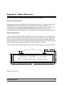
Chapter 1
Setting Up Your Display For Operation
This chapter describes how to set up the display hardware for operation, including setting the dip
switches, connecting power, and wiring to the serial communication port. There are many
references in this chapter to the term host device. Simply stated, the host device is whatever
device will be sending serial data to the M1000 display. Some typical host devices are PLC
BASIC modules, computers, scales, master clock systems, panel meters, etc.
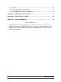
1.1
Accessing Wiring Connections And Selection Switches
All external power and communication line connections to the display are made to printed circuit
board mounted terminal strips. These terminal strips, as well as a COM PORT selection switch
can be accessed by removing the wiring user access plate.
WARNING - SHOCK HAZARD
Always completely disconnect power from the display before
opening the user access plate. Do not reapply power to the
display until the access plate has been reinstalled and
securely closed.
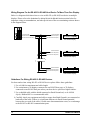
There are three liquid tight fittings on the Wiring access plate, provided for bringing external
wiring into the display enclosure. The left most conduit opening is provided for power wiring,
the center and right most for signal wiring. It is not recommended to run power wiring and
signal wiring in the same conduit!
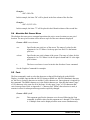
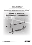
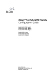
A 8 position DIP switch, two rotary DIP switches, and the EPROM of the unit can be accessed
by removing the rightmost access plate.
Access Plates
C
B
A
8
7
6
5
4
3
2
1
SW1
UP RS-422
DOWN RS-232
M1000 Users Manual
EPROM
1
0
9
2 3
8 7
4
1
5 0
6
9
2 3
8 7
ON
4
5
6
1
2
3
4
5
6
7
8
3
1.2
Setting The DIP Switches For Your Application
Note: Changes to the DIP switches are only acknowledged at power up. Factory default settings
are shown in gray.
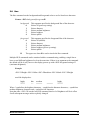
Baud Rate
The baud rate of your M1000 series display determines how fast serial data will be
communicated to the display. In all cases this setting must match the baud rate of the device that
will be sending serial data to the display (the host device).
3
OFF
OFF
OFF
OFF
ON
ON
ON
ON
2
OFF
OFF
ON
ON
OFF
OFF
ON
ON
1
Baud Rate
OFF
300
ON
600
OFF
1,200
ON
2,400
OFF
4,800
ON
9,600
OFF
19.2K
ON NOT USED
Data Bits
The number of Data Bits selected must match the number of data bits transmitted by the host.
4
Data Bits
ON
8
OFF
7
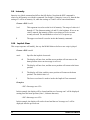
Power Up Font
The Power Up font determines what font the M1000 will use after power up. All data received
after power up will use this font setting until a new font command is selected.
7
OFF
OFF
OFF
OFF
ON
ON
ON
ON
6
OFF
OFF
ON
ON
OFF
OFF
ON
ON
5
OFF
ON
OFF
ON
OFF
ON
OFF
ON
Font #
1
1
2
3
4
5
6
1
Description
2 lines by 20 characters
2 lines by 20 characters
2 lines by 15 characters
1 line by 10 characters
1 line by 8 characters
1 line by 15 characters
1 line by 12 characters
2 lines by 20 characters. Powers up blank.
At power up the M1000 displays a diagnostic screen which shows the firmware version, and an
information screen which shows the Baud rate, Data bit and address setting. Six seconds after
this message appears, the unit will accept serial data.
4
M1000 Users Manual
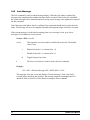
Reserved
Switch 8 is reserved for future features, or custom operation.
8
Reserved
ON
Special
OFF Standard
Unit Address Switches
Unit Address is a rotary DIP switch selection that allows you to select an individual unit
address. Individual unit addresses can range from 01 to 99, allowing up to 99 displays to be
individually addressed in a network. Address 00 selects no address.
Addressing Multiple Displays
Using an RS-422 or RS-485 network (described in Section 1.6 RS-422 Or RS-485 Communication
To One Or More Displays) together with addressing allows a host computer or PLC to
communicate with specific individual displays. Each display in the network may be assigned a
unit address. If you do not need to address individual displays, simply leave the display set to the
default setting of address 00, and skip this section.
If a message is directed to a specific unit address, only units set to that address will respond to
the data. More than one display may use the same unit address. Remember, if the data in the
message is meant for a specific unit address, the address command must follow the <ESC>
character in the transmission packet (as shown in the examples below).
The following examples assume that Unit Address is set to 10.
To Show Only On Displays With A Unit Address Of 10...
Transmit
Hello
<ESC>10AHello<CR>
Test Message
<ESC>10ATest Message<CR>
M1000 Users Manual
5
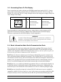
1.3
Connecting Power To The Display
Power connections are made to the three pin POWER terminal strip (marked A B C). Connect
power to this terminal strip as shown below. For M1000-120 refer to the 120VAC wiring. For
M1000-220, refer to the 220VAC wiring. Wiring the unit to the wrong power supply voltage can
cause damage to the display.
3 Pin POWER Terminal Strip (P1)
C
B
Pin
120 VAC Powered Units
220 VAC Powered Units
A
120 VAC (Hot)
220 VAC (Hot)
B
120 VAC (Neutral)
220 VAC (Neutral)
C
Earth Ground
Earth Ground
A
Proper grounding is an important aspect of power wiring, both as a safety measure and for
improved electrical noise immunity. Always connect Earth Ground to the M1000 display.
The power requirement for the M1000 display is listed in Appendix A.
WARNING
Terminal C (Earth Ground) must always be connected to a reliable low
impedance earth ground. This provides a safety ground to the enclosure,
as well as a return path for electrical noise.
1.4
Basic Information About Serial Communication Ports
This section provides some basic background information regarding different types of serial
communication ports. Each M1000 display contains both an RS-232 port and an RS-485 port
(which is also compatible with RS-422 communication), however, only one of the two ports can
be used at any given time to communicate with a host device.
RS-232 ports are the most common type of serial ports, although they are more common in an
office environment than an industrial environment. This is because RS-232 can only be run for
short distances (under 50 feet), and in environments where EMI (electromagnetic interference) is
minimal. Also, one host RS-232 port is normally limited to directly communicating with one
device. Every M1000 display has a built in data converter that overcomes this limitation.
RS-422 ports are very common in industrial environments. They are well suited for distances up
to 4000 feet, and have substantially superior EMI immunity characteristics. Additionally, one
host RS-422 port can communicate with a minimum of 10 devices without repeating the signal.
RS-485 ports are basically an improved version of RS-422, and in most cases are completely
compatible with RS-422 devices (and vice versa). In fact, many newer products with built in RS422 ports actually use driver circuits that meet the RS-485 specification (M1000 displays fall
6
M1000 Users Manual
into this class). RS-485 offers better EMI immunity characteristics, and improved drivers that
have the ability to communicate with up to 32 devices without repeating the signal. There is
sometimes confusion regarding RS-485 because it has an additional ability to communicate in
both directions over one pair of wires, a feature not supported by RS-422 or by the M1000
display.
20 mA current loop was commonly used for industrial applications in the past but is less
common today. To use a 20mA current loop serial port with an M1000 display, all that is
required is an external 20 mA current loop to RS-422 converter. Vorne can provide such a
converter if your application requires it.
1.5
RS-232 Communication To A Single Display
This section provides the information necessary to successfully interface a host RS-232 port to
one M1000 display. If you would like to interface a host RS-232 port to multiple M1000
displays, read this section as well as sections 1.6 and 1.7.
Selecting RS-232 Communication
A printed circuit board mounted COM PORT push / pull switch (labeled SW1), located
approximately one inch to the right of the 8 pin COM PORT terminal strip, is used to select
between RS-232 and RS-422/RS-485 communication. When the switch is pushed down, RS232
is selected. If the switch is pulled up, RS422/RS485 is selected. Set this switch to the RS-232
position.
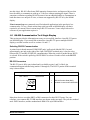
RS-232 Connectors
The RS-232 port is fully opto-isolated and is available on pins 1 and 2 of the 8 pin
communication port terminal strip (marked 1 through 8). The RS-232 portion of this terminal
strip is shown below.
8 Pin COM PORT Terminal Strip (P2)
Pins 1 and 2
Pin
Function
RS-232 Port
2
1
1
RS-232 Receive Data (RxD)
2
Isolated Communication GROUND
Many host devices use either DB25 or DB9 connectors for their RS-232 ports. For your
reference, two common RS-232 DB interfaces are shown on the next page. They are the standard
male DB25 interface, and the standard male IBM/AT® style DB9 interface.
M1000 Users Manual
7
Standart Host Device RS-232 DB Connectors
DB25 MALE
DB9 MALE
Data Carrier Detect (DCD)
Signal Ground
Data Set Ready (DSR)
Clear To Send (CTS)
Request To Send (RTS)
Receive Data (RxD)
Transmit Data (TxD)
Data Carrier Detect (DCD)
Receive Data (RxD)
Transmit Data (TxD)
Data Transmit Ready (DTR)
Signal Ground
1
2
3
4
5
6
7
8
9
10 11 12 13
1
14 15 16 17 18 19 20 21 22 23 24 25
2
6
3
7
4
8
5
9
Data Terminal Ready (DTR)
Ring Indicator (RI)
Clear To Send (CTS)
Request To Send (RTS)
Data Set Ready (DSR)
Ring Indicator (RI)
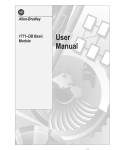
Wiring Diagram For An RS-232 Host Device To One Display
The only connections necessary for one way communication between a host device and an
M1000 display are the ones shown in the diagram below. Please refer to the Guidelines For Wiring
RS-232 Devices section below for important wiring recommendations.
PLC
Transmit Data (TxD)
Signal GROUND
Receive Data (RxD)
1
Isolated GROUND
2
M1000 Display
HOST DEVICE
Guidelines For Wiring RS-232 Devices
For best results when wiring RS-232 devices please follow these guidelines:
1. Use a 50 foot maximum cable length.
2. Use a baud rate of 19,200 or less.
3. Use a shielded cable with the shield connected to Earth Ground only at the M1000
display. Belden 9842 is a recommended cable.
4. Carefully check your equipment and cable to ensure that Earth Ground is not connected at
both ends of the cable. If there is a significant difference in Earth Ground potential
between the two ends of the cable, it could cause data transmission errors, or even damage
to the RS-232 communication ports.
5. Keep the cable length as short as possible, and do not run the RS-232 cable parallel to any
power cables.
8
M1000 Users Manual
1.6
RS-422 Or RS-485 Communication To One Or More Displays
This section provides the information necessary to successfully interface a host RS-422 or RS485 port to one or more M1000 displays. Note that the M1000 display contains an opto-isolated
RS-485 port which is also fully compatible with RS-422 host devices.
Selecting RS-422/RS-485 Communication
A printed circuit board mounted COM PORT push / pull switch (labeled SW1), located
approximately one inch to the right of the 8 pin COM PORT terminal strip, is used to select
between RS-232 and RS-422/RS-485 communication. When the switch is pushed down, RS232
is selected. If the switch is pulled up, RS422/RS485 is selected. Set this switch to the RS-422
position.
RS-422/RS-485 Connectors
The RS-422/RS-485 port is fully opto-isolated and is available through the last five pins of the
eight pin communication port terminal strip (marked 1 through 8). The RS-422/RS-485 portion
of this terminal strip is shown below.
8 Pin COM PORT Terminal Strip (P2)
Pins 4 to 8
Pin
RS-422/RS-485 Port
8
7
6
5
4
Function
4
Isolated Communication GROUND
5
RS-422/RS-485 Receive Data (RxD) +
6
RS-422/RS-485 Receive Data (RxD) -
7
RS-422/RS-485 Retransmit +
8
RS-422/RS-485 Retransmit -
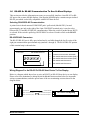
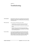
Wiring Diagram For An RS-422 Or RS-485 Host Device To One Display
Below is a diagram which shows how to wire an RS-422 (or RS-485) host device to one display.
Please refer to the Guidelines For Wiring RS-422 Or RS-485 Devices section below for important
wiring recommendations, and take special note of the two terminating resistors shown in the
diagram below.
PLC
Signal GROUND
Isolated GROUND
4
RS-422 Transmit Data (TxD) +
RS-422 Receive Data (RxD) +
5
RS-422 Transmit Data (TxD) -
RS-422 Receive Data (RxD) -
6
M1000 Display
HOST DEVICE
M1000 Users Manual
9
Wiring Diagram For An RS-422 Or RS-485 Host Device To More Than One Display
Below is a diagram which shows how to wire an RS-422 (or RS-485) host device to multiple
displays. Please refer to the Guidelines For Wiring RS-422 Or RS-485 Devices section below for
important wiring recommendations, and take special note of the two terminating resistors shown
in the diagram below.
PLC
Signal GROUND
Isolated GROUND
4
RS-422 Transmit Data (TxD) +
RS-422 Receive Data (RxD) + 5
RS-422 Transmit Data (TxD) -
RS-422 Receive Data (RxD) - 6
M1000 Display
1ST M1000 Display
HOST DEVICE
Isolated GROUND
4
RS-422 Receive Data (RxD) +
5
RS-422 Receive Data (RxD) -
6
M1000 Display
2ND M1000 Display
Isolated GROUND
4
RS-422 Receive Data (RxD) +
5
RS-422 Receive Data (RxD) -
6
M1000 Display
LAST M1000 Display
Guidelines For Wiring RS-422 Or RS-485 Devices
For best results when wiring RS-422 or RS-485 devices please follow these guidelines:
1. Use a 4,000 foot maximum total cable length.
2. Use a maximum of 10 displays connected to one RS-422 host port, or 32 displays
connected to one RS-485 host port unless your host device specifies a higher number.
3. Use a shielded cable with the shield connected to Earth Ground only at the M1000
display. Belden 9843 is a recommended cable.
4. Carefully check your equipment and cable to ensure that Earth Ground is not connected at
both ends of the cable. If there is a significant difference in Earth Ground potential
between the two ends of the cable, it could cause data transmission errors, or even damage
to the RS-422 or RS-485 communication ports.
10
M1000 Users Manual
5. Terminate the cables. In all RS-422 and RS-485 installations, the cable must be correctly
terminated with a set of resistors, one set at each end of the network. This applies even if
you are only using one display connected to one host device. The terminating resistors
prevent reflection problems that can interfere with data transmission. The resistance value
of the terminating resistors should match the characteristic impedance of the cable. A
typical value is 120 ohms. The terminating resistors must be placed at the two farthest
ends of the RS-422 or RS-485 network, regardless of where the host device is. In some
cases host device RS-422 and RS-485 ports have built in or optional terminating resistors.
Take care to check that your network (whether it has one display or 32 displays) has only
one set of terminating resistors.
6. In applications with multiple displays, bring the communication wiring point to point. In
other words do not run stubs from the "backbone" network wiring to each display. If you
find it absolutely necessary to run a stub from the backbone network wiring, make sure it
is under one foot in length.
1.7
RS-232 Communication To More Than One Display
M1000 displays have a built in data converter that can be used to convert host device RS-232
data to RS-485 data and vice versa. This allows the host device to communicate via RS-232 to
one M1000 display (called the converting display), which will retransmit any RS-232 data
received from the host device as RS-485 data to all other displays in the network.
To wire a network of displays that can be communicated to from one host device RS-232 port,
follow these steps:
Step 1: Wire your host device RS-232 port to the first display's RS-232 port as described in
Section 1.5 RS-232 Communication To A Single Display. This display will be the
converting display. Make sure to set the COM PORT push / pull switch to the RS-232
position only for the converting display. All other displays in the network should have
the COM PORT push / pull switch set to the RS-422 position.
Step 2: Use the converting display's RS-485 port to connect to other displays in the network as
described in Section 1.6 RS-422 Or RS-485 Communication To One Or More Displays.
Where Retransmit + of the converting display is connected to RxD+ of the other
displays in the network and Retransmit - of the converting display is connected to RxDof the other displays in the network.
M1000 Users Manual
11
Chapter 2
Message Structure and Escape Commands
The M1000 is a serial input alphanumeric display capable of receiving and displaying RS232,
RS422 or RS485 serial ASCII data with field selectable data formats and baud rates. The full set
of 256 ASCII characters can be displayed with a variety of display fonts, allowing versatile
display formatting. A simple to use command structure provides for scrolling, sparkling and
blinking text, as well as intensity control of the display.
Communication to the M1000 is accomplished by sending a formatted string of ASCII literal
characters and escape commands terminated with a <CR> (carriage return) to the display. The
maximum length of a transmission is 256 characters, including all escape commands, literal
characters and terminating characters.
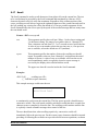
The following example outlines the basic protocol for communication with the display. In this
example literal characters are represented by (t) and the most important position dependent
escape commands are shown. A more complete discussion of the escape commands follows.
<ESC>##A<ESC>#Lttt. ..tttt<CR>
<ESC>##A (address) must be the first group of characters. This allows the M1000 to recognize
the subsequent data. An address can appear only once in a message.
<ESC>#L (line number), if used, must follow the address command. The subsequent text is
displayed on the specified line.
<CR> is the terminating character and causes action to take place on the message just received.
Previous information on the M1000 continues to be displayed while a new message is received
(up to the receipt of <CR>).
#'s are ASCII numbers 0 to 9, -, or +. A field of ### can have a maximum value of 255. Absence
of a # implies 0. A + or - without a number, implies +1 or -1.
Example Message
<ESC>24A<ESC>S Test Message<CR>
The example packet would send the message:
<ESC>S Test Message
to a M1000 display set to address 24. The script instructs the M1000 display to scroll the text "
Test Message" on the first line.
12
M1000 Users Manual
Displaying Literal Text
The most basic message for a M1000 display involves the printing of literal text on the LED
display. The message for this function is formed exactly as it is to be displayed. For example, to
display the phrase "Hello, world!", the message would be composed of the text within the double
quotes. The cursor will be left in the character position immediately following the displayed text.
Message #1:
Hello, world!
If a second message "Bad results." immediately follows the first message, it would over write the
first phrase because the display is cleared before each new message is displayed. This feature can
be changed by using the Implicit Clear command described in section 2.10.
The M1000 display treats incoming text much like a terminal. Characters will be placed one after
the other on the screen until the end of the display line is reached. When the end of the display
line is reached, one of two possible results can occur. If the text was on the top line, additional
characters will be placed on the display starting at the leftmost position of the bottom line. If the
text was on the bottom line, any characters received past the end of the line are not displayed.
Using Control Characters
Control characters can be used to control how messages appear on the display. These control
characters are treated as special functions by the display. They allow a message to clear the
screen and move the cursor around the screen simply by including them as part of the message
text. The Table below gives a list of available control characters. Since control characters are not
displayable on most terminals or computers, a control character in this manual will always be
depicted as a code name abbreviation enclosed between angle brackets. For example, the ASCII
Form Feed character, decimal value 12, will be shown as <FF>. The real message must contain
the actual ASCII code (see Literal Control Characters later in this section).
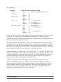
Control Characters
Code Name
Null
End of Transmission
Backspace
Horizontal Tab
Hex Abbr. Function
00h <NUL> Ignored
04h <EOT> Marks the end of a scrolled portion of text.
08h
09h
Line Feed
0Ah
Vertical Tab
Form Feed
0Bh
0Ch
Carriage Return
Escape
0Dh
1Bh
M1000 Users Manual
<BS> Move the cursor back (left) one position.
<HT> Move the cursor to the next tab stop. Stops are set at
character columns 8 and 16.
<LF> Ignored. (allows <CR><LF> combinations as terminators).
<VT> Move the cursor to the leftmost position of the next line.
<FF> Clear the display and move the cursor to the leftmost
position of the top line.
<CR> Terminates a message.
<ESC> Process the next characters as a command.
13
Command Strings
The combination of literal text and the control characters shown above illustrate how a great
variety of text can be displayed on the M1000. Additional features such, as blinking and
different fonts require an additional control character, <ESC>. The <ESC> character, decimal
value 27, is used by the M1000 to mark the beginning of a special display command. All
extended functions are built using escape command sequences.
All escape command strings must begin with the <ESC> character and end with an upper or
lower case letter. The letter is the part of the sequence, which describes its function. Since there
are 26 letters in the alphabet and both upper and lower case letters are used, there are 52 possible
commands available. The M1000 uses far less than 52, making it possible to let the letter have
meaning to the user. For example, the letter 'B' is used to end the Blink command and 'C' refers
to the Cursor command.
Between the <ESC> character and the command letter is the argument list for the command. It is
the argument list, which allows the cursor command to move to a specific location or choose
whether blink should be on or off. An individual argument is a number in the range -1 to +255. A
semicolon is placed between adjacent arguments to separate them. The arguments are arranged
in a reverse ordered list called a stack. As the display reads the escape sequence, it must separate
the arguments.
The display considers an argument to begin when it finds a digit, '0' through '9', or a '+', or a '-'.
The end of the argument is assumed to be the first non-digit found. If the sequence is correctly
formatted, all arguments will end with a semicolon or the actual command letter for the function.
Once the display has found an entire argument, it is placed on the stack, as shown in the Stack
Handling Table on the next page. The arguments wait on the stack until the display finds a
command letter. When the command letter is found, the display begins removing arguments
from the top of the stack to use in the command. The very first argument removed from the stack
will always be the argument immediately preceding the command letter. If an argument list is
shorter than the number required for a command, then attempting to get an argument from the
stack will result in a zero value argument. Please note the shortcut arguments used in The Stack
Handling Table. They are used to conserve message space. Extra spaces preceding an argument
are ignored. This accommodates serial systems, which insert a leading space for any positive
number printed.
14
M1000 Users Manual
Stack Handling
Sequence
<ESC>C
<ESC>2;3C
Stack After Sequence Has Been Read
Top:
0 Note: No argument Defaults to zero
Top:
+3
Bottom:
+2
+5
<ESC>2;-3;5C
Top:
-3
Next:
+2
Bottom:
+1 '+' is a shortcut for +1
<ESC>-;;+C
Top:
0 No argument = 0
Next:
-1 '-' is a shortcut for -1
Bottom:
0 No argument = 0
<ESC>255;-;3;0;+;C Top:
+1 '+' is a shortcut for +1
Next:
0
Next:
+3
Next:
'-' is a shortcut for -1
-1
Next:
Bottom: +255
Each command letter determines the number of arguments required and the valid values that can
be assigned. For example, the Cursor command (command letter C) expects to find two
arguments on the stack. The top of the stack is always considered to be the column position and
the next argument is always the line position.
For the first sequence in the table above, <ESC>C, the column to move to is zero. The Cursor
command expects two arguments to be present in the script. The missing argument will be given
the value of zero. In this case, the result should be to move the cursor to column zero, line zero.
Since zero is not a valid value, the value "zero" will be replaced with the value "one". The actual
result of this script would be to move the cursor to column one, line one.
In the third sequence, the column value is five. The line value "-3" is negative. For negative Line
values, the result will be no line cursor movement. Therefore, the result of this sequence would
be to move the cursor to column five of the current line. The Cursor command only expects two
arguments and the third sequence has more than two arguments. When more arguments are
present than expected, the extra arguments will be discarded.
Virtually every feature of the M1000 display can be accessed with some kind of escape
sequence, allowing messages to have complete control of the M1000 display unit. Escape
sequences fall into two broad categories: Display Attribute Control and Script Flow Control.
Display Attribute controls are used to determine the appearance of the displayed text. Script
Flow controls are used to control the order in which it is processed. The following Table
summarizes the standard M1000 series escape sequences.
M1000 Users Manual
15
Standard M1000 Display Escape Sequences
Command
Letter Type
Marker
@ Flow
Blink
B
Display
Inverse Blink
b
Display
Cursor
C
Display
Absolute cursor move
c
Display
Font
F
Display
Goto
G
Flow
Graphics
g
Display
Hue
H
Display
Intensity
I
Display
Implicit Clear
i
Display
Line
L
Display
Lock Message
l
Flow
Move Pixel Cursor
m Display
Pixel Draw
p
Display
Repeat
R
Display
Scroll
S
Flow/Display
Wait
W Flow
Description
Mark the return place for a Goto command.
Control blinking of characters.
Select inverse blink.
Set the next display write position.
Reposition cursor to pixel location.
Choose a character set.
Loop back to a script marker.
Select graphics mode.
Set character foreground & background color.
Set brightness level.
Select new message handling.
Select line to use.
Lock message until completed.
Move pixel cursor specified distance.
Select color of pixel location.
Repeat character a specified number of times.
Set scrolling for the current line.
Stop message execution for a while.
Simple Examples To Try
This example assumes that the unit address is set to 0. Refer to the following sections for more
information on the Scroll (2.17), Cursor (2.3), and Blink (2.1) commands used below.
Let's display message "Status OK!" on line 1 of the display.
Status OK!<CR>
Now, let's scroll the message "Status OK! " on line 2 of the display.
<ESC>2;1C<ESC>28;SStatus OK! <CR>
Notice that the fixed text on line 1 was not cleared.
Now, let's blink the text "WARNING! " on line 1 of display starting at column 8.
<ESC>1;8C<ESC>128;+BWARNING!<ESC>-B<CR>
Once the blink message is received, the scrolling message will stop scrolling and the blinking
message will appear in the location specified without clearing the first line.
We're done!
16
M1000 Users Manual
Literal Control Characters
Control
Character
<NUL>
<SOH>
<STX>
<ETX>
<EOT>
<ENQ>
<ACK>
<BEL>
<BS>
<HT>
<LF>
<VT>
<FF>
<CR>
<SO>
<SI>
<DLE>
<DC1>
<DC2>
<DC3>
<DC4>
<NAK>
<SYN>
<ETB>
<CAN>
<EM>
<SUB>
<ESC>
<FS>
<GS>
<RS>
<US>
<DEL>
M1000 Users Manual
HEX/ASCIl Decimal Value
Value
0
0
1
1
2
2
3
3
4
4
5
5
6
6
7
7
8
8
9
9
0A
10
0B
11
0C
12
0D
13
0E
14
0F
15
10
16
11
17
12
18
13
19
14
20
15
21
16
22
17
23
18
24
19
25
1A
26
1B
27
1C
28
1D
29
1E
30
1F
31
7F
127
Character
NA
A
B
C
NA
E
F
G
NA
NA
NA
NA
NA
NA
N
O
P
Q
R
S
T
U
V
W
X
Y
Z
NA
\
]
^
_
`
17
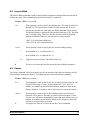
2.1
Blink
The Blink command is used to make displayed characters blink at a specified rate. The text to be
blinked must be bracketed on each side by a Blink command string.
Format: <ESC>rate;switchB
rate
This argument is used to specify the blinking rate. The range of values is 1
through 255. The fastest rate is 1 and 255 is the slowest rate. If zero is
entered, the rate that was used in the last Blink command will be chosen.
The M1000 Display is initialized with a default blink rate of 20. The blink
rate is a global setting. Therefore, display characters with the blinking
attribute will blink at whatever rate was most recently selected.
<ESC>128;+B is a midrange blink rate
<ESC>1;+B is the fastest blink rate
<ESC>255;+B is the slowest blink rate
switch
This argument is used to turn blinking on, off, or to toggle the current
setting. Toggle is useful for terminating Blink in a script.
+
Blink on (+ is a shortcut for +1).
-
Blink off (- is a shortcut for -1).
0
Toggle from previous state. If the first Blink command starts text blinking,
the second Blink command can have zero entered for this argument which
would toggle the Blink command from start blinking to stop blinking. The
default value is 0.
B
The upper-case letter B is used to invoke the Blink command.
Example:
<ESC>+B Blinking<ESC>B Not<CR>
In this example, two Blink command strings are included. The first command string turns
on the blink effect and the second command string terminates the blink effect. The word
"Blinking" will blink at the previously selected or default blink rate. The word "Not" will
not blink.
18
M1000 Users Manual
2.2
Inverse Blink
The Inverse Blink command is used to make displayed characters alternate between text and an
all dots on screen. This command will remain active until it is turned off.
Format: <ESC>rate;switchb
rate
This argument is used to specify the blinking rate. The range of values is 1
through 255. The fastest rate is 1 and 255 is the slowest rate. If zero is
entered, the rate that was used in the last Blink command will be chosen.
The M1000 Display is initialized with a default blink rate of 20. The blink
rate is a global setting. Therefore, display characters with the blinking
attribute will blink at whatever rate was most recently selected.
<ESC>1;+B is the fastest blink rate
<ESC>255;+B is the slowest blink rate
switch
This argument is used to specify the new inverse blinking setting.
+
Inverse Blink on (+ is a shortcut for +1).
-
Inverse Blink off (- is a shortcut for -1).
0
Toggle from previous state. The default value is 0.
b
2.3
The lower-case letter b is used to invoke the Inverse Blink command.
Cursor
The Cursor command is used to explicitly specify the position where the next character will be
placed without clearing the display. Two arguments are associated with this command.
Format: <ESC>line;columnC
line
This argument is used to specify the line on which the next character will
be placed. The range of values for this argument is 1 or 2. Zero, no
number, or a number greater than the maximum number of lines on the
display, default to 1. Negative values will result in no cursor movement.
column
This argument is used to specify the column position where the next
character will be placed. The range of values for this argument is 1 thru
20. One is the left most column and 20 is the right most column. Zero, no
number, or numbers greater than 20 default to one. Negative values will
result in no column cursor movement.
The upper-case letter C is used to invoke the Cursor command.
C
M1000 Users Manual
19
Example:
<ESC>CM<CR>
In this example, the letter "M" will be placed in the first column of the first line.
Example:
<ESC>2;15CT<CR>
In this example, the letter "T" will be placed in the fifteenth column of the second line.
2.4
Absolute Dot Cursor Move
The absolute dot cursor move command repositions the active cursor location to a new pixel
location. The new pixel location will be the new top left of the next character displayed.
Format: <ESC>row;columnc
row
Specifies the new pixel row of the cursor. The range of values for this
argument is 0 to 15. Where 0 is the top pixel row and 15 is the bottom
pixel row.
column
Specifies the new pixel column of the cursor. The range of values for this
argument is 0 to 119. Where 0 is the left pixel column and 119 is the right
pixel column.
c
The lower-case letter c is used to invoke the Absolute Cursor command.
See the Graphics Command for examples.
2.5
Font
The Font command is used to select the character set that will be displayed on the M1000
Display. Available fonts include the full 256 character IBM® set, the JIS8 (Katakana) character
set, the Slavic (Latin II) character set and the Cyrillic character set. One argument is required for
this command. The IBM® character set is the default character set. Note that the bottom "page"
of 128 characters is the same for all of the fonts. It is the upper "page" of 128 characters that
varies between fonts. Refer to Appendix C - Character Sets. When a font selection is made, it
remains in effect for subsequent messages unless explicitly changed.
Format: <ESC>fontF
font
20
This argument specifies the character set to be used following the Font
command. Available values for this argument are 1 through 9. The default
is 1. Multiple fonts can be displayed on the same screen simultaneously.
M1000 Users Manual
1
2
3
4
5
6
7
8
9
F
8x6 pixels
8x8 pixels
16x12 pixels
16x15 pixels
16x8 pixels
16x10 pixels
8x6 pixels
8x6 pixels
8x6 pixels
2 lines of 20 characters.
2 lines of 15 characters.
1 lines of 10 characters.
1 lines of 8 characters.
1 lines of 15 characters.
1 lines of 12 characters.
2 lines of 20 characters.
2 lines of 20 characters.
2 lines of 20 characters.
Selects the full IBM® set.
Selects the full IBM® set.
Selects the full IBM® set.
Selects the full IBM® set.
Selects the full IBM® set.
Selects the full IBM® set.
Selects JIS8 (Katakana) set.
Selects the Slavic set.
Selects the Cyrillic set.
The upper-case Letter F is used to invoke the Font command.
Example:
<ESC>3F<CR>
In this example, the one line by ten character set will be used for the text following the
Font command entry.
2.6
Goto
The Goto command is used to repeat the preceding text and commands the number of times
specified by the argument. The repeated portion of the message would be from the Marker
position. Refer to the description of the Marker command, Section 2.13. One argument is
required for this command.
Note: If a marker command is not included in a message containing a Goto command,
the Goto command will loop to the beginning of the message.
Format: <ESC>repeatG
repeat
This argument specifies the number of times to repeat the preceding part
of the message before the display will move on to process the rest of the
message. The range of values for this argument is 0 through 255. Zero will
cause repeating until a new message (also called an infinite goto). The
default value is zero.
G
The upper-case letter G is used to invoke the Goto command.
Example:
Repeat again<ESC>@<HT> and again<ESC>2G!!<CR>
This script executed on a M1000 will clear the display, write "Repeat again" on the first
line and then repeat two times the process of moving to the next tab stop and writing "and
again". Finally, the unit will write "!!" following the last repeated text. Note that the
M1000 Users Manual
21
Marker for the Goto in the example message is <ESC>@. The resulting message would
appear as:
Repeat again
and
again
and again!!
2.7
Graphics
The graphic mode command allows individual pixels to be written. When in graphics mode,
characters that would ordinarily be displayed are instead interpreted to be the new color of the
pixel at the active cursor location. Once written, the active position is moved one pixel to the
right. Writing past the end of the line will cause unpredictable results.
7 6 5 4 3 2 1 0 Definition
X X 00 = off, 01 = low, 10 = medium, 11 = high
X
0 = no sparkle, 1 = sparkle
X
0 = no flash, 1 = flash
Format: <ESC>switchg
switch
Specifies the new mode of the display.
+
Graphic Mode on (+ is a shortcut for +1).
-
Graphic Mode off (- is a shortcut for -1).
0
Toggle from previous state. The default value is 0.
g
The lower-case letter g is used to invoke the Graphic command.
Example:
By using the Absolute Dot Cursor Move and Move Pixel Cursor commands, the goto command,
and the graphics mode command, interesting pseudo-special effects can be created. For example,
to create a marquee, send the following data stream to the M1000 display (the line is split up for
legibility; the entire sequence can be sent as one data stream):
<ESC>+g<ESC>c4<ESC>@4567<ESC>29G455<ESC>1;c4<ESC>@4567<ESC>29G455
<ESC>2;c77<ESC>116m66<ESC>3;c66<ESC>116m77<ESC>4;c55<ESC>116m44
<ESC>5;c44<ESC>116m55<ESC>6;c77<ESC>116m66<ESC>7;c66<ESC>116m77
<ESC>8;c55<ESC>116m44<ESC>9;c44<ESC>116m55<ESC>10;c77<ESC>116m66
<ESC>11;c66<ESC>116m77 <ESC>12;c55<ESC>116m44<ESC>13;c44<ESC>116m55
<ESC>14;c7<ESC>@7654<ESC>29G766<ESC>15;c7<ESC>@7654<ESC>29G766<ESC>-g
22
M1000 Users Manual
2.8
Hue
The Hue command sets the background and foreground color to use for literal text characters.
Format: <ESC>background;foregroundH
background
0
1
2
3
4
This argument specifies the background Hue of the character.
Selects off (power up setting).
Selects dimmest.
Selects medium brightness.
Selects brightest.
Selects sparkle.
foreground
0
1
2
3
4
This argument specifies the foreground Hue of the character.
Selects off (default).
Selects dimmest.
Selects medium brightness.
Selects brightest (power up setting).
Selects sparkle.
H
The upper-case letter H is used to invoke the Hue command.
Multiple HUE commands can be contained within a command string, enabling a single line to
have several different brightness levels at the same time. If there is no argument to the command
the default will be 0 (off), however the display powers up with a HUE foreground setting of 3
(maximum brightness).
Example:
<ESC>3Hbright <ESC>1Hdim <ESC>2Hmedium <ESC>Hdark <ESC>3Hbright
would be displayed as:
bright
*****
dim
----
medium
++++++
======
bright
******
Where * symbolizes the brightest characters, - symbolizes the dimmest characters, + symbolizes
medium brightness characters and = symbolizes off characters.
Note that since <ESC>3H was the last HUE command, that level of brightness will be in effect
for all subsequent messages unless explicitly changed.
M1000 Users Manual
23
2.9
Intensity
Intensity is a global command and affects the full display. Note that the HUE command is
relative to the intensity set with this command. For example, if intensity is set to 10, then the hue
setting of 3 will be at intensity 10, while hue settings of 1 and 2 will be somewhat dimmer.
Format: <ESC>levelI
level
This argument is used to set the level of intensity. The range of values is 0
through 15. The dimmest setting is 0 and 15 is the brightest. If zero or no
value is entered, the intensity will be set at whatever level was most
recently selected. The unit defaults to a level of 15 at power up.
I
The upper-case letter I is used to invoke the Intensity command.
2.10
Implicit Clear
This escape sequence will modify, the way the M1000 behaves before a new script is played.
Format: <ESC>modei
mode
Specifies the implicit clear mode.
0
The display will not clear, and the cursor position will not return to the
home position when a new message is received.
1
The display will not clear, and the cursor position will return to the home
position.
2
The display will clear, and the cursor position will return to the home
position. The default value is 2.
i
The lower-case letter i is used to invoke the Implicit Clear command.
Examples:
<ESC>2imessage one<CR>
In this example, the display will be cleared and the text "message one" will be displayed
starting from the home position (Line 1, leftmost character).
<ESC>0imessage two<CR>
In this example, the display will not be cleared and the text "message two" will be
displayed after the previous text.
24
M1000 Users Manual
2.11
Line
The Line command is used to specify the line number that text should be written to. The line
command must follow the address and precede the message portion of any data sent to the
M1000. Line commands cannot appear more than once or in any other part of a message. Note
that to use any of the full screen fonts (fonts 3,4 and 5) the display must be selected for line 0
(the entire display).
Format: <ESC>lineL
line
This argument is used to specify the line number to use. The default value
is zero.
0
Selects the entire display.
1
Specifies the top line.
2
Specifies the bottom line.
L
The upper-case letter L is used to invoke the Line command.
<ESC>L defaults to the entire display. Absence of an <ESC>L command implies that a
message is for the same line as the last line number command.
M1000 Users Manual
25
2.12
Lock Message
The lock command is used to control message display. When the lock mode is enabled, the
message must complete before another message can be executed. If the lock mode is disabled,
the current message will be terminated upon receiving a new message. One argument is required
for this command.
Note: Messages with infinite Scroll, or infinite Goto commands should not be used in the lock
mode. The message will never be completed and the subsequent messages will not be executed.
If the current message is locked and executing when a new message is sent, up to 8 new
messages of 256 characters can be queued.
Format: <ESC>switchl
switch
This argument is used to enable or disable the lock mode. The default
value is zero.
+
Enable lock mode (+ is a shortcut for +1).
-
Disable lock mode (- is a shortcut for -1).
0
Toggle from previous state.
l
The lower-case letter l is used to invoke the lock command.
Example:
<FF><ESC>+lPriority Message<ESC>200W<ESC>-l<CR>
This message clears the screen and displays "Priority Message", then waits for 20
seconds before unlocking the message. The message cannot be interrupted until it is
unlocked. Refer to Section 2.18 for details on using the Wait command.
26
M1000 Users Manual
2.13
Marker
The Marker command is used to specify the beginning point of a Goto loop.
Format: <ESC>@
@
This is the matching argument to the marker value in the Goto command
so that the loop is from the Marker location to the Goto command
location. The ASCII symbol @ (40h) is used to invoke the Marker
command.
Example:
I feel <ESC>@GREAT! <ESC>2G<CR>
This example would display as:
I feel GREAT! GREAT!
2.14
Move Pixel Cursor
The Move Pixel Cursor command moves the active cursor the specified distance from the current
location.
Format: <ESC>row;columnm
row
Specifies the distance to move vertically.
-15 to -1
Move up the specified number of pixels.
0
No movement of the pixel cursor.
1 to 15
Move down the specified number of pixels.
column
Specifies the distance to move horizontally.
-119 to -1
Move left the specified number of pixels.
0
No movement of the pixel cursor.
1 to 119
Move right the specified number of pixels.
m
M1000 Users Manual
The lower-case letter m is used to invoke the move pixel cursor command.
27
2.15
Pixel Draw
The pixel draw command changes the color of the specified pixel to the current foreground
color. The active cursor is not affected.
Format: <ESC>row;columnp
2.16
row
Specifies the pixel row location to modify. The range of values for this
argument is 0 to 15. Where 0 is the top row and 15 is the bottom row.
column
Specifies the pixel column location to modify. The range of values for this
argument is 0 to 119. Where 0 is the left column and 119 is the right
column.
p
The lower-case letter p is used to invoke the pixel draw command.
Repeat
The Repeat command allows the character following the command string to be repeated a
specified number of times. This can be used to insert multiple blank characters when scrolling or
reduce the size of messages with many repeating characters. One argument is required for this
command.
Format: <ESC>countR
count
This argument specifies the number of times the character following the
command string is to be repeated. The range of values is 1 to 255. Zero
and one produce one character. The default value is zero.
R
The upper-case letter R is used to invoke the Repeat command.
Example:
<ESC>8R-Vorne<ESC>7R-<CR>
In this example, eight dashes would be displayed, then the word "Vorne" followed by
seven more dashes.
28
M1000 Users Manual
2.17
Scroll
The Scroll command is used to scroll characters, from right to left, on the current line. The text
to be scrolled must be preceded by the Scroll command and terminated by either an <EOT>
character (decimal value 04) or the line terminator. Regardless of the column position of the
cursor, scrolling text will always begin at the rightmost character of the current line and scroll to
the left, pushing any existing text off the line ahead of it. The two possible arguments for the
Scroll command allow the user to specify the speed of the scrolled message and how many times
the text should scroll.
Format: <ESC>rate;repeatS
rate
This argument specifies the scroll rate. Where 1 is the slowest setting and
3 is the fastest setting. The range of acceptable values is 1 through 255.
Thus a character can take from 1.5, 3 or 5 seconds to travel across the line.
A value of zero or no number selects the previous rate, or, if no previous
rate is available, selects the default rate of 2 (medium).
repeat
This argument specifies the number of times the scrolling text should
repeat. Acceptable values are from 1 through 3, and represent the actual
number of repeats. A value of zero or no number will cause the text to
scroll continuously until it is explicitly cleared or a new message is
received by the display (also called an infinite scroll).
S
The upper-case letter S is used to invoke the Scroll command.
Examples:
<ESC>2;0S_ _ _ _ scrolling text<CR>
('_' indicates a space character)
This example message would cause the text
Scrolling text
to continuously scroll across the current line. The four spaces provide a break between
consecutive scrolls. The scroll speed would be such that it would take three seconds for a
character to move completely across the line. The scrolling would continue until the line
is explicitly cleared or another message takes control of the line.
The user should note that, when scrolling repetitively, consecutive scrolls will
immediately follow the previous one. For this reason, space characters should be inserted
preceding or following the scrolled text to provide a break between repetitions, as shown
M1000 Users Manual
29
in the preceding example, it should also be noted that the scrolling will come to a halt on
the last repetition once the last character of the scrolled text (including any spaces) has
appeared at the far right of the line. If it is desired to have the visible text scroll all the
way off the line on the last repetition, the user should either pad the text with 20 trailing
spaces, or use another Scroll command that simply scrolls 20 spaces onto the line. The
first method will insert 20 spaces between each consecutive scroll. The second technique
will allow the user to use fewer spaces between the repeated text and still scroll off the
last repetition.
Example:
<ESC>2;1C<ESC>7S_ _ _ _ _example two<EOT><ESC>1S<ESC>20R_<CR>
('_' indicates a space character)
This example script would cursor to line 2 and scroll the text
example two
seven times at the previously specified or default rate. After the text has scrolled on to the
line for the seventh time, the unit is finished processing the first Scroll command. If the
script ended here, the display would end up showing:
two
example two
However, there is another Scroll command, which will scroll on twenty space characters.
This will have the effect of scrolling off the existing text left over from the first Scroll
command. The second Scroll command specifies the same rate as the first Scroll
command and since there is no delay, the leftover text from the first scroll will simply
keep moving to the left as it is scrolled off by the twenty spaces. Note the use of the
Repeat command as a shortcut to typing twenty space characters.
30
M1000 Users Manual
2.18
Wait
The Wait command is used to pause the processing of a script for a specified length of time. The
Wait command allows timing control and with the Goto command, allows control over
alternating several lines of text or repeating some text or function, without having to retransmit
any data.
Format: <ESC>timeW
time
This is the multiplier used to define the wait period specified with the
function argument. For example, if the delay is to be 10 seconds, the time
value must be 100. Valid values for the time parameter are 0 thru 255. A
value of zero will generate an infinite delay.
W
The upper-case letter W is used to invoke the Wait command.
Example:
<FF><ESC>@WARNING<ESC>20W<FF><ESC>5W
Low Pressure<ESC>30W<FF><ESC>5W<ESC>0G<CR>
This message uses the Wait command in combination with the Goto and Marker
commands to control the timing of a repetitive looping message. The message clears the
display of any existing text, drops a Marker reference, and then writes the text
"WARNING" on the first line. Next, the unit waits for 2 seconds, clears the display, waits
0.5 seconds, and then writes the text "Low Pressure." Following a 3 second wait, the unit
again clears the display, waits 0.5 seconds, and then loops back to the Marker location.
The Goto command specifies continued repetitions, so the script will continue alternating
between "WARNING" and "Low Pressure" until it is terminated by a different message.
M1000 Users Manual
31
2.19
Defeating Hardware Handshaking
The M1000 does not provide Hardware Handshaking. For Host devices, which require Hardware
handshaking, the handshaking lines can be defeated by making the following connections at the
Host devices serial connector.
RTS to CTS
DTR to DCD to DSR
2.20
DB-9 pin #
7 to 8
1 to 4 to 6
DB-25 pin #
4 to 5
6 to 8 to 20
Using XON / XOFF Software Handshaking
In cases where the Host device must wait until a specific message finishes playing, software
handshaking may be used. For software handshaking, pin 3 of the 8 pin Terminal strip must be
connected to the serial input connector of the Host device COM port and the host device must be
set to XON / XOFF handshaking.
If the M1000 is busy, the unit will transmit the ASCII 13h character (DC3) to the Host device.
This will suspend serial transmission by the Host device. When the M1000 is available, the unit
will transmit the ASCII 11h character (DC1) to the Host Device to indicate that serial
transmission can resume.
32
M1000 Users Manual
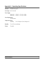
Appendix A
LED Life
Operating Specifications
100,000 hours typical
Serial Input RS-232, RS-485
Power Supply
M1000-120
M1000-220
120VAC +/- 15% (50 - 60 Hz)
220VAC +/- 15% (50 - 60 Hz)
Power Requirements
65W Maximum
Temperature Range
Operating
32 to 122 degrees F (0 to 50 degrees C)
Humidity
5% to 95% non-condensing
Weight
25 pounds
M1000 Users Manual
33
Appendix B
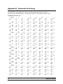
Character Set Listing
The full IBM®, J1S8 (Katakana), Slavic (Latin II) and Cyrillic character sets are
available on the M1000 Display. All fonts share the first 128 characters (00h to 7Fh).
Common Character Set
0
00h
16
10h
P
32
20h
48
30h
0
64
40h
@
80
50h
P
96
60h
`
112
70h
p
1
01h
A
17
11h
Q
33
21h
!
49
31h
1
65
41h
A
81
51h
Q
97
61h
a
113
71h
q
2
02h
B
18
12h
R
34
22h
"
50
32h
2
66
42h
B
82
52h
R
98
62h
b
114
72h
r
3
03h
C
19
13h
S
35
23h
#
51
33h
3
67
43h
C
83
53h
S
99
63h
c
115
73h
s
20
14h
T
36
24h
$
52
34h
4
68
44h
D
84
54h
T
100
64h
d
116
74h
t
4
04h
NA
5
05h
E
21
15h
U
37
25h
%
53
35h
5
69
45h
E
85
55h
U
101
65h
e
117
75h
u
6
06h
F
22
16h
V
38
26h
&
54
36h
6
70
46h
F
86
56h
V
102
66h
f
118
76h
v
7
07h
G
23
17h
W
39
27h
'
55
37h
7
71
47h
G
87
57h
W
103
67h
g
119
77h
w
24
18h
X
40
28h
(
56
38h
8
72
48h
H
88
58h
X
104
68h
h
120
78h
x
25
19h
Y
41
29h
)
57
39h
9
73
49h
I
89
59h
Y
105
69h
i
121
79h
y
26
1Ah
Z
42
2Ah
*
58
3Ah
:
74
4Ah
J
90
5Ah
Z
106
6Ah
j
122
7Ah
z
43
2Bh
+
59
3Bh
;
75
4Bh
K
91
5Bh
[
107
6Bh
k
123
7Bh
{
8
08h
9
09h
10
0Ah
11
0Bh
12
0Ch
13
0Dh
34
NA
NA
NA
NA
NA
NA
NA
27
1Bh
NA
28
1Ch
\
44
2Ch
,
60
3Ch
<
76
4Ch
L
92
5Ch
\
108
6Ch
l
124
7Ch
|
29
1Dh
]
45
2Dh
-
61
3Dh
=
77
4Dh
M
93
5Dh
]
109
6Dh
m
125
7Dh
}
14
0Eh
N
30
1Eh
^
46
2Eh
.
62
3Eh
>
78
4Eh
N
94
5Eh
^
110
6Eh
n
126
7Eh
~
15
0Fh
O
31
1Fh
_
47
2Fh
/
63
3Fh
?
79
4Fh
O
95
5Fh
_
111
6Fh
o
127
7Fh
`
M1000 Users Manual
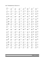
Font 1 through 6 IBM® Character Set
128
80h
a
144
90h
f
160
A0h
q
176
B0h
°
192
C0h
À
208
D0h
Ð
224
E0h
à
240
F0h
ð
129
81h
b
145
91h
‘
161
A1h
¡
177
B1h
±
193
C1h
Á
209
D1h
Ñ
225
E1h
á
241
F1h
ñ
130
82h
‚
146
92h
’
162
A2h
¢
178
B2h
²
194
C2h
Â
210
D2h
Ò
226
E2h
â
242
F2h
ò
131
83h
ƒ
147
93h
“
163
A3h
£
179
B3h
³
195
C3h
Ã
211
D3h
Ó
227
E3h
ã
243
F3h
ó
132
84h
„
148
94h
”
164
A4h
¤
180
B4h
´
196
C4h
Ä
212
D4h
Ô
228
E4h
ä
244
F4h
ô
133
85h
…
149
95h
•
165
A5h
¥
181
B5h
µ
197
C5h
Å
213
D5h
Õ
229
E5h
å
245
F5h
õ
134
86h
†
150
96h
–
166
A6h
¦
182
B6h
¶
198
C6h
Æ
214
D6h
Ö
230
E6h
æ
246
F6h
ö
135
87h
‡
151
97h
—
167
A7h
§
183
B7h
·
199
C7h
Ç
215
D7h
×
231
E7h
ç
247
F7h
÷
136
88h
ˆ
152
98h
˜
168
A8h
¨
184
B8h
¸
200
C8h
È
216
D8h
Ø
232
E8h
è
248
F8h
ø
137
89h
‰
153
99h
™
169
A9h
©
185
B9h
¹
201
C9h
É
217
D9h
Ù
233
E9h
é
249
F9h
ù
138
8Ah
Š
154
9Ah
š
170
AAh
ª
186
BAh
º
202
CAh
Ê
218
DAh
Ú
234
EAh
ê
250
FAh
ú
139
8Bh
‹
155
9Bh
›
171
ABh
«
187
BBh
»
203
CBh
Ë
219
DBh
Û
235
EBh
ë
251
FBh
û
140
8Ch
Œ
156
9Ch
œ
172
ACh
¬
188
BCh
¼
204
CCh
Ì
220
DCh
Ü
236
ECh
ì
252
FCh
ü
141
8Dh
c
157
9Dh
g
173
ADh
−
189
BDh
½
205
CDh
Í
221
DDh
Ý
237
EDh
í
253
FDh
ý
142
8Eh
d
158
9Eh
h
174
AEh
®
190
BEh
¾
206
CEh
Î
222
DEh
Þ
238
EEh
î
254
FEh
þ
143
8Fh
e
159
9Fh
Ÿ
175
AFh
¯
191
BFh
¿
207
CFh
Ï
223
DFh
ß
239
EFh
ï
255
FFh
ÿ
M1000 Users Manual
35
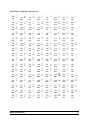
Font 7 JIS8 (Katakana) Character Set
36
128
80h
j
144
90h
n
160
A0h
176
B0h
°
192
C0h
À
208
D0h
Ð
224
E0h
à
240
F0h
ð
129
81h
k
145
91h
‘
161
A1h
¡
177
B1h
±
193
C1h
Á
209
D1h
Ñ
225
E1h
á
241
F1h
ñ
130
82h
‚
146
92h
’
162
A2h
¢
178
B2h
²
194
C2h
Â
210
D2h
Ò
226
E2h
â
242
F2h
ò
131
83h
ƒ
147
93h
“
163
A3h
£
179
B3h
³
195
C3h
Ã
211
D3h
Ó
227
E3h
ã
243
F3h
ó
132
84h
„
148
94h
”
164
A4h
¤
180
B4h
´
196
C4h
Ä
212
D4h
Ô
228
E4h
ä
244
F4h
ô
133
85h
…
149
95h
•
165
A5h
¥
181
B5h
µ
197
C5h
Å
213
D5h
Õ
229
E5h
å
245
F5h
õ
134
86h
†
150
96h
–
166
A6h
¦
182
B6h
¶
198
C6h
Æ
214
D6h
Ö
230
E6h
æ
246
F6h
ö
135
87h
‡
151
97h
—
167
A7h
§
183
B7h
·
199
C7h
Ç
215
D7h
×
231
E7h
ç
247
F7h
÷
136
88h
ˆ
152
98h
˜
168
A8h
¨
184
B8h
¸
200
C8h
È
216
D8h
Ø
232
E8h
è
248
F8h
ø
137
89h
‰
153
99h
™
169
A9h
©
185
B9h
¹
201
C9h
É
217
D9h
Ù
233
E9h
é
249
F9h
ù
138
8Ah
Š
154
9Ah
š
170
AAh
ª
186
BAh
º
202
CAh
Ê
218
DAh
Ú
234
EAh
ê
250
FAh
ú
139
8Bh
‹
155
9Bh
›
171
ABh
«
187
BBh
»
203
CBh
Ë
219
DBh
Û
235
EBh
ë
251
FBh
û
140
8Ch
Œ
156
9Ch
œ
172
ACh
¬
188
BCh
¼
204
CCh
Ì
220
DCh
Ü
236
ECh
ì
252
FCh
ü
141
8Dh
l
157
9Dh
o
173
ADh
−
189
BDh
½
205
CDh
Í
221
DDh
Ý
237
EDh
í
253
FDh
ý
142
8Eh
l
158
9Eh
p
174
AEh
®
190
BEh
¾
206
CEh
Î
222
DEh
Þ
238
EEh
î
254
FEh
þ
143
8Fh
m
159
9Fh
Ÿ
175
AFh
¯
191
BFh
¿
207
CFh
Ï
223
DFh
ß
239
EFh
ï
255
FFh
ÿ
M1000 Users Manual
Font 8 Slavic (Latin II) Character Set
128
80h
a
144
90h
v
160
A0h
q
176
B0h
°
192
C0h
À
208
D0h
Ð
224
E0h
à
240
F0h
ð
129
81h
b
145
91h
‘
161
A1h
¡
177
B1h
±
193
C1h
Á
209
D1h
Ñ
225
E1h
á
241
F1h
ñ
130
82h
‚
146
92h
’
162
A2h
¢
178
B2h
²
194
C2h
Â
210
D2h
Ò
226
E2h
â
242
F2h
ò
131
83h
ƒ
147
93h
“
163
A3h
£
179
B3h
³
195
C3h
Ã
211
D3h
Ó
227
E3h
ã
243
F3h
ó
132
84h
„
148
94h
”
164
A4h
¤
180
B4h
´
196
C4h
Ä
212
D4h
Ô
228
E4h
ä
244
F4h
ô
133
85h
…
149
95h
•
165
A5h
¥
181
B5h
µ
197
C5h
Å
213
D5h
Õ
229
E5h
å
245
F5h
õ
134
86h
†
150
96h
–
166
A6h
¦
182
B6h
¶
198
C6h
Æ
214
D6h
Ö
230
E6h
æ
246
F6h
ö
135
87h
‡
151
97h
—
167
A7h
§
183
B7h
·
199
C7h
Ç
215
D7h
×
231
E7h
ç
247
F7h
÷
136
88h
ˆ
152
98h
˜
168
A8h
¨
184
B8h
¸
200
C8h
È
216
D8h
Ø
232
E8h
è
248
F8h
ø
137
89h
‰
153
99h
™
169
A9h
©
185
B9h
¹
201
C9h
É
217
D9h
Ù
233
E9h
é
249
F9h
ù
138
8Ah
Š
154
9Ah
š
170
AAh
186
BAh
º
202
CAh
Ê
218
DAh
Ú
234
EAh
ê
250
FAh
ú
139
8Bh
‹
155
9Bh
›
171
ABh
«
187
BBh
»
203
CBh
Ë
219
DBh
Û
235
EBh
ë
251
FBh
û
140
8Ch
Œ
156
9Ch
œ
172
ACh
¬
188
BCh
¼
204
CCh
Ì
220
DCh
Ü
236
ECh
ì
252
FCh
ü
141
8Dh
s
157
9Dh
w
173
ADh
−
189
BDh
½
205
CDh
Í
221
DDh
Ý
237
EDh
í
253
FDh
ý
142
8Eh
t
158
9Eh
x
174
AEh
®
190
BEh
¾
206
CEh
Î
222
DEh
Þ
238
EEh
î
254
FEh
þ
143
8Fh
u
159
9Fh
Ÿ
175
AFh
¯
191
BFh
¿
207
CFh
Ï
223
DFh
ß
239
EFh
ï
255
FFh
M1000 Users Manual
37
Font 9 Cyrillic Character Set
38
128
80h
144
90h
160
A0h
176
B0h
192
C0h
208
D0h
224
E0h
240
F0h
129
81h
145
91h
161
A1h
177
B1h
193
C1h
209
D1h
225
E1h
241
F1h
130
82h
146
92h
162
A2h
178
B2h
194
C2h
210
D2h
226
E2h
242
F2h
131
83h
147
93h
163
A3h
179
B3h
195
C3h
211
D3h
227
E3h
243
F3h
132
84h
148
94h
164
A4h
180
B4h
196
C4h
212
D4h
228
E4h
244
F4h
133
85h
149
95h
165
A5h
181
B5h
197
C5h
213
D5h
229
E5h
245
F5h
134
86h
150
96h
166
A6h
182
B6h
198
C6h
214
D6h
230
E6h
246
F6h
135
87h
151
97h
167
A7h
183
B7h
199
C7h
215
D7h
231
E7h
247
F7h
136
88h
152
98h
168
A8h
184
B8h
200
C8h
216
D8h
232
E8h
248
F8h
137
89h
153
99h
169
A9h
185
B9h
201
C9h
217
D9h
233
E9h
249
F9h
138
8Ah
154
9Ah
170
AAh
186
BAh
202
CAh
218
DAh
234
EAh
250
FAh
139
8Bh
155
9Bh
171
ABh
187
BBh
203
CBh
219
DBh
235
EBh
251
FBh
140
8Ch
156
9Ch
172
ACh
188
BCh
204
CCh
220
DCh
236
ECh
252
FCh
141
8Dh
157
9Dh
173
ADh
189
BDh
205
CDh
221
DDh
237
EDh
253
FDh
142
8Eh
158
9Eh
174
AEh
190
BEh
206
CEh
222
DEh
238
EEh
254
FEh
143
8Fh
159
9Fh
175
AFh
191
BFh
207
CFh
223
DFh
239
EFh
255
FFh
M1000 Users Manual
Appendix C
Display Dimensions
The M1000 display was designed to be suspended from a pair of chains.
Chain for Hanging Displays:
Hanging of the enclosure should be done with welded "Coil Chain" or " Machine Chain" with a
working load limit of not less than 400 pounds (182 Kg). Chain material should be "Hot
galvanized steel" for standard working environments where there are not severe acidic or basic
environments (such as in plating and metal finishing plants, steel mills, etc.). In severe
environments, type 304L stainless steel chain with the same working load limits should be used.
Mounting Instructions:
Chains (as defined above) should be attached to each of the two eye bolts (1/2" opening) on the
display with a steel shackle made from the same material as the chain and a rated working load
limit of not less than 400 pounds (182 Kg). Attachments of the chains to a support structure or
ceiling should be done in a way to support 400 pounds working load. The two attachment points
should be at the same spacing as the spacing between the eyebolts (21 inches).
Failure to follow these recommendations could result in damage to property, or personal injury.
Eyebolt
9.0
2.4
8.0
VORNE M1000 2 Line
20 character display
10.4
39.0
Dimensions in inches
M1000 Users Manual
39
40
M1000 Users Manual
M1000 Users Manual
41
Vorne Industries Incorporated
1445 Industrial Drive
Itasca, IL 60143-1849
Phone: (630) 875-3600
Fax: (630) 875-3609
32-0054 R03