1
XMesh User’s Manual
Revision D, April 2007
PN: 7430-0108-01
© 2005-2007 Crossbow Technology, Inc. All rights reserved.
Information in this document is subject to change without notice.
Crossbow, MoteWorks, MICA, TrueMesh and XMesh are registered trademarks of Crossbow
Technology, Inc. Other product and trade names are trademarks or registered trademarks of their
respective holders.
XMesh User’s Manual
Table of Contents
1
2
3
4
5
Introduction.............................................................................................................................1
1.1
Mesh Networking Fundamentals ................................................................................... 1
1.2
Topologies ..................................................................................................................... 2
1.3
XMesh Overview........................................................................................................... 4
1.4
XMesh Network Landscape ........................................................................................... 7
1.5
XMesh Features and Benefits......................................................................................... 8
Building XMesh.....................................................................................................................10
2.1
XMesh Build Environment .......................................................................................... 10
2.2
Building an XMesh Application................................................................................... 12
2.3
Deploying the Network................................................................................................ 17
2.4
Using Binaries.............................................................................................................. 18
Hardware Overview .............................................................................................................19
3.1
Hardware Platforms ..................................................................................................... 19
3.2
ATmega128 Resources ................................................................................................ 22
3.3
Using ATmega Resources ........................................................................................... 24
3.4
Low Power Operation .................................................................................................. 30
3.5
Optimizing for Battery Operation................................................................................ 32
3.6
A Low Power Design Example.................................................................................... 34
3.7
Estimating the Average Current................................................................................... 36
3.8
Hardware Debugging Techniques................................................................................ 38
XMesh Overview...................................................................................................................47
4.1
XMesh Power Configurations ..................................................................................... 47
4.2
Forming a Multi-hop Mesh Network........................................................................... 48
Sending and Receiving XMesh Messages ...........................................................................51
5.1
TinyOS Multihop Messages ........................................................................................ 51
5.2
XMesh Messaging API................................................................................................ 51
5.3
Using the Messaging API ............................................................................................ 55
6
XMesh Route Controls .........................................................................................................60
7
XMesh-LP (Low Power).......................................................................................................62
7.1
8
Low Power Operation.................................................................................................. 62
XMesh-ELP (Extended Low Power)...................................................................................67
8.1
What is ELP? ............................................................................................................... 67
8.2
Operational Theory of ELP.......................................................................................... 68
Doc.# 7430-0108-01 Rev. D
Page i
XMesh User’s Manual
9
8.3
The XMesh ELP Interface ........................................................................................... 69
8.4
Building XMesh-ELP .................................................................................................. 72
8.5
Testing XMesh-ELP .................................................................................................... 73
8.6
Monitoring the Network with XSniffer ........................................................................ 73
XMeshBase ............................................................................................................................75
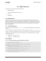
9.1
What is XMeshBase?................................................................................................... 75
9.2
XMeshBase Services ................................................................................................... 76
9.3
Building XMeshBase................................................................................................... 77
9.4
Using the Heartbeat ..................................................................................................... 78
10
XMesh Services ..................................................................................................................79
10.1
Health Statistics........................................................................................................ 79
10.2
Over-the-Air-Programming (OTAP)........................................................................ 82
10.3
OTAP using MoteConfig Utility .............................................................................. 89
10.4
Watch Dog ............................................................................................................... 97
10.5
Time Synchronization for Low Power ..................................................................... 97
11
XSniffer.............................................................................................................................102
11.1
Building and Starting XSniffer .............................................................................. 102
11.2
Using XSniffer ....................................................................................................... 102
12
MoteConfig .......................................................................................................................109
13
Appendix A: XMesh Constants ......................................................................................112
14
Appendix B: MICA FUSE SETTINGS .........................................................................115
15
Appendix C: TinyOS Settings and Scripts ....................................................................119
16
Appendix D: TinyOS Components.................................................................................121
17
Appendix E: Computing TOS Packet CRC ..................................................................123
Page ii
Doc.# 7430-0108-01 Rev. D
XMesh User’s Manual
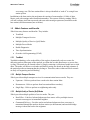
About This Document
The following annotations have been used to provide additional information.
; NOTE
Note provides additional information about the topic.
; EXAMPLE
Examples are given throughout the manual to help the reader understand the terminology.
3 IMPORTANT
This symbol defines items that have significant meaning to the user
WARNING
The user should pay particular attention to this symbol. It means there is a chance that physical
harm could happen to either the person or the equipment.
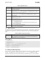
The following paragraph heading formatting is used in this manual:
1 Heading 1
1.1 Heading 2
1.1.1 Heading 3
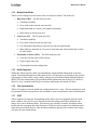
This document also uses different body text fonts (listed in Table 0-1) to help you distinguish
between names of files, commands to be typed, and output coming from the computer.
Table 0-1. Font types used in this document.
Font Type
Usage
Courier New Normal
Sample code and screen output
Courier New Bold
Commands to be typed by the user
Times New Roman Italic TinyOS files names, directory names
Franklin Medium Condensed
Doc.# 7430-0108-01 Rev. D
Text labels in GUIs
Page iii
XMesh User’s Manual
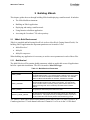
1 Introduction
This manual is intended for developers using Crossbow’s MoteWorks software platform. User’s
should have read or be familiar with the following:
•
MoteWorks Getting Started Guide.
•
TinyOS and nesC fundamentals
This chapter gives a general overview of the XMesh landscape and features. It includes:
•
Mesh Networking Fundamentals
•
XMesh Overview
•
What is a Multi-hop Network?
•
XMesh Network Landscape
•
XMesh Features and Benefits
1.1 Mesh Networking Fundamentals
Short-range networks based on wireless mesh networking architectures have evolved to enable
power efficient means for managing non-computer devices. Self-organizing mesh network
architectures have enabled new wireless machine-to-machine applications, including motiondetection sensors used on the battlefield; thermometers gauging the temperature of food products
and pharmaceuticals in transit; and medical devices monitoring patient vital signs.
Wireless sensor networks can be designed in a variety of ways to address different priorities and
make the appropriate technology trade-offs based on the requirements of the application. All
wireless mesh networking systems share a set of common requirements. These include:
•
•
•
•
•
Low power consumption — To support long-term operation, the power consumption of
the radio link must be minimized so that devices can be powered by compact, lightweight
batteries such as a coin cell battery for long periods of time.
Ease of Use — The network protocol allows the sensor network to initialize itself in a
highly ad hoc, self-organizing manner.
Scalability — The network must support the number of nodes required immediately and
must also be able to support future growth without causing exponential growth of
overhead.
Responsiveness — Topology discover and re-discovery must be efficient, especially for
applications where sensor nodes are mobile, such as in mobile machines or equipment or
for wearable sensors.
Range — It is more power efficient to emit low strength RF singles to travel a short
distance and be relayed a number of times than to transmit higher strength signals for
longer range. Repeaters form a network using a protocol that supports multi-hop routing
so that data packets can be relayed from one repeater to another when the mobile RF
terminal is far away from the base station.
Doc.# 7430-0108-01 Rev. D
Page 1
XMesh User’s Manual
•
•
•
Bi-directional communication — Communication between the gateway and sensor is
bi-directional to enable the base station to transmit signals to adjust certain operating
parameters in addition to receiving signals transmitting sensor data.
Reliability — While data reliability is always important, it becomes a critical
requirement for many applications, for example in medical monitoring.
Small module form factor— A very small form factor for the network modules is
needed so that endpoints can fit inside or attach easily to an existing device.
A robust networking protocol is needed to meet the above requirements as well as those of a
particular mesh networking design. The networking protocol provides support for the network's
topology and manages the routing of data through the network. In order for the application to
benefit from the promises of wireless sensor networking, the underlying protocol must support
all of these basic requirements.
1.2 Topologies
There are several architectures that can be used to implement wireless sensor network
applications, including star, mesh, and star-mesh hybrid. Each topology presents its own set of
challenges, advantages, and disadvantages. In order to understand the topologies, you need to be
familiar with the components of a wireless sensor network. These components include:
•
Endpoints — Integrate with sensors and actuators to capture the sensor data. For ZigBee
networks these are commonly referred to RFDs (Reduced Functional Devices). RFDs
cannot forward network messages upstream or downstream. XMesh-ELP Motes behave
as RFD devices.
•
Routers — Extend network area coverage, route around obstacles, and provide backup
routes in case of network congestion or device failure. In some cases, routers can also act
as endpoints. Routers are also referred to as full-function devices (FFD) in a ZigBee
network. All versions of XMesh, except XMesh-ELP Motes act as FFDs.
•
Gateways — Aggregate the data from the network, interface to the host, LAN, or the
Internet, and act as a portal to monitor performance and configure network parameters.
•
System Software — provides the networking protocol to enable the self-configuring,
self-healing ad hoc network.
Crossbow XMesh networks make no distinction between RFDs and FFDs (except for XMeshELP). All Motes can have integrated sensors and also forward messages upstream and
downstream.
Topology refers to the configuration of the hardware components and how the data is transmitted
through that configuration. The three most common topologies are star, mesh, and star-mesh
hybrid. Each topology presents its own set of challenges, advantages, and disadvantages and
each topology is appropriate under some circumstances, but may be unsuitable in others.
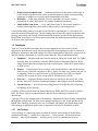
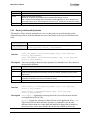
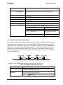
1.2.1
Star Topology
A star topology is a single-hop system in which all wireless sensor nodes are within direct
communication range — usually 30 to 100 meters — to the gateway. All sensor nodes are
identical — they are all endpoints — and the gateway serves to communicate data and
Page 2
Doc.# 7430-0108-01 Rev. D
XMesh User’s Manual
commands to the sensor endpoints. The gateway is also used to transmit data to a higher-level
control or monitoring system. The endpoints do not pass data or commands to each others; they
use the gateway as a coordination point (Figure 1-1).
Figure 1-1. Diagram showing a Star Topology
The star topology delivers the lowest overall power consumptions but is limited by the
transmission distance of the radio in each endpoint back to the gateway. There are also no
alternate communication paths to the endpoints. If path becomes obstructed, communication with
the associated endpoint will be lost.
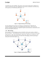
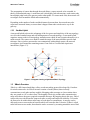
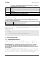
1.2.2
Mesh Topology
Mesh topologies are multi-hopping systems in which all wireless sensor nodes are identical —
they are all routers — and communicate with each other to hop data to and from the sensor nodes
and the gateway. This is the standard XMesh configuration. Unlike the star architecture, where
the nodes can only talk to the gateway, the nodes in a mesh topology can also hop messages
among other router nodes (Figure 1-2).
Figure 1-2. Diagram showing a Mesh Topology
Doc.# 7430-0108-01 Rev. D
Page 3
XMesh User’s Manual
The propagation of sensor data through the mesh allows a sensor network to be extended, in
theory to an unlimited range. A mesh network is also highly fault tolerant since each sensor node
has multiple paths back to the gateway and to other nodes. If a sensor node fails, the network will
reconfigure itself around the failed node automatically.
Depending on the number of nodes and the distances between them, the network may also
experience increased latency as sensor data is hopped from node to node on its way to the
gateway.
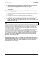
1.2.3
Star-Mesh Hybrid
A star-mesh hybrid seeks to take advantage of the low power and simplicity of the star topology,
as well as the extended range and self-healing nature of a mesh topology. A star-mesh hybrid
organizes sensor nodes in a star topology around routers which, in turn, organize themselves in a
mesh network. The routers serve both to extend the range of the network and to provide fault
tolerance. Since wireless sensor nodes can communicate with multiple routers, the network
reconfigures itself around the remaining routers if one fails or if a radio link experiences
interference (Figure 1-3).
Figure 1-3. Diagram showing a Hybrid Star/Mesh Topology
1.3
XMesh Overview
XMesh is a full featured multi-hop, ad-hoc, mesh networking protocol developed by Crossbow
for wireless networks. An XMesh network consists of nodes (Motes) that wirelessly
communicate to each other and are capable of hopping radio messages to a base station where
they are passed to a PC or other client. The hopping effectively extends radio communication
range and reduces the power required to transmit messages. By hopping data in this way, XMesh
can provide two critical benefits: improved radio coverage and improved reliability. Two nodes
do not need to be within direct radio range of each other to communicate. A message can be
delivered to one or more nodes in-between which will route the data. Likewise, if there is a bad
radio link between two nodes, that obstacle can be overcome by rerouting around the area of bad
Page 4
Doc.# 7430-0108-01 Rev. D
XMesh User’s Manual
service. Typically the nodes run in a low power mode, spending most of their time in a sleep
state, in order to achieve multi-year battery life.
XMesh is a software library, using the TinyOS operating system that runs on embedded devices
called Motes. Motes consist of a:
1. Microprocessor:
Atmel ATmega128 for MICA2, MICA2DOT and MICAz - ATmega128 has 128K of
flash memory, 4K of RAM, and 4K of EEPROM or
Atmel ATmega1281 for IRIS - ATmega1281 has 128K of flash memory, 8K of RAM,
and 4K of EEPROM.
2. Radio: a MICA2 radio at 916/433 MHz or MICAz / IRIS radio at 2.4 GHz.
3. Serial Flash: External flash storage memory to support OTAP (over-the-air
programming) and data logging.
4. UID: An integrated circuit that is programmed with a unique 64-bit identifier (for MICA2
and MICA2DOT).
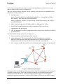
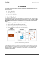
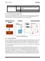
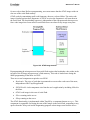
The entire XMesh network consists of (see Figure 1-4):
1. One or more Motes which participate in the network
2. A base station node. This is another MICA2 or MICAz mounted on a Crossbow
MIB510/520/600 interface board and programmed with XMeshBase application. It
manages the network and forwards data messages into and out of the mesh.
3. A PC, Stargate or other client which receives data and sends commands into the network.
Figure 1-4. XMesh Network Diagram
XMesh provides a TrueMesh networking service that is both self-organizing and self-healing (see
TrueMesh section below). XMesh can route data from nodes to a base station (upstream) or
downstream to individual nodes. It can also broadcast within a single area of coverage or
arbitrarily between any two nodes in a cluster. QOS (Quality of Service) is provided by either a
Doc.# 7430-0108-01 Rev. D
Page 5
XMesh User’s Manual
best effort (link level acknowledgement) and guaranteed delivery (end-to-end
acknowledgement). Also, XMesh can be configured into various power modes including HP
(high power), LP (low power), and ELP (extended low power).
The XMesh networking protocol has various options including low-power listening, time
synchronization, sleep modes, any-to-base and base-to-any routing. All Crossbow sensor and
data acquisition boards that can make up a wireless sensor network are supported with XMesh
enabled applications.
The XMesh network has the following features:
•
MICA2, MICA2DOT, and MICAz support.
•
Low power (typically less than 220 µA average current (without sensor board).
•
Network time synchronization to ± 1 msec.
•
Low power listening with an 8 times per second wake-up interval, allowing for rapid
message transfer across the network. The default sampling period is 3 minutes, although
many other sampling intervals are allowed.
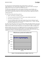
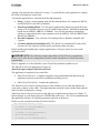
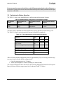
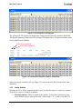
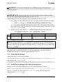
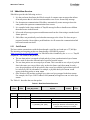
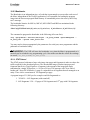
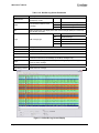
The XMesh network has been extensively tested both at indoor and outdoor locations. In a typical
indoor test, nodes are placed at every 300 sq ft. to cover a 10,000 sq ft facility. To simulate larger
distance between nodes, the radio transmit power was turned down to -6dBm. In outdoor tests,
nodes are spread across several acres of rugged terrain with an average density of one Mote per
10,000 sq ft and at full radio power. Statistical analysis across many deployments shows on
average greater than 90% of all traffic generated at any node will be collected at the base station
without the use of end-to-end acknowledgements (guaranteed delivery).
XMesh2 micaz upstream with end2end ack
120.00%
100.00%
Percentage
80.00%
Series1
60.00%
Series2
40.00%
20.00%
0.00%
0
10
20
30
40
50
60
Node ID
Figure 1-5. Percent Packet Delivery for 48 Mote, 72 Hour Test
Page 6
Doc.# 7430-0108-01 Rev. D
XMesh User’s Manual
1.4
XMesh Network Landscape
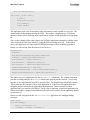
A wireless network deployment is composed of the three distinct software tiers:
1. The Mote Tier, where XMesh resides, is the software that runs on the cloud of sensor
nodes forming a mesh network. The XMesh software provides the networking algorithms
required to form a reliable communication backbone that connects all the nodes within
the mesh cloud to the server.
2. The Server Tier is an always-on facility that handles translation and buffering of data
coming from the wireless network and provides the bridge between the wireless Motes
and the internet clients. XServe and XOtap are server tier applications that can run on a
PC or Stargate. (Refer to XServe User’s manual)
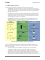
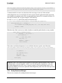
3. The Client Tier provides the user visualization software and graphical interface for
managing the network. Crossbow provides free client software called MoteView, but
XMesh can be interfaced to custom client software as well.
Figure 1-6. Software Framework for a Wireless Sensor Network
An XMesh sensor network system consists of multiple motes (MICA2/MICAz) and a base
station unit (MICA2/MICAz) installed on an interface board (eg. MIB520). This base station
Mote serves two purposes:
1. It acts as the Gateway between the Mote Tier and Server Tier. The base station
communicates with other motes over the radio, and with the server using serial
communication. In this way, the base station forms a bridge to send and receive
messages between a host system (PC and/or Stargate) and the rest of the mesh network.
2. It forms the network and directs all data messages from the Motes to itself. To other
Motes in the network, this base station Mote can forward messages to the PC (host) with
Doc.# 7430-0108-01 Rev. D
Page 7
XMesh User’s Manual
zero energy cost. The base station Mote is always identified as “node 0” in a single base
station system.
In addition to the base station, the mesh network consists of some number (1-100s) of other
Motes, each with a unique node identification number. This system of Motes, running XMesh,
will self-configure itself into a network and route radio messages upstream (from Motes to the
base station) and downstream (base to Motes).
1.5
XMesh Features and Benefits
XMesh has many features and benefits. They include:
•
TrueMesh
•
Mutliple Transport Services
•
Multiple Quality of Service (QoS) Modes
•
Multiple Power Modes
•
Health Diagnostics
•
Time Synchronization
•
Over-the-Air-Programming (OTAP)
1.5.1
TrueMesh
TrueMesh technology refers to the ability of the nodes to dynamically seek new routes for
delivering packets when parts of the network go offline due to radio interference or power dutycycling. A network may be formed ad-hoc by simply scattering a collection of nodes next to each
other. The nodes will discover each other and build a routing tree based on the link estimates of
the particular radio environment that they belong to. Therefore, nodes within an XMesh network
are truly self-organizing and self-healing.
1.5.2
Multiple Transport Services
XMesh provides multiple transport services for communication between nodes. They are:
•
Upstream – Delivers packets from a node to the base station Mote.
•
Downstream – Delivers packets from base station Mote to node(s)
•
Single Hop – Delivers packets to neighboring nodes only.
1.5.3
Multiple Quality of Service (QoS) Modes
XMesh provides multiple qualities of service modes. They are:
•
Best Effort – Link level acknowledgement where motes will try multiple times to
transmit a message to its immediate neighbor.
•
Guaranteed Delivery – Provides end-to-end acknowledgement where a message is
transmitted through the mesh to the base station (or downstream) and an acknowledge
message is then sent back to the originator.
Page 8
Doc.# 7430-0108-01 Rev. D
XMesh User’s Manual
1.5.4
Multiple Power Modes
XMesh can be configured to run in one of the several power modes. The modes are:
1. High Power (HP) – The HP mode provides:
•
TrueMesh capability
•
Every node in the network can route data
•
High bandwidth, low latency (full channel utilization)
•
Mote radios are always powered.
2. Low Power (LP) – The LP mode provides:
•
TrueMesh capability
•
Every node in the network can route data
•
Low bandwidth, high latency (ideal for low data rate applications)
•
Mote radios are normally in a low power sleep state and wake periodically to check
for radio traffic.
3. Extended Low Power (ELP) – The ELP mode provides:
1.5.5
•
Used only for end nodes of the network
•
Nodes cannot route data
•
Uses hybrid star mesh configuration
Health Diagnostics
Within the XMesh network, nodes can automatically transmit health information to the base
station. The health information includes data on how well the node is performing in the network
with regards to radio traffic, battery voltage, and parent’s node Radio Signal Strength Indicator
(RSSI). The base station Mote will forward the health information data to MoteView (Refer to
MoteView User’s manual) and XSniffer to monitor and diagnose the health of XMesh.
1.5.6
Time Synchronization
XMesh-LP support a network global time synchronization to ±1 msec. The time stamping is used
to synchronize radio messages but is also available to users to synchronize sensor measurements.
1.5.7
OTAP
XMesh supports Over-the-Air-Programming which allows users to reprogram all nodes in the
mesh with new code. OTAP uses a directed downstream strategy that allows different code
images to be sent to different Motes. This allows users to deploy networks of multiple sensor
boards and only reprogram the units of interest. OTAP also uses a promiscuous listening mode;
motes that can overhear the new code download, and know that they also need the same image,
will store the code transmissions.
Doc.# 7430-0108-01 Rev. D
Page 9
XMesh User’s Manual
2 Building XMesh
This chapter guides the user through building XMesh and deploying a small network. It includes:
•
The XMesh build environment.
•
Building an XMesh application.
•
Deploying and testing a small network.
•
Using binaries to build an application.
•
Accessing the Crossbow CVS code repository
2.1
XMesh Build Environment
XMesh is compiled and built using MoteWorks (refer to MoteWorks Getting Started Guide). For
building XMesh applications the important parameters are located in 3 files.
•
MakeXbowlocal
•
Makefile
•
Makefile.component
When building any application it is necessary to set the correct parameters in each of these files.
2.1.1
MakeXbowlocal
The MakeXbowlocal file contains global parameters which are applicable across all applications
built for a particular installation. The file is located in /MoteWorks/apps.
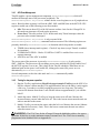
Table 2-1. MakeXbowlocal Parameters
Parameter
RADIO_CLASS
Description
This parameter defines the radio band in which the network communicates for
MICA2/MICA2DOT radios. The operating band is defined by the mote’s radio
hardware. This should correspond to the label on the board. The available
classes for Mica2 and Mica2Dot are 916 MHz, 433 MHz and 315 MHz.
RADIO_CHANNEL
This parameter defines the radio channel the network is operating on. Each
band has multiple channels upon which it can operate. The user should
choose a channel which is not being used by other wireless devices in the
network (including other sensor networks). See table below for MICAz
settings.
RADIO_POWER
This parameter defines the power level for the radio.
DEFAULT_LOCAL_GROUP
The local group is the group id upon which each node in your network will
communicate on. The group id is a way for multiple networks to operate on
the same radio band and channel yet filter communication by group id.
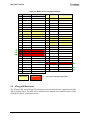
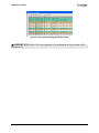
The Table 2-2 shows the available radio channels for the MICAZ 802.15.4 radio. USA/FCC &
Canada regions have 27 total channels allocated. Channels 11 to 26 are in the 2.4 GHz band.
Page 10
Doc.# 7430-0108-01 Rev. D
XMesh User’s Manual
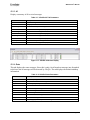
Table 2-2. IEEE 802.15.4 Channels. All frequencies are in GHz.
2.1.2
Channel
Lower Frequency
Central Frequency
Upper Frequency
11
2.404
2.405
2.406
12
2.409
2.410
2.411
13
2.414
2.415
2.416
14
2.419
2.420
2.421
15
2.424
2.425
2.426
16
2.429
2.430
2.431
17
2.434
2.435
2.436
18
2.439
2.440
2.441
19
2.444
2.445
2.446
20
2.449
2.450
2.451
21
2.454
2.455
2.456
22
2.459
2.460
2.461
23
2.649
2.650
2.651
24
2.469
2.470
2.471
25
2.474
2.475
2.476
26
2.479
2.480
2.481
Makefile
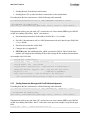
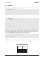
The Makefile contains build specific parameters. Most importantly it defines high level services
which should be included for the particular application by way of a list of goals. The file is
located in /MoteWorks/apps/<specific app name>/. An example Makefile is
Users can either edit the Makefile for these parameters or include them in the command line. The
command line will override any parameters set in the Makefile.
; EXAMPLE
•
To force XMesh-HP for a MICAz:
make micaz route,hp
•
To force a base station build for a MICAz and XMesh-HP :
make micaz base route,hp
An example of a Makefile is:
include Makefile.component
include ../../../MakeXbowlocal
# Automatically add certain command-line goals:
GOALS += basic freq route,hp
Doc.# 7430-0108-01 Rev. D
Page 11
XMesh User’s Manual
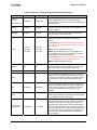
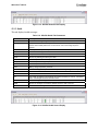
Table 2-3. Makefile Services
Service
Description
basic
Responsible for including the standard Crossbow services. This service should be included
in all XMesh applications.
freq
Sets the radio channel for the application. This feature acts as an application specific
override of the RADIO_CHANNEL parameter set in the MakeXbowlocal file. Usage is:
freq,<freq> or freq,<channel #>
group
Sets the group id for the application and acts as an override of the
DEFAULT_LOCAL_GROUP parameter set in the MakeXbowlocal file. Usage is:
group,<group #>.
power
Sets the radio power and acts as an override of the RADIO_POWER parameter set in the
MakeXbowlocal file. Usage is:
power,<power #>.
route
Sets the XMesh power operating mode. Usage is: route,<operating mode>.
The available operating modes are:
• hp to build XMesh high power.
•
lp to build XMesh low power. This will build the time synchronized MICA2 mesh or
asynchronous MICAZ mesh.
• elp to build XMesh extended low power
base
2.1.3
The base goal sets the application image as the base station node in XMesh. This should
only be used for building XMeshBase.
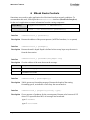
Makefile.component
The Makefile.component contains application specific parameters. The parameters defined in the
component file are applicable to the particular application and are provided by the application
itself.
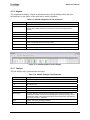
Table 2-4. Makefile.component parameters
Parameter
Description
COMPONENT
The component parameter tells the build system which application is being made and also
can include #defines to configure XMesh. The component listed here should be the top
level application component in the application
; EXAMPLE
COMPONENT=ELPTest
SENSORBOARD=micasb
INCLUDES+= -I../../../../tos/lib/XMesh2_TestSuite
#DEFINES += -DROUTE_UPDATE_INTERVAL=15000
#DEFINES += -DTOSH_DATA_LENGTH=50
DEFINES += -DDATA_REPORT_RATE=10
2.2
Building an XMesh Application
In this section we will build a simple XMesh-HP application to demonstrate building a multihop
network. The application we will develop is the XMeshCountToLeds application. In this
application each node in the network will increment its individual count every one second and
Page 12
Doc.# 7430-0108-01 Rev. D
XMesh User’s Manual
send the value back the base station for viewing. To verify that the count application is working
the LEDs will display the count value.
To build this application we will need the following equipment:
•
•
•
•
Motes: At least 3 motes running under similar radio platforms, for example the MICA2
and MICA2DOT or the MICAz platform.
Mote Programming Board: You will need a programming board to program the motes
and to act as an interface between your PC and the mote network. Potential programming
boards are the MIB510, MIB520, or MIB600. You will also need the accompanying
cabling to connect the board to your computer (serial for MIB510, USB for MIB520 and
Ethernet for MIB600).
Personal Computer: You will need a PC running Linux or Windows installed with
Cygwin.
Crossbow MoteWorks Installation CD: The MoteWorks installation CD comes with
necessary PC side software to build, install, and analyze Mote networks.
Before building and installing the example application we will give a brief overview of the
application itself.
3 IMPORTANT: The following assumes knowledge of TinyOS/nesC programming.
Please refer to MoteWorks Getting Started Guide for more information on TinyOS and nesC
programming.
Refer to Appendix C to check that the correct TinyOS environment variables are set.
The XMeshCountToLeds application is located in
MoteWorks/apps/examples/XMeshCountToLeds.
The application is composed of two main files:
•
XMeshCountToLeds.nc: Contains component wiring information and shows how the
application connects to the XMesh multihop networking service.
•
XMeshCountToLedsM.nc : Contains the application
The XMeshCountToLedsM.nc file increments a count variable every second and displays the
count value in binary on the LEDs. The application then sends the count variable along with the
node id to the base station for viewing.
XMesh provides a rich set of services to send and receive application messages (see Chapter 5).
In this example we will display the basic UPSTREAM send service. The service implemented in
this application will have no reliability guarantees and runs at full power.
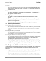
Below are code excerpts from XMeshCountToLedsM.nc:
void displayCount(uint16_t value){
if (value & 1) call Leds.redOn();
else call Leds.redOff();
if (value & 2) call Leds.greenOn();
else call Leds.greenOff();
if (value & 4) call Leds.yellowOn();
Doc.# 7430-0108-01 Rev. D
Page 13
XMesh User’s Manual
else call Leds.yellowOff();
}
event result_t Timer.fired(){
g_count++;
displayCount(g_count);
post sendMsg();
return SUCCESS;
}
The application runs a one second timer which increments a count variable on every fire. The
count variable is then displayed using the LEDs. The number is displayed as a 3 bit binary
number with the yellow led being most significant bit and the red led being the least significant
bit.
Once we have displayed the count value to the LEDs the application attempts to send the count
value and node id to the base station PC using the XMesh multihop network. As described
above, this application will only send UPSTREAM messages with no reliability guarantees.
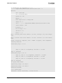
Below is a code excerpt from the XMeshCountToLeds.nc :
implementation{
components
Main,XMeshCountToLedsM,LedsC,TimerC,XMeshRouter;
StdControl = XMeshCountToLedsM.StdControl;
Main.StdControl -> TimerC.StdControl;
Main.StdControl -> XMeshRouter.StdControl;
Main.StdControl -> XMeshCountToLedsM.StdControl;
XMeshCountToLedsM.Leds -> LedsC.Leds;
XMeshCountToLedsM.Timer -> TimerC.Timer[unique("Timer")];
XMeshCountToLedsM.MhopSend -> XMeshRouter.MhopSend[10];
}
The XMesh service is implemented by the XMeshRouter component. The routing component
provides a sending interface in MhopSend which sends packets into the network. A receiving
interface is also implemented but will be described later. Each application which links into the
XMesh send interface attaches with its own application id. XMesh uses this application id to
multiplex packets from different applications in the network. In this example we chose
application id 10 to interface with XMesh. The id value is important, in that each application on
XMesh should have a unique id and both the send and receive interface for an application should
use the same id.
Below are code excerpts from the XMeshCountToLeds application for sending multihop
messages.
TOSMsg g_msg;
task void sendMsg(){
uint16_t bufferLength = 0;
CountMsg_t* countMsg = (CountMsg_t*)
Page 14
Doc.# 7430-0108-01 Rev. D
XMesh User’s Manual
MhopSend.getBuffer(&g_msg,&bufferLength);
countMsg->nodeId = TOS_LOCAL_ADDRESS;
countMsg->nodeCount = g_count;
call MhopSend.send(
BASE_STATION_ADDRESS,
MODE_UPSTREAM,&g_msg, sizeof(CountMsg_t));
}
The basic messaging structure in TinyOS is the TOSMsg object. The application declares a
TOSMsg which it will fill with application specific messaging information. In this case the
information is the local node id and the current count value. Though the message object is
owned by the application, XMesh will fill out the initial portion of the message with its own
mesh information. To retrieve the area of message buffer that is for use by the application the
code uses the MhopSend.getBuffer() method. The method returns a pointer to the location
in the buffer where the application can insert its information.
Once the packet is filled out the application must hand the message to XMesh to send. The
MhopSend.send() method provides the sending interface. The application provides the
address of the receiver, in this case the BASE_STATION_ADDRESS. It also provides the send
mode. In this application we are using the UPSTREAM mode with no reliability guarantees as
shown by the parameter MODE_UPSTREAM. After XMesh has attempted send the message it
informs the application of the result through the MhopSend.sendDone() event.
An example of the MakeXbowlocal file for this application could have parameters shown in
Table 2-5.
Table 2-5. MakeXbowlocal Parameters
Parameters
MICA2 / MPR600
MICAz / MPR2600
IRIS / M2110
RADIO_CLASS
916
N/A
N/A
RADIO_CHANNEL
10
13
11
RADIO_POWER
0xff
TXPOWER_0DBM
TXPOWER_3_2DBM
DEFAULT_LOCAL_GROUP
0x3
0x3
0x3
An example of the Makefile for this application could be:
# $Id: Makefile,v 1.2 2005/11/03 21:56:20 rkapur Exp $
include Makefile.component
include ../../MakeXbowlocal
# Automatically add certain command-line goals:
GOALS += basic freq route,hp
TOSMAKE_PATH = ${TOSROOT}/contrib/xbow/tools/make
include ${TOSROOT}/tools/make/Makerules
The Makefile.component for this application is:
Doc.# 7430-0108-01 Rev. D
Page 15
XMesh User’s Manual
COMPONENT=XMeshCountToLeds
MSG_SIZE = 49
Once all the correct parameters are set for an application the build process can be started by
executing the make command from the application directory. The make command has the
following parameters:
make <mote platform> binlink,none (build from source code)
make <mote platform> hp
(build from XMesh/Radio binaries)
The <mote platform> corresponds to the hardware platform:
mica2
mica2dot
micaz
iris
3 IMPORTANT: If the default ROUTE_UPDATE_INTERVAL has been changed make
sure the Makefile.Component for both the application and XMeshBase are the same for this
parameter.
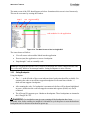
At the end of the build the code space (ROM) and variable storage memory (RAM) allocation of
the application will be displayed (see below). It is important to make sure that the application
does not consume too much RAM otherwise there may not be enough space for the stack and the
code can crash.
When using the ATmega128 there are 4096 bytes of RAM. The maximum RAM usage should
not exceed 3750 bytes.
Once the application has been built the motes can be programmed. To install an application to
the mote users need a programming board connected to their computer. Available programming
boards and their connections are:
•
•
•
MIB510 with serial connection
MIB520 with USB connection
MIB600 with Ethernet connection
To install an application onto the mote, attach it to the programming board and connect the
programming board to the PC. Once connected, program the mote using the GNU make system.
Page 16
Doc.# 7430-0108-01 Rev. D
XMesh User’s Manual
make <mote platform> install,<node_id> mib510|mib510|mib600, <device
location>
The <mote platform> is defined above. The <node id> parameter is the node id you wish to
assign. The value zero is reserved for the base station. Finally you specify the type of
programming board connected to the mote and the location of the device. The <device location>
is determined by your operating system and whether you have a USB or serial connection.
The ATmega128’s internal fuses must also be correctly set. This can be done using the uisp.exe
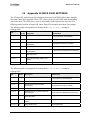
in the application directory or the fuses script. Refer to Appendix B for the correct fuse settings.
For XMesh-HP the default fuse setting are used. For XMesh-LP the JTAG fuse must be disabled
and the internal oscillator enabled.
WARNING: The correct ATmega128 fuses must be set. Refer to Appendix B.
Programming the base station (Refer to Chapter 9)
Compile and program a Mote (as Mote address 0) with the application in
/MoteWorks/apps/XMesh/XMeshBase as
make <mote platform> base route,hp
Programming a Sniffer Mote (Refer to Chapter 11)
Compile and program a sniffer Mote with the application in /MoteWorks/apps/general/XSniffer
make <mote platform>
2.3
Deploying the Network
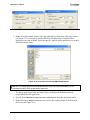
Once the motes are deployed and powered use XSniffer to monitor the network activity (refer to
Section 11.2). This allows users to monitor the mesh formation, route update packets, and all
upstream and downstream traffic. After you have seen the routing packets being exchanged using
XSniffer, you are able to view the individual packets arriving through the base station. Using
XServe or a standard terminal program (e.g. HyperTerminal), you can view the raw data packets
coming from the base station. Refer to Chapter 9 for more information on the serial data
packets.
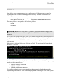
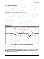
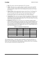
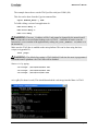
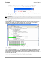
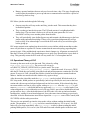
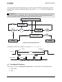
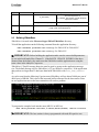
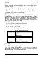
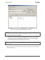
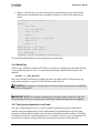
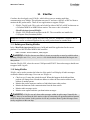
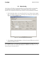
The screen shot in Figure 2-1 shows the mesh formation of a single Mote:
1. The initial transmissions from the mote are all broadcast (bcast) transmissions since the
mote has not yet joined the mesh. This occurs until the 1.11.24.190 time.
2. At 1.11.19.904 the base station transmits a route update message. The message tells the
mote that the base station can hear it.
3. At 1.11.24.060 the mote transmits a route update message telling the base that the mote
can hear it.
4. At 1.11.24.190 the mote has joined the mesh and now directs its messages directly to the
base.
Doc.# 7430-0108-01 Rev. D
Page 17
XMesh User’s Manual
2
3
1, 4
Figure 2-1. Screenshot displaying XSniffer Output
2.4
Using Binaries
Crossbow provides XMesh in the form of binary components which allow users to link to XMesh
object files and use services provided therein. The default make commands will use these
binaries. For example:
make micaz route,hp
builds the MICAz high power mesh using the binaries files.
The XMesh binaries are located /Moteworks/tos/lib/XMeshBin
Page 18
Doc.# 7430-0108-01 Rev. D
XMesh User’s Manual
3 Hardware Overview
This section gives a general overview of:
•
MICAz and MICA2 hardware platforms.
•
ATmega128 resources
•
Using ATmega128 resources
•
Low power operation
•
Optimizing for battery operation
•
Hardware debugging techniques
3.1
Hardware Platforms
The table below summarizes the core elements of the MICAz, MICA2 and IRIS hardware
platforms:
Table 3-1. Hardware Platform Summary
Platform
MICAz
MICA2
IRIS
Microprocessor
ATmega128L
ATmega128L
ATmega1281
Radio
CC2420 (2.4GHz)
CC1000 (433MHz,916MHz)
RF230 (2.4GHz)
External Serial
Flash
AT45DB041
512 Kbytes
The serial flash can be used for over-the-air-programming (OTAP) and/or data logging
Unique ID
(integrated
circuit)
DS2401P
51-Pin
Connector
Yes, except for OEM modules
64-bit
This chip contains a unique 64 bit identifier.
This connector brings out most of the ATmega128L signal
Doc.# 7430-0108-01 Rev. D
Page 19
XMesh User’s Manual
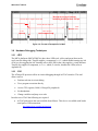
Antenna
MMCX
Serial
ID
ATMega128L
µcontroller
Analog I/O
Digital I/O
DSSS, 802.15.4
Radio
51-Pin Expansion
Logger
Flash
L
E
D
s
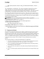
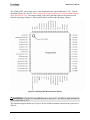
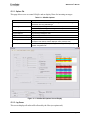
Figure 3-1. The MICAz Hardware Architecture
The Table 3-2 shows the 51-pin expansion connector for the MICAz / IRIS and the pins that are
available for user application.
Page 20
Doc.# 7430-0108-01 Rev. D
XMesh User’s Manual
Table 3-2. MICAz/ IRIS 51-pin Connector Interface
Pin
Name
Description
Pin
Name
Description
1
GND
Ground
27
g
UART_RXDO
UART_0 Receive
2
VSNR
Sensor Supply
28g
UART_TXDO
UART_0 Transmit
3
INT3
GPIO
29
PWO
GPIO/PWM
4
INT2
GPIO
30
PW1
GPIO/PWM
5
INT1
GPIO
31
PW2
GPIO/PWM
INT0
GPIO
32
PW3
GPIO/PWM
6
7
CC_CCA
Radio Signal
33
PW4
GPIO/PWM
8g
LED3
Green LED
34
PW5
GPIO/PWM
9
g
LED2
Yellow LED
35
PW6
GPIO/PWM
10g
LED1
Red LED
36g
ADC7
ADC CH7, JTAG TDI
11
RD
GPIO
37
g
ADC6
ADC CH6, JTAG TDO
12
WR
GPIO
38
g
ADC5
ADC CH5, JTAG
13
ALE
GPIO
39g
ADC4
ADC CH4, JTAG
14
PW7
GPIO
40
ADC3
GPIO/ADC CH3
15
USART1_CLK
USART1 Clock
41
ADC2
GPIO/ADC CH2
16gg
PROG_MOSI
Serial Program MOSI
42
ADC1
GPIO/ADC CH1
17
gg
PROG_MISO
Serial Program MISO
43
ADC0
GPIO/ADC CH0
18gg
SPI_CLK
SPI Serial Clock
44
THERM_PWR
Temp Sensor Enable
19
USART1_RXD
USART1 Receive
45
THRU1
Thru Connect 1
20
USART1_TXD
USART1 Transmit
46
THRU2
Thru Connect 2
21
I2C_CLK
I2C Bus Clock
47
THRU3
Thru Connect 3
22
I2C_DATA
I2C Bus Data
48gg
RSTN
Reset (Neg.)
23
PWM0
GPIO/PWM0
49
PWM1B
GPIO/PWM1B
24
PWMIA
GPIO/PWM1A
50
VCC
Digital Supply
25
AC+
GPIO/AC+
51
GND
Ground
26
AC-
GPIO/AC-
g
gg
Shared use
DO NOT use
gg
For in-system programming (“ISP”)
The Table 3-3 shows the 51-pin expansion connector for the MICA2 and the pins that are
available for user application:
Doc.# 7430-0108-01 Rev. D
Page 21
XMesh User’s Manual
Table 3-3. MICA2 51-pin Connector Interface
Pin
Name
Description
Pin
Name
Description
1
GND
Ground
27g
UART_RXDO
UART Receive
2
VSNR
Voltage (battery
28
UART_TXDO
UART Transmit
3
INT3
GPIO
29
PWO
GPIO/PWM
4
INT2
GPIO
30
PW1
GPIO/PWM
5
INT1
GPIO
31
PW2
GPIO/PWM
6
INT0
GPIO
32
PW3
GPIO/PWM
7g
BAT_MON
Battery Voltage Monitor
33
PW4
GPIO/PWM
8g
LED3
Green LED
34
PW5
GPIO/PWM
9g
LED2
Yellow LED
35
PW6
GPIO/PWM
10g
LED1
Red LED
36g
ADC7
GPIO/ADC CH7, JTAG
11
RD
GPIO
37
g
ADC6
GPIO/ADC CH6, JTAG
12
WR
GPIO
38g
ADC5
GPIO/ACD CH5, JTAG
13
ALE
GPIO
39
ADC4
GPIO/ADC CH4, JTAG
14
PW7
GPIO
40
ADC3
GPIO/ADC CH3
15
USART_CLK
USART Clock
41
ADC2
GPIO/ADC CH2
16gg
PROG_MOSI
Programmer Pin
42
ADC1
GPIO/ADC CH1
17gg
PROG_MISO
Programmer Pin
43
ADC0
GPIO/ADC CH0
18
SPI_CLK
Radio Clock
44
THERM_PWR
GPIO
g
19
USART1_RXD
USART1 Receive
45
THRU1
Thru User Connect
20
USART1_TXD
USART1 Transmit
46
THRU2
Thru User Connect
21
I2C_CLK
I2C Bus Clock
47
THRU3
Thru User Connect
22
I2C_DATA
I2C Bus Data
48
23
PWMIO
GPIO
49
24
PWMIA
GPIO
25
AC+
GPIO
26
AC-
GPIO
g
3.2
gg
g
Shared use
DO NOT use
gg
RSTN
Micro Processor Reset
PWM1B
GPIO
50
VCC
Voltage (battery)
51
GND
Ground
gg
For in-system programming (“ISP”)
ATmega128 Resources
The ATmega128L and ATmega1281 microprocessors run both the user’s application and the
XMesh protocol stack. The table below summarizes the internal and external resources of the
ATmega128 family of microprocessors:
Page 22
Doc.# 7430-0108-01 Rev. D
XMesh User’s Manual
Table 3-4. Resources of the ATmega128 family Microprocessors
Resource
ATmega1281
Information
128K Bytes
128K Bytes
This memory stores the application code. It is programmed
through an MIB base station or using OTAP. When
reprogrammed, the entire memory is erased except for the
bootloader section.
SRAM
4K Bytes
8K Bytes
This memory section is used to store user application
parameters, XMesh variables and TinyOS variables. It also
contains the stack.
EEPROM
4K Bytes
4K Bytes
This memory is used to store persistent values such as
mote_id, group_id, radio channel etc.
Program
Memory
ATmega128L
(Flash Memory)
TIMER0: In ATmega128L (8 bit) is used by TinyOS and is
available to the user via the standard TinyOS clock
services.
Timers
4 Timers,
4 Timers,
In ATmega1281 (8 bit) is not available to the user on the
IRIS, it is used by the TinyOS radio stack and cannot be
used otherwise
two 8 bit,
two 8 bit,
TIMER1: (16 bit) is available to the user
two 16 bit
two 16 bit
TIMER2: In ATmega128L (8 bit) is only available to the
user on the MICA2. For MICAz it is used by the TinyOS
radio stack and cannot by used otherwise.
In ATmega1281 (8 bit) is used by TinyOS and is available
to the user via the standard TinyOS clock services..
TIMER3: (16bit) is available to the user.
SPI Bus
n/a
n/a
The SPI bus is reserved exclusively for the radio interface
and is not available for user applications. The SPI bus is
also used during reprogramming by the MIB units.
I2C Bus
n/a
n/a
This is a standard serial interface to many sensors
2
The processor has two UARTs that can be run in either an
asynchronous or synchronous mode. UART0 is used for
base station communication. UART1 is available to users.
The control pins for this uart are shared with the serial
flash.
8 channels
There is a 10 bit ADC available for users. On MICA2 one
channel is allocated for the radio’s RSSI. The ADC inputs
are also used for JTAG so users should try to use other
ADC inputs if possible if they wish to use the JTAG
capability.
UART
ADC
2
8 channels
GPIO
There are many general purpose I/O lines available. Some
of these support additional functionality (see ATmega128L
or ATmega1281 manual as appropriate)
External Clock
(High Speed)
This crystal speed is chosen to generate correct UART
baud rates (57.6K baud). It is only needed for base station
Motes that communicate over the UART or other user
applications that communicate to external serial devices.
Normally a non-base station mote is fuse programmed to
use an internal 8 MHz clock as this clock has a faster startup time and reduces the overall power consumption for a
low-power mesh. The high speed clock is off when the
MICA is sleeping.
7.3728 MHz
Doc.# 7430-0108-01 Rev. D
7.3728 MHz
Page 23
XMesh User’s Manual
External Clock
(Low Speed)
3.3
32 kHz
32 kHz
In ATmega128L, this clock is used for TinyOS timing
(TIMER0 in ATmega128L and TIMER2 in ATmega1281). It
is always running even when the mote is sleeping as it’s
used to wake-up the mote after the required sleep interval.
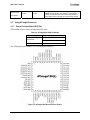
Using ATmega Resources
3.3.1
General Port Input/Output (GPIO) Pins
GPIO enables direct control of individual CPU pins:
Table 3-5. ATmega128L GPIO Pin Modes
Mode
Output Mode
Input Mode
Action
Set a pin high
Clear a pin to low
Read a pin’s state (high or low)
The ATmega has ports named A-G, each with pins named 0-7.
Figure 3-2. ATmega128L Microprocessor Pinout
Page 24
Doc.# 7430-0108-01 Rev. D
XMesh User’s Manual
The ATmega128L can operate up to 6 volts maximum power input and down to 2.4V. Typical
operation is from 3.6V to 2.4V. The ATmega1281V can operate up to 6 volts maximum voltage
input and down to 1.8V. The output voltage of the GPIO and other pins on the processor will
track the operating voltage (i.e. when turned on they will be at the operating voltage).
Figure 3-3. ATmega1281 Microprocessor Pinout
WARNING: The MICA2 and MPR600 radio is rated to 5V. The MICAz, IRIS and M2110
radio is rated only to 3.6V.
The maximum output current per I/O pin is 40 mA and the maximum current for the processor is
200 mA.
Doc.# 7430-0108-01 Rev. D
Page 25
XMesh User’s Manual
3.3.2
UARTs
The ATmega128 has two UART ports, UART0 and UART1. They can operate in both an
asynchronous and synchronous (using a clock) mode. The external clock for the MICA2 and
MICAz use a 7.3228 MHz oscillator which generates precise timing for these UARTs to support
high baud rates.
WARNING: The internal RC oscillator does not support high baud rates. Check the
ATmega128 manual.
UART0 is used by the base station mote for communication to a client device and configured as
the default I/O serial communication port by TinyOS (see XMeshBase chapter). UART1 is
available to users. The UART transmit and receive pins are shared with the serial flash which is
also used by OTAP (see XMesh Services ). If the mote is communicating with another serial
device through UART1 users must design the interface so that the external device’s transmit pin
(which would be connected to UART1’s receive pin) defaults to a high impedance state on reset.
Otherwise OTAP will not be able to access the serial flash.
WARNING: UART1’s transmit and receive pins are shared with the external serial flash
chip which is used for OTAP.
3.3.3
ADC
The ATmega128 has an internal 10 bit ADC which gives a resolution of 1 part in 1024 (0.1%).
The diagram below shows the connection to the ATmega128 pins. ADC channels 4-7 share the
JTAG TCK, TMS, TDO and TDI pins. If users want to interface analog sensors to these channels
and use JTAG, use a 1K-10K resistor between the output of the sensor and input to the ADC
channel so that the sensor output will not interfere with JTAG. When JTAG is operational these
channels cannot measure sensor signals.
Some of the ADC channels are dedicated to on board peripherals for the MICA2. ADC0 is used
to measure the RSSI (RF signal strength) from the Chipcon1000 radio and is not available. Also,
ADC1 is wired to a thermistor for temperature measurements but this channel can be shared with
another analog input.
Page 26
Doc.# 7430-0108-01 Rev. D
XMesh User’s Manual
The ADC uses the battery voltage as a full scale reference. This means the full scale of the ADC
(10 bit or 1023) is proportional to the battery voltage. For example, when the battery voltage is at
3.2V an ADC value of 1023 will be measure for a full scale voltage input voltage of 3.2V. But
when the battery voltage changes to 2.7 volts the full scale will now correspond to this battery
voltage.
3.3.4
SPI Bus
The SPI ports are master/slave synchronous serial ports. The SPI bus on both the MICA2 and
MICAz are dedicated to the radio interfaces. They are also used during programming to load
code.
3.3.5
I2C
This port is a low speed serial interface that supported by many sensor and devices. It is available
to users and supported by several Crossbow sensor boards.
3.3.6
The hardware.h File
In the /MoteWorks/tos/platform directory there are other directories for each hardware platform
(such as MICAz, MICA2) supported by MoteWorks. This file mainly maps the processors I/O
pins to signal names used by the application and TinyOS code. For example:
TOSH_ASSIGN_PIN (RED_LED, A, 2);
assigns the red led control pin of the ATmega128 (Port A, Pin2) to the name RED_LED. This
allows the red led to called by avr functions (see below) directly within the user’s code.
Processor pins can also be remapped using an alias statement:
TOSH_ALIAS_PIN (name, other_name)
TinyOS provides several macros to set these pins as described in Table 3-6.
Table 3-6. TinyOS Macro for I/O Pins
MACRO
Action
TOSH_SET_##name##_PIN()
Set the named output pin to high
TOSH_CLR_##name##_PIN()
Set the named output pin to low
TOSH_READ_##name##_PIN()
Read the named input pin
Doc.# 7430-0108-01 Rev. D
Page 27
XMesh User’s Manual
MACRO
Action
TOSH_MAKE_##name##_OUTPUT() Define the pin as an output
TOSH_MAKE_##name##_INPUT()
Define the pin as an input
; EXAMPLE
An example of using these macros is:
TOSH_ASSIGN_PIN(RED_LED, A, 2);
TOSH_MAKE_RED_LED_OUTPUT();
TOSH_SET_RED_LED_PIN();
WARNING: The _SET_ command sets the ATmega128 pin high. This turns off the LED.
The _CLR_ macro turns on the LED. Consult the schematics that explain how to turn on/off the
peripherals.
3.3.7
Interrupts
In the AVR-LIBC environment, convenient macros are predefined to point to interrupt routines
with predetermined names. By using the appropriate name, routines will be called when the
corresponding interrupt occurs. The ATmega128 library provides a set of default interrupt
routines as shown in Table 3-7 and Table 3-8 for ATmega128L and ATmega1281 respectively.
Table 3-7. ATmega128L Interrupt Routines
Interrupt Name
Description
SIG_INTERRUPT0
External Interrupt0
SIG_INTERRUPT1
External Interrupt1
SIG_INTERRUPT2
External Interrupt2
SIG_INTERRUPT3
External Interrupt3
SIG_INTERRUPT4
External Interrupt4
Named INT0 on expansion conn.
SIG_INTERRUPT5
External Interrupt5
Named INT1 on expansion conn.
SIG_INTERRUPT6
External Interrupt6
Named INT2 on expansion conn.
SIG_INTERRUPT7
External Interrupt7
Named INT3 on expansion conn.
SIG_OUTPUT_COMPARE2
Output Compare2 Interrupt
SIG_OVERFLOW2
Overflow2 Interrupt
SIG_INPUT_CAPTURE1
Input Capture1 Interrupt
SIG_OUTPUT_COMPARE1A
Output Compare1(A) Interrupt
SIG_OUTPUT_COMPARE1B
Output Compare1(B) Interrupt
SIG_OVERFLOW1
Overflow1 Interrupt
SIG_OUTPUT_COMPARE0
Output Compare0 Interrupt
SIG_OVERFLOW0
Overflow0 Interrupt
Page 28
Notes
Doc.# 7430-0108-01 Rev. D
XMesh User’s Manual
Interrupt Name
Description
SIG_SPI
SPI Interrupt
SIG_UART_RECV UART(0)
Receive Complete Interrupt
SIG_UART1_RECV UART(1)
Receive Complete Interrupt
SIG_UART_DATA UART(0)
Data Register Empty Interrupt
SIG_UART1_DATA UART(1)
Data Register Empty Interrupt
SIG_UART_TRANS UART(0)
Transmit Complete Interrupt
SIG_UART1_TRANS UART(1)
Transmit Complete Interrupt
SIG_ADC ADC
Conversion complete
SIG_EEPROM
Eeprom ready
SIG_COMPARATOR
Analog Comparator Interrupt
Notes
Table 3-8. ATmega1281 Interrupt Routines
Interrupt Name
Description
SIG_INTERRUPT0
External Interrupt0
SIG_INTERRUPT1
External Interrupt1
SIG_INTERRUPT2
External Interrupt2
SIG_INTERRUPT3
External Interrupt3
SIG_INTERRUPT4
External Interrupt4
Named INT0 on expansion conn.
SIG_INTERRUPT5
External Interrupt5
Named INT1 on expansion conn.
SIG_INTERRUPT6
External Interrupt6
Named INT2 on expansion conn.
SIG_INTERRUPT7
External Interrupt7
Named INT3 on expansion conn.
SIG_PIN_CHANGE0
Pin Change Interrupt Request0
SIG_PIN_CHANGE1
Pin Change Interrupt Request1
SIG_PIN_CHANGE2
Pin Change Interrupt Request2
SIG_WATCHDOG_TIMEOUT
Watchdog Time-out Interrupt
SIG_OUTPUT_COMPARE2A
Output Compare2(A) Interrupt
SIG_OUTPUT_COMPARE2B
Output Compare2(B) Interrupt
SIG_OVERFLOW2
Overflow2 Interrupt
SIG_INPUT_CAPTURE1
Input Capture1 Interrupt
SIG_OUTPUT_COMPARE1A
Output Compare1(A) Interrupt
SIG_OUTPUT_COMPARE1B
Output Compare1(B) Interrupt
SIG_OUTPUT_COMPARE1C
Output Compare1(C) Interrupt
SIG_OVERFLOW1
Overflow1 Interrupt
SIG_OUTPUT_COMPARE0A
Output Compare0(A) Interrupt
Doc.# 7430-0108-01 Rev. D
Notes
Page 29
XMesh User’s Manual
Interrupt Name
Description
SIG_OUTPUT_COMPARE0B
Output Compare0(B) Interrupt
SIG_OVERFLOW 0
Overflow0 Interrupt
SIG_SPI
SPI Interrupt
SIG_USART0_RECV
UART(0)Receive Complete Interrupt
SIG_USART1_RECV
UART(1)Receive Complete Interrupt
SIG_USART0_DATA
UART(0)Data Register Empty Interrupt
SIG_USART1_DATA
UART(1)Data Register Empty Interrupt
SIG_USART0_TRANS
UART(0)Transmit Complete Interrupt
SIG_USART1_TRANS
UART(1)Transmit Complete Interrupt
SIG_ADC
ADC Conversion complete
SIG_EEPROM_READY
Eeprom ready
SIG_COMPARATOR
Analog Comparator Interrupt
Notes
TinyOS supplies two macros to use for interrupt handlers:
•
TOSH_INTERRUPT(signame): executes with interrupts enabled. (i.e. another interrupt
can be serviced while this routine is executing).
•
TOSH_SIGNAL(signame): executes with interrupts disabled. (i.e. another interrupt will
not be serviced while this routine is executing).
; EXAMPLE
An example of these handlers are
TOSH_SIGNAL(SIG_UART0_RECV) {
if (inp(UCSR0A) & (1 << RXC))
signal UART.get(inp(UDR0));
}
TOSH_INTERRUPT(SIG_OUTPUT_COMPARE1A) {
signal Timer1.fire();
}
3.4
Low Power Operation
Achieving low power operation requires attention to both the electrical interface and software
sensor code. The ATmega128 processor is very good at low power operation but if the I/O pins
are not programmed correctly, the supply current can increase by hundreds of µAs.
Page 30
Doc.# 7430-0108-01 Rev. D
XMesh User’s Manual
3.4.1
HPLPowerManagement
TinyOS supplies a power management component, HPLPowerManagementM, which will
monitor the interrupt state of the processors peripherals. The
HPLPowerManagement.adjustPower routine checks several registers to see if peripherals are
active. Based on these registers it will set the (SM2, SM1, and SM0) bits in the MCUCR CPU
register to enable one of the following power down modes:
•
•
Idle: This runs at about 50% of the full current or about 4 mA for the ATmega128. In
this mode any interrupt will wake-up the processor.
Power Save: This runs at about 15µA. In this mode only Timer0 interrupt wakes the
processor (also external interrupts).
HPLPowerManagement.adjustPower is only executed if the
HPLPowerManagement.enable() command has been executed. The following registers are
presently checked by HPLPowerManagement to determine which sleep modes to enable:
•
•
•
TIMSK (timer interrupt mask register) - Checks if any timer (except Timer0) is enabled
for interrupts)
UCSR0B and UCSR1B - Checks if UART0 or UART1 is enabled for a receive or a
transmit interrupt.
ADCSR to see if the ADC is enabled.
The power state of the processor is not set by HPLPowerManagementM. It only sets the
SM2…SM0 bits. The processor will not change power states until the SE (Sleep Enable) bit of
the MCUCR register is set to one. This is done by the TinyOS scheduler. When there are no
additional tasks on the queue it will enable SE, setting power state (idle, power save) as
determined by HPLPowerManagement.
Several components, such as the radio stack and Timer0 automatically enable
HPLPowerManagment.
3.4.2
Testing for low power operation
1. Run the TestSleep application (/MoteWorks/apps/examples/TestSleep) on the MICA2 or
MICAz without a sensor attached. This application does not use the radio; it only toggles
a led every 5 seconds or so while keeping the processor in a sleep state. The battery
current will alternate from about 3 mA with the led on to approximately15 µA with the
led off.
2. Attach the sensor. Modify TestSleep to keep the sensor in an off state. Measure the
increased battery current when the led is off. This is the lowest current state the unit can
achieve attached to the sensor.
3. Modify TestSleep to turn-on the sensor when the led is on. Measure the current. Subtract
this from the led current (~3mA). This is the lowest current state the unit can achieve
when the sensor is on.
WARNING: The JTAG fuse for the ATmega128 must be disabled to achieve low power
operation. If this fuse is on the minimum current is around 3mA. The JTAG fuse is normally
programmed to be disabled. Refer to Appendix B.
Doc.# 7430-0108-01 Rev. D
Page 31
XMesh User’s Manual
Do not measure the current with the Mote on the MIB programming board as this will increase
the current. Typically the current is measured between the positive battery terminal and the input
connector on the Mote.
3.5
Optimizing for Battery Operation
The Table 3-9 shows some standard battery configurations and operational voltages:
Table 3-9. Standard Battery Configurations and Operating voltages
Mote Hardware
Platform
Standard Battery (#
required)
Typical Battery Capacity
(mA-hr)
Practical Operating Voltage
Range (V)*
MICAz
AA (2)
2000, Alkaline
3.6 to 2.5
MICA2
AA (2)
2000, Alkaline
3.6 to 2.5
The battery life is dependant on which peripherals are active and their associated duty cycles.
The Table 3-10 shows typical operational currents for the MICA peripherals.
Table 3-10. Typical Operational Currents for MICA peripherals
Operation
MICAz
(mA)
MICA2
(mA)
IRIS
(mA)
Microprocessor, full operation
8
8
6
Microprocessor, sleep
0.020
0.020
0.010
Radio, receive
19.7
7
16
Radio, transmit (@1 mW power)
17
10
17
Radio, sleep
0.001
0.001
0.001
Serial flash memory, write
15
Serial flash memory, read
4
Serial flash memory, sleep
0.002
XMesh-LP in the default configuration achieves approximately 220 µA of average current usage
(no sensor board) with the default configuration of:
•
•
One data transmission every 3 minutes
Radio period length of 128 msec (listening at 8 times/second).
The current consumption can be increased or decreased by changing the default levels. Expected
battery life times for this average current level is shown in Table 3-11 below:
Page 32
Doc.# 7430-0108-01 Rev. D
XMesh User’s Manual
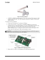
Table 3-11. Typical Battery Life for Various Battery Types
Battery Type
Capacity (mA-hr)
Expected Operation (yrs)
AA
2000
1
C
6000
3
D
12000
6
When a sensor board is added the average current consumption will increase. Designing a low
power sensor interface and control strategy is a key to maintaining battery life. TinyOS is highly
optimized for low power sensor operation but users must be careful both at a hardware and
software level to maintain low power operation. Some of the critical components are:
•
The state of all Mote’s CPU, GPIO and other control lines must be kept in the correct
state during sleep. Setting a single GPIO into the wrong state can add an additional 100
µA of current consumption. Refer to the ATmega128 manual for more specific
information.
•
Many sensors are very low power, and require only a few milliamps of power. Consider
powering them directly from a GPIO line of the processor. This allows the processor to
easily shut down the power during sleep.
•
Be careful of all leakage paths between the battery voltage and ground. A 100K resistor
from the battery to ground will introduce 30 µA or so.
3.5.1
Battery Selection
•
Alkaline Batteries: These are the most common batteries and perhaps the best for
sensors that can operate over the Alkaline’s voltage range. Two AA alkaline batteries will
typically start out at 3.2V but quickly come down to 2.7V. Then the voltage will slowly
degrade over time to around 2.3V before the batteries are depleted. MICA2 and MICAz
units will operate down to this voltage range.
•
Lithium Batteries: These batteries will maintain a voltage at 3.2V or greater and are best
for sensors that require this minimum level of operating voltage.
•
Lithium Thionyl: These batteries are good for applications that require wide temperature
operations (-40 to +80 0C) and have large capacities but are expensive.
•
NiCad: These are rechargeable however have a lower cell voltage (1.2V typically), so
stacking 2 batteries is about 2.4V. When stacking 3 cells the initial voltage can be 4.2V
which is at the maximum operating voltage of the mote. NiCads also have a fairly large
self-discharge rate so are not optimum for infrequent recharge intervals.
•
Temperature range: All batteries are temperature sensitive. Users need to understand
their required operational range and that of the batteries. Alkaline batteries will not work
over an industrial temperature range (-40 °C to +80 °C). Also, at lower temperature ranges
they will have several hundred mV of voltage drop.
Doc.# 7430-0108-01 Rev. D
Page 33
XMesh User’s Manual
3.5.2
Battery Output Impedance
Batteries differ from power supplies regarding output impedance (resistance). Power supplies
have very low output impedance but many batteries exhibit several ohms of resistance under
dynamic conditions. This manifests itself as a voltage drop when the battery current goes from
microamps to milliamps. If the voltage drop is greater than 100’s mV the radio can be affected.
This type of transient behavior is typical of XMesh-LP as the mote wakes up many times each
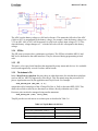
second going from ~15 µA of current draw to over 5-30 mA.
The screen shot in Figure 3-4 shows the behavior of a Lithium Thionyl battery with a 1 Ω output
impedance (due to a fuse) under these transient conditions for a MICA2 running XMesh-LP. The
battery voltage (top trace) was AC coupled to the oscilloscope probe so the average signal is
centered at zero volts. The bottom trace shows when the sensor is turned on and off. After the
sensor turns on the processor sleeps for 300 msec to let the sensor power-on and stabilize.
During the first 80 msec there is a 20 mV drop in the battery voltage due to charging the sensor
circuit. After the 300 msec delay the processor measures the sensor output (using an external
ADC for this unit). Every 125 msec the processor and radio turn on quickly (to measure the
RSSI of the radio signal) and the battery voltage drops almost 75 mV. When the radio transmits
(150msec pulse) the battery voltage drops by 125 mV. This behavior can sometimes be
eliminated by using large capacitors on the battery’s output to supply the required current during
the transmit cycle.
µP sleep
Sensor
measure
µP + radio on to sniff
RF (every 125 msec)
Radio xmit
Charge
Sensor
power on
Sensor
power off
Figure 3-4. Behavior of Lithium Thionyl battery under XMesh-lp
3.6 A Low Power Design Example
This section contains an example of an application optimized for low power using XMesh-ELP.
The sample code is in /MoteWorks/apps/examples/TestElp. The TestElp application is based on
the default XMesh-ELP application /MoteWorks/apps/examples/TestElp2 (refer Section 8.5).
The application requires following:
Page 34
Doc.# 7430-0108-01 Rev. D
XMesh User’s Manual
1. XMesh-ELP (refer to Chapter 8) on a MICAz. The device will act as a ‘leaf node’; i.e. it
will communicate directly with a powered back bone mesh running XMesh-HP.
2. Sample every second, storing the data in SRAM.
3. After twenty samples, transmit the last 20 samples.
Normally XMesh-ELP is used for devices that send data at very low data rates. Periodically,
between data packet transmits, XMesh-ELP would send a health packet and wait for an
acknowledgement. If the acknowledge is not received it will stay awake trying to make contact
with the base station. Transmitting the health packet and waiting for the acknowledgement
consumes more battery current because of the latency time up and down the mesh. If no
acknowledge is received after the time-out it will try again. Health packets typically would be
sent only every several minutes. For this type of application sending a health packet for every
data packet consumes too much energy and does not improve the connectivity to the mesh.
XMesh-ELP allows users to decide when to send data packets and health packets. With this
flexibility a power efficient application can be designed by allowing the application to control
transmission of either packet type. Different Timers used in the application are outlined in Table
3-12.
Table 3-12. Different Timers used in the Application
Timer
Period
(sec)
UpdateTimer 1
WaitTimer
.050
HealthTimer 180
Type
Description
Repeat
Sets sampling interval, fires WaitTimer
One-shot
Sensor power is turned on and a measurement made
Repeat
Fires to signal that a health packet should be transmitted.
When the mote is powered on, it must join the mesh. It does this by calling
ElpI.route_discover():
command result_t StdControl.start() {
call UpdateTimer.start(TIMER_REPEAT, gSampleInterval);
call HealthTimer.start(TIMER_REPEAT, ELP_SLEEP_MS);
call XMeshControl.start();
call ElpControlI.enable();
call ElpI.route_discover(NUM_ROUTE_DISCOVER_INTS);
pressureDataPtr = (pressureMsg * ) call COMM.getBuffer(dataMsgPtr, &Len);
return SUCCESS;
}
During this time the mote will be on all the time (users could modify this to put the mote to sleep
for a period of time, then try again if the ElpI.route_discover_done returns with a fail).
Any data message transmitted during this time will default to the broadcast address (0xffff) and
not be forwarded to the base.
Doc.# 7430-0108-01 Rev. D
Page 35
XMesh User’s Manual
WARNING: When joining the mesh the ELP Mote needs to stay awake for several route
updates (ROUTE_UPDATE_INTERVAL) to join the mesh.
Yes
Once the Mote has joined the mesh the normal data transmissions can start. Before each data
transmission the radio is forced out of the sleep mode. Once XMesh signals that the radio is on
data can be transmitted. After the message is transmitted the code detects if it’s time to send a
health packet. If so the sleep command is restarted with health packets enabled. If not, sleep is
called without issuing health packets. In a typical ELP mode operation, for example the XMeshELP application TestElp2, the health packets are generated automatically even when the ELP
mote is asleep by ensuring that the health_interval is smaller than the sleep interval. In the
default ELP mode the maximum health packet interval is thus constrained by the sleep interval.
The user may control the health packet transmission by disabling the automatic generation of
health packets while the node is asleep. This can be achieved by setting the health interval to be
greater than the sleep interval (refer PressureSensor.h in TestElp application). The users would
now have to create their own health timer to periodically transmit health packets at intervals
greater than the sleep interval. Therefore in the TestElp application, we use a separate
health_timer to initiate periodic health packet transmission.
No
3.7 Estimating the Average Current
The average current can be estimated if the following is known:
•
Current of each operational state
•
Duty cycle of each operational state
For this application, the operational states are:
Page 36
Doc.# 7430-0108-01 Rev. D
XMesh User’s Manual
1. Sleep: The system is in this state approximately 95% of the time.
2. Timer0: This timer service is always running as it supplies timer services for all the
TinyOS components. For the MICAz this timer wakes every 230 msec for 400 µsec,
increments a counter, and goes back to sleep. During this time the processor is using 8
mA of current.
3. Measure Sensor: For this application the sensor is on for 50 msec. The ATmega128 is
used to measure the sensor output (timer counter) so the lowest power state for the
processor is the idle state (4 mA). Also, the sensor itself consumes 400 µA. The
measurements are done every second so the duty cycle is 50 msec/1000 msec.
4. Transmit Data: This occurs every twenty seconds for the application. The data packet is
transmitted in about 4 msec but the MAC layer adds a random back-off of about 4 msec.
Also the link level acknowledgement adds about 2 msec for a total of about 10 msec that
both the radio and processor are awake.
5. Health Data: Health packets are sent only every several minutes. Sending a health
packet is similar to the data packet except that it uses end-to-end acknowledgement. The
time to receive the acknowledgement depends on the message latency up and down the
mesh. Typically for several hops this can be 100 msec to 200 msec. During this time the
processor and radio will be on. If a health packet is sent every 3 minutes and the mote is
on for 300 msec the duty cycle is 0.017%.
Table 3-13. Calculation of Average Current
Operational State
Current (mA)
Duty Cycle (%)
Avg Current (µA)
Sleep
0.015
95
14
Timer0
8
0.17
13
Measure Sensor
4.4
5
220
Transmit Data
30
0.05
15
Transmit Health
30
0.17
50
Total Average Current
312
The screenshot in Figure 3-5 shows the current consumption (vertical axis) of the Mote as a
function of time (horizontal axis). Periodically (every ~230 msec) Timer0 fires to service all
timers. Once every second the mote wakes up and takes sensor data. Once every 20 seconds the
mote also transmits a data packet after taking sensor data.
Doc.# 7430-0108-01 Rev. D
Page 37
XMesh User’s Manual
Measured averaged current
including health packets: 309 µA
50 msec idle to acquire sensor data
Sensor power on
Sensor Measure Interval
Xmit
data
8 mA
Timer Service
Figure 3-5. Current Consumption of a Mote
3.8
Hardware Debugging Techniques
3.8.1
LEDS
The MICA platforms (MICA2/MICAz) have three LEDs (red, yellow and green) that can be
easily used to debug code. TinyOS supplies a component (LedsC) which enables turning any led
off or on; also toggling the led. Inserting calls to the LEDs in the code supplies a visual indicator.
TinyOS also supplies a component, NoLeds, which, if wired to, disables the LEDs (refer to
Appendix D).
3.8.2
JTAG
The ATmega128 processor offers in-circuit debugging through its JTAG interface. This tool
allows users to
•
Perform real time in-circuit debug
•
Trace program execution directly
•
Access CPU registers, RAM, ATmega128 peripherals.
•
Set breakpoints.
•
Change variables and jump over code
In order to use JTAG the following are required:
•
A JTAG pod such as the ones available from Olimex. This device is available with both a
serial port or USB connection:
http://www.olimex.com/dev/avr-jtag.html
Page 38
Doc.# 7430-0108-01 Rev. D
XMesh User’s Manual
Figure 3-6. Olimex JTAG pod
•
A MIB510 or MIB520 programming board. These units contain a JTAG connector which
connects to the JTAG pod. The JTAG connector is labeled as J3 (MOTE JTAG) on the
MIB510/MIB520.
To setup the JTAG environment:
1. Connect the JTAG pod to a PC serial port or USB port.
2. Connect the JTAG pod’s 10 pin header to the MIB510/MIB520. Be careful of the
orientation. There is a silkscreen designator “o” by pin 1 of the MIB510 connector. Also,
there is a square pad (versus the other 9 round pads) on the bottom side of the
MIB510/MIB520 for pin 1. Usually the red wire of the flex cable connecting the JTAG
header to the JTAG pod is pin 1. Make sure the polarity is correct.
WARNING: On the MIB510, DO NOT connect the JTAG pod to the ISP (J8) connector.
This could erase the code in the ISP processor of the MIB510.
Figure 3-7. MIB510 Serial Programming Board
3. Mount a MICA2 or MICAz for debugging on the MIB programming board.
Doc.# 7430-0108-01 Rev. D
Page 39
XMesh User’s Manual
Figure 3-8. MIB510 Attached to Atmel JTAG for Debugging
WARNING: Do not attach a sensorboard that uses the analog-to-digital ADC4-ADC7 pins
as these pins are used for JTAG.
Normally power is supplied to the JTAG via the MIB board’s external power supply. If the pod
is configured to supply power to the mote then do not power the MIB board from the external
power supply.
4. Setup the environment variables for avarice. This can be done in the PC’s environmental
variables/system variables:
Figure 3-9. Setting Environmental and System Variables of the PC
Page 40
Doc.# 7430-0108-01 Rev. D
XMesh User’s Manual
The example shown above sets the JTAG pod for serial port COM1 (S0).
This also can be done from the Cygwin command line:
export AVARICE_ARGS='-j COM1'
To build a debug version of an application do:
make micaz debug or
make mica2 debug or
make iris debug
WARNING: The mote_id address will be 1 and cannot be changed by the normal install
process (since this is not used when loading code via JTAG). A different id can be set in the
StdControl.start routine of the application by coding TOS_LOCAL_ADDRESS = xx (where xx is
the desired id).
Make sure the JTAG fuse is enabled on the mica platform. This can be done using the fuses
script (see Appendix B):
fuses jtagen
WARNING: The default fuse setting is JTAG disabled. Each time the mote is programmed
with make install <platform> the JTAG fuse will be disabled.
Start avr-ice by typing:
ice-insight ./build/mica2/main.exe
ice-insight ./build/micaz/main.exe
ice-insight ./build/iris/main.exe
or ice-gdb (if it doesn’t work). This should download the code image into the Mote via JTAG:
Doc.# 7430-0108-01 Rev. D
Page 41
XMesh User’s Manual
The main screen of the GUI should appear as below. Sometimes this screen is sized incorrectly.
This can be overcome by resizing the window.
step(c)
run
step(assembly)
code modules for the application
Figure 3-10. The Main Screen of the ice-insight GUI
The icons shown will allow:
•
View all source code modules linked into the application
•
Execute (run) the application or run to a breakpoint
•
Step through C code or assembly code.
; NOTE: Stepping through the code is difficult as interrupts are usually enabled and the code
flow will usually branch to an interrupt handler. Setting breakpoints is more efficient.
3.8.3
Setting Breakpoints
Using breakpoint:
•
The “ –“ at the left side of the screen indicates that a breakpoint should be available. Gcc
optimizes the code so not all lines support breakpoint. Even some lines with the “–“
mark will not support a breakpoint.
•
After running the code, if a breakpoint is encountered, the line will be shown highlighted
in green. At this time the code has stopped execution and registers (RAM, etc) can be
examined.
•
The ATmega128 supports up to 4 hardware breakpoints. These breakpoints are internal to
the ATmega128 CPU.
WARNING: Ice-insight does not give any warnings if the breakpoints have been
exceeded. Also, before running ice-insight it’s advisable to cycle the power to reset the hardware
breakpoints since it does not reset them on power-up.
Page 42
Doc.# 7430-0108-01 Rev. D
XMesh User’s Manual
break
Figure 3-11. Debugging using ice-insight GUI
3.8.4
Examining the CPU registers
After the CPU is halted (usually through a breakpoint) the CPU registers can be viewed by
selecting View>Registers.
Users can
•
View all CPU registers including the PC counter (PC), stack pointer (SP) and status
register (SREG).
•
Change the value in any register by entering a new value and hitting return.
•
Restart the program by setting the PC counter to 0x0000, hitting return, and selecting the
run icon (see Figure 3-).
Figure 3-12. Viewing the CPU Registers
3.8.5
Viewing SRAM
SRAM can be viewed by selecting View>Memory. Users can:
•
View and change any section of SRAM
•
View and change any of the CPU I/O registers (see Figure 3-12).
Doc.# 7430-0108-01 Rev. D
Page 43
XMesh User’s Manual
Figure 3-13. Viewing CPU’s I/O Registers
The ATmega128 I/O registers are mapped into a high portion of memory starting at 0x800020.
The Register Summary at the back of the ATmega128 manual shows all registers and their offset
from 0x800020 and 0x800000.
Offset from 0x800020
Offset from 0x800000
$33 ($53)
TCCR0
$32 ($52)
TCNT0
$31 ($51)
OCR0
$30 ($50)
ASSR
FOC0
WGM00
COM01
COM00
WGM01
Timer/Counter0 (8 Bit)
Timer/Counter0 Output Compare Re
–
–
–
–
AS0
Figure 3-14. Viewing CPU Registers (ASSR is at 0x800050)
When viewing the assembly code (see Figure 3-15) the instructions show just the offset from
0x800020.
3.8.6
Viewing Variables
Selecting the View>Watch Expressions allows users to enter the names of variables to monitor.
There are two types of variables to monitor:
1. Global parameters: These are global to the module. To enter these parameters in the
watch window requires entering the name of the module + “$” + name of variable. For
Page 44
Doc.# 7430-0108-01 Rev. D
XMesh User’s Manual
example, to watch gSampleCount in the PressureSensorM module enter
PressureSensorM$gSampleCount in the watch window and Add entry.
2. Local parameters: These are local to the procedure and they are entered directly without
the name of the module.
WARNING: Gcc reuses registers. Be careful when viewing local parameters as the values
in the register may be reused for other instructions.
3.8.7
Viewing Assembly Code
Selecting the SRC+ASM selection on the right side of the screen will display two screens, one
with source code and the other with the assembly code. Users can single step through the
assembly code by using the assembly step button on the screen toolbar.
Figure 3-15. Viewing Assembly Code
3.8.8
SODBUG
SODbug allows users to send sprintf type messages directly from the application code to the
UART serial port. If the Mote is running on a MIB510/MIB520/MIB600 users can send serial
messages directly to any terminal program such as HyperTerminal by configuring 57600 baud, 8
bits, No Parity and 1 Stop Bit.
SODbug code is located in the SODbg.h file in /MoteWorks/tos/interface.
Doc.# 7430-0108-01 Rev. D
Page 45
XMesh User’s Manual
To use SODbug:
•
In the application code insert sprintf-type like:
SODbg(DBG_PKT, “MYAPP$MsgRcvd:%i\n",data);
•
Include SODbug.h and its #defines in all code modules that need serial output
immediately after the start of the implementation section:
implementation {
#define DBG_PKT
#define SO_DEBUG
1
1
#include "SOdebug.h"
An example of SODbug is in /MoteWorks/apps/examples/SODbug
Figure 3-16. Terminal Program showing SODbug
WARNING: SODbug takes over control of UART0. Be careful of conflicts between
SODbug and any UART messaging TinyOS may be doing.
Page 46
Doc.# 7430-0108-01 Rev. D
XMesh User’s Manual
4 XMesh Overview
This section gives a general overview of XMesh and discusses:
•
The different power configurations for XMesh
•
An overview on how XMesh forms an ad-hoc network.
4.1
XMesh Power Configurations
Crossbow sensor networks can run several power strategies. Each strategy is a trade-off between
power and data rates. For systems that have continuous power XMesh-HP is the best solution.
This offers the highest message rate, typically proportional to the baud rate of the radio. For
battery operated systems that require multi-month or multi-year life XMesh-LP and XMesh-ELP
are normally used.
4.1.1
XMesh-HP
In this mode the Mote radios and processors are continually powered. This consumes between 15
to 30 mA depending on the type of Mote. Motes can receive messages and transmit at any time.
Route Update Messages and Health Messages are sent at a faster rate which decreases the time it
takes to form a mesh or for a new mote to join the mesh.
4.1.2
XMesh-LP
The low power mesh can run either time synchronized or asynchronous. The best power
efficiency is achieved with time synchronization supported by XMesh-LP (see Section 7.1.4). In
this mode all motes are time synchronized within ±1 msec. The motes wake-up, typically 8
times/second, time synchronized, for a very short interval to see if the radio is detecting any
signal over the noise background. If so, the radio is kept on to receive the signal. This operation
typically results in a base level current of 80 µA. The total average current depends on the
number of messages received and transmitted. When transmitting data every three minutes the
usual power in a 50 node mesh is around 220 µA. The average current to acquire sensor data will
increase this. XMesh-LP can be configured for even lower power by reducing the wake-up
periods and transmitting at lower rates. Also route update intervals are set at a lower rate to
conserve power. This also results in a longer mesh formation time.
4.1.3
XMesh-ELP
The ELP mode is only used for leaf nodes that communicate with parent nodes running XMeshHP. A leaf node is defined as a node that does not participate in the mesh, it never routes
messages from child motes to parent motes. The ELP version results is very low power because
the mote does not need to use the time synchronized wake-up mode to check for radio messages.
The mote can sleep for very long times. In this mode the mote maintains its neighborhood list to
remember which parents it can select. If it does not get a link level acknowledgement when it
transmits to a parent it will find another parent. This can happen very quickly or may take some
time if the RF environment or mesh configuration has changed considerably.
Doc.# 7430-0108-01 Rev. D
Page 47
XMesh User’s Manual
The Table 4-1 shows the types of power modes supported by Crossbow Motes.
Table 4-1. XMesh Power Configuration Matrix
Power Mode
MICA2
MICA2DOT
MICAz
XMesh-HP
√
√
√
XMesh-LP (asynchronous and time synchronized)
√
√
Asynchronous only
XMesh-ELP
√
√
√
Table 4-2. XMesh Performance Summary Table
Parameter
XMesh-HP
XMesh-LP
XMesh-ELP
Route Update Interval
36 sec.
360 sec.
36 sec if built using HP
360 sec if built using LP
Data Message Rate
10 sec, typ.
180 sec., typ.
Mesh formation time
2-3 times Route Update Interval for mesh with average of 2.5 hops
Average current usage
20-30 mA
<250 µA [1]
< 400 µA
[1]
MICA2-LP using time synchronized mesh.
[2]
MICAz-LP using asynchronous mesh
4.2
N/A
50 µA
[2]
Forming a Multi-hop Mesh Network
To form and maintain a Mesh network, the following 2 parallel processes are involved:
1. Link Estimation
A node promiscuously listens to radio traffic in its neighborhood and uses that
information to populate a neighbor table. It estimates how good it can hear a neighbor by
monitoring the sequence numbers in the Multihop header, and runs an EWMA algorithm
to smooth out that estimate.
The neighbor table size is preset by a #define, usually 16 (see Appendix A). If a mote can
hear more than 16 neighbors it will evict the lowest quality ones from the table. The base
station mote’s neighbor table size is set to a larger value of 40 to handle more neighbors.
Since the base station does not usually run an application it is not as memory constrained
as the children motes.
2. Parent Selection
The node searches its neighbors in the neighbor table and selects the one that will incur
the lowest energy cost to be its parent. A neighbor is considered a parent candidate if it:
Page 48
•
has already joined XMesh
•
is not a descendant node for the last 3 RUIs (Route Update Intervals); this is
intended to avoid cycles
Doc.# 7430-0108-01 Rev. D
XMesh User’s Manual
•
is not an ELP node.
An XMesh multihop network is formed by having all motes in the network periodically broadcast
Route Update Messages, which contains the following information:
1. Parent ID: If the node has not yet joined the mesh, this field is 0xFFFF.
2. Cost: It tells other motes in the neighborhood how much it will cost to send a message
upstream to the base station
3. Hop count: The number of hops to send a message to the base station.
4. A list of qualified neighbors and their quality estimate. Due to the TinyOS packet size,
each route update message will contain at most 5 neighbors. A neighbor is considered
qualified if its receive estimate (defined below) is greater than a threshold (100 for high
power, 10 for low power). By default, the size of neighbor table is 16 for the remote
mote, 40 for the base station, if there are more than 5 qualified neighbors, the node will
sequence through the neighbor list and handle that in multiple, sequential, route update
messages.
The Route Update Message will be broadcasted every RUI (Route Update Interval, defined in
Multihop.h. By default it is set to 36 seconds for high power, and 360 seconds for low power.
The actual number is randomized by multiplying a random number, between 0.9 and 1.1, to the
defined value).
To better understand the processes, we will first define some related metrics:
RE: Receive Estimate, the radio receive quality of the link from a specific neighbor, computed
by applying the EWMA (Exponentially Weighted Moving Average) algorithm to the percentage
of the received packet:
New_Estimate = 255*received / (received + missed)
RE = (1-alpha) * RE + alpha * New_Estimate
Where alpha is the EWMA factor, it is a value between 0 and 1 that defines weight of the new
estimated value.
SE: Send Estimate, the radio transmit quality of the link to a specific neighbor, it is obtained
from the route update messages of the neighbor. When a node broadcasts a route update
message, it also puts its neighbors’ RE in the packet, so neighbors know what the SE is to this
node.
; NOTE: SE and RE are normalized to be a value in [0, 255], with 255 being the perfect
quality.
LC: Link Cost to a specific neighbor. Once SE and RE to a specific node are known, the LC is
computed as:
LC = (1<<18) / (SE * RE)
; NOTE: If the link quality is perfect, which means SE and RE are all 255, the LC is then 4.
This translates to a cost of 4 per hop, provided that the link quality is perfect.
Doc.# 7430-0108-01 Rev. D
Page 49
XMesh User’s Manual
NC: Neighbor’s cost, a value that is obtained from the Route Update Message from a specified
neighbor.
OC: The Cost value of sending message to the base. It is calculated as:
OC = LC + NC
The mote will pick the neighbor with the lowest OC as its parent.
; NOTE: The higher the cost value, the more energy is required to make a transmission to the
base. XMesh then uses the Minimum Transmission (MT) cost metric. The purpose of the cost
metric is to minimize the total cost it takes to transmit to the base station Mote. Each node in the
mesh network will broadcast its cost value. The base station Mote broadcasts a ‘zero’ cost in its
route update messages.
XMesh executes a parent selection task every 8 RUIs, it is assumed that a node needs this
duration to be long enough to gather information about its neighbor and make good decisions
based on the information. XMesh speeds up the Mesh formation time by introducing a fast
formation mode. Once a node enters this mode (for example, the node just boots up, or loses its
old parent etc), it executes the fast formation algorithm and picks a suboptimal parent in order to
join the mesh quickly; it will switch to the best parent later. Since a potential parent has to be
part of the Mesh to be considered as a parent candidate, the time for a node to join the Mesh is a
function of RUI and hop count. As a rule of thumb, the nodes one hop away from the base
station will join the Mesh in 1 RUI, nodes two hops away will join the Mesh in 2 RUI2, so on
and so forth, and it will take 8 RUIs for the Mesh to get stable.
Page 50
Doc.# 7430-0108-01 Rev. D
XMesh User’s Manual
5 Sending and Receiving XMesh Messages
This section discusses how to send and receive messages from an application via the XMesh
network. It includes:
5.1
•
Description of XMesh multihop messages
•
XMesh Messaging API
•
Using the XMesh API
TinyOS Multihop Messages
XMesh messages are TinyOS messages with additional information about the message routing.
Table 5-1. XMesh Message Structure
Component
Description
Header
Composed of standard TOS header and XMesh multihop header
Payload
User data
CRC
CRC check (Refer to Appendix E)
Table 5-2. XMesh Packet Structure
Type
Name
Description
Component
uint16_t
addr
Destination address (next hop)
uint8_t
type
AM type; defines type of message
uint8_t
group
AM group
uint8_t
length
Remaining bytes in message, N/I CRC
uint16_t
sourceaddr
Address of mote that sent the message
uint16_t
originaddr
Address of mote that originated the
message
uint16_t
seqno
Message sequence number.
uint8_t
socket
Application ID
uint8_t
data
Payload
Payload size is set with the
TOSH_DATA_LENGTH define.
Default size is 29 bytes
uint16_t
crc
CRC check (Refer to Appendix E)
CRC
TinyOS Header (MICA2).
The MICAz header has 5
additional bytes.
XMesh multihop header
3 IMPORTANT: The maximum data size is typically limited to 55 bytes. Extending the
data size increases SRAM usage due to creation of multiple TOS buffers.
Shorter data length messages can be sent at any time. TOSH_DATA_LENGTH only determines the
maximum message size (see section 5.2.1).
5.2
XMesh Messaging API
XMesh can transfer messages upstream (from nodes to a base station) and downstream (from a
base station to a node). Downstream communication enables efficient transmission of data from
Doc.# 7430-0108-01 Rev. D
Page 51
XMesh User’s Manual
the base station Mote to a node in the XMesh network. The downstream path is the same as the
upstream path as determined by the upstream route taken by the packets from a node. A
downstream message can only be sent if the base station Mote has previously received an
upstream message from the mote.
3 IMPORTANT: For downstream communication the base station Mote must have
received at least one upstream message from the node (data, health or any other type of upstream
message).
Messages can be sent with two QOS (Quality of Service) levels:
1. Link level acknowledgement: This QOS provides transmission retries between a sender
and receiver mote if an acknowledge message is not received by the sender. This QOS
does not guarantee that a multihop message was successfully transmitted from the
originator to the base station (or downstream). Using link level acknowledgement is the
best QOS for low energy and is appropriate for systems that require the lowest energy
and don’t require 100% delivery of data.
2. End-to-End acknowledgement: This QOS combines link level acknowledges with an
end-to-end acknowledge. For upstream messages the base station will return an
acknowledgement to the originator. For downstream messages the base station will
receive and acknowledge from the intended source. The XMesh API allows the user to
determine if the message should be resent. This QOS consumes more power than just link
level acknowledges and also consumes more of the RF bandwidth. Users can for any
transmission, use either link level or end-to-end acknowledgement (with link level
acknowledgement).
XMesh provides a set of TinyOS data and interfaces that allow users to wire TinyOS components
and call them from their application. Users can do the following:
•
•
•
5.2.1
Send upstream and downstream messages from the end point, with or without requiring
end-to-end acknowledgement
Intercept traffic for in-network processing such as data aggregation and distributed
compression
Snoop traffic for various promiscuous listening purposes
The MhopSend Interface (\MoteWorks\interfaces)
The MHopSend interface uses the application id to parameterize the commands. Users are highly
encouraged to use this interface (as opposed to Send interface which is described below) to
transmit packets. This interface includes the following 3 commands/events:
Example Wiring
MyappM.MhopSend -> XMeshRouter.MhopSend[AP_ID];
Example Usage
call COMM.send(BASE_STATION_ADDRESS, MODE_UPSTREAM,
dataMsgPtr, sizeof(dataMsg));
command void* getBuffer(TOS_MsgPtr msg, uint16_t* length);
Interface
Description Given a TinyOS message buffer, provide a pointer to the data payload section that
an application can use as well as its length. If a protocol-unaware application is
Page 52
Doc.# 7430-0108-01 Rev. D
XMesh User’s Manual
sending a packet with this interface, it must first call getBuffer() to get a
pointer to the valid data region. This allows the application to send a specific
buffer while not requiring knowledge of the packet structure.
Parameter
Description
Msg
The message to get the data region of
Length
Pointer to a field to store the length of the data region.
Return
A pointer to the data region
Interface
command result_t send(uint16_t dest, uint8_t mode,
TOS_MsgPtr pMsg, uint16_t length);
Description Sends a message buffer with a data payload of a specified length
Parameter
Description
dest
Destination Mote_Id for the message.
(Usually BASE_STATION_ADDRESS for upstream messages)
mode
MODE_UPSTREAM_ACK: upstream with return acknowledge,
MODE_UPSTREAM: upstream no return acknowledge,
MODE_DOWNSTREAM_ACK: downstream with return acknowledge
MODE_DOWNSTREAM: downstream no return acknowledge
MODE_ONE_HOP_BROADCAST: one hop broadcast.
pMsg
pointer to the buffer to be sent
length
The length of the data buffer sent using this component. This must be less than or equal to the
maximum length provided by getBuffer()
return
Whether the send request was successful: SUCCESS means a sendDone() event will be signaled
later, FAIL means one will not. This does not mean that the destination mote received the
message, only that the message was transmitted.
command result_t send(TOS_MsgPtr msg, uint16_t length);
Interface
Description This Send interface uses the AM type to parameterize the command. It is provided
to maintain backward-comparability with previous XMesh applications that use
AM type to distinguish different applications. New applications should not use
this interface. Send will send a message buffer with a data payload of a specific
length. The buffer should have its protocol fields set already, either through a
protocol-aware component or by getBuffer().
Parameter
Description
Msg
pointer to the buffer to be sent
length
The length of the data buffer sent using this component. This must be <= the maximum length
provided by getBuffer()
return
whether the send request was successful: SUCCESS means a sendDone() event will be signaled
later, FAIL means one will not. This does not mean that the destination mote received the
message, only that the message was transmitted.
Interface
event result_t sendDone(TOS_MsgPtr msg, result_t success);
Description
Signals when a packet sent with send() completes.
Doc.# 7430-0108-01 Rev. D
Page 53
XMesh User’s Manual
Parameter
Description
Msg
pointer to the message sent
success
Whether the send was successful
SUCCESS: the packet was transmitted and a link level acknowledge received.
th
FAIL: no link level acknowledge was received after 6 transmit attempts. On the 7 attempt a new
th
parent was selected but no acknowledge was received. The 8 attempt was a broadcast message.
return
Should always return SUCCESS
5.2.2
Receive() and ReceiveAck() Interface
This interface allows network end-points to receive a data packet or an acknowledge packet,
without having to know about the internal structure of the packet or the layers below them in the
stack.
Example Wiring
MyappM.RcvAck -> XMeshRouter.ReceiveAck[appID];
Example Usage
event TOS_MsgPtr RcvAck.receive(TOS_MsgPtr pMsg,
void* payload, uint16_t payloadLen)
Interface
event TOS_MsgPtr receive(TOS_MsgPtr msg, void* payload,
uint16_t payloadLen);
event TOS_MsgPtr receiveAck(TOS_MsgPtr msg, void* payload,
uint16_t payloadLen);
Description These two interfaces share the same signature of command/event. The content of
the payload is different.
Parameter
Description
msg
A pointer to the buffer received
payload
The payload portion of the packet for this protocol layer. If this layer has layers above it, it should
signal receive() with payload incremented by the size of its header. Payload is a pointer into the
msg structure.
payloadLen
The length of the payload buffer. If this layer has layers above it, it should signal receive() with
payloadLen decreased by the size of its headers and footers.
return
The buffer to use for the next receive event
Interface
event result_t intercept(TOS_MsgPtr msg, void* payload,
uint16_t payloadLen)
event result_t snoop(TOS_MsgPtr msg, void* payload,
uint16_t payloadLen);
Description intercept(): Signals that a message has been received for the mote and the
wired application ID (AP_ID).
snoop(): Signals any message overheard for the wired application ID (AP_ID).
These two interfaces share the same signature of command/event, the only
difference between the two is that intercept handles the packet that is meant for
the current mote, while snoop handles the packet that is NOT meant for the
Page 54
Doc.# 7430-0108-01 Rev. D
XMesh User’s Manual
current mote. Note that these routines will only intercept/snoop messages for
the application ID that they are wired to.
Parameter
Description
msg
The complete buffer received
payload
The payload portion of the packet for this protocol layer. If this layer has layers above it, it should
signal receive() with payload incremented by the size of its header. Payload is a pointer into the
msg structure.
payloadLen
The length of the payload buffer. If this layer has layers above it, it should signal receive() with
payloadLen decreased by the size of its headers and footers.
success
Indicates the packet should be forwarded, FAIL indicates that it should not be forwarded.
5.2.3
Promiscuous Listening
This interface allows the application to snoop all radio messages including broadcast messages
regardless of the application id and address.
Example Wiring
XMeshRouter.PromiscuousSniff >MyappM.PromiscuousSniff;
Example Usage
event void PromiscuousSniff(TOS_MsgPtr pMsg)
To use PromiscuousSniff include the following declaration in the provides{} section of
the application module.
module XSnfM {
provides {
……
event void PromiscuousSniff(TOS_MsgPtr pMsg);
}
5.3
5.3.1
Using the Messaging API
Active Messaging and Application ID
TinyOS has historically used an AM parameter in TOS messages as a service/application
identifier. This allowed users to route messages to different services in their application. XMesh
now reserves this parameter and it is not available to the user. XMesh supplies the same service
through an Application ID. Application ID is used in the user application as the parameter of
MhopSend interface, while AM type is used inside XMesh (radio layer, routing layer and
transport layer). Application ID allows applications to multiplex to different user services with
the same AM type.
User applications only deal with Application IDs through the MhopSend/receive interface to
send and receive message. XMesh decides which AM type is appropriate for the message. AM
type is internal to XMesh; currently there are 16 predefined AM types in XMesh that users should
never use for other purposes. The most current defined types can be found in Appendix A.
Doc.# 7430-0108-01 Rev. D
Page 55
XMesh User’s Manual
WARNING: Do not use the AM parameter in multihop messages; this parameter is
reserved by XMesh.
3 IMPORTANT: Application IDs from 128 to 255 are reserved by Crossbow for future
use. The user’s Application IDs should always be from 1 to 127.
When sending a message, the application should implement the following code:
1. Get a pointer to a data buffer, and typecast it to an application data structure, for example:
pData = ( Ping_t *) call MhopSend.getBuffer(&gMsgBuffer,&Len));
pData now points to the application payload portion of the TOS message, and Len has
the length of the available payload buffer. The maximum data length is determined by the
TOSH_DATA_LENGTH define.
2. Send the message. The value of dest and mode depends on the transportation mode.
Call MhopSend.send(dest, mode, &gMsgBuffer, length);
Upstream ack
Upstream no ack
Downstream ack
Downstream no ack
dest
Base
Base
Remote mote ID
Remote mote ID
mode
MODE_UPSTREAM_A
CK
MODE_UPSTREAM
MODE_DOWNSTREAM_A
CK
MODE_DOWNSTREM
Base = BASE_STATION_ADDRESS
; NOTE: When calling the MhopSend interface to send packets, XMesh will decide the AM
type for the message based on the mode parameter specified in the function call. The appropriate
AM type will go into the type field of TOS header, and appID will go into the socket field of the
TOSMHop_Msg header.
The base station will respond with an acknowledgement when it receives an upstream message
that requires end-end acknowledgement. It is up to the application to determine whether to
retransmit the message if no acknowledgement has been received.
5.3.2
Sending Upstream Messages
Applications simply call the send command:
call MhopSend.send(BASE_STATION_ADDRESS,MODE_UPSTREAM,&gMsgBuffer, sizeof(bfr));
and implement the sendDone event:
event result_t Send.sendDone(TOS_MsgPtr pMsg, result_t success) {return SUCCESS};
5.3.3
Sending Upstream Messages with End-End Acknowledgements
In order to receive the acknowledgement packet, the application needs to wire in:
AppM.RcvAck -> XMeshRouter.ReceiveAck[appID];
The appID should be the same as in the MhopSend.send wiring. Then the application
implements the ReceiveAck event:
Page 56
Doc.# 7430-0108-01 Rev. D
XMesh User’s Manual
event TOS_MsgPtr RcvAck.receive(TOS_MsgPtr pMsg, void* payload, uint16_t payloadLen) {
// here users can set the state to start sending next packet
}
A common model is to start a one-shot timer after a message is sent out. If the end-end
acknowledgement is not received before the timer expires then the application makes a decision
as to whether to resend the packet. The recommended timer interval is 10 seconds for XMesh-LP
and 20ms for XMesh-HP. A typical example is the following:
In a task (sendTask), send out the packet and start the timer:
if ((call Send.send(BASE_STATION_ADDRESS, MODE_UPSTREAM_ACK,&gMsgBuffer,
sizeof(UpStream_t))) == SUCCESS) {
call TimerAck.start(TIMER_ONE_SHOT, 20); //for high power stack
bAckWait = TRUE;
}
When the timer fired event occurs, decide whether to resend the packet based on a retry number:
event result_t TimerAck.fired() {
if ( NUM_RETRY != num_retry++) {
post sendTask(); }
else { // reach retry limit
num_retry = 0;
bAckWait = FALSE; }
return SUCCESS;
}
If the end-to-end acknowledgement is received before the timer expired, cancel the timer:
event TOS_MsgPtr RcvAck.receive(TOS_MsgPtr pMsg, void* payload, uint16_t payloadLen)
{
if (bAckWait)
{
call TimerAck.stop();
num_retry = 0;
bAckWait = FALSE; }
return pMsg;
}
; NOTE: There is no global sequence number in XMesh (the sequence number in the XMesh
multihop header is on a per hop basis, which is used for link quality computation), so the endend acknowledgement does NOT carry a sequence number of the acknowledged packet. User
applications should not send a new upstream acknowledgement packet if the ack for the previous
packet is not received.
5.3.4
Sending Downstream Messages
There are two scenarios for sending downstream messages:
Doc.# 7430-0108-01 Rev. D
Page 57
XMesh User’s Manual
1. Sending directly from the base station mote.
2. Sending from a PC or other host that is connected to a base station Mote.
If sending from the base station mote, call the following send command:
call MhopSend.send(downstream_node_id, MODE_DOWNSTREAM, &gMsgBuffer, length);
//and implement the sendDone event:
event result_t Send.sendDone(TOS_MsgPtr pMsg, result_t success) { return SUCCESS; }
If downstream packets are sent from a PC or other host via a base station (MIB5xx plus MICA2
or MICAz) running XMeshBase, the PC code needs to:
•
Put the downstream node id to the address field of the TOSMsg header
•
Put 0x0C (downstream no ack) or 0x0E (downstream with ack) into the type field of the
TOSMsg header
•
Put the socket id into the socket field.
•
Compute the crc (appendix E).
•
NEVER modify the multihop header, which is internal to XMesh. XMesh (in the base
station) will complete the remaining fields in the message before sending it downstream.
An example code is like this:
Tos_msg.addr = downstream_id;
Tos_msg.type = 0x0C; // sending downstream no ack
Tos_msg.length = len;
//data length
Tos_msg.socket = application_ID;
//application id to send message to
Memcpy(&tos_msg.data, &app_data, len); //copy data into data section
Tos_msg.crc = crc;
//computed crc, Appendex E
Send_to_serial(&tos_msg); //send the message to the serial port
//this could send the message directly to UART or to a serial forwarder
5.3.5
Sending Downstream Messages with End-End Acknowledgements
If sending from the base station mote, call the following send command:
call MhopSend.send(downstream_node_id, MODE_DOWNSTREAM_ACK, &gMsgBuffer, length);
// and implement the sendDone event:
event result_t Send.sendDone(TOS_MsgPtr pMsg, result_t success) { return SUCCESS; }
If downstream packets are sent from a PC or other host via a base station (MIB5xx plus MICA2
or MICAz) running XMeshBase, the PC is the same as the previous example except for the type
field:
Tos_msg.type = 0x0E; // sending downstream with ack
Page 58
Doc.# 7430-0108-01 Rev. D
XMesh User’s Manual
The PC code should also implement a callback for AM type 247, which is the end-to-end
acknowledgement from the node to base station.
WARNING: Messages to and from XMeshBase require PPP-HDLX framing. Refer to
Chapter 9 for details.
Doc.# 7430-0108-01 Rev. D
Page 59
XMesh User’s Manual
6 XMesh Route Controls
Sometimes users need to make application level decisions based on network conditions. To
accommodate this need, XMesh provides a RouteControl interface (MoteWorks/interfaces)
for the user’s application to extract information from the routing component.
Example Wiring
MyAppM.RouteControl -> XMeshRouter;
Example Usage
parent = call RouteControl.getParent();
Interface
command uint16_t getParent()
Description Returns the address of the present present. (0xffff for broadcast; i.e. no parent)
Interface
command uint16_t getDepth()
Description Returns the node's depth. Depth is defined as how many hops away the mote is
from the base station.
Interface
command uint16_t getSender(TOS_MsgPtr msg)
Description Gets the address of the mote that sent the message.
Parameter
Description
msg
A pointer to the TOS_Msg of interest
return
The address of the sender
Interface
command uint8_t getOccupancy()
Description XMesh queues up forwarding message. Returns the length of the routing
forwarding queue, an indicator of how busy the current node is.
Interface
command uint8_t getQuality(uint8_t type);
Description Gets a measure of goodness for the current parent. Returns value between 0-255
where 255 represents that 100% of messages has been heard.
type=1: sendEst
type=2: receiveEst
Page 60
Doc.# 7430-0108-01 Rev. D
XMesh User’s Manual
Interface
command result_t setUpdateInterval(uint16_t Interval);
Description
Sets the routing components internal route update interval.
Parameter
Description
Interval
The duration, in seconds, of successive routing updates.
return
SUCCESS if the operation succeeded
Doc.# 7430-0108-01 Rev. D
Page 61
XMesh User’s Manual
7 XMesh-LP (Low Power)
This chapter discusses XMesh in the Low Power mode. It will also discuss:
7.1
•
What is Low Power Operation?
•
Low Power Strategies
Low Power Operation
Processor Power Modes
XMesh motes can be configured to listen to radio messages in two modes; High Power (HP) and
Low Power (LP). In High Power, the nodes that make up XMesh network are always on. The
Mote’s microprocessor and radio are continually on and consuming power. The radio is normally
in the receive mode so that the Motes can listen to all neighborhood traffic at any time. This is
the highest bandwidth mode for transmitting packets to the base station Mote.
A processor typically has several modes of operation that consumes different amounts of power.
In the fully active mode, the processor consumes the maximum amount of power, which is
typically in the 8 mA range. In the lowest power consumption mode, some form of deep sleep
mode, the processor only consumes in the order of 15 µAmps.
The differences between the power modes are processor specific. Users should consult Atmel’s
ATmega128 manual for the MICA2, MICAz Motes and ATmega1281 manual for the IRIS
Motes (http://www.atmel.com). Typically the lowest sleep mode will have no peripherals
running and will only provide SRAM retention. Usually an external interrupt is required to wake
the processor. In most applications the external 32 kHz clock is used as the source of the wake
up signal.
In TinyOS, the application user is not actively aware of the power management. There are no
longer any explicit power management calls provided by the OS that will put the processor into
sleep. Instead, since TinyOS is an event driven OS with tasks as the unit of execution, the
scheduler will put the processor to sleep once the task queue is empty.
The processing involved in determining the sleep mode is a series of checks on the activity of the
processor peripherals. The power management module will ensure that the sleep mode set will
be the lowest power mode that can still accommodate the correct operations of currently active
peripherals. The designers of TinyOS decided that since this check will delay the sleep
operation, the actual checks occur before the scheduler calls the sleep command. Thus, it is the
responsibility of low level drivers to call the checks before and after using peripherals. For
further detail consult the scheduler.c and HPLPowerManagement.nc source files.
Radio Power Modes
The radio transceiver typically has two modes of operation. It has a transmit state and a receive
state. Depending on the specific radio transceiver, the TX (Transmit) and RX (Receive)
operations consumes power in the range of 10 to 20 mA. In addition to TX and RX, the radio
transceiver also has a series of low power states. When the transceiver is fully powered down, it
consumes around 3 µW.
Page 62
Doc.# 7430-0108-01 Rev. D
XMesh User’s Manual
7.1.1
Low Power Strategies
Since the OS already takes care of the power management of the processor, the focus then shifts
toward making communication less power intensive. It should be noted that most sensor
network applications have very low data rates that do not require continuous processor or
network activity. Any strategy that tries to reduce energy used by the radio should take
advantage of the low duty cycle requirements of typical sensor network applications. However it
is not enough just to power down the radio when it’s not sending a message. A radio must also
be able to receive messages from its peers and know when to power on the radio for reception.
Power Cycling
Some nodes in a network are known ahead of time to be edge devices that do not need to
participate in routing. These devices can adopt the power strategy of powering on the radio
when they need to communicate and then powering off when the transmission is completed
(XMesh-ELP). This assumes that these edge devices will be able to make contact with a node
that is capable of routing the message from the edge device through the network.
Power Cycling on a Known Schedule
This strategy involves power cycling the radio on a fixed interval by all nodes in a network.
Every node using this strategy will periodically power on their radio to listen for activity. The
listening time of a node is fixed and the interval between each channel monitoring is also fixed.
The period between channel monitoring is known through out the network. Thus if any node
wishes to communicate with its neighbors, it will transmit a wake up sequence for the duration of
the wakeup period before transmitting the actual message. In this fashion if any neighboring
nodes detect any radio activity during its channel monitoring, it will remain on until the message
is completely received. This strategy allows nodes to power down a majority of the time and
only power on during channel monitoring and message transaction.
Power Cycling on a Synchronized Schedule
In the previous strategy, every node in the network powers on their radio at a fixed periodic
interval. If a node monitors the channel 8 times per second then the period is 125 ms between
each channel monitoring. When a node wishes to send, the node must first send a wakeup
sequence of 125 ms or however long this period is. This consumes a lot of energy for simply
notifying its neighboring nodes. The reason the wakeup sequence must span the entire period is
because nodes are not synchronized. Without synchronization nodes do no know the exact
moment in the periodic interval when its neighbors will monitor the channel.
With a synchronized schedule where every node periodically monitors the channel during the
same time window, then the wakeup sequence can be dramatically reduced. This time window,
if in the neighborhood of 1ms, can guarantee that every node will monitor the channel for
activity within 1ms of each other. Thus the wakeup sequence will only need to span 2 ms.
7.1.2
Performance Metrics of Low power techniques
Period Length
The amount of time between two consecutive channel monitoring operations. If a node is
setup to monitor the channel 8 times per second then this length is 125ms.
Doc.# 7430-0108-01 Rev. D
Page 63
XMesh User’s Manual
Bandwidth
Since every node may only send or receive one packet per period, the bandwidth is thus
determined by the length of this period. If the period is 125 ms, then the bandwidth is 8
packets per second.
Latency
The latency is determined by the duration of the listening period. If the duration is 125
ms, then that is the latency per link.
Monitoring Energy
The amount of energy every node must spend to periodically monitor for channel
activity.
Transmission Energy: The amount of energy used for the transmission of every packet
including the wakeup sequence.
Reception Energy: The amount of energy used for the reception of every packet.
7.1.3
Analysis of Low power techniques
Period Length vs. Bandwidth and Latency
The period length is directly proportional to the Latency and inversely proportional to the
bandwidth. Increasing the period length will lower the bandwidth while increasing the
latency
Period Length vs. Energy Consumption
The period length is inversely proportional to the monitoring energy. Thus increasing the
period length will decrease the monitoring energy.
Period Length vs. Transmission and Reception Energy
The period length will only have an effect on transmission and reception energy when the
listening periods are unsynchronized or if a packet need to be send sent out with a
wakeup sequence that must span the entire period length.
The longer the period length is, the greater the wake up sequence must be to span the
entire period length. If the receiver is assumed to be unsynchronized, then on average the
receiver will power on during the middle of the period length. Thus the reception energy
will all increase by only by half as much as the transmission energy on average.
7.1.4
Time Synchronized Radio Stack and the Periodic Wake up Checks
The radio stack uses the synchronized time clock which is provided by the Time Synchronization
service (see Section 7.1.4), to schedule periodic wake-up checks for sensing RSSI. This is
achieved by:
•
A periodic wake-up check is initiated when the clock’s lowest 7 bits all reads zeroed (0)
or 128 ms. A timer event for each wake-up check must be scheduled as well.
•
When a wake-up check needs to be scheduled, the radio stack requests the current time
value. The number of clock ticks are counted until the lower bits read zero (0) and then a
Page 64
Doc.# 7430-0108-01 Rev. D
XMesh User’s Manual
calculation is made for future scheduled wake-up checks. This method allows the clock
value to be moved forward and backward (in time) without causing the undue
interruptions to the timer events.
•
7.1.5
Prior to proper time synchronization, the node relies on the initial un-synchronized value
of the timer, which results in periodic sampling at 128 ms intervals.
Radio Stack and Packet Transmissions
In addition to scheduling the wake-up check, the radio stack also schedules packet transmissions
base on the synchronized clock. There are three types of packet transmissions:
•
Full Extended Preamble
•
Short Extended Preamble
•
Standard Preamble
These various types of packet transmissions are used by the routing and time synchronization
layer based on the recipient list.
The Full Extended Preamble is used to communicate with all neighboring nodes regardless of
the presence of time synchronization. This packet transmission is scheduled to start transmitting
15 ms after the wake-up check so that the nodes that are properly synchronized with the
transmission node incur minimal reception costs.
The Short Extended Preamble is used to communicate with time synchronized nodes. This
packet transmission is scheduled to be transmitted precisely when the other nodes will perform
their channel sampling. Nodes will detect the incoming transmission and have time to turn on
their radios before the actual data packet begins to arrive.
The Standard Preamble is used to communicate with high-power nodes that leave their
receivers on continuously. This packet transmission contains no extra preamble bytes and is
schedule to transmit between the periodic wake-up checks. It can be transmitted without causing
surrounding nodes to wake up.
The Table 7-1 describes the packet transmission type.
Table 7-1 Packet Transmission Types
Packet Type
Usage
Preamble Duration
Start Time
Strength Parameter
Full Extended Preamble
Neighborhood
communication
140 ms
T = 15
0
Short Extended Preamble
Time sync
communication
40 ms
T = 114
0xffff
Standard Preamble
Base station
communication
0 ms (2ms)
T = 15
0x7fff
; NOTE: The network stack uses the different packet transmission types depending on the
value of their strength field in the outgoing packet.
The node’s average power consumption can be calculated by determining the packet
transmission type and the number of packets that were transmitted and received. The expected
Doc.# 7430-0108-01 Rev. D
Page 65
XMesh User’s Manual
lifetime of a node can be calculated by using the parameters for the RX cost, TX cost, and RF
Wake-up check cost as well as the number of each type of packet that was sent and received.
Page 66
Doc.# 7430-0108-01 Rev. D
XMesh User’s Manual
8 XMesh-ELP (Extended Low Power)
This chapter discusses XMesh in the Extended Low Power mode. It will also discuss:
•
What is ELP?
•
XMesh-ELP interface
•
Building XMesh-ELP
•
Testing XMesh-ELP
8.1
What is ELP?
XMesh-ELP achieves the minimum operating power because motes spend almost all of their time
in a sleep state. XMesh-ELP only works for nodes which are located at the edge of the network.
These nodes do not forward radio messages upstream or downstream for other motes; i.e. they
can only be the children of other motes and never the parents. The Figure 8-1 shows a graphical
representation of the network topology.
The XMesh network using High
Power mode for nodes that make
up the backbone and Extended
Low Power mode for nodes
along the edge.
Figure 8-1. XMesh-ELP Network Topology
The ELP strategy is intended for applications were data is send very intermittently. These types
of devices normally sleep for minutes to hours or perhaps days. Some examples of devices that
could use ELP are:
•
Light switches which only send messages several times per day. For this application the
device must quickly wake-up and send the message.
Doc.# 7430-0108-01 Rev. D
Page 67
XMesh User’s Manual
•
Battery operated machines that are only used several times a day. This type of application
could require the machine to power-up and start a communication session for a period of
time then go back to sleep.
ELP Motes join the mesh through the following:
•
On power-up they will stay awake until they join the mesh. This means that they have
located their parents.
•
They can then go into the sleep state. The ELP node retains it’s neighborhood table
during sleep. The next time it wakes up it will use the same parent but if it’s not
successful it will try to use another parent from the table.
•
They will periodically (user-defined) power-up and transmit a health message to the base
station using end-end acknowledge. If they receive an acknowledgement they will go
back to sleep. If no acknowledge is received the ELP node will try several times again
before giving up.
ELP motes transmit route updates but advertise their cost as infinite which means that no other
mote will pick them as a parent. ELP motes assume that the network topology regarding their
parents is static. If the neighborhood experiences drastic changes (eg: all parents are turned-off)
then the ELP mote will start a fast formation process to pick a new parent before it goes back to
sleep. This generally means the ELP node will stay awake for 2-3 route update interval.
8.2 Operational Theory of ELP
On start-up the mote needs to join the mesh. This is done by calling
ElpI.route_discover(rui). The service will wait up to
rui*(ROUTE_UPDATE_INTERVALS) to join the mesh. The event
ElpI.route_discover_done(success, parent) signals the result: if success is TRUE,
then the ELP node has successfully joined the mesh and parent parameter contains the ID of the
parent. If success is FAIL, the node has failed to join the mesh and parent contains broadcast
address. And the user needs to decide whether to try again or sleep.
After the mote has joined the mesh the ElpI.sleep() can be invoked. While the node is in
ELP sleep mode, health packets are periodically (interval specified by the user) sent to the base
station and with an expected acknowledgement from the base station. If the acknowledge does
not return within a set time it will try again, with up to iRetries. After the iRetries, it will
return a sleepdone() with failed and not try again until ElpI.sleep() is called again. If an
acknowledgement is received then the service will stop XMesh, start a timer (health interval) and
put the radio to sleep. After the health interval, the ELP node will wake-up and send another
health packet, waiting for an acknowledgement. It uses the same timeout strategy as previously
described. After the duration time interval has elapsed the sleepDone event will be issued (with
SUCCEED) with the radio powered on.
This service can optionally go into the sleep mode with or without sending the initial health
packet. The parameter force_sleep is used to control this behavior; if it is set to 1, the ELP
node will go to sleep immediately after ElpI.sleep() is called, without sending the initial
probing health packet; if it is set to 0, the ELP node first sends a health packet to the base and
Page 68
Doc.# 7430-0108-01 Rev. D
XMesh User’s Manual
won’t sleep until the acknowledgement is received. Note that in either case the node will send
health packets to the base station periodically and will do iRetries if no acknowledgement is
received.
WARNING: ELP motes can only receive downstream messages if they stay awake which
increases their power consumption. Users can develop a strategy where the ELP Mote wakes,
sends an upstream message requesting messages from the base station.
Figure 8-2. ELP Logic Flow Chart
The Figure 8-3 shows the sequence of events for force_sleep = 0:
SleepDone()
Sleep()
User App
Duration
First Health Packet Sent Immediately
Health Messages
Health Int
Figure 8-3. Sequence of Events during ELP
8.3
The XMesh ELP Interface
There are two interfaces (MoteWorks/tos/interfaces) to control XMesh-ELP enabled Motes.
•
ElpControlI
•
ElpI
Doc.# 7430-0108-01 Rev. D
Page 69
XMesh User’s Manual
8.3.1
ElpControlI Interface
Example Wiring
MyappM.ElpControlI -> XMeshRouter.ElpControll;
Example Usage
call ElpControll.enable();
Interface
command result_t enable()
Description Enables the ELP mode – in this mode the mote will periodically wake and send
health messages to the base as determined by the sleep() command below.
Interface
command result_t disable()
Description Disables the ELP mode
Interface
command bool isActive()
Description Query if the node is in ELP mode
8.3.2
ElpI Interface:
Example Wiring
MyappM.Elpl
Example Usage
Call Elpl.wake();
Interface
-> XMeshRouter.Elpl;
command result_t route_discover(uint8_t rui);
Description Attempts to join the mesh. When called it:
Turns the radio on for up to rui (ROUTE_UPDATE_INTERVALs) attempting
to find a parent.
If a parent is found, sends a health message (retries up to x times) requiring an
end-end acknowledge from the base station.
Parameter
Description
Typical Values
rui
The number of ROUTE_UPDATE_INTERVALS to wait for joining the
mesh (i.e. within this time the mote should have heard 2 route updates
from neighbors and selected a parent)
3
Page 70
Doc.# 7430-0108-01 Rev. D
XMesh User’s Manual
Interface
event result_t route_discover_done(uint8_t success,uint16_t
parent);
Description Event returns after route_discover has either found a parent or timed out
after the rui period. If route_discover fails it’s up to the application to decide
when to try route_discover again.
Parameter
Description
success
SUCCESS: A parent has been found
FAIL: No parent was found
parent
The address of the parent.
Interface
command result_t sleep(uint16_t duration, uint16_t
health_interval,uint8_t iRetries, uint8_t force_sleep);
Description Puts an XMesh-ELP capable mote to sleep.
; NOTE: Also disables UART0 during the sleep time.
Parameter
Description
Typical Values
duration
Sleep duration for the radio(sec). At the end of this interval the
application is signaled (sleep_done) to perform whatever tasks it needs
to do (such as taking data and transmitting the result). NOTE: this only
puts the radio to sleep. The mote can still execute any application
required tasks.
30 minutes
health_
interval
Time between sending health packets (sec). This time determines how
often the mote makes sure that it is still part of the mesh. Increasing the
time interval will reduce power consumption. Health_interval should be
shorter than Duration.
5 minutes
iRetries
Number of times to transmit a health packet and get an
acknowledgement. If the acknowledge fails the sleep_done event will
be returned with success=FAIL and the node will stay awake until the
next call to sleep.
5
force_sle
ep
If force_sleep=zero a health packet is generated immediately after the
command is executed and every health_interval during the duration
interval. If force_sleep=one then health packets are not generated until
after one health_interval.
0
Interface
event result_t sleep_done(result_t success);
Description Event signaled every time the node wakes from the sleep interval.
The radio and UART0 will wake up when the next message is sent or by issuing a
Doc.# 7430-0108-01 Rev. D
Page 71
XMesh User’s Manual
wake() command (see below).
; NOTE: the radio is not on at this time.
Interface
command result_t wake();
Description Wakes a node from sleep into a full power state and turns the radio and UART0
on. When this completes a wake_done() will be signaled.
Interface
event result_t wake_done( result_t success);
Description Signaled after node leaves ELP mode. Always returns SUCCESS.
8.4
Building XMesh-ELP
The application needs to follow the ELP coding requirements for the mote to work properly in
ELP mode. Typical usage of ELP by the user would be:
An external interrupt wakes-up the user’s application. The application calls ElpI.wake()
which turns the radio on and rejoins the mesh.
async event result_t FireDetect.alert( ) {
call ElpI.wake();
// turn on the radio and rejoin the Mesh
}
The application waits until ElpI.wakedone() and then sends radio messages.
event result_t ElpI.wake_done(result_t ss){
call MhopSend.send(…);
}
After the radio message has been sent the application calls ElpI.sleep to return to sleep mode.
; NOTE: ElpI.sleep() returns SUCCESS if the mote has returned to ELP sleep mode.
event result_t Send.sendDone(TOS_MsgPtr pMsg, result_t success) {
call ElpI.sleep(elp_sleep_sec,elp_health_sec,elp_retry,monitor_flag);
return SUCCESS;
}
Page 72
Doc.# 7430-0108-01 Rev. D
XMesh User’s Manual
8.5
Testing XMesh-ELP
A test application for ELP mode is supplied in MoteWorks/apps/examples/TestElp2. This
application will:
•
Start-up in full power.
•
Send route updates and monitor route updates until it joins the mesh.
•
Send a health packet to the base station requesting a downstream acknowledge.
•
Go to sleep for 20 seconds.
•
Repeat the previous two steps continually.
Building the Application:
1. To build the application for a MICAz type
make micaz route,elp
2. Program this into a mote.
3. Build the XMeshBase (Chapter 9) application (route,hp base) and program into the base
station mote.
4. Build and load XSniffer with the same radio frequency.
5. Run the base station on batteries or a MIB programming board.
6. Run XSniffer (refer to Chapter 11).
3 IMPORTANT: The ROUTE_UPDATE_INTERVAL in the Makefile.Component for
both the ELP application and XMeshBase must be the same.
8.6 Monitoring the Network with XSniffer
The following screen shot shows the XSniffer Log page during the startup of the network
1. During the initial phase the ELP Mote has not joined the network. At this time it does not
have a parent as seen by its route update message at 0:07:19. The mote current during this
time is around 26 mA.
2. At 0:07:21 seconds the base station broadcasts a route update (Rte) notifying the ELP
mote that it is seen.
3. At 0:7:52 seconds the ELP mote broadcasts its route update (Rte) and has joined the
network selecting the base station as a parent and it sends health packets.
4. Health packets are sent every 20 seconds.
Doc.# 7430-0108-01 Rev. D
Page 73
XMesh User’s Manual
Figure 8-4. Screenshot displaying XSniffer Output
3 IMPORTANT: If the JTAG fuse (Appendix B) is not disabled the sleep current will be
less than 3 mA.
Page 74
Doc.# 7430-0108-01 Rev. D
XMesh User’s Manual
9 XMeshBase
This chapter discusses XMeshBase which is the standard base station application XMesh. The
topics reviewed are:
9.1
•
What is XMeshBase?
•
XMeshBase services
•
How to build XMeshBase
What is XMeshBase?
All XMesh networks require a base station which acts as a gateway for a PC, Stargate or other
client to interface with the XMesh network. Base stations consist of a MICA2 or MICAz (not a
MICA2DOT) running XMeshBase and mounted on one of the following Crossbow interface
boards:
1. MIB510 using a RS232 serial port interface to the client.
2. MIB520 using a USB port to interface to the client.
3. MIB600 using an Ethernet port to interface to the client.
4. Directly mounted to a Stargate with a serial port interface.
Figure 9-1. Mesh Networking Architecture
Usually the client runs XServe, Crossbow’s server interface to the base station, but users can
directly communicate to the mesh via the base station. The interface between the base station
Mote and the MIB or Stargate is a serial RS232 or TTL interface. It uses a standard serial
protocol for communication.
Doc.# 7430-0108-01 Rev. D
Page 75
XMesh User’s Manual
9.2
XMeshBase Services
XMeshBase provides the following services:
1. It is the seed mote that forms the XMesh network. It outputs route messages that inform
all nearby motes that it is the base station and has zero cost to forward any message.
2. For downstream communication XMeshBase automatically routes messages down the
same path as the upstream communication from a mote.
3. It is compiled with a large number of TinyOS message buffers to handle more children
than other motes in the network.
4. It forwards all messages upstream and downstream from the client using a standard serial
framer protocol.
5. XMeshBase can periodically send a heartbeat message to the client. If it does not get a
response from the client within a predefined time it will assume the communication link
has been lost and reset itself.
9.2.1
Serial Protocol
The base station communicates with the host through a serial bus at a baud rate of 57,600 bps.
The incoming and outgoing packets are framed using a PPP-HDLX protocol
(http://www.faqs.org/rfcs/rfc1662.html). In XMeshBase this is handled by the FramerM TinyOS
component. The format of the packet is:
•
•
•
The raw data packet is wrapped on both ends by a frame synchronization byte of 0x7E.
This is used to detect the start and end of a packet from the stream.
The raw data packet uses an escape byte of 0x7D. This is needed in case a byte of payload
data is the same as a reserved byte code, such as the frame synch byte 0x7E. In such a
case, the payload data will be preceded by the escape byte and the payload data itself will
be exclusively OR’ed with 0x20. For example, a payload data byte of 0x7E would
appear in the data packet as 0x7D 0x5E.
On a Windows XP machine, multiple byte values are byte-swapped in the data stream.
For example, the 2 byte UART Address field (0x007E) will appear as 7E 00 in the byte
stream.
The Table 9-1 describes the raw data packet.
Table 9-1. Raw Data Packet Structure
Sync
0x7E
Type
0x42
Data
TOS_Msg Header
Data
Payload
Byte #
Field
Description
0
Ssynch byte
Always 0x7E
1
Packet Type
Page 76
CRC
0xAFE2
Sync
0x7E
Type
Description
P_PACKET_NO_ACK (0x42)
- User packet with no ACK required.
P_PACKET_ACK (0x41)
– User packet. ACK required. Includes a
prefix byte. Receiver must send a P_ACK
response with prefix byte as contents.
Doc.# 7430-0108-01 Rev. D
XMesh User’s Manual
Byte #
Field
Description
P_ACK (0x40)
– The ACK response to a
P_PACKET_ACK packet. Includes the prefix
byte as its contents.
– An unknown packet type.
P_UNKNOWN (0xFF)
2…n-1
Payload Data
In most cases will be a TinyOS Message of varying
length, which is described below.
n
SYNC_BYTE
Always 0x7E
9.3
Building XMeshBase
XMeshBase is located in the /Moteworks/apps/XMesh/XMeshBase directory.
To build the application run the following command from the application directory:
make <hardware platform> base route,hp for XMesh-HP or XMesh-ELP
make <hardware platform> base route,lp for XMesh-LP
3 IMPORTANT: Before building the application make sure the correct build parameters
are set in the build make files (Chapter 2). If the ROUTE_UPDATE_INTERVAL has been
changed from the default value make sure that XMeshBase and the application are using the
same values in the Makefile.Component.
XMeshBase’s TinyOS message data size must be equal or greater to the application message
size. The default message size for XMeshBase is 55 (see Makefile.component). If the application
data packets are larger than 55 data bytes then build XMeshBase with TOSH_DATA_LENGTH >
55.
As can be seen from the following Cygwin screen XMeshBase will use about 3600 bytes (out of
4096 bytes) of SRAM. This is due to the increased buffers allocated for the base station. Since
no user application runs on the base station this will not be a problem.
To program the compiled code into the mote (MICA2 or MICAz):
make <mote platform> reinstall,0 mib510|mib510|mib600, <device location>
3 IMPORTANT: The base station is always programmed with node ID equal to zero.
Doc.# 7430-0108-01 Rev. D
Page 77
XMesh User’s Manual
9.4
Using the Heartbeat
XMeshBase provides the link from the mesh network to the outside world. It is important that
this link does not fail. To monitor the health of XMeshBase a heartbeat mechanism is
incorporated to validate that the link between the base and the PC is operating correctly. The
heartbeat mechanism sends a heartbeat packet from the base station over the serial port every 5
seconds. Applications running on the PC can monitor the packets to verify that they arrive. If
XMeshBase fails to send a heartbeat the monitoring application can alert users that a problem has
occurred with XMeshBase connection.
For users using XServe with XMeshBase, a complete monitoring solution has already been
incorporated. XServe monitors heartbeats from XMeshBase. If three heartbeats are missed
XServe alerts users of the failure. For applications using the MIB510 or MIB520 programming
board for their base station, XServe will also attempt to restart the XMeshBase application by
power cycling the Mote.
The heartbeat messages sent by the XMeshBase application have the structure described in Table
9-2
Table 9-2. Packet Structure of XMeshBase Heartbeat Messages
Data Fields
Description
uint16_t addr
This the Tos_Msg address field which is always set to 0
uint8_t am_type
This is the Tos_Msg am_type field. The am_type for heartbeat messages are 0xFD
uint8_t group
This is the Tos_Msg group field set to the built group id for XMeshBase
uint8_t length
This is the Tos_Msg length field. The length of the heartbeat message is 2 bytes.
uint16_t seq_no
This is the heartbeat sequence number. It’s a 16 bit number which wraps around
after overflow. The sequence number is useful for applications which want track the
packets though the most important aspect of the heartbeat is its absence.
The heartbeat application is turned on by default in XMeshBase. To remove the heartbeat
functionality from XMeshBase comment out the following line in the Makefile.
CFLAGS += -DFEATURE_HEARTBEAT
To monitor heartbeats start XServe with the following flag:
-heartbeat=<num missed>
The <num missed> variable is the minimum number of heartbeats missed before XServe will
attempt to restart XMeshBase. Each heartbeat period is 5 seconds, so in the case of a serial
connection problem the base station will be down for <num missed>*5 seconds.
Page 78
Doc.# 7430-0108-01 Rev. D
XMesh User’s Manual
10
XMesh Services
The XMesh services include the following features:
•
Health Statistics
•
Time Synchronization for Low Power
•
OTAP
•
WatchDog
10.1 Health Statistics
Health statistic packets allow the user to monitor the health of the XMesh network. They are
enabled or disabled from the user’s application. If enabled they are transmitted upstream to the
base station. These packets contain useful information about how well the Mote is performing in
the mesh regarding radio traffic. Information such as battery voltage and the current parent’s
RSSI is also included.
10.1.1 Enabling Health Packets
XMesh exports a command called health_packet that enables health packet reporting during
run time:
command void
health_packet(bool enable, uint16_t interval);
if enable is TRUE, the health packet will be sent out periodically every interval seconds. Interval
is usually set to several minutes in order not to impact the overall mesh message rate. Typical
values for interval are:
•
XMesh-HP : 1 minute or more
•
XMesh-LP : 10 minutes or more
; EXAMPLE
(also refer to /MoteWorks/apps/examples/XMeshCountsToLeds)
// In the App.nc wiring file add:
AppM.health_packet -> XMeshRouter;
//In AppM.nc, the user can enable the health packet reporting:
// in the AppM.nc uses{ section add:
command void health_packet(bool enable, uint16_t intv);
// in the AppM.StdControl.start section add:
Call health_packet(TRUE, 600);
// 10 minute interval
//This will disable the health packet reporting:
Call health_packet(FALSE,0);
Doc.# 7430-0108-01 Rev. D
Page 79
XMesh User’s Manual
The base station will forward these packets along with other data packets to XServe for data
conversion, and then they can be relayed to MoteView for monitoring. They can also be viewed
with XSniffer (see Chapter 11)
10.1.2 Data Packet – Health Header
There are two types of health packets in XMesh:
•
Statistics Health Packets
•
Neighbor Health Packets
The two health packets are transmitted sequentially (in an alternative fashion, one every health
update interval) and use the same packet format. All health packets use AM type 3 (see
Appendix A)
All Health packets have a similar header component which describes the information contained
within the health packet.
Table 10-1. Statistics Health Packet Structure
Data Fields
Description
uint8_t type_node
This is for backward compatibility. The value of the first 4 bits for
XMesh2 will always be 0xF. Any other value means this is an
XMesh1 health packet.
uint8_t version
Most significant bit: 0 = high power mesh; 1 = low power mesh..
Least 3 significant bits:
0 = XMesh 1 version of health packet.
1 = XMesh 2 version of health packet
uint16_t type
The value of this field indicates if the packet is a statistics packet or a
neighbor packet. Statistic packets have a type of 0x01 and neighbor
packets have a type of 0x02
10.1.3 Data Packet – Statistics Health Packet
Statistical health packets contain statistical information about the packets being sent through the
particular node. The following types of data are sent in this type of packet:
•
Accumulating packet counter (num_node_packets, num_fwd_pkts,
num_drop_pkts, num_rexmits) represent statistical information on packet
transmissions from the node gathered since boot time.
•
Instantaneous power information such current voltage readings and accumulated power
usage in low power.
•
Current parent id and information such as link quality and rssi value.
The statistics health packet fields are provided in Table 10-2.
Table 10-2. Statistics Health Packet Structure
Data Fields
Description
uint16_t seq_num
This is the sequence number of the health packet.
Page 80
Doc.# 7430-0108-01 Rev. D
XMesh User’s Manual
uint16_t num_node_pkts
Number of application packets that have been generated locally.
uint16_t num_fwd_pkts
Number of radio packets that the mote has forwarded in the mesh.
uint16_t num_drop_pkts
Number of radio packets that the mote has dropped due to failed link level
retransmissions.
uint16_t num_rexmits
This is the number of times that the message was re-transmitted.
uint8_t battery_voltage
Battery reading.
uint16_t power_sum
Power statistics in low power radio stack (not used)
uint8_t rsvd_app_type
Reserved Crossbow field to identify sending application.
hn_quality
A record containing information about the link to the present parent
nodeinfo
uint16_t node_id
Parent’s ID
uint8_t link_quality
Link quality to parent
uint8_t path_cost
The routing path cost to the
base station
uint8_t radio_link_indicator
rssi or lqi value of the parent
10.1.4 Data Packet – Neighbor Health Packet
The Neighbor health packet contains information about the Mote’s neighborhood and radio link
quality to these motes. Motes track up to sixteen neighbors. Health packets can only send back
information on five neighbors at any one time. If the table contains more than five neighbors the
information is contained in sequential neighbor packets. If there is only a parent and no other
neighbors the Neighbor health packet is not sent. These are still alternated with the statistics
packets. The diagram below shows the sequence of health packets for a mesh with 10 neighbors
in the neighborhood list.
The format for the neighborhood health packets is provided in Table 10-3.
Table 10-3. Neighbor Health Packet Structure
Data Fields
Description
uint8_t type_node
This field is in the Health header. The bottom 4 bits will contain the
number of neighbors sent in the packet.
hn_quality
nodeinfo
Records containing information about the link quality of the neighbor. Each
record consist of the following elements:
uint16_t
Doc.# 7430-0108-01 Rev. D
Neighbor’s ID
Page 81
XMesh User’s Manual
Data Fields
Description
uint8_t
Link quality normalized to 255 (100%). 100% indicates that
both the neighbor and mote hear 100% of each other’s
messages.
uint8_t
Hop count of the neighbor
uint8_t
The RSSI or LQI value of the neighbor
10.2 Over-the-Air-Programming (OTAP)
The Over-the-Air-Programming (OTAP) feature allows users to reprogram any Mote within the
XMesh network. OTAP allows one or more Motes to receive new programming images from
XServe (via XOtap, a server-side application via wireless communication.
Figure 10-1. XOtap Architecture
10.2.1 How does OTAP Work?
Every Crossbow Mote has an external serial flash memory interfaced to the microprocessor. This
memory can hold up to 512 kB of data and is non-volatile (i.e. retains its contents if no power is
present). OTAP uses this memory to store code. It divides the serial memory into 4 slots (0, 1, 2
& 3) to hold different code/data images. Each slot can be a user-configured number of pages in
2k byte steps. By default each slot is 128 kB (or 64 pages) wide. Unused slots are available to the
user for data logging.
Slot zero always holds the OTAP image. This is the full OTAP loader that must be invoked to
download new code. Users can wire the OTAP components directly into their application
however these components consume several hundred bytes of RAM. Instead Crossbow advises
users to use small component, XOTAPLiteM. This component uses just 30 extra bytes. If an
Application wires in XMesh component, the XOTAPLiteM is automatically available. The server
can send a command to XOTAPLiteM which will then cause the Mote to reboot into the OTAP
image from slot zero to do the full code download. The other slots in the memory are allocated
Page 82
Doc.# 7430-0108-01 Rev. D
XMesh User’s Manual
for user code or data. Before reprogramming, users must ensure that the OTAP image resides in
slot zero of the serial flash memory.
OTAP works by transmitting small code fragments, down to a selected Mote. The entire code
image is broken up into these fragments. As OTAP receives the fragments it will store them in
the serial flash. The downloading sequence is independent of the reprogram and reboot process.
Once code images have been stored in serial flash users can reboot to any image at any time.
Figure 10-2. OTAP image transfer
Reprogramming the microprocessor from serial flash requires that bootloader code resides in the
top part of the ATmega microprocessor’s flash memory. This code is loaded once during the
initial programming of the Mote via UISP.
There are several components required to run OTAP:
•
Bootloader: The piece of code that is guaranteed to execute after each reset of the mote,
independent of the TinyOS application.
•
XOTAPLiteM: A sub-component wired into the user’s application by including XMesh in
the Mote.
•
OTAP code image in slot zero of serial flash.
•
XServe running on the server.
•
XOtap running on the server.
The OTAP functionality is implemented within TinyOS by a component known as XMgmt. This
component is responsible for storing the state of the images in the serial flash, responding to any
queries from the XOtap tool and de-fragmenting program or data images sent from the server.
Doc.# 7430-0108-01 Rev. D
Page 83
XMesh User’s Manual
10.2.2 XOTAPLiteM
The XOtapLoader programmed can be wired into the user’s application as follows: In the
Application component file, add the following wiring:
implementation {
……
……
MyAppM.XOtapLoader -> MULTIHOPROUTER;
}
In the Application module file add the following component interface and the command:
module MyAppM {
provides {
…
…;
}
uses {
…
interface XOtapLoader;
…
}
Also add the command response command to check with the application if it can be interrupted
before rebooting to another image. If the application is in the middle of a state, it can properly
complete its actions and leave the mote in a known state before resetting:
event result_t XOtapLoader.boot_request(uint8_t imgId) {
call XOtapLoader.boot(imgId);
return SUCCESS;
}
Once the mote receives the boot command and the application gives a go-ahead on the reboot, it
will schedule the reboot time based on how far away it is from the base, in other words, the
closer it is to the base, the longer it should delay for the reboot, so that children won’t lose
pending downstream messages due to the reboot of their parents. The Table 10-2 shows the delay
time for the reboot.
Table 10-2. Delay times for reboot
Hop_count
Page 84
Delay (sec)
≥5
2
4
4
3
6
2
8
1
10
Doc.# 7430-0108-01 Rev. D
XMesh User’s Manual
10.2.3 Bootloader
The Bootloader is an independent piece of code that is guaranteed to execute after each reset of
the Mote, independent of the TinyOS Application. It is responsible for loading the program
image into the Processor program flash memory if commanded prior to the reset by the XOtap
tool’s message.
The bootloader binaries for MICAz, MICA2, MICA2DOT and IRIS are maintained in the
following directory:
/MoteConfig/TOSBootLoader/{bl_micaz.sec, bl_mica2.srec, bl_mica2dot.srec, bl_m2110.srec, bl}
The command to program the bootloader is the following (all as one line):
uisp -dprog=mib510 -dserial=/dev/ttyS0 --wr_fuse_h=0xd8 -dpart=ATmega128 -wr_fuse_e=ff --upload if=bl_micaz.srec
You may need to choose appropriately the parameters for serial port, mote programmer and the
pathname to bootloader binary.
WARNING: The UISP will erase the bootloader every time the Mote is programmed so it
must always be reloaded every programming cycle. Also make sure that the correct fuse settings
are used (--wr_fuse_h=0xd8, -wr_fuse_e=ff)
10.2.4 OTAP Protocol
The OTAP protocol reformats a large code image into pages and fragments in order to reduce the
traffic required for the download process. The downloaded image is broken into pages and
fragments that fit in a TinyOS packet. A fragment is the amount of the image that can be
transmitted in a single TOS packet, i.e. 19 bytes (29-byte TOS message with 7 byte XMesh
header and 3 bytes OTAP header). A page is a sequential set of fragments that are managed as an
entity. There can be a maximum of 128 fragments per page.
A program image of 31,568 byes for example would be fragmented as:
1. 31568/19 = 1662 fragments (with round off)
2. 1662 fragments / 128 = 12 pages of 128 fragments and 13th page with 126 fragments.
Doc.# 7430-0108-01 Rev. D
Page 85
XMesh User’s Manual
Send LOAD_IMAGE to all motes
All pages
downloaded
Yes
No
Get next page
Clean up,
generate report,
exit
Send
LOAD_PAGE to
all motes
Yes
All motes
downloaded
No
Throttle Control
Remove mote
from download
list
Send all
outstanding
fragments in page
Error?
No
10.2.5 OTAP Download Packet Format
The OTAP download packet contains the fields described in Table 10-3.
Table 10-3. OTAP Packet Fields
Field
Length (Number of Bytes)
Description
Image Id
1
This is the slot in the serial flash – between 0... 3.
Fragment
2
This is the fragment id of the fragment being transmitted.
data
19
This is the binary data for the fragment.
; NOTE: The OTAP packet does not contain any page information. The page containing a
fragment is determined by dividing the fragment offset by 128 (offset >> 7).
10.2.6 Promiscuous Listening
During an image download, the Motes in the download list will listen “promiscuously” for
download packets and read fragments to update the image in the designated slot, even if the
fragment is addressed to another Mote. When it is their turn to download fragments, the OTAP
Page 86
Doc.# 7430-0108-01 Rev. D
XMesh User’s Manual
algorithm will determine what fragments in the current page have been received and will only
send missing fragments.
Whenever any OTAP download starts, XOtap first informs all the nodes in the list to be
programmed to be ready to receive an “image” in the specified slot. Then it informs all the nodes
in the list that it is going to send a specified page. After that, starting from the first node in the
list, it sends downstream packets of data. All nodes which can hear this packet will
“promiscuously” listen to this packet and update their slot.
10.2.7 XOtap Application
The XOtap application is a server side tool that works, either with XServe or directly connected
to the serial port of the XMesh Gateway, to communicate with the XMesh network. It resides in
the XServe Layer (in a remote or local server or Stargate) of the XMesh Network landscape. You
use XOtap to download program images to the Motes by having the application first read an
IHEX image file name and a list of Motes to download. Then the image is downloaded to each
Mote. The application then writes a report and exits.
There are 3 basic types of OTAP commands:
1. Query - Gets status, loaded and boot images information
2. Load - Load program image or data
3. Boot - Boots into the specified image.
XOtap supports the following arguments described in Table 10-4.
Table 10-4. XOtap Command Arguments
Command Interface
Description
-f <image_file>
Download the file.
-i <image_number>
Image number
-q
Query the Mote status
-v <threshold>
Download if the voltage is above the threshold (default 2.7v)
-p <image_number>
Boot the image number.
-sf <ip:port>
XServe host/port (default to localhost:9001)
-c <COM port>
Serial port if connected directly (eg. -c COM1)
moteID [moteID…]
List the Motes to download or check status.
; EXAMPLE
10.2.8 OTAP Preparation using MoteConfig Utility
Before you can program the Motes in the network over the air, you need to prepare them with
bootloader and OTAP image. You can use MoteConfig GUI utility to accomplish this. Follow
these steps to prepare the Motes for over the air programming.
1. Start the MoteConfig from Start>Programs>Crossbow>MoteConfig
Doc.# 7430-0108-01 Rev. D
Page 87
XMesh User’s Manual
2. From Settings>Interface Board Settings… select appropriate programming interface board
and port
Figure 10-3. Programming Interface Board Settings in MoteConfig
3. OTAP enabled programming using UISP – Click on the Local Program tab and click on
Select. Browse to an XMesh application file (main.exe). Choose appropriate Mote ID, Group
ID, RF Power, RF Channel and make sure that OTAP Enable box is checked. Click on Program.
Figure 10-4. Programming XMTS310CA OTAP-enabled application using MoteConfig
4. Repeat the Step 3 for all the nodes in the network. When the bootloader is installed
successfully, the LEDs count up twice when the node is switched on.
5. Program base station Mote with XMeshBase application, Mote ID = 0 and OTAP Enable
unchecked.
Page 88
Doc.# 7430-0108-01 Rev. D
XMesh User’s Manual
Figure 10-5. Programming XMeshBase application into base station using MoteConfig
10.3 OTAP using MoteConfig Utility
Once all the Motes are prepared for OTAP, you can then program them over the air. The
following steps explain how to use MoteConfig to program the nodes in the network.
1. Connect the base node to the PC interface board and turn on the remote nodes that were
prepared as shown in section 10.2.8.
2. Switch to the Remote Program tab.
3. Click on the Search button to start up XServe and listen for remote nodes. The Motes
found within the network will be displayed in the tree-view control as shown in Figure
10-6.
Doc.# 7430-0108-01 Rev. D
Page 89
XMesh User’s Manual
Figure 10-6. Searching for nodes within the mesh network.
; NOTE: The base node will periodically blink with a magenta background. This indicates
that heartbeat packets sent by the base firmware are being received by the PC. This verifies that
the base station has been correctly configures.
4. The Motes can now be rebooted to the OTAP image (OtapGold.exe) by selecting nodes
from the tree-view control and pressing the Prepare button. Nodes can also be selected
by entering their IDs into the Select Nodes textbox. During this process, the Prepare
button will be disabled and the selected node will turn blue.
; NOTE: The node IDs entered in the Select Nodes textbox override the node selection in the
tree-view control.
When the nodes have rebooted into the OTAP image, their background color will turn gold
as shown in Figure 10-7.
Page 90
Doc.# 7430-0108-01 Rev. D
XMesh User’s Manual
Figure 10-7. Nodes are running the OTAP image
5. Query – Users can optionally query a node when it is running the OTAP Image to get
information about different slots as shown in Figure 10-8.
Figure 10-8. Querying the Nodes in the Network for OTAP Image
Doc.# 7430-0108-01 Rev. D
Page 91
XMesh User’s Manual
6. Program – Click on Select and browse to the binary image of the XMesh application
(main.exe) that you want to program with. Check the nodes you want to program and
specify the slot where you want to store the application. Alternatively, you can type the
node IDs in Select Nodes box. Click on Program as shown in Figure 10-9. As the OTAP
progresses, you will see the report in terms of number of pages downloaded into the
flash. During the OTAP process, the color of the selected nodes turns to Orange as shown
in Figure 10-10.
WARNING: You cannot write over the Slot 0, because it is reserved for the OTAP Image.
Figure 10-9. Select an Application for Programming the Nodes
Page 92
Doc.# 7430-0108-01 Rev. D
XMesh User’s Manual
Figure 10-10. Programming the nodes in the network via XOTAP
Open the Process Messages window (by clicking on File > View Process Details…) to
trace all downloading steps as shown in Figure 10-11. . When all the selected nodes are
successfully programmed, the color of the selected nodes turns back to gold.
Figure 10-11. Trace all downloading steps
7. Reboot – The last step is to reboot into the newly loaded image for the selected nodes. To
do this, check the nodes you want to reboot, specify the Slot and click on Reboot.
Alternatively, you can type the node IDs in Select Nodes box. When all the selected nodes
are successfully rebooted, you will see the output shown in Figure 10-12 and the color of
the selected nodes turns back to Green.
Doc.# 7430-0108-01 Rev. D
Page 93
XMesh User’s Manual
Figure 10-12. Rebooting the Nodes in the Network
The specified nodes should now start running the new application.
10.3.1 OTAP Using Cygwin Interface
For the users who prefer to Cygwin command line interface, the following section describes
step-by-step procedure for the OTAP. The Users can also implement these command line
arguments while developing their own client GUI.
1. Connect the base station to the PC interface board and turn on the remote nodes that were
prepared as per Section 10.2.8.
2. Start XServe on the PC connected to the base station (assuming the base station is
connected to COM3)
$ ./xserve -s=/dev/ttyS3
3. Initialize - The next step in the OTAP process is to reboot all chosen nodes to OTAP
Image for preparation of OTAP’ing a new image.
$ ./xotap.exe -sf localhost -i 0 -p 1 2
Options:
cmd = boot
sf = localhost:9001
group id = 129
debug = 1
Page 94
Doc.# 7430-0108-01 Rev. D
XMesh User’s Manual
html report file = xotap.html
image id = 0
motes = 1 2
Rebooting mote 1 with image 0
Rebooting mote 2 with image 0
2 of 2 motes done
Finished: 2 motes successful, 0 motes failed
4. Query - Users can optionally query a node when it is running the OTAP Image to get
information about different slots.
$ ./xotap.exe -sf localhost -q 1 2
Options:
cmd = query
sf = localhost:9001
group id = 129
debug = 1
html report file = xotap.html
motes = 1 2
Mote 5 (micaz),time since reboot: 2.6 min, voltage: 2.8, boot image: 0
Image
flash[start/stop]
size
checksum
Type
0
0/ 14
28175
fada
bootable
1
64/ 79
28843
1350
bootable
2
****empty***
3
****empty***
Mote 15 (micaz),time since reboot: 2.7 min, voltage: 2.9, boot image: 0
Image
flash[start/stop]
size
checksum
Type
0
0/ 14
28175
5b90
bootable
1
64/ 79
28843
b21a
bootable
2
****empty***
3
****empty***
2 of 2 motes done
Finished: 2 motes successful, 0 motes failed
5. Program - Specify the nodes you want to program and specify the slot. Select the binary
image of the app (main.ihex). As the OTAP progresses, you will see the report in terms
of number of pages downloaded into the flash.
WARNING: You should never write over the Slot 0, because it is reserved for the
OTAP Image.
Doc.# 7430-0108-01 Rev. D
Page 95
XMesh User’s Manual
$ ./xotap.exe -sf localhost -i 2 -f
../../../apps/xmesh/XMTS310/build/micaz/man.ihex 1 2
Options:
cmd = download
sf = localhost:9001
group id = 129
debug = 1
html report file = xotap.html
image id = 2
file = ../../../apps/xmesh/XMTS310/build/micaz/main.ihex
flash offset = 128
bootable = 1
min voltage = 2.7
throttle = 15
motes = 1 2
Mote 1 (micaz),time since reboot: 4.2 min, voltage: 2.8, boot image:
none
Mote 2 (micaz),time since reboot: 4.2 min, voltage: 2.9, boot image:
none
Binary conversion complete, size = 28843 (12 pages, 1519 fragments)
Starting download
Downloading Page 1 of 12
…
…
Page 11, mote 2: 0 fragments, throttle = 15 msec
Page 11 finished
Downloading Page 12 of 12
Page 12, mote 2: 111 fragments, throttle = 15 msec
Page 12, mote 1: 0 fragments, throttle = 15 msec
Page 12, mote 2: 0 fragments, throttle = 15 msec
Page 12 finished
All pages downloaded
Registering image 2 on mote 1
Registering image 2 on mote 2
Download finished
2 of 2 motes done
Finished: 2 motes successful, 0 motes failed
Page 96
Doc.# 7430-0108-01 Rev. D
XMesh User’s Manual
6. Reboot - The last step is to reboot into the newly loaded image for the selected nodes.
When all the selected nodes are successfully rebooted, you will see the output shown
below.
$ ./xotap.exe -sf localhost -i 2 -p 1 2
Options:
cmd = boot
sf = localhost:9001
group id = 129
debug = 1
html report file = xotap.html
image id = 2
motes = 1 2
Rebooting mote 1 with image 2
Rebooting mote 2 with image 2
2 of 2 motes done
Finished: 2 motes successful, 0 motes failed
The specified nodes should now start running the new application.
10.4 Watch Dog
XMesh uses a watchdog component (WDTM.nc) to perform a watchdog reset after it has missed
5 route update messages in a row. To enable this functionality, add the following line in the
Makefile:
DEFINES += -DUSE_WATCHDOG
Once the watchdog functionality is enabled, the mote will reboot itself if it does not hear any
route update message in a period of 5*RUI (Route Update Interval).
WARNING: Enabling the watchdog timer will increase the sleep current by an additional
15uA for the ATmega128.
3 IMPORTANT: Never enable watchdog on an ELP node, otherwise the ELP node will
keep rebooting itself since it will miss most of the Route Update Message from its neighbors.
10.5 Time Synchronization for Low Power
The Time Synchronization service is used to establish a global network time stamp and to
schedule network communication. Time synchronization is implemented on top of the longpreamble (Full Extended Preamble) communication mechanism that allows nodes to efficiently
communicate before the synchronization process is complete. However, once synchronized, all
transmissions are based on the globally time synchronous framework, which provides:
Doc.# 7430-0108-01 Rev. D
Page 97
XMesh User’s Manual
•
An implemented time synchronization protocol that is based on the system clock signal
from the base station Mote and distributed to each node in the network.
•
Periodically, each node will broadcast its version of the current time along with its
Authority Rating.
The Authority Rating is represented as an 8-bit unsigned integer. When a time sync message is
received, a node will do the following:
1. Set its time clock to the value contained in the packet if the authority value is lower than
its current value.
2. Set its authority value to two greater than the authority value of the packet.
3. Every time a node transmits a packet, the node will increment its authority value by one.
4. If the authority value of an incoming packet’s authority value is equal to the node’s
existing value, then the time value is adopted only if the source’s sequence number is less
than the receiving node’s ID.
; NOTE: The zero (0) is the highest possible authority value and is assigned to the base
station.
When a node transmits a time synchronization packet, it first initiates the transmission. The radio
communication stack fires a timing event to the Time Synchronization Layer when the start
symbol transmission begins. The Time Synchronization Layer reads the current clock value and
writes it into the packet as it is transmitted.
Concurrently, the authority value of the packet is set to 350 until the time values of the packet
are inserted into the packet. This is to ensure that data is updated inside the packet before
transmission. If, for some reason, the timing values are not inserted into the bytes containing the
time reading before it is updated, the low authority value will cause other nodes to ignore the
transmission. The time value is transmitted as a 64-bit integer with the least significant unit
representing 1024th of a second (~1 ms).
The time synchronization service causes nodes to synchronize to the time value that reaches
them in the shortest number of hops. In the event that a link is broken and the node must receive
a synchronization message that has traveled with more hops, the node will wait two extra cycles
before accepting the new updated path. This time synchronization method also considers all
equal length paths as equally accurate.
Page 98
Doc.# 7430-0108-01 Rev. D
XMesh User’s Manual
Beacon broadcast to form
an ad-hoc time authority
hierarchy
Base Station Mote
with global time
Figure 10-13. Time Synchronization in LP Network
In addition to resetting the local clock to the new value, the time synchronization method also
calculates the difference between the new value and the existing clock value in order to estimate
the crystal skew. The estimated crystal skew value is used to automatically update the clock in
between receiving synchronization messages. The synchronization update messages are simply
used to confirm that the current clock correction parameters are accurate.
The XMesh Time Synchronization service is available for XMesh networks using the Low Power
(LP) mode. The purpose of the Time Synchronization is to synchronize all the nodes in the
network to the same time. This is accomplished by declaring the time on the base station Mote as
the global time, then synchronizing all the nodes within the XMesh network to the global time.
This time stamp technique achieves a time synchronization of all the nodes in the XMesh
network with ±1 msec error.
10.5.1 Calculating Offset and Skew
It is often not sufficient to just periodically update the time of all nodes in a network. Crystals
used to keep track of time at different nodes are slightly different. Typical accuracy of a mote
clock crystal is around 20 to 30 ppm. That means that for a 32 kHz clock crystal, the time will
drift more that 1 msec apart from the global time in only 30 second after an update. Thus it is
important to also track the rate of the local crystal to the rate of the global time scale.
The ratio of the rate of the global time over the rate of the local time is called the Skew and the
difference between the global time and the local time is called the offset. One common equation
that expresses the local time in terms of the global time is
Ci(t) = ait + bi
where t is the global time, ai is the skew and bi is the offset. By keeping track of the skew, it is
possible to keep desired synchronization with fewer time updates.
Doc.# 7430-0108-01 Rev. D
Page 99
XMesh User’s Manual
To obtain the current global time from the XMesh Time Synchronization service, your
applications must be wired to the TimeSyncService module using the Time interface.
The Time interface provides the following commands:
interface Time {
/**
* get current time. Return it in tos_time_t structure
**/
async command tos_time_t get();
/** get the high 32 bits of current time */
async command uint32_t getHigh32();
/** get the lower 32 bits of current time */
async command uint32_t getLow32();
/** get clock phase offset since last clock tick
* in unit of micro-seconds.
**/
async command uint16_t getUs();
}
Here is the tos_time_t structure:
typedef struct {
uint32_t high32;
uint32_t low32;
}tos_time_t;
; EXAMPLE
Below is a wiring example to the TimeSyncService:
uses {
interface StdControl as TimeStart;
interface Time;
}
…
implementation{
components YourAppM, TimeSyncService;
YourApp.TimeStart -> TimeSyncService;
YourApp.Time -> TimeSyncService;
…
}
Page 100
Doc.# 7430-0108-01 Rev. D
XMesh User’s Manual
Time is represented by the tos_time_t structure. The tos_time_t is a 64-bit integer which
represents the current time as a number of milliseconds. The 64-bit integer is represented as two
32-bit integers for easier access on platforms which do not recognize 64-bit numbers. The high
32 bits are the most significant bits in the 64 bit time and the low32 bits are the least significant
32 bits in the 64-bit time. The structure of the time packet is provided in Table 10-5. Time
Synchronization Packets use AM type 239 and do not use a mutihop header.
Table 10-5. Time Packet Structure
Parameter
Format
Description
source_addr
uint16_t
Source address of time message
phase
uint8_t
The difference between the mote’s local time and the time update from the last
timesync message.
corr
uint8_t
Smoothed out skew correction value
authority
uint8_t
Authority is the mechanism to form a timesync hierarchy. Each node's initial
authority is its local address (with base station being 0). After that, each node only
accepts timesync packets from nodes with a lower authority. Once a time sync
packet is accepted the nodes local authority becomes the authority of its timesync
parent + 2. Every timesync period the nodes authority increments by one. This is
so nodes that lose their timesync parent will eventually be able to attach to another
node since it will be increasing authority every period.
timeH
uint32_t
Most significant 32 bits
timeL
uint32_t
Least significant 32 bits
(lsb = 1000/1024 sec)
Doc.# 7430-0108-01 Rev. D
Page 101
XMesh User’s Manual
11
XSniffer
Crossbow has developed a tool, XSniffer, which allows users to monitor multi-hop
communication over XMesh. This program runs on a PC and uses a MICA2 or MICAz Mote to
monitor the RF packet traffic. There are two applications to support XSniffer:
1. XSniffer TinyOS code: This code can be built for either a MICA2 or MICAz that runs on
a Crossbow MIB510 or MIB520 base station. The source code is located in
/MoteWorks/apps/general/XSniffer.
2. XSniffer GUI which installs and runs on the PC. The executables are installed in
C:\Program Files\Crossbow\Sniffer.
; NOTE: XSniffer is set for a group ID=0 and TOS_LOCAL_ADDRESS = 0xff00 so that it
should never return an acknowledgement for any radio packet meant for another Mote.
11.1 Building and Starting XSniffer
In the /MoteWorks/apps/general directory, build and install the application for the correct
platform. For a MICAz and a MIB510 this would be
make install micaz mib510,/dev/ttyS0
WARNING: XSniffer does not run XMesh, do not use route,hp or route,lp variables when
building. XSniffer uses TOSH_DATA_LENGTH = 64 which should accommodate the largest user
data packets.
Start the XSniffer GUI, select the correct COM port and START. Network messages should start
to appear in the Log tab.
11.2 Using XSniffer
XSniffer can be used to monitor the behavior of the mesh. It will display all radio messages
overhead within its radio range. Users can use XSniffer to:
•
•
•
•
•
Check to see if a mote has joined the mesh. When this happens the health and data
packets will change from a broadcast address to either the base station address or the
address of another parent.
Monitor the packet sequence numbers of individual mote radio packets.
Monitor downstream radio communication from the base station.
Monitor radio message retries.
Monitor route update and time synchronization messages.
WARNING: XSniffer can only hear radio messages within its radio range. Normally the
XSniffer Mote is located near the base station so that it can monitor all upstream and downstream
traffic from the base station. In this position it will only overhear Route Update Messages from
nearby neighbors within one hop.
Page 102
Doc.# 7430-0108-01 Rev. D
XMesh User’s Manual
11.2.1 Options Tab
This page allows users to control XSniffer and set display filters for incoming messages:
Table 11-1. XSniffer Options
Column
Description
Use Filter
Allows users to set filters on incoming messages based on the message
parameters and using AND/OR logic
Packet Types
XMesh: Display incoming packets as XMesh multihop.
General: Display incoming packets as general TOS packets
RSSI Display
Display the RF strength either as an ICON or decimal value
Log File Options
Log incoming messages to a file
Log Numeric Format Option
Log incoming data in selected format
Packet Detection Efficiency
Measures the percent of packets received over the last n seconds.
Time Sync
Computes the time skew of the global time stamp between the selected mote
(usually the base station) and the displayed motes (TimeSync tab)
Special Packets
Allows users to display special packet types in the Log screen by editing the
XSniffer configuration file.
Figure 11-1. XSniffer GUI Options Screen Display
11.2.2 Log Screen
This screen displays all radio traffic allowed by the filter (see options tab).
Doc.# 7430-0108-01 Rev. D
Page 103
XMesh User’s Manual
Table 11-2. XSniffer Log Screen Parameters
Column
Description
Elapsed time
Timestamp of the message,
stamped by the PC
Addr
The destination address of the
message
RF
Type
Bcast
Local broadcast message
Base
Upstream message to base
Others
Id of the receiving mote
Either numerical or icon display of the radio receive strength (RSSI) as measured by
the XSniffer mote radio.
AM message type
Rte
Route Update
Hlth
Health Message
Sync
Global Time Sync
E2EAck
End to End Ack
Grp
Group ID
Len
Length of message
Src
Address of mote that sent the message
Orgn
Address of mote the originated the message
SeqNo
Sequence number of the message. This number is incremented by the Src mote
each time it transmits a new message (for multihop messages only)
Hops
This field contains hop_count for route update message(Rte), it contains application
id for any other message.
AppId
Application ID
Remaining columns
Data content of message
Figure 11-2. XSniffer Log Screen Display
Page 104
Doc.# 7430-0108-01 Rev. D
XMesh User’s Manual
11.2.3 All
Display a summary of all received messages
Table 11-7. XSniffer All Tab Parameters
Column
Description
Id
Id of the sending mote
Gr
The group number
Route Msg#
Number of route update messages detected.
Time
Time since last message heard (sec)
Health Msg#
Number of health messages detected
Time
Time since last message heard (sec)
Data Msg#
Number of data messages detected
Time
Time since last message heard (sec)
TimeSync Mst#
Number of time sync messages detected
Time
Time since last message heard (sec)
Figure 11-7. XSniffer All Screen Display
11.2.4 Route
This tab displays the route messages. Since this is only a local broadcast message (not forwarded
to the base) not all messages will be detected by XSniffer. The tab displays the normal multihop
information.
Table 11-3. XSniffer Route Parameters
Column
Description
Id
Id of the reporting node
Seq#
Sequence number of the message
Hops
How many hops away the node is from the base station
Parent
Parent of the node
Cost
Cost of sending a message to the base station
Entries
Number of neighbors carried in this message
Idx
Id of the neighbor
Estx
send estimate for the neighbor
Msg#
Number of message received from this node
Time
How long ago (in second) the last message was received
Doc.# 7430-0108-01 Rev. D
Page 105
XMesh User’s Manual
Figure 11-3. XSniffer Route Screen Display
11.2.5 Health
This tab displays health messages.
Table 11-4. XSniffer Health Tab Parameters
Column
Description
Id
Address of mote originating the health packet
MSeq#
Sequence number of the health packet. This is not the multihop header sequence
number. Each health packet from a mote has it’s own incrementing sequence
number
Pwr
XMesh power state (LP or HP)
Vers
Version of XMesh application
HSeq#
Sequence number of the health packet
App#
Number of packets generated by the Mote
Fwd#
Number of packets forwarded by the Mote
Drop#
Number of packets dropped by the Mote
ReXmit#
Number of packets re-transmitted by the Mote
Volts
Battery voltage reported by the Mote
RF
The radio strength of the parent as heard by the mote originating the health packet.
Rsvd
Reserved for internal use
Parent
Parent of the node
LQ
Link quality of neighbor (send estimate and receive estimate). A value of 100 means
100% of messages have been heard/received
CostEst
Cost of sending a message to the base station
Msg#
Number of messages overheard by XSniffer since the start of the test
Time
Time since last message was heard (seconds)
Figure 11-4. XSniffer Health Screen Display
Page 106
Doc.# 7430-0108-01 Rev. D
XMesh User’s Manual
11.2.6 Neighbor
The neighborhood display is based on information derived from health packets and gives
information as to the quality of the radio links to nearby neighbors.
Table 11-5. XSniffer Neighborhood Tab Parameters
Column
Description
Id
Address of mote originating the health packet
MSeq#
Sequence number of the health packet. This is not the multihop header sequence
number. Each health packet from a mote has it’s own incrementing sequence
number
Msg#
Number of messages overheard by XSniffer since the start of the test
Time
Time since last message was heard (seconds)
Cnt
Number of neighbors contained in this packet.
nbrID
Neighbor address
LQ
Link quality of neighbor (send estimate and receive estimate). A value of 100 means
100% of messages have been heard/received
Hops
Hop count of neighbor to base station
RF
The radio strength of the parent as heard by the mote originating the health packet.
Figure 11-5. XSniffer Neighbor Screen Display
11.2.7 TimeSync
This tab displays time synchronization messages.
Table 11-6. XSniffer TimeSync Tab Parameters
Column
Description
Id
Id of the sending mote
Phase
Sequence Number of the message, obtained from the Multihop header
Corr
See section 10.4
Authority
See section 10.4
Raw Time
See section 10.4
Elapsed Time
Global time as referred to the base station (see Options Tab)
Skew (msec)
The time difference between the time message and the base station time. This
computation is based on when the PC time stamps the incoming message. Due to
variable time delays in the sniffer and serial port communication this computation is
only roughly accurate (~100 msec).
Msg#
Number of time sync messages detected
Time
How long ago (in second) the last message was received
Doc.# 7430-0108-01 Rev. D
Page 107
XMesh User’s Manual
Figure 11-6. XSniffer TimeSync Screen Display
Page 108
Doc.# 7430-0108-01 Rev. D
XMesh User’s Manual
12
MoteConfig
MoteConfig is a GUI utility for programming Motes. It provides an interface for downloading
pre-compiled TinyOS software applications. A major benefit of MoteConfig is that Mote
platforms can be programmed without having to install the TinyOS programming environment.
1. MoteConfig dialog window can be started from MoteView by clicking on Tools > Program
Mote... or by double-clicking icon on your Desktop. This will bring up a window shown in
Figure 12-1. Click Local Program on tab.
Figure 12-1. Screenshot of MoteConfig GUI Window
2. Click on Settings > Interface Board Settings... and choose the proper MIB gateway and check
that the port settings are correct.
; EXAMPLE 5-1: Left screenshot shows Interface Board Settings for an MIB510 on COM
port 1. Right screenshot shows Interface Board Settings for an MIB600 with IP address 10.1.1.248
and on the same LAN as that of the PC.
Doc.# 7430-0108-01 Rev. D
Page 109
XMesh User’s Manual
3. Right click on the Select... button on the top right which will open up a directory window
(see Figure 12-2 or navigate to another directory which has the pre-compiled Mote
application you wish to install. Select the specific .exe file of the application you want to
download into the Mote.
Figure 12-2. Screenshot for selecting XMesh applications
; NOTE: The XMesh applications distributed with MoteView now require XMeshBase_xxx.exe
programmed with MOTE ID=0 as base station application.
The binary scan feature built into MoteConfig will display the default parameters
programmed into this application.
4. Specify desired MOTE ID, Group ID, RF Power, and RF Channel from the drop down menus.
5. Right-click on the Program button and you will see the resulting output at the bottom of
the screen (see Figure 12-3).
Page 110
Doc.# 7430-0108-01 Rev. D
XMesh User’s Manual
Figure 12-3. Screenshot of MoteConfig which scanned the main.exe executable file.
The MoteConfig displays the following information that was compiled into the application.
Table 12-7. MoteConfig Parameters
Display
Description
Programmable?
Platform
The type of mote.
No
XMesh Type
The XMesh configuration.
No
Packet Size
The TOS message packet size.
No
Payload Size
The payload data size within the packet.
No
App Sensor
Not used.
No
RF Power
The power output of the radio. Displayed a register value and
dBm.
Yes
Radio Band
The radio frequency band.
No
Channel No
The radio channel within the radio band.
Yes
UART0 baud
The baud rate for UART0 on the mote
Yes
Mote Id
The mote address to program into the unit. This address can be
auto-incremented after each unit is programmed.
Yes
Group Id
The group id of the network
Yes
Health Update
The update rate (sec) of health packets
Yes
Route Update
The route update rate (note: all motes must have the same route
update rate)
Yes
MoteConfig also allows users to load an OTAP image into the serial flash memory (see Section
10.2). The Enable Watch Dog checkbox will enable a watchdog timer (see Appendix A).
Doc.# 7430-0108-01 Rev. D
Page 111
XMesh User’s Manual
13 Appendix A: XMesh Constants
The following constants (#defines) in the XMesh code are used to set configuration parameters
that affect the performance of XMesh.
Parameter
Default Value
Description
TOSH_DATA_LENGTH
29
Defines the maximum data for a tos packet. If
changed, make sure that XMeshBase uses equal or
greater value.
BASE_STATION_ADDRESS
0
Mote address of base station. Should never be
changed
ROUTE_UPDATE_INTERVAL
60 sec for HP
600 sec for LP
Time between route update intervals. These values
should not be changed. If changed, make sure that
XMeshBase and the application use the same
values.
HEALTH_UPDATE_INTERVAL
60
Time between health messages (seconds)
ROUTE_TABLE_SIZE
Base: 30
Others: 15
Defines maximum number of neighbors that mote can
track. If a mote is not in this table it will not be selected
as a parent.
DESCENDANT_TABLE_SIZE
Base: 100
Others 50
Defines the maximum number of children for the mote.
Used for downstream communication
MHOP_QUEUE_SIZE
Base: 16
Others: 8
Define the maximum number of multihop messages
the mote can queue up. Once exceeded messages will
be dropped.
USE_WATCHDOG
0
Enables reboot if no route update messages are heard
within a defined interval
FEATURE_HEARTBEAT
0
Enable/disable base station heartbeat
Parameter
Values
Description
BASE_STATION_ADDRESS
0x0
Base station address
TOS_LOCAL_ADDRESS
n/a
Mote address, usually assigned when loading code
(via install.x or reinstall.x or MoteConfig)
TOS_BCAST_ADDR
0xffff
Broadcast address; radio messages addressed to this
address can be received by all motes
TOS_UART_ADDR
0x007e
TOS messages with this address are sent to the uart
port.
Mote Addresses
Platform Defines
(set when building for a specific platform)
Define
Description
TOSH_HARDWARE_MICAZ
Code is built for MICAz
TOSH_HARDWARE_MICA2
Code is built for MICA2
Page 112
Doc.# 7430-0108-01 Rev. D
XMesh User’s Manual
TOSH_HARDWARE_MICAZC
Code is built for IRIS
Application IDs
Parameter
Values
Description
Application ID
1-127
User available
Application ID
128-255
Crossbow reserved
AM Messages Types
User applications only deal with Application ID through using the MhopSend/receive
interface to send/receive message, and XMesh decides which AM type is appropriate for that
message. AM type is internal to XMesh; currently there are 20 predefined AM type in XMesh
that users should never use for other purposes. The most current values can be found in the
message.h file. The following table shows some of the presently used values.
Name of AM Type (#Define)
Value of
AM_Type
Description
AM_HEALTH
3
Reserved for Health packets from the mote
AM_DATA2BASE
11
Upstream data msg from node to base, no end-end
ack
AM_DATA2NODE
12
Downstream data to node
AM_DATAACK2BASE
13
Upstream guaranteed delivery to base
AM_DATAACK2NODE
14
Downstream guaranteed delivery to node
AM_ANY2ANY
15
Any to any
AM_MGMT
90
OTAP status message
AM_BULKXFER
91
OTAP transfer fragment
AM_MGMTRESP
92
OTAP status acknowledgement
AM_TIMESYNC
239
Time Sync packet
AM_PREAMBLE
240
Low power preamble packet
AM_FASTJOIN
241
Fast join
AM_FASTJOINRESP
242
Fast join
AM_DOWNSTREAM_ACK
246
Ack message from base to node
AM_UPSTREAM_ACK
247
Ack message from node to base
AM_PATH_LIGHT_DOWN
248
Light full power path down to node
AM_PATH_LIGHT_UP
249
Light full power path up to base
AM_MULTIHOPMSG
250
Route update message
Doc.# 7430-0108-01 Rev. D
Page 113
XMesh User’s Manual
Name of AM Type (#Define)
Value of
AM_Type
Description
MODE_ONE_HOP_BROADCAST
251
Single-hop service via XMesh
AM_HEARTBEAT
253
Base station heart beat message
WARNING: Do not use the AM parameter in multihop message when sending messages;
this parameter is reserved by XMesh.
Page 114
Doc.# 7430-0108-01 Rev. D
XMesh User’s Manual
14
Appendix B: MICA FUSE SETTINGS
The ATmega128L and ATmega1281 microprocessors used on all MICA Motes have multiple
fuses that control their operation. These CPU’s fuses can be set with UISP when downloading
code to the mote. The UISP allows users to individually set the high and low byte fuse. The
following tables from the ATmega128L and ATmega1281 manuals show these fuse settings.
The following table corresponds to bit settings in the uisp wr_fuse_h setting for
ATmega128L:
Fuse High
Byte
Bit No.
Description
OCDEN
7
Enable OCD
JTAGEN
6
Enable JTAG
0 (programmed, JTAG enabled)
SPIEN
5
Enable Serial Program and Data
Downloading
0 (programmed, SPI prog. enabled)
CKOPT
4
Oscillator options
1 (unprogrammed)
EESAVE
3
EEPROM memory is preserved through
the Chip Erase
1 (unprogrammed, EEPROM not preserved)
BOOTSZ1
2
BOOTSZ0
1
Select Boot Size (see Table 112 for
details)
0 (programmed)
BOOTRST
0
Select Reset Vector
1 (unprogrammed)
Select Boot Size
Default Value
1 (unprogrammed, OCD disabled)
0 (programmed)
The following table corresponds to bit settings in the uisp wr_fuse_h setting for
ATmega1281:
Fuse High
Byte
Bit No.
Description
OCDEN
7
Enable OCD
JTAGEN
6
Enable JTAG
0 (programmed, JTAG enabled)
SPIEN
5
Enable Serial Program and Data
Downloading
0 (programmed, SPI prog. enabled)
WDTON
4
Watchdog Timer always on
1 (unprogrammed)
EESAVE
3
EEPROM memory is preserved through
the Chip Erase
1 (unprogrammed, EEPROM not preserved)
BOOTSZ1
2
BOOTSZ0
1
Select Boot Size (see Table 112 for
details)
0 (programmed)
BOOTRST
0
Select Reset Vector
1 (unprogrammed)
Select Boot Size
Doc.# 7430-0108-01 Rev. D
Default Value
1 (unprogrammed, OCD disabled)
0 (programmed)
Page 115
XMesh User’s Manual
The following table corresponds to bit settings in the uisp wr_fuse_l setting for ATmega128L:
Fuse Low
Byte
Bit No.
BODLEVEL 7
Description
Default Value
Brown out detector trigger level
1 (unprogrammed)
BODEN
6
Brown out detector enable
1 (unprogrammed, BOD disabled)
SUT1
5
Select start-up time
1 (unprogrammed)
SUT0
4
Select start-up time
0 (programmed)
CKSEL3
3
Select Clock source
0 (programmed)
CKSEL2
2
Select Clock source
0 (programmed)
CKSEL1
1
Select Clock source
0 (programmed)
CKSEL0
0
Select Clock source
1 (unprogrammed)
The following table corresponds to bit settings in the uisp wr_fuse_l setting for ATmega1281:
Fuse Low
Byte
Bit No.
Description
Default Value
CKDIV8
7
Divide clock by 8
0 (programmed)
CKOUT
6
Clock output
1 (unprogrammed)
SUT1
5
Select start-up time
1 (unprogrammed)
SUT0
4
Select start-up time
0 (programmed)
CKSEL3
3
Select Clock source
0 (programmed)
CKSEL2
2
Select Clock source
0 (programmed)
CKSEL1
1
Select Clock source
1 (unprogrammed)
CKSEL0
0
Select Clock source
0 (programmed)
The following table corresponds to bit settings in the uisp wr_fuse_e setting for ATmega128L:
Extended
Fuse Byte
Bit No.
Description
Default Value
–
7
–
1
–
6
–
1
–
5
–
1
–
4
–
1
–
3
–
1
–
2
–
1
M103C(1)
1
ATmega103 compatibility mode
0 (programmed)
WDTON(2)
0
Watchdog Timer always on
1 (unprogrammed)
Page 116
Doc.# 7430-0108-01 Rev. D
XMesh User’s Manual
The following table corresponds to bit settings in the uisp wr_fuse_e setting for ATmega1281:
Extended
Fuse Byte
Bit No.
Description
Default Value
–
7
–
1
–
6
–
1
–
5
–
1
–
4
–
1
–
3
–
1
BODLEVWL2(1)
2
Brown-out Detector trigger level
1 (unprogrammed)
BODLEVWL1(1)
1
Brown-out Detector trigger level
1 (unprogrammed)
BODLEVWL0(1)
0
Brown-out Detector trigger level
1 (unprogrammed)
WARNING: The base station mote (mote id = 0) must run with the external clock enabled
otherwise the UART baud rates will not be correct.
Do not run a MICA2DOT as a base station mote. It uses a 4MHz resonator crystal which is not
accurate enough for high speed uart baud rates.
Always program a MICA2DOT using the internal, 8MHz, oscillator.
The fuse settings can be set via a uisp command such as:
uisp -dprog=mib510 -dserial=/dev/ttyS0 --wr_fuse_h=0xd8 -dpart=ATmega128 -wr_fuse_e=ff
There are several fuses that must be set for correct XMesh operation:
The following table shows fuse setting for ATmega128L:
XMesh
configuration
wr_fuse_h
wr_fuse_l
wr_fuse_e
Description
XMesh-LP and
XMesh-ELP
(no OTAP)
0xd9
0xc4
0xff
•
•
•
•
Clock Source: Internal Oscillator
Brown out detect: disabled
JTAG: disabled
BootLoader: disabled
XMesh-LP and
XMesh-ELP
(OTAP)
0xd8
0xc4
0xff
•
•
•
•
Clock Source: Internal Oscillator
Brown out detect: disabled
JTAG: disabled
BootLoader: enabled
XMesh-HP
(OTAP)
0xd8
0xff
0xff
•
•
•
•
Clock Source: Internal oscillator
Brown out detect: disabled
JTAG: disabled
BootLoader: enabled
Base Station
(XMeshBase)
0xd9
0xbf
0xff
•
•
•
•
Clock Source: External oscillator
Brown out detect: enabled
JTAG: disabled
BootLoader: disabled
The following table shows fuse setting for ATmega1281:
Doc.# 7430-0108-01 Rev. D
Page 117
XMesh User’s Manual
XMesh
configuration
wr_fuse_h
wr_fuse_l
wr_fuse_e
Description
XMesh-LP and
XMesh-ELP
(no OTAP)
0xd9
0xc2
0xff
•
•
•
•
Clock Source: Internal Oscillator
Brown out detect: disabled
JTAG: disabled
BootLoader: disabled
XMesh-LP and
XMesh-ELP
(OTAP)
0xd8
0xc2
0xff
•
•
•
•
Clock Source: Internal Oscillator
Brown out detect: disabled
JTAG: disabled
BootLoader: enabled
XMesh-HP
(OTAP)
0xd8
0xff
0xff
•
•
•
•
Clock Source: Internal oscillator
Brown out detect: disabled
JTAG: disabled
BootLoader: enabled
Base Station
(XMeshBase)
0xd9
0xff
0xfd
•
•
•
•
Clock Source: External oscillator
Brown out detect: enabled
JTAG: disabled
BootLoader: disabled
; NOTE: Enabling the JTAG fuse allows users to debug code on the ATmega128 using a
JTAG pod. If this fuse is enabled on motes running XMesh-LP/ELP then the power consumption
will increase.
Using the internal 8MHz oscillator reduces power consumption. The only time the external
oscillator is needed is for the base station Mote.
Setting fuses with the fuses script
The /MoteWorks/tools/bin has a script which allows the fuses to be read and written easily. The
screen shot below shows the options. The fuses script can be invoked from any application
directory by setting an alias in the profile file (see Appendix C).
Page 118
Doc.# 7430-0108-01 Rev. D
XMesh User’s Manual
15
Appendix C: TinyOS Settings and Scripts
When building TinyOS applications for XMesh make sure the environment variables are set
correctly. If the installation was at /opt/MoteWorks, do the following at the Cygwin command
line.
export TOSROOT=/opt/MoteWorks
export TOSDIR=/opt/MoteWorks/tos
export MAKERULES = /opt/MoteWorks/make/Makerules
These environment variables can be checked by entering:
echo $TOSROOT
echo $TOSDIR
ehco $MAKERULES
Note these variables can be automatically set in the opt/etc/profile file by entering:
#set TOS variables
export TOSROOT=/opt/MoteWorks
export TOSDIR=/opt/MoteWorks/tos
export MAKERULES=/opt/MoteWorks/Makerules
Cygwin Profile File
The profile file is executed when Cygwin starts up and is useful for executing scripts that set
paths and other variables. This file is usually contained in MoteWorks Suite/cygwin/etc.
•
To set a path to the fuses script (see previous appendix) from any application directory
alias fuses="/opt/Moteworks/tools/bin/fuses"
•
To set the serial port as COM1
export AVRICE_ARGS="-j /dev/ttyS0"
•
To invoke the avr-ice jtag program for a MICAz:
alias jtagmicaz="ice-insight build/micaz/main.exe"
usr/local/bin File
Scripts can be executed directly if they’re located in MoteWorks Suite/cygwin/usr/local/bin.
Several scripts such as location.sh, fuses, gettos, settos (located in /MoteWorks/tools/bin) can be
copied to the usr/bin file.
TinyOS scripts
location.sh: This script will list all the files compiled into the application. Run this script only
after successfully building an application. For example
Doc.# 7430-0108-01 Rev. D
Page 119
XMesh User’s Manual
location.sh make micaz route,hp
will show an output similar to:
Page 120
Doc.# 7430-0108-01 Rev. D
XMesh User’s Manual
16
Appendix D: TinyOS Components
Some commonly used TinyOS components are provided below.
Component
LedsC
Wiring Example
MyappM.Leds->LedsC.Leds
Usage
call Leds.redOn(); call Leds.redToggle();
call Leds.yellowOn(); call Leds.yellowToggle();
call Leds.greenOn(); call Leds.greenToggle();
Description
Turn on/off/toggle red,yellow,green leds
Component
NoLeds
Wiring Example
MyappM.Leds -> NoLeds;
Usage Example
call Leds.redOn(); call Leds.redToggle();
Description
This component is any easy way to disable leds without changing any code in the application
module. In the wiring file (ex Myapp.nc) do
#ifdef NO_LEDS
MyappM.Leds -> NoLeds;
#else
MyAppM.Leds -> LedsC;
#endif
Component
TimerC
Wiring Example
T
MyappM.Timer -> TimerC.Timer[unique("Timer")]; [1]
T
P
P
Usage Example
call Timer.start(TIMER_REPEAT, 1000);
call Timer.start(TIMER_ONE_SHOT,5000);
Description
Fire a repetitive or one-shot timer. Time is set in milliseconds, uint_32.
Minimum time is 3 msec
Component
COMM
Wiring Example
MyappM.CommControl -> Comm;
MyappM.SendMsg-> Comm.SendMsg[AM_TYPE]
Usage Example
Call SendMsg.send(TOS_UART_ADDR,MSG_LEN,msg_ptr);
Description
Send a message over the uart or radio (do not use this for sending radio messages with XMesh)
Component
HPLPowerManagementM (not a component)
Wiring Example
MyAppM.PowerManagement -> HPLPowerManageM;
MyAppM.Enable -> HPLPowerManageM.Enable;
MyAppM.Disable -> HPLPowerManageM.Disable;
Usage Example
call Enable();
call PowerManagement.adjustPower();
Description
If enabled, the call to adjustPower() will put the mote into a low power state when there are no
more tasks on the task que.
Doc.# 7430-0108-01 Rev. D
Page 121
XMesh User’s Manual
[1]
P
This is a parameterized interface. TinyOS automatically assigns a value to the unique
(“Timer”) value.
P
Page 122
Doc.# 7430-0108-01 Rev. D
XMesh User’s Manual
17
Appendix E: Computing TOS Packet CRC
The following code is used to compute the CRC of a data packet:
public static int calcByte(int crc, int b)
{
crc = crc ^ (int)b << 8;
for (int i = 0; i < 8; i++)
{
if ((crc & 0x8000) == 0x8000)
crc = crc << 1 ^ 0x1021;
else
crc = crc << 1;
}
return crc & 0xffff;
}
public static int calc(byte[] packet, int index, int count)
{
int crc = 0;
int i;
while (count > 0)
{
crc = calcByte(crc, packet[index++]);
count--;
}
return crc;
}
Doc.# 7430-0108-01 Rev. D
Page 123
Crossbow Technology, Inc.
4145 N. First Street
San Jose, CA 95134
Phone: 408.965.3300
Fax: 408.324.4840
Email: [email protected]