1
Imote2.Builder Kit Manual
Revision A, September 2007
PN: 7430-0765-01
© 2007 Crossbow Technology, Inc. All rights reserved.
Information in this document is subject to change without notice.
Crossbow, MoteWorks, IRIS, MICA, TrueMesh and XMesh are trademarks of Crossbow
Technology, Inc. Other product and trade names are trademarks or registered trademarks of their
respective holders
Imote2.Builder Kit Manual
Table of Contents
About This Document.................................................................................................................. iii
1
2
3
4
5
6
7
8
Introduction.............................................................................................................................1
1.1
Imote2.Builder Kit Overview ........................................................................................ 1
1.2
Package contents............................................................................................................ 1
Hardware Overview ...............................................................................................................2
2.1
Imote2 Processor Board................................................................................................. 2
2.2
ITS400 Sensor Board..................................................................................................... 3
Software Installation ..............................................................................................................4
3.1
Supported PC Platforms and Operating Systems........................................................... 4
3.2
USB driver installation .................................................................................................. 4
3.3
Additional Software Requirements................................................................................ 6
Application Quick Start .......................................................................................................12
4.1
Out of the box-demo .................................................................................................... 12
4.2
Run the Imote2.Builder Blink project.......................................................................... 13
4.3
Create your own .NET Micro Framework application ................................................ 15
Guided Tour ..........................................................................................................................20
5.1
Reference Manual ........................................................................................................ 20
5.2
Micro Framework Samples.......................................................................................... 20
Sample Applications .............................................................................................................22
6.1
Blink ............................................................................................................................ 23
6.2
CountSend.................................................................................................................... 23
6.3
CountReceive............................................................................................................... 23
6.4
XSniffer ....................................................................................................................... 23
6.5
XSensorITS400............................................................................................................ 24
6.6
XAccel ......................................................................................................................... 26
6.7
XSensorITS400Sleep................................................................................................... 27
Client Tools and GUI............................................................................................................28
7.1
MotePlot ...................................................................................................................... 28
7.2
XSniffer ....................................................................................................................... 30
7.3
SerialDump .................................................................................................................. 31
7.4
MFDeploy.................................................................................................................... 32
7.5
MotePong..................................................................................................................... 35
Developer API Reference .....................................................................................................36
Doc.# 7430-0765-01 Rev. A
Page i
Imote2.Builder User’s Manual
8.1
Platform ....................................................................................................................... 37
8.2
Radio Driver ................................................................................................................ 38
8.3
Sensors ......................................................................................................................... 40
8.4
Utilities ........................................................................................................................ 43
Page ii
Doc.# 7430-0765-01 Rev. A
Imote2.Builder Kit Manual
About This Document
The following annotations have been used to provide additional information.
; NOTE
Note provides additional information about the topic.
EXAMPLE
Examples are given throughout the manual to help the reader understand the terminology.
IMPORTANT
This symbol defines items that have significant meaning to the user
WARNING
The user should pay particular attention to this symbol. It means there is a chance that physical
harm could happen to either the person or the equipment.
The following paragraph heading formatting is used in this manual:
1 Heading 1
1.1 Heading 2
1.1.1 Heading 3
This document also uses different body text fonts (listed in Table 0-1) to help you distinguish
between names of files, commands to be typed, and output coming from the computer.
Table 0-1. Font types used in this document.
Font Type
Usage
Courier New Normal
Sample code and screen output
Courier New Bold
Commands to be typed by the user
Times New Roman Italic TinyOS files names, directory names
Franklin Medium Condensed
Doc.# 7430-0765-01 Rev. A
Text labels in GUIs
Page iii
Imote2.Builder Kit Manual
1 Introduction
1.1 Imote2.Builder Kit Overview
Imote2.BuilderKit is designed to be a complete development environment for high performance
wireless sensor networking (WSN) applications leveraging the Microsoft .NET Framework.
Code on the “Mote tier” uses the .NET Micro Framework. The Imote2.Builder Kit provides the
tools to simplify development and deployment of highly customized distributed sensory systems.
It also makes it easy to connect to a base station mote, and capture the resultant data and sensor
readings.
1.2 Package contents
The contents of the Imote2.Builder kit include:
•
3 x Pre-programmed IPR2400 Imote2 Processor boards
•
2 x ITS400 Imote2 Sensor Boards
•
2 x IIB2400 Imote2 Battery Boards
•
1 x USB Cable – A Male to Mini Male
•
6 x AAA 1.5V Alkaline Batteries
•
1 x CD containing Imote2.Builder SDK CDROM
•
1 x CD containing Evaluation Copy of Microsoft® Visual Studio 2005
Doc.# 7430-0765-01 Rev. A
Page 1
Imote2.Builder Kit Manual
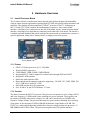
2 Hardware Overview
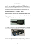
2.1 Imote2 Processor Board
The Crossbow Imote2 is an advanced sensor network node platform designed for demanding
wireless sensor network applications requiring high CPU/DSP and wireless link performance and
reliability. The platform is built around Intel’s XScale® processor, PXA271. It integrates an
802.15.4 radio (TI CC2420) with an on-board antenna. It exposes a “basic sensor board”
interface, consisting of two connectors on one side of the board, and an “advanced sensor board”
interface, consisting of two high density connectors on the other side of the board. The Imote2 is
a modular stackable platform and can be stacked with sensor boards to customize the system to a
specific application, along with a “battery board” to supply power to the system.
Reset Button
USB Connector
2.1.1 Features
•
•
•
•
•
•
•
•
•
PXA271 XScale® processor @ [13–416] MHz
Wireless MMX coprocessor
256kB SRAM, 32MB FLASH, 32MB SDRAM
Integrated 802.15.4 radio, support for external radios through SDIO and UART
Integrated 2.4GHz antenna
Multicolor status indicator LED
Basic and advanced expansion connectors supporting : 3xUART, I2C, 2xSPI, SDIO, I2S,
AC97, USB host, Camera I/F, GPIO
Mini-USB port for direct PC connection
Size: 48 mm x 36 mm. PCB Thickness 1.75 mm
2.1.2 Processor
The Imote2 contains the PXA271 processor. This processor can operate in a low voltage (0.85V)
and a low frequency (13 MHz) mode, hence enabling low power operation. The frequency can
be scaled to 104 MHz at the lowest voltage level, and can be increased up to 416MHz with
Dynamic Voltage Scaling. The processor has many low power modes, including sleep and deep
sleep modes. It also integrates 256 KB of SRAM divided into 4 equal banks of 64 KB. The
PXA271 is a multi-chip module that includes three chips in a single package, the processor, 32
MB SDRAM and 32 MB of flash. The processor integrates many I/O options making it
Page 2
Doc.# 7430-0765-01 Rev. A
Imote2.Builder Kit Manual
extremely flexible in supporting different sensors, A/Ds, radio options, etc. These I/O options
include I2C, 3 Synchronous Serial Ports one of which dedicated to the radio, 3 high speed
UARTs, GPIOs, SDIO, USB client and host, AC97 and I2S audio codec interfaces, fast infrared
port, PWM, Camera Interface and a high speed bus (Mobile Scaleable Link). The processor also
adds many timers and a real time clock. The PXA271 also includes a wireless MMX coprocessor
to accelerate multimedia operations. It adds 30 new media processor instructions, support for
alignment and video operations and compatibility with Intel MMX and SSE integer instructions.
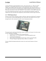
2.2 ITS400 Sensor Board
The basic sensor board is designed to connect to the basic connectors on the Imote2. It contains a
3d Accelerometer, advanced temp/humidity sensor, light sensor and 4 channel A/D. It is a pass
through board to allow stacking with another sensor/communication board.
The sensor board is multi-sensor board that combines a popular set of sensors for wireless sensor
network applications, including:
•
ST Micro LIS3L02DQ 3d 12 bit ±2g accelerometer
•
High Accuracy, ±0.3°C Sensirion SHT15 temperature/humidity sensor
•
TAOS TSL2651Light Sensor
•
Maxim MAX1363 4 Channel General Purpose A/D for quick prototyping
•
TI Tmp175 Digital Temperature Sensor with two-wire interface
For more detailed information about these boards, refer to the Imote2 hardware reference
manual.
Doc.# 7430-0765-01 Rev. A
Page 3
Imote2.Builder Kit Manual
3 Software Installation
3.1
Supported PC Platforms and Operating Systems
The Imote2.builder SDK is supported on the following platforms:
• Windows XP Home
• Window XP Professional
• Windows 2000 with SP4
3.1.1 PC Interface Port Requirements
The Imote2.Builder Kit requires a USB port to provide connectivity to the development device
and gateway.
3.2 USB driver installation
IMPORTANT: Every time you connect an Imote2 to the USB port of your PC, you
should press reset button for the PC to identify your hardware. The reset push button (SW1) is
found just above the mini USB connector.
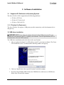
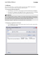
The USB driver installation needs to be done at the very first time.
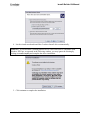
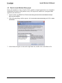
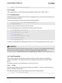
1. After you plug in the Imote2 via USB cable to your PC, press the reset button. The Green
LED would turn on for 2 seconds and the following window will pop up.
2. Check on “Install from a list or specific location” and click on Next>.
3. Insert the Imote2.Builder SDK CD into the CDROM drive and browse to USB Drivers
folder of the CD and click on Next>.
Page 4
Doc.# 7430-0765-01 Rev. A
Imote2.Builder Kit Manual
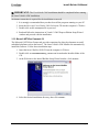
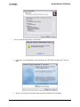
4. Let the wizard search and install the Crossbow Imote2 driver automatically.
; NOTE: If you encounter a warning that the driver is not verified to be compatible with
Windows XP Logo, as appeared in the following window, you may ignore the warning by
clicking on Continue Anyway and complete the driver installation.
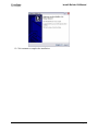
5. Click on Finish to complete the installation.
Doc.# 7430-0765-01 Rev. A
Page 5
Imote2.Builder Kit Manual
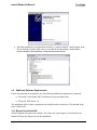
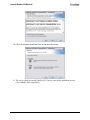
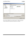
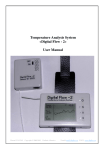
6. After the installation is completed successfully, “Crossbow iMote2” should appear in the
Device Manager window (this can be accessed from Windows Start > Control Panel >
System >Hardware >Device Manager >Universal Serial Bus Controllers).
3.3
Additional Software Requirements
For the development environment to run, the following additional components are required:
• Microsoft Visual Studio 2005 (Evaluation version included in kit)
• Microsoft .NET Micro 2.0
The installation files for these components are included on their respective CDs included in the
Imote2.Builder Kit.
3.3.1 Microsoft Visual Studio 2005
All development using the Imote2.Builder Kit is done in C# and requires Visual Studio to be
installed. Follow the steps below for the installation.
Page 6
Doc.# 7430-0765-01 Rev. A
Imote2.Builder Kit Manual
IMPORTANT: The Visual Studio 2005 installation should be completed before running
the Imote2.Builder SDK installation.
An internet connection is required for the installation to succeed.
1. It is strongly recommended that you shut down all the programs running on your PC.
2. Insert the Microsoft Visual Studio 2005 Evaluation CD into the computer’s CD drive.
3. Double-click on the vcssetup.exe file to proceed.
4. Read and follow the instructions in Visual C# 2005 Express Edition Setup Wizard
window and proceed with the installation.
3.3.2 Microsoft .NET Micro Framework 2.0
The Microsoft .NET Micro Framework provides extensions for doing development on small
embedded platforms such as the Imote2. The Imote2.Builder SDK installer can automatically
install this software. Follow these installation steps.
1. Insert the Imote2.Builder SDK CD into the computer’s CD drive.
2. Double-click on Imote2BuilderSetup_<version>.exe located under Installer folder of the
CD.
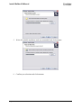
3. At the Welcome to the Imote2.Builder Setup Wizard window, click on Next>.
4. Select the desired installation directory, then click on Next>.
Doc.# 7430-0765-01 Rev. A
Page 7
Imote2.Builder Kit Manual
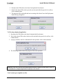
5. Select all available installation tasks (recommended) and click on Next>.
6. Confirm your selections and click on Install.
Page 8
Doc.# 7430-0765-01 Rev. A
Imote2.Builder Kit Manual
7. If you see the message below, click on OK.
8. You will see an installation wizard for Microsoft .NET Micro Framework. Click on
Next>.
9. Be sure to read and accept the license agreement and then click on Next>.
Doc.# 7430-0765-01 Rev. A
Page 9
Imote2.Builder Kit Manual
10. Check the Complete install and click on and Next> then Install.
11. The set-up would also install XSniffer GUI Tool as a part of the installation process.
Click on Next> at the setup dialog.
Page 10
Doc.# 7430-0765-01 Rev. A
Imote2.Builder Kit Manual
12. Click on Finish to complete the installation.
Doc.# 7430-0765-01 Rev. A
Page 11
Imote2.Builder Kit Manual
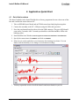
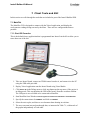
4 Application Quick Start
4.1
Out of the box-demo
The Imote2 modules in the Imote2.Builder kit are factory programmed to run a demo out-of-thebox and visualize the sensor data on a PC.
1. Take an IPR2400 Imote2 board and an ITS400 sensor board and plug them together.
2. Connect the assembly to the PC’s USB port using the USB cable provided.
3. Press the reset button found just above the mini USB connector. The green LED should
come on for 2 seconds. After 5 seconds you should see solid Red and Blue LEDs with
blinking yellow.
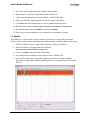
4. Start MotePlot from Windows Start>Programs>Crossbow>Imote2.Builder>Tools>MotePlot
5. Specify the connection to be USBSPOT and click on CONNECT.
6. Select an axis to plot, and observe accelerometer data charting in real-time. You can
shake or tilt the assembly to see change in accelerometer readings.
7. You may repeat this exercise for all the Imote2s and sensor boards in your kit.
Page 12
Doc.# 7430-0765-01 Rev. A
Imote2.Builder Kit Manual
4.2
Run the Imote2.Builder Blink project
During the installation of Imote2.builder SDK, a number of sample applications were included to
demonstrate the features of the platform easily. The steps below outline how to program Blink
application into the Imote2.
1. Open Crossbow.app.Blink from Windows Start>Programs>Crossbow>Imote2.Builder>Sample
App>Crossbow.app.Blink
2. If the following dialog window appears, select Visual C# Development Settings and click on Start
Visual Studio.
3. In the Solution Explorer section on the right hand side, double-click on the Blink.cs file.
Doc.# 7430-0765-01 Rev. A
Page 13
Imote2.Builder Kit Manual
4. Connect an Imote2 board to your PC using the USB cable included in the kit and then press
the reset button. Wait for the green LED to turn off indicating the completion of booting
process.
5. On the right hand side Solution Explorer, double click on the Properties subfolder, and select
the Micro Framework tab. Specify USB from the Transport pull-down menu and verify that
the device name appears.
Page 14
Doc.# 7430-0765-01 Rev. A
Imote2.Builder Kit Manual
6. To start debugging, press the ► play button or press the F5 key. This will compile the
project, upload the code to the Imote2, and begin running the code in debug mode indicated
by “Deploy Succeeded” in Status message bar on the lower right hand side. The Imote2
should begin blinking a blue LED at 1 Hz.
IMPORTANT: When the Visual Studio is in Debug mode, the USB port gets locked and
not available for other applications such as MotePlot. To release the USB port, click on ■ stop
button or select detach from the debug menu.
Upon resetting the Imote2, if the green LED does not switch off in 5 seconds, the Imote2 cannot
be flashed. Check if the Imote2 is connected to any tool and close the tool. Reset the Imote2 and
try again. If the green LED does not turn off in a few moments, reboot your PC.
The current version of .NET Micro Framework does not support more than one Imote2
connecting to PC via USB at the same time, doing so will lead to strange behavior.
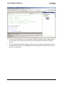
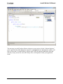
4.3 Create your own .NET Micro Framework application
Visual Studio provides New Project wizard for users to start their projects, the wizard can be
invoked when users select File > New > Project in the VS 2005 menu. The following screenshot
shows the first step to create a .NET Micro Framework application, Micro Framework is selected as
the project type, Console Application is selected as the template. Note that Window Application
template is not supported in the current edition. The users are recommended to select Console
Application template for application project, and Class Library for library project.
Doc.# 7430-0765-01 Rev. A
Page 15
Imote2.Builder Kit Manual
We use the classic “Hello World” as an example in this section. After the user clicks the OK
button, a sub folder HelloWorld will be created in the folder C: \ NETMF \ Projects, and
VS2005 will open the newly created project, as shown in the next screenshot.
Page 16
Doc.# 7430-0765-01 Rev. A
Imote2.Builder Kit Manual
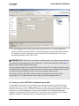
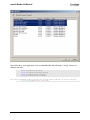
The next step is to add Crossbow library references to your project. On the “Solution Explorer”
panel, right click the folder References, and click on Add Reference, the Add Reference window will
pop up. Select the 4 Crossbow library .dll files under .NET tab and press OK button. Note that
you may or may not need to select all 4 library files, it all depends on what your application
needs.
Doc.# 7430-0765-01 Rev. A
Page 17
Imote2.Builder Kit Manual
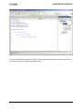
Now add code to your application. It is recommended that the following 4 “using” clauses are
added to the code:
using
using
using
using
Crossbow.lib.utils;
Crossbow.platform.imote2;
Crossbow.radio.cc2420;
Crossbow.sensor.its400;
The next statement simply prints the string “Hello World” to serial output:
SerialDump.print("Hello World");
Page 18
Doc.# 7430-0765-01 Rev. A
Imote2.Builder Kit Manual
Now you can build and deploy the “Hello World” application the Imote2, refer to the procedure
in section 4.2 on how to perform the deployment.
Doc.# 7430-0765-01 Rev. A
Page 19
Imote2.Builder Kit Manual
5 Guided Tour
This section provides a tour of the software and documentation that is included as part of the
Microsoft .NET Micro Framework.
5.1
Reference Manual
The Microsoft .NET Micro Framework includes documentation for the class libraries included.
This documentation can be accessed by going to Windows Start > Programs > Microsoft .NET Micro
Framework > Microsoft .NET Micro Framework 2.0 Documentation
5.2
Micro Framework Samples
The Microsoft .NET Micro Framework includes a few sample applications. These applications
can be accessed by going to Windows Start > Programs > Microsoft .NET Micro Framework > Samples
Page 20
Doc.# 7430-0765-01 Rev. A
Imote2.Builder Kit Manual
; NOTE: TCP/IP socket is not yet supported in .NET MF v2, as such SocketServer and
SocketClient do not run on this Imote2.builder release.
5.2.1 Threading
This sample shows how to use many of the threading features offered by the .NET Micro
Framework, including:
- How to create a thread, start it and wait for it to terminate
- How to create a timer causing a thread pool thread to invoke your method periodically
- How to have a thread wait on an event signaled by another thread
5.2.2 ExtendedWeakReference
This sample shows how to use the Micro Framework’s ExtendedWeakReference class to persist
data across a reboot of the hardware. In particular, this sample records how many times the
hardware has been rebooted and displays the result in the debugger’s Output window.
Doc.# 7430-0765-01 Rev. A
Page 21
Imote2.Builder Kit Manual
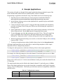
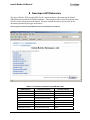
6 Sample Applications
This section will walk you through all the sample applications that are included as part of the
Imote2.builder SDK software that are included on the Crossbow CDROM.
Programming an application into Imote2 using Visual Studio involves the following steps:
1. Open the project or solution that you want to program, located under Windows
Start>Programs>Crossbow>Imote2.Builder> Sample App>Crossbow.app.<app name>
2. In the Solution Explorer section on the right hand side, expand the project and doubleclick on the <app>.cs file.
3. Connect an Imote2 board to your PC using the USB cable included in the kit and then
press the reset button. Wait for the green LED to turn off indicating the completion of
booting process.
4. On the right hand side explorer, double click on the Properties subfolder, and select the
Micro Framework tab. Specify USB from the Transport pull-down menu.
5. To start debugging, press the ► play button or press the F5 key. This will compile the
project, upload the code to the Imote2, and begin running the code in debug mode
indicated by “Deploy Succeeded” in Status message bar on the lower right hand side.
6. When the application downloading is successful, to release the USB port, click on ■ stop
button or Shift + F5 key.
7. To deploy the application un-tethered with the battery board, select Debug>Detach All.
All Sample applications that use the radio follow a similar design template to allow simple
adjustment of basic configuration parameters.
To change the radio parameters, modify the following 2 lines in the sample application.
const ushort _rfChannel = (ushort)RadioChannel.Ch11; // channel 11
const ushort _rfPower = (ushort)RadioPower.M10DBM;
// -10dbm
For example, the following changes use the radio channel 12 and radio power are set to 0 dBm:
const ushort _rfChannel = (ushort)RadioChannel.Ch12;
const ushort _rfPower = (ushort)RadioPower.M0DBM;
Please refer to API section 8.1.5 for the enum definition of radio power and radio channel for the
CC2420 chip.
The sample applications use the default radio channel (channel 11) and radio power (-10dBm).
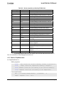
Most of the sample applications use a packet format that is compatible with TinyOS, the packet
carries a 5-byte TosMsg header. This header provides Imote2 protocol compatibility with MICA
and IRIS motes.
Table 6-1. TosMsg Header contents
Page 22
Type
Field Name
Description
uint16_t
Address
Destination address of the packet
uint8_t
AM type
TinyOS Active Message ID
Doc.# 7430-0765-01 Rev. A
Imote2.Builder Kit Manual
uint8_t
Group ID
TinyOS group ID
uint8_t
Length
Length of the packet payload
Please refer to API section 8.4.6.2 on how to set AM type and group ID for TinyOS radio
packets.
6.1
Blink
This application will simply blink a blue colored LED once every second. This application is
used as the example in section 4.2 earlier in this manual. The Blink application is a good test for
the timer subsystem of the platform.
6.1.1 Blink Light Pattern
Light Pattern: Blue (blinking once per second)
6.2
CountSend
The CountSend application provides a basic example for using the radio subsystem of the
platform. This application periodically increments a counter that starts at zero when the node is
booted, and increments by one every second. The count field is both displayed on the LED as a
rotating color representing the lower 3 bits, and sent over the radio in a packet that contains the
full count field in 16 bit resolution. Any nodes running CountReceive within radio range of this
sender will synchronize to the sending node, and display the count.
6.2.1 Count Light Pattern
Light Pattern: Sequentially counts through all 8 colors, switching once per second.
6.2.2 Count Packet Format
Table 6-2. Payload contents of a Count message header
6.3
Type
Field Name
Description
uint16_t
Count
Incrementing count field
CountReceive
The CountReceive application is the sibling application to CountSend. This application turns on
the radio and puts it into receive mode, and waits until it hears a properly formed Count packet.
Once such a packet is received, the node will display the lower 3-bits on the LED just like the
CountSend application. This application can be used to perform simple range tests. The radio
range can be determined by walking the CountReceive node farther and farther away from the
CountSend node until the CountReceive node just stops tracking the count on its LED.
6.4
XSniffer
This firmware will promiscuously listen for radio packets, and forward them via USBSPOT
protocol to the USB port. The XSniffer can also be used as a base station application for singlehop applications such as XSensorITS400, XSensorITS400Sleep and XAccel.
Doc.# 7430-0765-01 Rev. A
Page 23
Imote2.Builder Kit Manual
6.4.1 XSniffer Light Pattern
Light Pattern: Blue (solid -- flashing Yellow whenever packet is overheard)
6.4.2 Compatible PC Tools
The XSniffer app can be used with XSniffer GUI to view data.
6.5
XSensorITS400
This application will periodically send a packet filled with one sample from each sensor on the
ITS400 board. The packet includes the following sensor readings: temperature, light,
accelerometer (X, Y, and Z axis), ADC (all four channels). The default data rate is once every 5
seconds. This application serves as a good example for how to link in the various sensor drivers
and initiate sampling in the .NET Micro framework environment.
The application also offers an alert mode, in which an alert will print out if the temperature
exceeds a certain threshold.
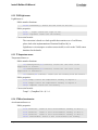
The temperature threshold is set as 40 degree C, as shown below.
#if ALERT_ENABLED
const float _threshold = 40;
float temp;
#endif
To enable the alert functionality, simply uncomment the following line of code in the file
XSensorITS400.cs:
* $Id: XSensorITS400.cs,v 1.18 2007/09/19 21:50:56 nxu Exp $
*/
//To enable the alert, uncomment the following line
//#define ALERT_ENABLED
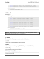
As an alternative, you can also go into project property/build/General section and type
ALERT_ENABLE in the textbox next to “Conditional compilation symbols”.
Page 24
Doc.# 7430-0765-01 Rev. A
Imote2.Builder Kit Manual
6.5.1 XSensorITS400 Light Pattern
Light Pattern: Green (blinking once per second)
6.5.2 XSensorITS400 Packet Format
Table 6-3. Header contents of an XSensorITS400 message header
Type
Field Name
Description
uint8_t
board_id
XSensor packet type field
(XSensorITS400 is always a constant value of 0x20)
uint8_t
packet_id
XSensor packet sub-type field
(XSensorITS400 is always a constant value of 0x01)
uint16_t
node_id
Network short address of sending node.
Table 6-4. Payload contents of an XSensorITS400 message
Type
Field Name
Description
uint16_t
count
Incrementing sequence number for yield calculation
uint16_t
accel_x
Accelerometer reading of X axis
uint16_t
accel_y
Accelerometer reading of Y axis
uint16_t
accel_z
Accelerometer reading of Z axis
uint16_t
temperature
Temperature reading
Doc.# 7430-0765-01 Rev. A
Page 25
Imote2.Builder Kit Manual
uint16_t
temperature2
Temperature reading from Sensirion sensor
uint16_t
humidity
Humidity reading from Sensirion sensor
uint16_t
light
Light reading from Taos sensor
uint16_t
adc1
ADC reading from channel 1
uint16_t
adc2
ADC reading from channel 2
uint16_t
adc3
ADC reading from channel 3
6.5.3 Compatible PC Tools
The XSensorITS400 can be used with SerialDump console to view raw data packets.
6.6
XAccel
This firmware performs high frequency sampling on the 3-axis accelerometer and streams the
data back to the XSniffer or MotePlot PC tools either via radio to a base station, or directly over
a USB connection.
6.6.1 XAccel Light Pattern
Light Pattern: Purple (blinking Yellow twice per second)
6.6.2 XAccel Packet Format
Table 6-5. Header contents of an XAccel message header
Type
Field Name
Description
uint8_t
board_id
XSensor packet type field
(Sensor streams are always a constant value of 0x11)
uint8_t
packet_id
XSensor packet sub-type field
(XAccel is always a constant value of 0x01)
uint16_t
node_id
Network short address of sending node.
Table 6-6. Payload contents of an XAccel message
Type
Field Name
Description
uint16_t
count
Incrementing sequence number for yield calculation
uint16_t
accel_x
Accelerometer reading of X axis
uint16_t
accel_y
Accelerometer reading of Y axis
uint16_t
accel_z
Accelerometer reading of Z axis
…
uint16_t
accel_x
Accelerometer reading of X axis
uint16_t
accel_y
Accelerometer reading of Y axis
uint16_t
accel_z
Accelerometer reading of Z axis
6.6.3 Compatible PC Tools
The XAccel can be used with MotePlot GUI to view data.
Page 26
Doc.# 7430-0765-01 Rev. A
Imote2.Builder Kit Manual
6.7
XSensorITS400Sleep
This application is similar to the XSensorITS400 application, and periodically senses and sends
all the sensor data from an ITS400 board. The packet format is the same for both applications.
The main difference here is that this one uses the explicit power management interface to put the
mote into a deep sleep state in between samples. The application essentially reboots from this
deep sleep state at the specified data rate, and simply samples the data and sends it over the radio
and USB. This application uses an ExtendedWeakReference class to persist the packet sequence
number across a reboot, thus it also serves as an example on how to preserve data while the mote
go to deep sleep.
; NOTE: The XSensorITS400Sleep application should not be connected to the USB port,
since it shuts-down the USB hardware when it goes to deep sleep mode. But if used in
conjunction with XSniffer, the data sent over the radio can be viewed using Serial Dump or
XSniffer GUI.
Doc.# 7430-0765-01 Rev. A
Page 27
Imote2.Builder Kit Manual
7 Client Tools and GUI
In this section we walk through the tools that are included as part of the Imote2.Builder SDK.
7.1 MotePlot
The MotePlot GUI is designed to connect with the XAccel application, and display the
accelerometer readings being sent out by the Mote. There are two configurations that are
possible:
7.1.1 Direct USB Connection
This is the default factory application that is programmed into Imote2s in the Kit to allow you to
run a demo out of the box.
1. Take one Imote2 board, connect an ITS400 sensor board to it, and connect it to the PC
using the USB cable provided.
2. Deploy XAccel application onto the Imote2 board using Visual Studio.
3. Click Detach All in the Debug menu or click stop button on the top menu, if the project is
in debug mode. This step detaches the USB of the Imote2 from the crossbow solution.
The USB port is now available to be connected to MotePlot.
4. Start MotePlot from Windows Start>Programs>Crossbow>Imote2.Builder>Tools>MotePlot
5. Specify the connection to be USBSPOT and click on CONNECT.
6. Select the axis to plot, and observe accelerometer data charting in real-time.
7. The user can zoom into and pan through data, as instructed in Table 7-1, within each of
the graphs independently of each other.
Page 28
Doc.# 7430-0765-01 Rev. A
Imote2.Builder Kit Manual
Table 7-1. How to zoom, pan, and reset in the Charts.
Icon
Desired Action
Instructions
To zoom in
Click on the “Zoom” icon.
Left click and drag a region to zoom into.
Release the mouse to complete the region selection.
To pan through data
Click on the “Pan” icon.
Left click and drag a point within the chart to the new location.
Release the mouse button.
To undo a zoom/pan
Click on the “Undo” icon once for each level of undo
To zoom out fully
Click on the “View All” icon
7.1.2 Over the Radio Communication (Star Network)
This procedure will walk you through the setup of a star network using all the hardware in your
Imote2 .Builder kit. The final system will have two remote sensor nodes powered by battery,
and a base station connected to your PC via USB. The remote nodes will run XAccel and be
connected to the sensor board and battery board. The base station will run XSniffer firmware.
The PC will run MotePlot to visualize the data from both nodes, giving each a unique color
based on their factory programmed unique ID (see UID section 8.4.4).
1. Prepare three Imote2 boards, connect an ITS400 sensor board each to two of them.
2. Connect first Imote2 with sensor board to the PC using the USB cable provided
3. Deploy the XAccel application in to the Imote2 using Visual Studio
4. Click Detach All in the Debug menu or click stop button on the top menu and disconnect
the XAccel mote from the PC
Doc.# 7430-0765-01 Rev. A
Page 29
Imote2.Builder Kit Manual
5. Power the Imote2 with sensor board with the battery board
6. Repeat steps 2-5 with the second Imote2 with sensor board
7. Connect the remaining Imote2 board to the PC with the USB cable
8. Deploy the XSniffer application onto the Imote2 using Visual Studio
9. Click Detach All in the Debug menu or click stop button on the top menu
10. MotePlot from Windows Start>Programs>Crossbow>Imote2.Builder>Tools>MotePlot
11. Specify the connection to be USBSPOT and click on CONNECT
12. Select an axis to plot, and observe accelerometer data charting in real-time
7.2 XSniffer
The XSniffer 2.0 GUI tool that is able to connect to an Imote2 over the USB is enclosed.
XSniffer can be used to monitor and display the radio messages overhead within its radio range.
1. Flash the XSniffer firmware application to the mote using Visual Studio.
2. Start the XSniffer GUI application from Windows
Start>Programs>Crossbow>XSniffer>XSniffer 2.0
3. Check on USB Spot connection and click on Start.
4. Any radio packets overheard will be displayed in the XSniffer GUI.
5. For specific packets types, look under respective tabs (Route, Health, Neighbor,
TimeSync etc applicable to XMesh-enabled packets) or use Options tab to set display
filter etc.
Page 30
Doc.# 7430-0765-01 Rev. A
Imote2.Builder Kit Manual
7.3 SerialDump
The SerialDump tool will print the data an Imote2 is sending over its USB port out onto a simple
text-based terminal window. All the source code for the SerialDump application is also provided
under <Imote2.builder>\tools\SerialDump to allow developers to quickly get started connecting
to the data channel of the Imote2 in the .NET environment.
1. Start SeriaDump from Windows Start>Programs>Crossbow>Imote2.Builder>Tools>SerialDump
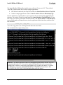
2. Observe the packets in the command console.
The above screenshot shows data captured by SerialDump, the packet is sent by XAccel
application. For details of the XAccel packet structure, please refer to section 6.6.2. As an
illustration, let us take a look at the last line of the data set:
126 0 50 125 64 32 1 218 0 185 0 127 0 172 3 185 0 128 0 173 3 …
The first group in blue is the TosMsg header (see table 6-1):
Address (2 bytes): 126
AM type (1 byte): 50
Group ID (1 byte): 125
Length (1 byte):
64
The next group in red is the sensor board header (see table 6-5):
Sensor-board ID (1 byte): 32
Packet ID (1 byte):
1
Node ID (2 bytes):
218
Next are the Accel sensor data, the group in green denotes 3 readings from X/Y/Z axis of the
sensor, each is 2 bytes. There are 10 groups in one packet.
Accel_X (2 bytes):
185
Accel_Y (2 bytes):
127
Accel_Z (2 bytes):
940
Doc.# 7430-0765-01 Rev. A
Page 31
Imote2.Builder Kit Manual
7.4 MFDeploy
Micro Framework deploy is a tool that can flash a program image in SREC format into the
Imote2, it can also erase the deployed application from the Imote2.
7.4.1 Starting the MFDeploy application
1. Start MFDeploy from Windows Start>Programs>Crossbow>Imote2.Builder>Tools>MFDeploy
2. From the Device dropdown, select USB. If the Mote is connected to the PC via USB and
reset button is pressed, the ID should show up in the right hand side textbox.
WARNING
After resetting the Imote2, you have a window of 2 seconds to hit the Deploy or Erase button if
you are to update the TInyCLR image or to erase the existing managed application. Missing this
time window will lead to an operation failure and the procedure needs to be redone.
Deploying a managed C# application is not subjected to this 2-second window.
7.4.2 Deploying an application to the Imote2
1. Click on Browse and navigate to the location where the .hex files reside, select the files
that you would want to flash.
Page 32
Doc.# 7430-0765-01 Rev. A
Imote2.Builder Kit Manual
2. Reconnect the USB cable to the Imote2 and push the Reset button.
3. Wait for the Imote2 ID to show up in the text box and while the green Led is still on,
click on Deploy button.
4. The program will be uploaded and start executing in the Imote2 once the Deployment
Status message disappears.
7.4.3 Erasing a deployed application
1. Reconnect the USB cable to the Imote2 and push the Reset button.
2. Wait for the Imote2 ID to show in the text box and while the green Led is still on, click
on Erase button.
3. A pop-up windows asks for confirmation for the operation, click on the Yes button.
4. The following window shows the progress of the erase operation.
; NOTE: This only clean up the managed application that is deployed to the Imote2, and it is
recommended if a corrupted application is deployed to the Imote2.
7.4.4 Crossbow pre-compiled srec files
Doc.# 7430-0765-01 Rev. A
Page 33
Imote2.Builder Kit Manual
The Imote2.Builder SDK installer installs some useful srec files to user’s PC. These include
TinyCLR Crossbow build, and Crossbow sample applications.
•
.NET Micro Framework (aka TinyCLR) resides in <Imote2.builder>\bin\srec\TinyCLR.
•
Crossbow sample applications reside in <Imote2.builder>\bin\srec\XBowSampleApp.
We also include the script that allows users to generate the srec file from their application bin
directory. The script is Create_Srec.cmd located in <Imote2.builder>\Tools\MFDeploy. To run
this script, you need to open a DOS command window, add <Imote2.builder >\tools\MFDeploy
to your search path, and change directory into the application folder bin\release, and then issue
this command:
Create_Srec
<app_name>
A srec file <app_name>.hex will be generated under the same folder.
The screenshot below capture this process.
; NOTE: The Imote2 hardware in the kit is configured from the factory with the TinyCLR
version included on the CD. If you need to update the TinyCLR with more recent version
available from Crossbow, you need to restore/update TinyCLR onto your Imote2. To do this,
start MFDeploy, navigate to <Imote2.Builder\bin\srec\TinyCLR and select these 3 files:
ER_CONFIG, ER_DAT, ER_FLASH and deploy them on to the Imote2.
Page 34
Doc.# 7430-0765-01 Rev. A
Imote2.Builder Kit Manual
7.5 MotePong
MotePong is a demo application that maps sensor control input from the XAccel firmware
application for use as a device controller in a simple Pong game. To start a game, first connect
an ITS400 equipped Imote2 running XAccel either directly through USB or via remote wireless
through an XSniffer base to the PC. Power all motes, and then start MotePong. To start game
play, select Game>New Game from the menu. The speed of the ball movement can be set from the
Difficulty menu.
The tilt measurement of the z-axis accelerometer is used to control the paddle. Hold the mote
vertically with the USB cable in between your middle and ring fingers. When the mote is
directly vertical, the paddle will be in the middle of the playing area. To move the paddle up to
the top of the screen, tilt the mote left. Horizontal left will place the paddle in the maximum
upward position. To move the paddle down to the bottom of the screen, tilt the mote right.
Horizontal right will place the paddle in the maximum downward position.
Doc.# 7430-0765-01 Rev. A
Page 35
Imote2.Builder Kit Manual
8 Developer API Reference
The Imote2.Builder SDK provides APIs for the various hardware subsystems on the Imote2
(IPR2400) and sensor board (ITS400) hardware. This section provides a brief description of the
API for various sub-system on the Imote2, for more detailed description, please refer to the
document generated by doxygen at Windows
Start>Programs>Crossbow>Imote2.Builder>document>API Reference Manual
Table 8-1. C# Classes included in Imote2.Builder SDK
HW Subsystem
Page 36
Namespace of Driver
C# Class of Driver
Radio
Crossbow.platform.imote2
Radio
USB
Croissbow.lib.utils
SerialDump
UART
Crossbow.platform.imote2
UART
LED
Crossbow.platform.imote2
Leds
I2C
Microsoft.SPOT.Hardware
I2CDevice
SPI
Microsoft.SPOT.Hardware
SPI
EEPROM
Microsoft.SPOT
ExtendedWeakReference
ITS400 sensor board
Crossbow.sensor.its400
Its400
Doc.# 7430-0765-01 Rev. A
Imote2.Builder Kit Manual
ADC
Crossbow.sensor.its400
Its400Adc
Accelerometer Sensor
Crossbow.sensor.its400
AccelerometerSensor
Light Sensor
Crossbow.sensor.its400
Its400Light
Temperature Sensor
Crossbow.sensor.its400
Its400Temp
Humidity Sensor
Crossbow.sensor.its400
TempHumSensor
8.1 Platform
The Crossbow.platform.imote2 namespace contains classes for low-level access to the mote
hardware.
8.1.1 LED
The LED functionality is wrapped in class Leds (Leds.cs).
To turn the LED on and off:
public
public
public
public
public
public
void
void
void
void
void
void
blueOn();
blueOff();
redOn();
redOff();
greenOn();
greenOff();
To Set LED to integer value from 0 to 7:
public void set(int i);
void setRGB (LedColor rgb)
LED Color enumeration values:
BLACK
RED
GREEN
BLUE
PURPLE
CYAN
YELLOW
WHITE
8.1.2 UART
UART class provides access to COM1 on the Imote2, its default setting is 115200, 8N1, no flow
control.
To write data to COM1:
public void Write(byte[] buf, int length)
To read data from COM1:
public int Read (byte[] recvBuf, int count, int timeout)
To flush COM1:
Doc.# 7430-0765-01 Rev. A
Page 37
Imote2.Builder Kit Manual
public
void
Flush()
8.1.3 Pins
Pins.cs contains class Pins, which defines the PXA271 GPIO lines available in the Imote2
hardware. This class provides a mapping of GPIO lines to type Microsoft.SPOT.Hardware
Cpu.Pin. In general, access to this low-level call should be reserved for authors of managed
drivers. Developers are encouraged to use higher-level abstractions of the hardware rather than
access these pins directly. A good example would be the LEDs, which should be accessed
through the LED class rather than directly through these pin mappings.
For driver authors, the pin mappings are used as references for instantiation of OutportPort or
InputPort objects. An example follows:
OutputPort greenLED = new OutputPort(Pins.GPIO_PORT_LED_GREEN, true);
greenLED.Write(true);
8.1.4 Interrupts
To enable interrupt on a GPIO pin:
public InterruptPort(Cpu.Pin portId, bool glitchFilter,
Port.ResistorMode resistor, Port.InterruptMode interrupt);
To assign the ISR (Interrupt Service Routine) to an interrupt:
<InterruptPort>.OnInterrupt += new GPIOInterruptEventHandler(<ISRMethod>);
The ISR has the following signature:
[MethodImpl(MethodImplOptions.Synchronized)]
private void ISRMethod(Cpu.Pin port, bool state, TimeSpan time)
8.1.5 Radio
The radio driver consists of 2 layers: PAL (Platform Abstraction Layer) and HAL (Hardware
Abstraction Layer). The former exists in namespace Crossbow.platform.imote2, the latter exists
in namespace Crossbow.radio.cc2420. Crossbow also provides TinyOS interoperability wrapper
library classes, which exist in namespace Crossbow.lib.utils.tos.
The application writer is given access to the native IEEE 802.15.4 capability on the Imote2
through the Crossbow.platform.imote2.radio class. This class will initialize the radio in 802.15.4
compatibility mode, and provides the standard radio API as defined by IRadioDevice for the
users.
8.2 Radio Driver
In this section we explain the radio APIs provided in the namespace Crossbow.radio.cc2420 and
Crossbow.lib.utils.tos
To set various radio options (Frequency, power, node address, PAN address):
public bool SetRadioOption
(RadioOption option, ushort val)
Page 38
Doc.# 7430-0765-01 Rev. A
Imote2.Builder Kit Manual
To send out a packet:
public bool Send
(ushort dstPanAddr, ushort dstAddr, byte[] data)
To send out a packet requesting acknowledgement:
public bool AcknowledgedSend
(ushort dstPanAddr, ushort dstAddr, byte[] data)
To turn on/off the receiver:
public void ReceiverOn(bool active)
To receive packet:
public byte[] ReceiveSrc
(ushort srcPanAddr, ushort srcAddr, int timeout)
public byte[] ReceiveAny
(ref ushort srcPanAddr, ref ushort srcAddr, int timeout)
8.2.1.1
Initialization
The radio can be initialized via the constructor in class Radio:
public Radio(ushort freq, ushort power,
ushort pan_address, ushort address);
The radio frequency and radio power are defined in 2 enums: RadioChannel and RadioPower.
public enum RadioChannel : ushort
{
Ch11 = 2405,
Ch12 = 2410,
Ch13 = 2415,
Ch14 = 2420,
Ch15 = 2425,
Ch16 = 2430,
Ch17 = 2435,
Ch18 = 2440,
Ch19 = 2445,
Ch20 = 2450,
Ch21 = 2455,
Ch22 = 2460,
Ch23 = 2465,
Ch24 = 2470,
Ch25 = 2475,
Ch26 = 2480
}
public enum RadioPower : ushort
{
M0DBM = 31,
M1DBM = 27,
M3DBM = 23,
M5DBM = 19,
M7DBM = 15,
M10DBM = 11,
M15DBM = 7,
M25DBM = 3
}
To set various radio options:
public bool SetRadioOption(RadioOption option, ushort val);
Valid options are:
LocalAddress = [0x0000, 0xFFFF]
PANAddress = [0x0000, 0xFFFF]
Channel
= [11, 26]
Frequency
= [2400, 2483] (MHz)
RFPower
= [1, 31] (1 := -25dBm, 31 := 0dBm)
Doc.# 7430-0765-01 Rev. A
Page 39
Imote2.Builder Kit Manual
8.2.1.2
Send/Receive
To send data:
public bool Send
(ushort dstPanAddr, ushort dstAddr, byte[] data);
Receive data sent to this device from a specified source or return null if no frame received within
a given timeout:
public byte[] ReceiveSrc
(ushort srcPanAddr, ushort srcAddr, int timeout);
To receive data sent to this device from any source or return null if no frame received within a
given timeout period:
public byte[] ReceiveAny
(ref ushort srcPanAddr, ref ushort srcAddr, int timeout);
8.2.1.3
TinyOS compatability
Note that TinyOS employs a specific 805.14 packet, we extend the radio support for TinyOS and
provided the functionalities in TOSRadio.cs:
TinyOS specifics (such as amType, groupID etc.) can be set via property in class TOSRadio.
The Receive method has been overriden to return the TosMsg.
A new method to support Promiscuous listening:
public TosMsg PromiscuousListening(int timeout);
To convert a 805.14 style TosMsg (such as used in MicaZ, Iris and TelosB) to standard TosMsg
format:
public byte[] ConvertToMica2Msg();
Please refer to section 8.4.6 for more of the TinyOS compatibility classes.
8.3 Sensors
Various sensor drivers exist in the namespace Crossbow.sensor.its400. Note that the sensor
board draws about 15mA current.
There is a facade class, Its400.cs, which wraps up all sensor classes and provides a simple
interface to the user applications, each of the sensors can be read from one of 2 read-only
properties: one for the raw reading, the other for the converted value with proper engineering
unit:
Page 40
Doc.# 7430-0765-01 Rev. A
Imote2.Builder Kit Manual
Table 8-2. Sensor properties provided by ITS400 class
Return Type
Name
Description
float
Adc0
Converted reading from ADC channel 0, in unit volt.
ushort
Adc0Raw
Raw reading from ADC channel 0
float
Adc
Converted reading from ADC channel 1, in unit volt.
ushort
Adc1Raw
Raw reading from ADC channel 1
float
Adc2
Converted reading from ADC channel 2, in unit volt
ushort
Adc2Raw
Raw reading from ADC channel 2
float
Adc3
Converted reading from ADC channel 3, in unit volt
ushort
Adc3Raw
Raw reading from ADC channel 3
float
AccelX
Converted reading from accel X axis, in unit G
ushort
AccelXRaw
Raw reading from accel X axis
float
AccelY
Converted reading from accel Y axis, in unit G
ushort
AccelYRaw
Raw reading from accel Y axis
float
AccelZ
Converted reading from accel Z axis, in unit G
ushort
AccelZRaw
Raw reading from accel Z axis
float
Light
Converted reading from light sensor, in unit Lux.
ushort
LightRaw
Raw reading from light sensor
Humidity
Converted reading from humidity sensor, in
percentage.
ushort
HumidityRaw
Raw reading from humidity sensor
float
TempSensirion
Converted reading from Sensirion temperature
sensor, in degree C.
ushort
TempSensirionRaw
Raw reading from Sensirion temperature sensor
float
TempCTI
Converted reading from TI temperature sensor, in
degree C.
float
TempFTI
Converted reading from TI temperature sensor, in
degree F.
ushort
TempTIRaw
Raw reading from TI temperature sensor
float
If you instead prefer not to use the façade class, but the individual sensor driver,
here is a breakdown of the managed sensor drivers:
8.3.1 Sensirion Temp/Hum sensor
In TempHumSensor.cs:
Public properties:
float
Hum: return the relative humidity reading in percentile.
float
TempC: return the temperature reading in degree C.
ushort HumRaw: return the raw reading of the relative humidity.
ushort TempRaw: return the raw reading of the temperature.
Conversion formula:
Hum = (-0.0000028)*HumRaw*HumRaw + 0.04*HumRaw
- 4
TempC = TempRaw * 0.01 – 39.6
Doc.# 7430-0765-01 Rev. A
Page 41
Imote2.Builder Kit Manual
8.3.2 TAOS Light sensor
LightSensor.cs:
Public member functions:
uint32 readLux10(): return the 10X value of the lux.
Public properties:
float
Light: return the light in lux.
ushort LightRaw: return the raw reading
Conversion formula:
The conversion is based on a look-up table that contains a set of coefficients,
please look at the implementation of function ReadLux10() in
LightSensor.cs in namespace crossbow.sensor.its400, or refer to the TAOS sensor
datasheet for the details.
8.3.3 TI Temperature sensor
TemperatureSensor.cs:
Public member functions:
int ReadDegreeC10(int timeout): return the 10X value of the
temperature in Celsius.
int ReadDegreeF10(int timeout): return the 10X value of the
temperature in Fahrenheit.
int readRaw(int timeout): return the raw reading from the sensor.
Public properties:
float TempC: return the temperature reading in degree C.
float TempF: return the temperature reading in degree F.
ushort TempRaw: return the raw reading
Conversion formula:
TempC = (TempRaw*10 + 8) / 1.6
8.3.4 ST Micro Accelerometer
AccelerometerSensor.cs:
Public properties:
float ChannelX:
return X axis accelerometer reading in unit G.
float ChannelY:
return Y axis accelerometer reading in unit G.
float ChannelZ: return Z axis accelerometer reading in unit G.
ushort ChannelXRaw: return X axis accelerometer raw reading.
Page 42
Doc.# 7430-0765-01 Rev. A
Imote2.Builder Kit Manual
ushort ChannelYRaw: return Y axis accelerometer raw reading.
ushort ChannelZRaw:
return Z axis accelerometer raw reading.
Conversion formula:
ChannelX = ChannelXRaw / 980
8.3.5 Maxim ADC
ADCSensor.cs:
Public properties:
float Channel0: return ADC channel 0 reading in volt.
float Channel1: return ADC channel 1 reading in volt.
float Channel2: return ADC channel 2 reading in volt.
float Channel3: return ADC channel 3 reading in volt.
ushort Channel0Raw: return ADC channel 0 raw reading.
ushort Channel1Raw: return ADC channel 1 raw reading.
ushort Channel2Raw: return ADC channel 2 raw reading.
ushort Channel3Raw: return ADC channel 3 raw reading.
Conversion formula:
ChannelX = ChannelXRaw * 3 / 4096
; NOTE: The ADC reading is a value between 0 and 3V, the voltage applied to the ADC
channel. If the voltage is greater than 3v, it is capped at 3V.
8.4 Utilities
The Crossbow.lib.utils namespace contains a number of utility classes.
8.4.1 CRC
Compute CRC (Cyclical Redundancy Check) of a packet.
8.4.2 HDLC
Implement a byte stream framing using PPP-HDLC like protocol (See RFC 1662).
8.4.3 SerialDump
A class that dumps message over the USB port.
To dump a byte array to USB
static void
print(byte[] str)
To dump a string to USB:
Doc.# 7430-0765-01 Rev. A
Page 43
Imote2.Builder Kit Manual
static void
print(string str)
8.4.4 UniqueID
Allows applications to read out information including SerialID, SKU, OEM, UID etc.
8.4.5 PowerManagement
Implement the power management API, such as putting the mote to deep sleep (drawing 525 uA)
for a specified period of time.
To put the mote into deep sleep mode, call the following method:
PowerManagement
pm = new PowerManagement();
pm.DeepSleep(30);
The mote will go into deep sleep state for 30 seconds.
The PowerManagement class contains the following member functions:
void DeepSleep(uint duration)
void SetCoreFreq (uint freq)
uint GetCoreFreq ()
void SetCoreVoltage(uint vltg)
float GetCoreVoltage()
uint GetResetCause()
Currently only DeepSleep is implemented. The rest are to be implemented in the future release.
WARNING
When the Imote2 recovers from the deep sleep state, it is a reboot. For information that needs to
be preserve over reboots, it has to be written to the flash. The sample application
XSensorITS400Sleep demonstrates how to accomplish this by using ExtendedWeakReference.
8.4.6 TinyOS Compatibility
The Crossbow.lib.utils.tos namespace contains a number of utility classes for simplifying
TinyOS compatibility. This allows the Imote2 to interoperate with MicaZ, Iris and TelosB
motes.
The following classes exist in namespace Crossbow.lib.utils.tos:
8.4.6.1
TosMsg
This class encapsulates the TinyOS packet that works with 802.15.4 radio, which is used with
MICAz, IRIS and TelosB Motes.
The following method converts the message to the default TosMsg format:
Byte[]
Page 44
ConvertToMica2Msg()
Doc.# 7430-0765-01 Rev. A
Imote2.Builder Kit Manual
8.4.6.2
TOSMac
TinyOS compatible radio driver, a wrapper classes of the RadioCC2420 class.
The AM type and group ID can be initialized through the constructor:
Public TOSMac(byte am_type, byte group_id)
Or application can perform get/set operations on the public properties amType and groupId.
By default the AM type is set to 1, the group ID is set to 125.
8.4.6.3
TOSRadio
This class handles the initialization of the TinyOS compatible radio driver.
8.4.6.4
TOSSerialDump
This is a subclass of SerialDump, it prints out a string to USB port, with the TOS header
appending to the beginning.
static
void
printWithTosHeader (byte[] str)
this method sends “TosMsg_header + str” to USB port.
The AM type and group ID field of the TosMsg header can be initialized by setting the
corresponding properties. By default, AM type is 0x04, group ID is 0x7D.
Doc.# 7430-0765-01 Rev. A
Page 45
Crossbow Technology, Inc.
4145 N. First Street
San Jose, CA 95134
Phone: 408.965.3300
Fax: 408.324.4840
Email: [email protected]
Website: www.xbow.com