1
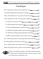
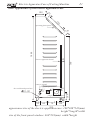
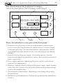
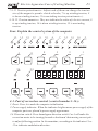
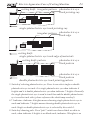
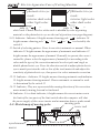
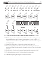
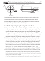
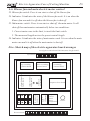
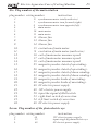
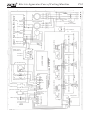
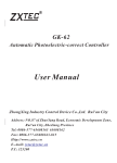
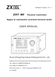
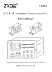
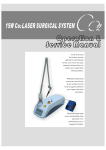
R
Electric Apparatus Case of Cutting Machine
User Manual
ZhongXing Industry Control Device Co.,Ltd,Rui’an City
Address: NO.87 of ZhaoYang Road, Economic Development Zone,
Rui’an City, ZheJiang Province
Tel: 0086-577-65608165 65608162
Fax: 0086-577-65608163-815
Http://www.zxtec.cn
E-.mail: [email protected]
P.C: 325200
R
Electric Apparatus Case of Cutting Machine Catalogue
Catalogue
One. Appearance of the electric apparatus case
P1
Two. Sketch map of the front-panel arranges
P2
Three. Introduction to e very part of the front-panel
P2
Four. Explain the control system of the computer
P3
4-1. Part of correction control
P3
4-2. Sketch map of moving pole
P6
4-3. Part of length and pace measurement
P6
4-4. Method of length and pace measurement
P7
4-5. Method of setting length and girth controlled
P7
4-6. Blower fan and main electric motor control
P8
Five. Sketch map of the electric apparatus board arranges
P8
Six. Plug number of the main aviation
P9
Seven. Plug number of the photoelectric eye
P9
Eight. Principle pictures of the electric apparatus
P10
Inform respectfully customer: You must read the manual
first and connect with the machine well and connect earth
wire of the electric apparatus case.
R
Electric Apparatus Case of Cutting Machine
P1
One. Appearance of the electric apparatus case
25
100
3
29
operating front-panel
25
0001
740
60
electric apparatus board
connect ground
plug of the photoelectric eye
6.5
40-60
16
50
plug of the lord outputs
100
50
60
70
300
140
the scale board opens bore
120
appearance size of the electric apparatus case: 100*300*510(mm)
height*length*width
size of the front-panel window: 464*293(mm) width*height
R
Electric Apparatus Case of Cutting Machine
Two. Sketch map of the front-panel arranges
size of the front-panel: 460*290(mm) width*height
1 P2
8 7 10 9 4 12
11 6 5 3 2 Three. Introduction to e very part of the front-panel
1. Computer control system: It consists with automatic photoelectriccorrect controller, length controller which can preset control length
to automatically stop, line speed instruments, main machine control
switch and blower fan control switch ( see in detail page elucidation
behind ).
2. Control switch of the power supply: It is used to open or close the
control power supply of control box ( notice: this switch closes control
power supply only ).
3. Power supply indicator: Indicating the power switch is placed in to
open or closes appearance.
4. Voltmeter: Indicate electric voltage of the power supply inputs (normal
value:180-245 V, please close the power switch when the input voltage
is not on the normal value ).
5. Potentiometer of main motor: Regulating it can change the speed of
the main motor.
6. Tachometer of the main motor: It shows the speed when the main motor
revolves.
R
Electric Apparatus Case of Cutting Machine
P3
7.9.11. Tension potentiometer: Adjust each of them can change the tension
size of the magnetic-powder clutch or brake ( 7 is up winding tension, 9
is down winding tension, 11 is unwinding tension potentiometer ).
8.10.12. Tension ammeters: They are indicate the value of electric current, 8
is up winding tension, 10 is down winding tension, 12 is unwinding
tension.
Four. Explain the control system of the computer
15
15
12
13
10
6
9
AUTO
HANDWORK
4
11
SINGLE
DOUBLE
8
<
<
<
<
7
14
2 14
16
5
LIMIT BIT POWER SUPPLY
3
1
POLE GENDER
>
PATTERN
>
ELECT. EYE
RESET
18
24
26
RUN
17
RUN
M/min
LENGTH DISPLAY
MAIN
MOTOR
BLOWER
25
23
-
22
+
21
SETUP
CLR
20
19
4-1. Part of correction control ( control number 1-16 ):
1. Reset: Press it to make the computer initialization.
2. Power supply indicator: When the indicator brights means power supply of the
computer parts are placed in power supply appearance.
3.4. Direction switch: Press homologous direction switch 3 or 4 will make the
correction motor to be turning forward or backward that moving correct pole
to adjust following position. In the meantime, according to the indicator 14 or
15 to indicates ambulation direction .
R
Electric Apparatus Case of Cutting Machine
cutting knife irregular pattern
P4
photoelectric eye
track printing ray
single photoelectric eye track printing ray
photoelectric eye
irregular pattern
track edge
cutting knife
single photoelectric eye track edge of materials
cutting knife pattern
photoelectric eye
track pattern
photoelectric eye
track pattern
double photoelectric eye track printing pattern
5. Switch of selecting photoelectric eye: Press it can select single or double
photoelectric eye to track. It is single photoelectric eye when indicator 6
brights and it is double photoelectric eye when indicator 7 brights. Generally
the single photoelectric eye is used to track line and the double photoelectric
eye is used to track side ( please reference the sketch map overleaf ).
6.7. Indicator: Indicator 6 brights means choosing single photoelectric eye to
work and indicator 7 brights means choosing double photoelectric eye to
work. Single or double photoelectric eye is selected by the switch 5.
8. Switch of choosing pole: Press"pole" switch can choose black or white to
work, when indicator 9 brights is on black work, indicator 10 brights is on
R
Electric Apparatus Case of Cutting Machine
photoelectric eye
track:
interior dark color
other light color
pole is“ ”
P5
photoelectric eye
track:
interior light color
other dark color
pole is“ ”
white work. Choose black or white work is decided by color of printing
material or the photoelectric eye on the trail of position (saw page diagram).
9.10. Indicator: Indicator 9 brights means choosing pole “ ”, indicator 10
brights means choosing pole “ ”. Pole “ ” or “ ” is selected by the
switch 8.
11. Switch of selecting pattern: Press it can select automatic or manual. When
indicator 12 brights means the appearance of automatic and indicator 13
brights means the appearance of manual. Generally to operate the correct
controller, please select the appearance of manual first according to the
color and the type of the correction material to select pole and single or
double photoelectric eye. Press the direction switch to adjust photoelectric
eye to match precision the side or line of the track material and adjust the
sensitivity of photoelectric eye, then press it to select automatic correction.
12.13. Indicator: Indicator 12 brights means choosing automatic and indicator
13 brights means choosing manual. Choose automatic or manual to work
is determined by the switch 11.
14.15. Indicator: They are represented the running direction of the correction
motor namely turning forward or backward.
16. Indicator: It is a limit indicator, it brights means the correct motor run to
the limit of the two ports of the limit switch when the computer will shut
the power supply of the correct motor and at meantime buzzer sends sound.
4-2. Sketch map of moving pole:
synchronous
motor
limit switch
moving pole
screw rod
Electric Apparatus Case of Cutting Machine
15
15
12
13
10
6
9
<
AUTO
HANDWORK
4
11
SINGLE
DOUBLE
8
<
<
P6
7
14
2 14
16
<
R
5
LIMIT BIT POWER SUPPLY
3
1
POLE GENDER
>
PATTERN
>
ELECT. EYE
RESET
18
24
26
RUN
17
RUN
M/min
LENGTH DISPLAY
MAIN
MOTOR
BLOWER
25
23
-
22
+
SETUP
21
CLR
20
19
4-3. Part of length and pace measurement (number 17-22):
17. Window of pace shows: If main motor 25 is on, it shows cutting pace of
the cutting machine (unit: M/min); If main motor 25 is off, it shows “-P-”
which means the machine is stop; When it shows “-L-” means the computer
is setting length.
18. Window of length shows: It shows the cutting length (unit: M).
19. Zero clearing/ shift switch: Press it on the state of setting can move set
position to change the data quickly. Normally to press it can clear the data
of length.
20. Set up switch: Used to set the control length and the perimeter of roll.
21.22. Add and subtract switch: Used to adjust the setting data.
4-4. Method of length and pace measurement:
R
Electric Apparatus Case of Cutting Machine
measured material
P7
perimeter
alnico
2-
3M
Hall switch
affix alnico
Length measure adopts Hall switch to pick up every pulse and get the
length according to the preset perimeter cumulation method. Speed
measure adopts frequence of Hall switch multiply the preset perimeter
to compute the speed (see above sketch map ).
4-5. Method of setting length and girth controlled
1. Set perimeter: Press the switch “set” tightly until the window of speed
to display “-C-”, then loose. Now the window of length to display the
storage perimeter data last time (unit: M) and scintillation to prompt
change position, press “+” or “-” to adjust data and press “CLR/move”
switch to move change position to arrive the data of perimeter needed
and then perimeter set when the window of length to display “00000”.
2. Set the control length: Press the switch “set” a time, the window of
speed to display “-L-” and the window of length to display the storage
control length last time (unit: M) and scintillation to prompt change
position. Press “+” or “-” to adjust data and “CLR/move” switch to
move change position to arrive the data of control length needed and
then press “set” switch, window of length to display “save”, it is
finished the length set when the window of length to display “00000”.
Notice: Set the needed control length, the machine run to subtract speed
automatically before 3 miles of the control length (speed is adjusted
by the base potentiometer of the electronic board) and stop the machine
when it run to the preset length.
It will not stop machine automatically when the control length is set 0.
R
Electric Apparatus Case of Cutting Machine
P8
4-6. Blower fan and main electric motor control
23. Blower fan switch: Press it can start or shut off the blower fan.
24. Indicator: It indicates the state of the blower fan work. It is on when the
blower fan run and it is off when the blower fan is shut off.
25. Main motor switch: Press it can start or shut off the main motor. It will
shut off then main motor automatically below two conditions:
1. Correct motor runs to the limit, ie touch the limit switch.
2. The measured length arrives the preset control length.
26. Indicator: It indicates the state of main motor work. It is on when the main
motor run and it is off when the main motor is shut off.
Five. Sketch map of the electric apparatus board arranges
size of glue wooden board:580*490 (mm) height*width
up terminal
down rewinding
tension board
blower
fan
contactor
main motor
contactor
feedback
potentiometer
slipper bad motor
baffle-board
slipper bad motor
baffle-board
up rewinding
tension board
main line circuit C45 circuit-breaker
down terminal
unwinding
tension board
computer drive board
computer
tension
board
power
transformer
buzzer
R
Electric Apparatus Case of Cutting Machine
P9
Six. Plug number of the main aviation
plug number wiring number
1.
2.
3.
4.
5.
6.
7.
N
7
8
9
10
11
12
8.
9.
10.
11.
12.
13.
14.
15.
16.
17.
18.
19.
20.
21.
22.
23.
24.
25.
26.
13
14
15
N
16
17
18
25
26
32
33
39
40
48
49
50
53
54
48
instruction
synchronous motor total(earth wire)
synchronous motor turn forward (right)
synchronous motor turn opposite(left)
main motor
main motor
main motor
blower fan
blower fan
blower fan
excitation of main motor
excitation of main motor(earth wire)
coil of main motor measure speed
coil of main motor measure speed
coil of main motor measure speed
magnetic powder clutch of up windingmagnetic powder clutch of up winding+
magnetic powder clutch of down windingmagnetic powder clutch of down winding+
magnetic powder brake of unwindingmagnetic powder brake of unwinding+
0V electric power supply
12V electric power supply
input the signal of Hall switch
right limit switch of correction
left limit switch of correction
0V electric power supply
Seven. Plug number of the photoelectric eye
plug number wiring number
1.
2.
3.
49
55
48
instruction
12V electric power supply
input single of photoelectric eye
0V electric power supply
R
Electric Apparatus Case of Cutting Machine
P10
blower fan
leg of a
circuit
power supply switch
slipper bad motor
C45 circuit-breaker
voltmeter
output
earth wire
power indicate
potentiometer
down rewinding
potentiometer
put material
potentiometer
-NI+
constant current tension
buzzer
AC power input
Hall switch
-NI+
photoelectric eye
constant current tension
limit switch
OUT+
OUT-
AC15V
input
open
close
right limit
left limit
photoelectric eye
single eye
Hall switch
buzzer
AC50V
main motor
limit switch
OUT+
OUT-
AC15V
turn left
turn right
blower fan
magnetic powder clutch
main motor contactor
input
interface
blower fan contactor
AC50V
resistance
capacitance
magnetic powder clutch
synchronous motor
20 core computer drop-out line
front-panel
resistance
-NI+
resistance
OUT+
OUT-
AC15V
adjust speed
potentiometer
AC50V
magnetic powder clutch
adjust speed
potentiometer
constant current tension
measured coil
up rewinding
table
feedback
potentiometer
table+
tachometer
slipper bad motor baffle-board
C45 circuit-breaker
transformer