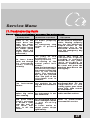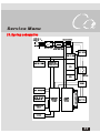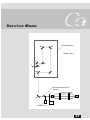
1
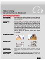
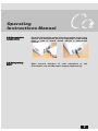
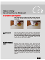
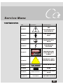
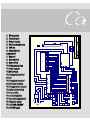
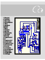
15W Co 2 LASER SURGICAL SYSTEM
This manual
includes some
general warnings
that you have to pay
special attention to
when you operate
the system.
Please read this
manual carefully
and understand
thoroughly before
you operate this
system.
Please keep the
manual beside the
system for
reference on a
regular basis.
TABLE OF CONTENTS
Safety Guidelines
1
Preface
2
Warning
2
Operating Instructions Manual
1. Operation Principle of the system
3
2. Name of the components
5
3. Pre- startup Preparations
6
4. Installation and adjustment
8
5. Operation Procedures
10
6. Protection and Alarm
12
7. Pilot Beam
13
8. Precautions
14
9. Maintenance
16
10. Accessories
17
Service Manu
11. Troubleshooting Guide
20
12. Technical Specification
22
13. System Schematics
23
14. Warranty and Service
25
15. Warnings, Identification and Labels
26
Safety Guidelines
The following information is provided for the correct utilization
of CO 2 laser surgical system. The information includes not only
the accident protection regulations the products comply with,
but also the effective precautions regarding proper use of the
products.
The safety regulations that PC015-A series CO 2 laser surgical
system comply with can be grouped under 3 categories
1. Electric safety regulation
2. Laser radiation safety regulation
3. Electromagnetic radiation safety regulation
These safety regulations comply with the following standards
set by IEC:
IEC 60601-1 1998+A1: 1991+A2: 1995
Medical electric equipment part 1: General requirements for
safety IEC 60601-1-2: 2000
Medical electric equipment general requirement for safety
collateral standar d: electromagnetic compatibility
requirement and test
IEC 60601-1-4: 2000
Medical electric equipment general requirement for safety
collateral standard: programmable medical electric equipment
IEC 60602-2-22: 1995
Medical electric equipment part2, specific safety requirement
on diagnosing and treatment laser equipment
IEC 60825-1: 2001
Radiation safety for laser product, equipment classification
requirement and user's guidance.
IEC 1441: 1997
Risk analysis
Although PC015-A series CO 2 laser surgical systems are
designed according to accident prevention regulations, only a
proper and careful use an guarantee safety. For effective
precautions, please refer to chapter3..4.5.8 and 9 in operator's
manual.
The EMC performance of this system has been evaluated and
is in compliance with En 60601-1-2.Better use this system in
an environment free of strong electromagnetic field.
1
Preface
The PC015- A CO 2 laser surgical system is an intelligent laser
treatment instrument. This product is featured by compact
str ucture, beautiful appearance, reliable perfor mance,
convenient operation and perfect safety. The technical
specifications of the product have latest the advanced
international standard.
The instrument can be applied to general surgery, gynecology,
otolaryngology, dermatology and cosmetology etc for different
treatment such as cutting, vaporizing, cauterizing and
solidifying. It can be used in ward and private clinics for its
portability and compactness.
WARNING
T his instr ument gener ates high
voltages and laser radiation within
the cabinet. Oper ator s must pay
m u ch at t e n t i o n t o s a fe t y d u r i n g
operation. Operation safety
instr uctions are specified in this
manual. Any improper use,
adjustment or maintenance may
cause laser r adiation hazar ds or
high-voltage electric shock.
2
Operating
Instructions Manual
1. Operation principle of the system
1. 1. Principle
of CO2 laser
surgical
system
The CO 2 laser, with a specific wavelength of 10.6um
can be absorbed by human body tissue (no matter
what color the skin is) almost by 100%, with the laser
slightly passing through the skin. It is the heat and
electromagnetic effect of the laser that people use to
conduct non-blood or less-blood cutting, cauterizing,
gasification and accurate microsurgery. Most optical
knives use CO 2 laser source.
1.2. System
description
The PC015-A CO 2 laser surgical system is the latest
microprocessor-controlled instrument based on a
sealed-off CO 2 laser providing up to 15W output power
on body tissue. It is easy and safe to operate.
1.3.Main
cabinet
1.CO 2 laser and compound light source
2.Switch source with high voltage and constant
current
3.Main control panel
4.Cooling system
5.Footswitch
6.Articulated arm
1.3.1CO2 laser
and compound
light source
Sealed-off laser is selected. The active medium is a
mixture of CO 2 and other compound gases. The
compound light consists of sealed-off CO 2 laser tube,
light intensity detector, diode laser and beam
combiner. The beam combiner combines CO 2 laser
beam and beam diode laser beam coaxially and
guides them into the articulated arm beam delivery
system.
1.3.2 Switch
source with
high voltage
and constant
current
The instrument is equipped with a switching-mode
power supply which converts input voltage to the high
voltage required for laser emission. Compared with
traditional source, it has a series of advantages, such
as small volume, high efficiency and safety while
increasing voltage.
3
Operating
Instructions Manual
1.3.3 Main
control panel
The microprocessor-based main panel is used to
control all functions by touching the thin film switch.
Time and power are displayed digitally, which is clear
and accurate.
1.3.4 Laser
cooling system
The laser cooling system is a closed circulating loop.
The coolant (distilled water or ion water) is circulated
by a pump.
1.3.5 Footswitch
A footswitch is used to control laser output. When the
footswitch is pressed, the shutter opens and laser
emits from the articulated arm.
1.3.6 Articulated
arm
The laser beam delivery system consists of lightweight, spring-balanced, 7-joint articulated arm. The
working radius of the ar ticulated ar m at full
extension is 110cm.
4
Operating
Instructions Manual
2. Name of the components
1. Articulated arm
2. Interlocks switch
1
3. Footswitch
4. Emergency stop
button
4
5. Controlled panes
2
5
3
5
Operating
Instructions Manual
3. Pre-startup preparations
3.1. Upacking
and inspection
After unpacking, please check to ensure that the
instrument is not seriously damaged, circuit lines are
well connected and accessories are available (see
accessories list)
3.2. Pouring
coolant
Unscrew with a screwdriver 6 small screws on the
instrument, which are used to fix the upper cover.
Open the upper cover and the cap of the water tank
carefully and pour clean water (or distilled or ion
water if available) into the tank through a hose (f5f10mm) till it is full. Then close the cover. Don't open
the cover r ecklessl y unless for the sake of
transportation. When filling water, be sure not to let
the water overflow. If water overflows, wipe with dry
cloth or dry it with an electric hair-fryer to avoid short
circuit or electric shock.
Never turn on power when the tank
is empty.
Screwdriver screws
Pouring water
3.3.Checking
power voltage
Ensure that the power voltage complies with the
requirement of the instrument. Socket is in working
order.
3.4.Connecting
power cable
Plug the two terminals of the power cable into the
power input socket and the power socket. (Make sure
the ground socket is in working order.)
6
Operating
Instructions Manual
3.5.Footswitch
connection
3.6.Temporary
start
Plug the footswitch cable into the socket on the rear
part of the instrument. Push in alignment of the notch
until a tone is heard which means a successful
lockup.
After several minutes of trial operation of
instrument, cut off the power supply temporarily.
the
7
Operating
Instructions Manual
4. Installation and alignment
Insert the key into the hole of the lock on the panel
and clock wisely by 90 , then the power supply is
turned on, and the water pump and cooling fan are
started up.
4.1 Articulated
arm
4.2 Adjustment of
Co2 laser emission
4.2.1
CO 2 laser beam delivery arm consists of an alignment
tube articulated arm focusing tip, focus-setting tube,
divergent physiotherapy head and a connector base.
The connector base is fixed on the output terminal of
the laser instrument. Usually the only thing required
to do is to install the articulated arm on the
connector base and lock it tightly.
Release the beam deliver y ar m and hold the
alignment tube to the connector base. Align the laser
beam to center of the alignment tube to enable the
CO 2 laser beam to travel along the axis of alignment
tube. Start the instrument and choose the lowest
output power (about 1W). Check light spot (such as
double spots or double beams). Locate the laser spot
at the end of the alignment tube with a piece of
sulphuric acid paper while keeping on adjusting the
system till laser beam travel through the entrance
center of the alignment tube. Release the alignment
tube and reinstall the delivery arm by screwing up
tightly.
8
Operating
Instructions Manual
4.2.2
Generally, a focusing tip is used to for operation. As
to large area cauterizing surger y, remove the
focusing up and install focus-setting tube and focussetting tip to control beam spot.
4.3. Aligning
pilot beam
Adjust the red diode laser as the aforesaid method,
till its laser spot converges with that of the CO 2 laser.
9
Operating
Instructions Manual
5. Operation procedures
CAUTION: Any operation in a manner other than
specified hereunder may cause the hazard of laser
radiation.
5.1. Start main
power supply
Rotate the key switch and turn on the power supply.
5.2. Function
selection
Press function key "STBY" and the indicator
illuminates, indicating the instrument is in "STBY"
state. Set laser radiation parameters according to the
need of operation.
5.3 Operation
mode selection
5.3.1 CONT
The system is set to "continuous" state. The laser
will emit-continuously according to the duration the
footswitch is pressed down.
5.3.2 REPT
The system is set to "repetation" state. The laser
emit intermittently according to the pulse duration
set previously when the footswitch is pressed.
5.3.3 SUPER
PULSE
The system is set to "super pulse" state. Laser emits
intermittently according to the setting super pulse
duration when the footswitch is pressed. After the
system is in "READY" state, if turned to the "STBY"
state again, the specifications remain unchanged. At
that time, the footswitch does not work.
5.4 Power and
time setting
5.4.1 Power
setting
The laser output power ranges from 0.5 to 15W.
Adjust laser power by pressing the "up" key( ) or
"down" key( ) under the display window.
Power Range (W)
0.5~1.0
1.0~10
10~15
Power Setting Increment (W)
0.1
0.5
1.0
10
Operating
Instructions Manual
5.4.2 Time
setting
a)When the system is in "CONT" state, the digital
reading of time will be "999".
b)When the system is in "REPT" state, the initial time
is "0.05" second. The maximum is "1" second. The
time range id from 0.05 to 1 second. Each press on
the up/down key increased/decresess time by "0.01"s.
c)When the system is in "SUPER PULSE" state, the
initial time display is "0.02" sec, (pulse duration).
5.5. READY state
After the above setting, set the function key to READY
state.
5.5.1
When the instrument is set to "READY" state, the
green alarm lamp (laser output indicator) flashes
intermittently, indicating the laser is ready to emit
(the buzzer doesn't beep) when the footswitch is
pressed, the laser output shutter opens, laser beam
emits, the alarming lamp illuminates steadily and the
buzzer beeps. Then the laser works according to the
parameters set previously.
5.5.2
When the instrument is in "READY" state, the
operation keys of the system do not work when
pressed. Before changing the mode of operation,
switch the function key to "STBY" state first.
5.5.3
When the instrument is "READY" state, if it is turned
to "STBY" state again, the parameters remain
unchanged, and the footswitch does not.
11
Operating
Instructions Manual
6. Protection and Alarm
6.1 Indication of
coolant circulation
When the water pump begins to work shortly after the
power is turned on, the coolant doesn't circulate
normally, with the indicator flashing and the buzzer
beeping. After the coolant circulates normally and
the warning device, which will alarm in case of no
water, is connected, the alarm stops beeping..
6.2.Overheat
protection
Prevent the instrument from being overheated: when
the temperature of the circulating water is higher
than 40C, the indicator will flash and the buzzer will
beep. Before normal operation is restored, cut off
power supply and wait till the temperature of cooling
water goes down below 25C. Then restart the
instrument. In case of the two aforesaid alarming
states, if the footswitch is pressed, laser will not
emit.
12
Operating
Instructions Manual
7. Pilot beam
In view of the invisibility of the 10.6um CO2 laser, a
visible red diode laser emitting coaxially with CO2
laser is provided to help the operator locate laser
beam conveniently. Press the key, the red light emit,
and a green indicator flashes. Press the key again,
the red light stops emitting, and the green indicator
extinguishes.
13
Operating
Instructions Manual
8. Precautions
8.1
Never let the laser beam be directed to human eyes or
healthy skin.
8.2
To prevent human eyes or skin from being hurt by the
reflection of laser light, never allow the laser beam,
be directed to any smooth reflective surface, such as
stainless steel device surface mirror surface, etc.
8.3
If 75%, alcohol is used to clean or sterilize relevant
part of the instrument, don't use the instrument till
the alcohol vaporizes. Never operate the instrument
in the presence of flammable anesthetics.
8.4
In order to prevent the focus lens of the handpiece
from being polluted and to keep a clear view of the
surgical area, a smoke evacuator is recommended to
the operator. The handpiece and focus lens must be
cleaned every 3 months.
8.5
The laser beam generated by this instrument is
hazardous to eyes in the area within 35m from the
instrument (when someone is staring directly at the
laser) operators must use safety eyewears when
operating.
8.6
This instrument generates high voltages inside. No
attempt should be made by non-professional to open
the cabinet of the instrument to avoid electric shock
resk.
8.7
If the instrument gives out abnormal smell or sound,
stop operation at once. Cut off the power first before
any inspection.
The laser tube in made of glass.
Handle with care to avoid damage.
14
Operating
Instructions Manual
8.8
Keep the instrument in an environment with the
temperature between 1C~50C and the relative
humidity between 10%~80%.
8.9
Empty the water tank before transportation
prevent the laser tube from being frozen to break.
8.10
Don't leave around laser tube and the instrument
recklessly when their service lives end. Recycle
according to the local environment protection
regulations.
8.11
To avoid improper use of the instrument, remove the
key from the keyswitch and keep it properly when the
instrument is not in use. The instrument generates
high voltages within the power supply and laser tube.
Please refer to professional per sonnel for
maintenance to avoid electric shock.
8.12
Operation room should bb equipped with a dust or
fume exhauster, because the dust arising during
operations may be mixed with biological tissue
particles.
to
15
Operating
Instructions Manual
9. Maintenance
The instrument generates hegh voltages within power
supply and laser tube. Refer to professional personnel
for maintenance to avoid electric shock.
9.2 Lens cleaning
The output power may drop slightly after the
instrument has been put into use for half a year. This
may be caused by the stained focus lens of the
handpiece. Wipe the lens gently with moistened
cotton ball once or twice. Be sure not to damage the
lens.
9.3 Cobinet
cleaning
If there is dirt on the cabinet, wipe gently with
moistened cotton cloth and some detergent or
toothpaste. Don't use over-wet cloth in case the water
leaks into the inner part of the instrument, causing
short circuit and damage. Please refer to chapter 9
for precautions.
9.4 Power
calibration
The practical laser output power and the preset panel
power must be calibrated each year with standard
laser power meter within validity period by trained of
professional personnel.
9.5 Fuse
replacement
Open the fuse holder with a screwdriver and remove
the original fuse. Before replacement, check and
ensure the new fuse is identical in type and
specification to the original one (220V/2A) to avoid
damage arising from unfit fuses.
9.6 Handpiece
sterilization
Handpiece must be sterilized after use. Refer to
chapter 8.3 for details.
16
Operating
Instructions Manual
10 Accessories
Operator's manual and service manual
1copy
Articulated arm
1pc
Power cable
1pc
Footswitch
1pc
Interlock key
2pcs
Fuse
2pcs(spare parts)
(Connecting wires recommended: 0.15*23)
handpieces (see table below)
17
Operating
Instructions Manual
Handpieces Accessories
D WG N O.
FIGURE
JH-DT-10
JH-DT-11
JH-DT-12
JH-DT-13
JH-DT-14
JH-DT-15
18
Ser vice Manu
11. Troubleshooting Guide
Please refer to professional personnel for maintenance
S Y M P TO M S
After the main
power is on, the
panel does not
light, the water
pump does not
work either, (when
the water pump
works, there are
slight vibr ation
and sound.)
No laser beam
emits out though
the instrument
seems running
normally.
No laser emits.
The instrument
alarms.
P O S S I B L E C AU S E S
AC T I O N S
The power plug has
not been proper ty
plugged.
The emergency stop
switch is pressed
down.
Check the two plugs at
the two ends of the power
cable. Replug proper ly
turn the red mushroomshaped button of the
emer gency key in the
indicated dir ection to
have the emergency key
connected.
The plug of the
footswitch is not
properly inserted.
The setting of the
control panel isn't
suitable.
When the instrument is
used for the first time,
after water is filled the
cover is not closed
tightly. The interlock
keys are not pressed
down. The joint of the
ar ticulated ar m is
loosened.
T he instr ument has
been working for too
long and the coolant is
too hot.
Insert the plug of
footswitch tightly
according to operator's
manual.Set the panel
again according to
operator's manual.Close
the cover and press the
interlock keys.Screw the
joint tightly.
Stop running the
instrument.Wait till the
temperature of the
cooling water goes down
below 25C, then restart
the instrument.
Place the instrument on a
The instrument
makes big noise The instrument is not stable and flat surface.
Well- balanced.
when running
Re d p i l o t b e a m
doesn't converge
or doesn't emit
from the end of
the tube. CO2
laser is off the
center.
The articulated arm is
either damaged inside R e f e r t o p r o f e s s i o n a l
o r n o t w o r k i n g personnel for service.
normally.
No laser emits or
output power dr ops
significantly.
19
Ser vice Manu
Note: Operators are not allowed to
adjust the components listed
below:
Laser tube, ar ticulated ar m, diode
pilot beam, microprocessor board.
20
Ser vice Manu
12. Technical Specification
Laser Type
Laser Wavelength:
Laser Mode:
Output Power:
Focus Spot Diameter:
Divergence:
Lens Focal Distance:
Power Instability:
Delivery System:
Sealed off CO 2 laser
10.6 microns
Low-valance mode
0~15W. cont adjustable
0.4mm
4mrad
F=100mm
+10%
Spring-balanced 7-joint
articulated arm
Touching switch
Microprocessor- controlled
Continuous,single
Operation and control:
Working Modes:
pulse,
Pulse Duration:
Display:
Cooling System:
Power Supply:
repeat pulse
0.05~1s
Power, time (digital display)
Closed loop circulating water
AC 220V, 50Hz
(see supply circulating
water)
Input Power:
Environment Temperature:
Relative Humidity:
Weight (kg)
Atomospheric pressure:
Warning up time:
Electromagnetic requirement:
Other working conditions:
300VA
5~40C
<80%
18kg
86.0kpa~106.0kpa
5min
No electromagnetice
Field interference
No obvious vibration
or airflow
Specifications subject to change without notice
21
Ser vice Manu
13. System schematics
110 V AC or
220 V AC
F1
T R AN SFO RM E R
F2
KEY SW I TC H
EM E RG ENC Y
ST OP SWI TC H
RE CTI FI E R
RE C TI FIE R
C O OL ANT P U MP
C OM PU T ER
P O WE R SU PP LY
FAN
F O OT
C W IT CH
FAN
RE LAY
WATER CUT-OFF
PROTECTION
C OMP UT E R
C O NT R OL
B O ARD
P OWE R
SUP PL Y
B OAR D
C O 2 LA S E R TUB E
SAFE INTERLOCK
S HUT TE R
TEMPERATURE
RELAY
D IOD E
22
Ser vice Manu
M5
Ar ticulated Arm
M4
M1-M8 Mirror
M7
M6
Mf
M8
M2
Germanium Flat mirror
Shutter
Co 2 Laser Tube
M1
Diode laser
23
Ser vice Manu
14. Warranty & Service
The instrument is a well designed, user friendly laser
surgical system with high quality. It perfor ms
perfectly under normal use and maintenance. Within a
year from the date of purchasing, any damage caused
by manufacturing or components defects can enjoy
free repairing service.
Such service is valid only if the instrument is properly
used. Any damage cause by improper use of the
instrument, such as using unfitted power supply and
wrong accessories, operating in a manner other than
specified in this operators manual, damages caused
by transpor tation, accidents unauthorized
installation or maintenance, etc, such free service
will be invalid immediately. The free service does not
include accessories transportation free and door-todoor service charge of professional personnel.
24
Ser vice Manu
15. Warnings, Identification & Labels
DANGER
Visible and invisible laser
Radiation when open and
Interlock defeated
AVOID EYE OR SKIN EXPOSURE TO
DIRECT OR SCATTERED RADIATION
RG E
NC
Y
E ME
CLASS IV LASER PRODUCT
STOP
25
Ser vice Manu
Label Explanations
No
Symbol
Definition
Label 1
NOTICE! PLEASE
SEE
ACCOMPANYING
DOCUMENTS
Label 2
TYPE B APPLIED
PART
Label 3
PROTECTIVELY
ERTH
Label 4
DANGEROUS
VOLTAGE
DANGER
Label 5
Visible and invisible laser
Radiation when open and
Interlock defeated
AVOID EYE OR SKIN EXPOSURE TO
DIRECT OR SCATTERED RADIATION
CLASS IV LASER PRODUCT
WARNING AND
EXPLANATORY
LABEL
Label 6
WARNING LABEL
HAZARD SYMBOL
Label 7
LASER APEKTURE
Label8
FUSE
Label 9
Label 10
Remote Contro l
REMOTE CONTROL
PLUG
Footswit sh
FOOTSWITCH PLUG
26
A
Number
ZHU
Sfh e e t
o
Dyra: wn
B
4
Size
A4
Date:
File:
31-Mar-2004
C:\zhu\PROTEL\CL15.DDB
2
3
LA
P
S
OS
U
P
WE
PER
LR
Y
2
14
6
1
15
4
16
7
8
A
C
A C11 0 V
D
B
5
11
5
FUS E
1
20
9
2
A C1 5 V
10
A C11 0 V
A C11 0 V
2
1
A C11 0 V
CON
MT
PR
UO
TL
ER
3
13
3
B OA RD
Title
CH
T
LE
O
1N5NE CT
L IN
D
AE
GRA M
17
4
-
+
Revision
B
C
D
CU
L
T
A
OB
S2E R
1. Water pump
2. Transformer
3. Power supply
4. Diode aiming beam
5. 12V fan
6. Aiming beam
adjustment
7. Remote
8. Foot switch
9. Key switch
10. Emergency stop
11. Flow sensor
12.Watertank
13. Computer control
board
14. Computer control
board power supply
15. Temperature sensor
16. Inter-lock switch
17. Laser tube
18. control switch
19. Current adjustment
20. Electric motor
21. AC110V-AC220V
22. AC15V input
1
2
A
16
8
20
B 22
C
3
21
A C11 0
A C11 0
A C11 0
A C11 0
K2
K1
D1
A C1 5 V
D
AC
AC
1
INW
S
TIETR
C-H
L OCK
FO
S
WO
ITTCH
E LOETC
M
OTRRIC
J1 -1
2
1
D6
-
+
TRA NS FORME R
WU
P
AM
TE
PR
LA
P
S
OS
U
P
WE
PER
LR
Y
V
ZV 1
R5
C1
4
3
B1
C1 0
7812
C2
D3
L E D1
C9
D4
R2
C8
6
+1 2 V
2
1
J1
100
AC
4
5
2
R4
-
D5
AC
+
4
3
L E D3
DIODE
2
+5 V
C3
C4
2 5 -2 6
2 3 -2 4
2 1 -2 2
1 9 -2 0
1 7 -1 8
1 5 -1 6
1 3 -1 4
11 -1 2
9 -1 0
7 -8
5 -6
3 -4
1 -2
26T
2
1
3
+5 V
J1 -2
P S 5 0 0 -5 V
K4
3
21
R1
C6
11
D2
15
C5
3
22
5
1K
Size
A4
Date:
File:
Title
CIL
R
L
P
O
NA
1W
E5NK
C7
R4
L E D2
16
100
20
OUT
-
+
P IRAIG
D
NC
RIAPM
LE
4
31-Mar-2004
C:\zhu\PROTEL\P15.DDB
Number
ZHU
8
R3
LA
P
S
OS
U
P
WE
PER
LR
Y
+5 V
Sfh e e t
o
Dyra: wn
B
4
4
K3
1
FA N
FA N
D7
Revision
1
6
15
11
18
19
18
19
A
B
C
D
1. Water pump
2. Transformer
3. Power supply
4. Diode aiming beam
5. 12V fan
6. Aiming beam
adjustment
7. Remote
8. Foot switch
9. Key switch
10. Emergency stop
11. Flow sensor
12.Watertank
13. Computer control
board
14. Computer control
board power supply
15. Temperature sensor
16. Inter-lock switch
17. Laser tube
18. control switch
19. Current adjustment
20. Electric motor
21. AC110V-AC220V
22. AC15V input
A
B
R1 0
R9 1 K
C
R7
L E D1
R5
D1
+5 V
+1 5 V
C7
R8
C1
+5 V
8
R1
W2
+5 V
DW1
C1 3
C1 6
Q1
R2
4 N3 5
4 N3 5
4 N3 5
L E D4
C6
C1 5
+5 V
R11
C8
C1 4
+5 V
1
3
6
8
7
6
5
14
13
12
11
10
9
8
4
C5 6 2 0
1
2
3
4
5
6
7
X5 0 4 5
1
2
3
4
L M3 5 8
C3
5
C5
R3 1 0 0
+5 V
K6
D7
D8
C1 0
C1 2
K7
Q2
R6
D
25
23
21
19
17
15
13
11
9
7
5
3
1
1
7
+5 V
L M3 5 8
1 2 3 4 5 6 7 8 9
D6
K5
2
Q11
Q3
X2
X1
INT1
TO
P1 0
P 11
P1 2
P1 3
P1 4
P1 5
D5
K4
R4
X1
+5 V
P0 0
P0 1
P0 2
P0 3
P0 4
P0 5
P0 6
P0 7
P2 0
P2 1
P2 2
P2 3
P2 4
P2 5
P2 6
P2 7
INTO
T1
D4
D3
K2
C4
8 9 C5 1
P1 7
K3
RE S E T
E A /V P
P1 6
D2
K1
+5 V
B UZ1
Q1 0
+5 V
RP 1
A
D
19
1
2
3
4
5
6
7
8
9
RP 3
C
B
9 8 7 6 5 4 3 2 1
RP 2
1 2 3 4 5 6 7 8 9
JP 1 -2
3
E
DIR
A0
A1
A2
A3
A4
A5
A6
A7
+5 V
B0
B1
B2
B3
B4
B5
B6
B7
74LS245
3
L6
R2 0
R2 1
D
C
B
Size
A4
Date:
File:
ZHU
R1 6
DIS P 1
A
E
B
F
COM
C
G
D DP
DIS P 2
A
E
B
F
COM
C
G
D DP
DIS P 3
A
E
B
F
COM
C
G
D DP
DIS P 4
A
E
B
F
COM
C
G
D DP
Sfh e e t
o
Dyra: wn
B
4
B OA RD
31-Mar-2004
C:\zhu\PROTEL\CL15PP.Bkp
Number
1 5 W CON
MT
PR
UO
TL
ER
Q4
Q5
Q6
Q8
Q9
A
L3
R1 9
Q7
L2
R1 8
DIS P 5
A
E
B
F
COM
C
G
D DP
L7
R1 7
Title
18
17
16
15
14
13
12
11
L9
L8 L10
R1 5
L5
4
R1 4
DW2
2
R1 3
1
R1 2
2
Revision
1
A
B
C
D
1. Water pump
2. Transformer
3. Power supply
4. Diode aiming beam
5. 12V fan
6. Aiming beam
adjustment
7. Remote
8. Foot switch
9. Key switch
10. Emergency stop
11. Flow sensor
12.Watertank
13. Computer control
board
14. Computer control
board power supply
15. Temperature sensor
16. Inter-lock switch
17. Laser tube
18. control switch
19. Current adjustment
20. Electric motor
21. AC110V-AC220V
22. AC15V input