1
TurboHA 6 User Manual
Turbolinux High-Availability, Fail-over Cluster Solution
This document describes how to install and administer the TurboHA 6 fail-over cluster solution. TurboHA 6
provides high-availability and data integrity for many different network-based enterprise application.
TurboHA 6, Copyright © 2001, Turbolinux, Inc.
Kimberlite Cluster Version 1.1.0, Revision D, Copyright © 2000, K. M. Sorenson, December, 2000
Permission is granted to copy, distribute and/or modify this document under the terms of the GNU Free
Documentation License, Version 1.1 or any later version published by the Free Software Foundation. A copy
of the license is included on the GNU Free Documentation License Web site.
Linux is a trademark of Linus Torvalds.
All product names mentioned herein are the trademarks of their respective owners.
1
Table of Contents
Preface................................................................................................................................................................5
Registration .....................................................................................................................................................5
Licensing.........................................................................................................................................................5
Support ............................................................................................................................................................5
New and Changed Features .............................................................................................................................5
1 Introduction....................................................................................................................................................7
1.1 Cluster Overview ......................................................................................................................................7
1.2 Cluster Features ........................................................................................................................................8
2 Hardware Installation and Operating System Configuration .................................................................11
2.1 Choosing a Hardware Configuration ......................................................................................................11
2.1.1 Cluster Hardware Table ...................................................................................................................14
2.1.2 Example of a Minimum Cluster Configuration ...............................................................................19
2.1.3 Example of a No-Single-Point-Of-Failure Configuration ...............................................................21
2.2 Steps for Setting Up the Cluster Systems ...............................................................................................23
2.2.1 Installing the Basic System Hardware .............................................................................................23
2.2.2 Setting Up a Console Switch ...........................................................................................................25
2.2.3 Setting Up a Network Switch or Hub ..............................................................................................25
2.3 Steps for Installing and Configuring the Linux Distribution ..................................................................25
2.3.1 Installing Turbolinux Server ............................................................................................................26
2.3.2 Editing the /etc/hosts File.................................................................................................................27
2.3.3 Displaying Console Startup Messages.............................................................................................28
2.3.4 Determining Which Devices Are Configured in the Kernel............................................................30
2.4 Steps for Setting Up and Connecting the Cluster Hardware...................................................................31
2.4.1 Configuring Heartbeat Channels......................................................................................................32
2.4.2 Configuring Power Switches ...........................................................................................................32
2.4.3 Configuring UPS Systems ...............................................................................................................34
2.4.4 Configuring Shared Disk Storage ....................................................................................................35
3 Cluster Software Installation and Configuration .....................................................................................50
3.1 Installing and Initializing the Cluster Software ......................................................................................50
3.1.1 To Install TurboHA Using the Installer Script ................................................................................50
3.1.2 To Install TurboHA without the Installer Script..............................................................................51
3.1.3 To Initialize the Cluster Software ....................................................................................................51
2
3.2 Configuring Event Logging ....................................................................................................................53
3.3 Running the member_config Utility .......................................................................................................56
3.4 Using the cluadmin Utility......................................................................................................................57
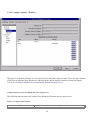
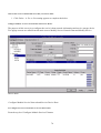
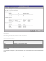
3.5 Configuring and Using the TurboHA Management Console .................................................................60
3.5.1 Configure Module ............................................................................................................................61
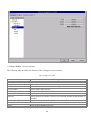
3.5.2 Status Module ..................................................................................................................................71
3.5.3 Service Control Module...................................................................................................................73
4 Service Configuration and Administration ...............................................................................................74
4.1 Configuring a Service .............................................................................................................................74
4.1.1 Gathering Service Information ........................................................................................................75
4.1.2 Creating Service Scripts...................................................................................................................77
4.1.3 Configuring Service Disk Storage ...................................................................................................77
4.1.4 Verifying Application Software and Service Scripts.......................................................................78
4.1.5 Setting Up an Oracle Service...........................................................................................................78
4.1.6 Setting Up a MySQL Service ..........................................................................................................84
4.1.7 Setting Up an DB2 Service ..............................................................................................................88
4.1.8 Setting Up an Apache Service .........................................................................................................91
4.2 Displaying a Service Configuration........................................................................................................96
4.3 Disabling a Service .................................................................................................................................97
4.4 Enabling a Service ..................................................................................................................................98
4.5 Modifying a Service................................................................................................................................98
4.6 Relocating a Service ...............................................................................................................................99
4.7 Deleting a Service ...................................................................................................................................99
4.8 Handling Services in an Error State......................................................................................................100
4.9 Application Agent Checking for Services ............................................................................................101
4.9.1 Application Agents provided with TurboHA ................................................................................101
4.9.2 Application Agent Configuration ..................................................................................................101
4.9.3 Application Agent Checking Summary .........................................................................................103
4.10 Application Agent API .......................................................................................................................103
5 Cluster Administration..............................................................................................................................103
5.1 Displaying Cluster and Service Status..................................................................................................104
5.2 Starting and Stopping the Cluster Software..........................................................................................107
5.3 Modifying the Cluster Configuration....................................................................................................107
5.4 Backing Up and Restoring the Cluster Database..................................................................................108
5.5 Modifying Cluster Event Logging ........................................................................................................108
5.6 Updating the Cluster Software..............................................................................................................109
5.7 Reloading the Cluster Database ............................................................................................................110
3
5.8 Changing the Cluster Name ..................................................................................................................110
5.9 Reinitializing the Cluster ......................................................................................................................110
5.10 Removing a Cluster Member ..............................................................................................................111
5.11 Diagnosing and Correcting Problems in a Cluster..............................................................................112
5.12 Graphical Administration and Monitoring..........................................................................................115
5.12.1 Directions for running TurboHA Management Console on the cluster system...........................116
5.12.2 Directions for running TurboHA Management Console from a remote system..........................116
A Supplementary Hardware Information ..................................................................................................117
A.1 Setting Up a Cyclades Terminal Server...............................................................................................117
A.1.1 Setting Up the Router IP Address .................................................................................................118
A.1.2 Setting Up the Network and Terminal Port Parameters................................................................119
A.1.3 Configuring Turbolinux to Send Console Messages to the Console Port.....................................121
A.1.4 Connecting to the Console Port ....................................................................................................122
A.2 Setting Up an RPS-10 Power Switch ...................................................................................................123
A.3 SCSI Bus Configuration Requirements ...............................................................................................124
A.3.1 SCSI Bus Termination ..................................................................................................................125
A.3.2 SCSI Bus Length...........................................................................................................................126
A.3.3 SCSI Identification Numbers ........................................................................................................127
B Supplementary Software Information ....................................................................................................128
B.1 Cluster Communication Mechanisms ..................................................................................................128
B.2 Cluster Daemons ..................................................................................................................................129
B.3 Failover and Recovery Scenarios.........................................................................................................130
B.3.1 System Hang..................................................................................................................................130
B.3.2 System Panic .................................................................................................................................131
B.3.3 Inaccessible Quorum Partitions.....................................................................................................131
B.3.4 Total Network Connection Failure................................................................................................132
B.3.5 Remote Power Switch Connection Failure ...................................................................................133
B.3.6 Quorum Daemon Failure...............................................................................................................133
B.3.7 Heartbeat Daemon Failure ............................................................................................................134
B.3.8 Power Daemon Failure..................................................................................................................134
B.3.9 Service Manager Daemon Failure.................................................................................................134
B.3.10 Service Check Daemon Error......................................................................................................134
B.4 Cluster Database Fields........................................................................................................................134
B.5 Tuning Oracle Services ........................................................................................................................136
B.6 Raw I/O Programming Example ..........................................................................................................137
B.7 Using TurboHA 6 with Turbolinux Cluster Server..............................................................................138
4
Preface
Registration
TurboHA 6 comes with a serial number in the box which must be entered on the Turbolinux WWW site to
obtain a license file. Please go to the TurboHA 6 product page
(http://www.turbolinux.com.cn/products/turboha) to obtain this product license file.
Licensing
TurboHA 6 requires that each of the two server nodes contain a license. The license is obtained from the
Turbolinux TurboHA web site (http://www.turbolinux.com.cn/products/turboha) by selecting Product
Registration.
You will need to enter the unique registration number that is on the registration card in the box. After you
obtain the license file from the WWW site registration, put it on both cluster systems in /etc/opt/cluster/lic .
Support
For free support, please refer to the registration card in TurboHA 6 box. For an additional fee TurboHA 6
customers can obtain consulting services to assist in installation and hardware certification and even the
development of custom application agents. Please contact your sales representative for more information.
New and Changed Features
Here is an overview of new and changed features in TurboHA 6.
•
Detection of more failures
TurboHA 6 detects a larger number of system failures which increases the level of reliability
provided by the failover cluster. Previously some of these errors might not have been detected,
resulting in an interruption of service without failover recovery.
System Failure - hardware error
System Panic - system software error
Inaccessible Storage - storage error
Network Partition - network error
Cluster Daemon Failure - cluster software error
Service Failure - service application error
5
•
Application Agent Checking
TurboHA 6 provides a method of checking whether a particular service
is functioning by using Application Agents. The Application Agents
are used to periodically check whether a service is functioning. If the
service is not functioning a failover will be triggered and the service
will be resumed on the other node. TurboHA 6 provides a whole set of
Application Agents for common services and even a Generic Agent that
can be used for services that do not have their own Application Agent.
Also refer to the section titled "Application Agent API".
•
Application Agent API
The Application Agent API defines an interface between Application Agents
or service check programs and the TurboHA service checking daemon.
By following this API documented in this manual, you can write a custom Application Agent for
your service.
A custom Application Agent can provide more precise service checking
and possibly faster failover for your application.
•
Failover with safe data protection
Before performing a failover in order to insure data integrity of the
shared storage it is important that the failed cluster system can not
write to the shared storage. TurboHA 6 automatically makes use of a
feature supported in most shared storage devices called SCSI reservation
to ensure the failed cluster system is blocked from writing to the shared
storage. It is strongly recommended that your shared storage support this
feature. This manual provides instructions for how to determine
whether your shared storage supports the SCSI reservation command.
•
Graphical Management Tool
Turbolinux TurboHA 6 improves the manageability of failover clustering
by providing a graphical management tool based on standard X Window
System programming. The graphical management tool provides both
configuration change and status monitoring. The Graphical Management
tool is complemented by a more powerful command line configuration
and monitoring utility.
•
Improved journal file system support
TurboHA 6 supports working with journal file systems such as Reiser and
Ext3. These journal filesystems are ideal for use with TurboHA 6, because
they reduce failover time by eliminating the need for a time-consuming
file system check as is the case with the Ext2 file system. Journal
file systems only require the contents of their journal or log to be
recovered when the filesystem is mounted. TurboHA 6 automatically
recognizes when a journal file system is used for shared storage,
skips the unneeded fsck, and immediately mounts the filesystem for
recovery of the filesystem journal.
6
1 Introduction
TurboHA 6 provides data integrity and the ability to maintain application availability in the event of a
failure. Using redundant hardware, shared disk storage, power management, and robust cluster
communication and application failover mechanisms, a cluster can meet the needs of the enterprise market.
Especially suitable for database applications and World Wide Web (Web) servers with dynamic content, a
cluster can also be used in conjunction with other Linux availability efforts, such as Turbolinux Cluster
Server, to deploy a highly available e-commerce site that has complete data integrity and application
availability, in addition to load balancing capabilities.
1.1 Cluster Overview
To set up a cluster, you connect the cluster systems (often referred to as member systems) to the cluster
hardware, install the TurboHA 6 software on both systems, and configure the systems into the cluster
environment. The foundation of a cluster is an advanced host membership algorithm. This algorithm ensures
that the cluster maintains complete data integrity at all times by using the following methods of inter-node
communication:
•
Quorum disk partitions on shared disk storage to hold system status
•
Ethernet and serial connections between the cluster systems for heartbeat channels
To make an application and data highly available in a cluster, you configure a cluster service, which is a
discrete group of service properties and resources, such as an application and shared disk storage. A service
can be assigned an IP address to provide transparent client access to the service. For example, you can set up
a cluster service that provides clients with access to highly-available database application data.
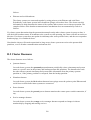
Both cluster systems can run any service and access the service data on shared disk storage. However, each
service can run on only one cluster system at a time, in order to maintain data integrity. You can set up an
active-active configuration in which both cluster systems run different services, or a hot-standby
configuration in which a primary cluster system runs all the services, and a backup cluster system takes over
only if the primary system fails.
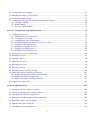
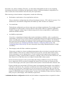
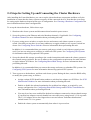
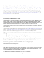
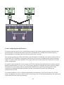
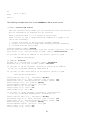
The following figure shows a cluster in an active-active configuration.
7
TurboHA 6 Cluster
If a hardware or software failure occurs, the cluster will automatically restart the failed system's services on
the functional cluster system. This service failover capability ensures that no data is lost, and there is little
disruption to users. When the failed system recovers, the cluster can re-balance the services across the two
systems.
In addition, a cluster administrator can cleanly stop the services running on a cluster system, and then restart
them on the other system. This service relocation capability enables you to maintain application and data
availability when a cluster system requires maintenance.
1.2 Cluster Features
A cluster includes the following features:
•
No-single-point-of-failure hardware configuration
You can set up a cluster that includes a dual-controller RAID array, multiple network and serial
communication channels, and redundant uninterruptible power supply (UPS) systems to ensure that
no single failure results in application down time or loss of data.
Alternately, you can set up a low-cost cluster that provides less availability than a no-single-point-offailure cluster. For example, you can set up a cluster with JBOD ("just a bunch of disks") storage and
only a single heartbeat channel.
8
Note that you cannot use host-based, adapter-based, or software RAID in a cluster, because these
products usually do not properly coordinate multisystem access to shared storage.
•
Service configuration framework
A cluster enables you to easily configure individual services to make data and applications highly
available. To create a service, you specify the resources used in the service and properties for the
service, including the service name, application start and stop script, disk partitions, mount points,
and the cluster system on which you prefer to run the service. After you add a service, the cluster
enters the information into the cluster database on shared storage, where it can be accessed by both
cluster systems.
The cluster provides an easy-to-use framework for database applications. For example, a database
service serves highly-available data to a database application. The application running on a cluster
system provides network access to database client systems, such as Web servers. If the service fails
over to another cluster system, the application can still access the shared database data. A networkaccessible database service is usually assigned an IP address, which is failed over along with the
service to maintain transparent access for clients.
The cluster service framework can be easily extended to other applications, such as mail and print
applications.
•
Data integrity assurance
To ensure data integrity, only one cluster system can run a service and access service data at one
time. Using power switches in the cluster configuration enable each cluster system to power-cycle
the other cluster system before restarting its services during the failover process. This prevents the
two systems from accessing the same data and corrupting it. Although not required, you can use
power switches to guarantee data integrity under all failure conditions.
•
Cluster administration user interface
A user interface simplifies cluster administration and enables you to easily create, start, and stop
services, and monitor the cluster. The interface has both a command-line format and a graphical
format.
•
Multiple cluster communication methods
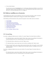
To monitor the health of the other cluster system, each cluster system monitors the health of the
remote power switch, if any, and issues heartbeat pings over network and serial channels to monitor
the health of the other cluster system. In addition, each cluster system periodically writes a
timestamp and cluster state information to two quorum partitions located on shared disk storage.
System state information includes whether the system is an active cluster member. Service state
information includes whether the service is running and which cluster system is running the service.
Each cluster system checks to ensure that the other system's status is up to date.
To ensure correct cluster operation, if a system is unable to write to both quorum partitions at startup
time, it will not be allowed to join the cluster. In addition, if a cluster system is not updating its
9
timestamp, and if heartbeats to the system fail, the cluster system will be removed from the cluster.
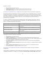
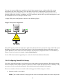
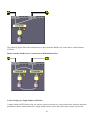
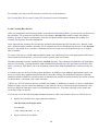
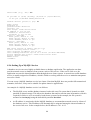
The following figure shows how systems communicate in a cluster configuration.
Cluster Communication Mechanisms
•
Service failover capability
If a hardware or software failure occurs, the cluster will take the appropriate action to maintain
application availability and data integrity. For example, if a cluster system completely fails, the other
cluster system will restart its services. Services already running on this system are not disrupted.
When the failed system reboots and is able to write to the quorum partitions, it can rejoin the cluster
and run services. Depending on how you configured the services, the cluster can re-balance the
services across the two cluster systems.
10
•
Manual service relocation capability
In addition to automatic service failover, a cluster enables administrators to cleanly stop services on
one cluster system and restart them on the other system. This enables administrators to perform
maintenance on a cluster system, while providing application and data availability.
•
Event logging facility
To ensure that problems are detected and resolved before they affect service availability, the cluster
daemons log messages by using the conventional Linux syslog subsystem. You can customize the
severity level of the messages that are logged.
2 Hardware Installation and Operating System
Configuration
To set up the hardware configuration and install the Linux distribution, follow these steps:
1. Choose a cluster hardware configuration that meets the needs of your applications and users.
2. Set up and connect the cluster systems and the optional console switch and network switch or hub.
3. Install and configure Turbolinux on the cluster systems.
4. Set up the remaining cluster hardware components and connect them to the cluster systems.
After setting up the hardware configuration and installing the Linux distribution, you can install the cluster
software.
2.1 Choosing a Hardware Configuration
TurboHA 6 allows you to use commodity hardware to set up a cluster configuration that will meet the
performance, availability, and data integrity needs of your applications and users. Cluster hardware ranges
from low-cost minimum configurations that include only the components required for cluster operation, to
high-end configurations that include redundant heartbeat channels, hardware RAID, and power switches.
Regardless of your configuration, you should always use high-quality hardware in a cluster, because
hardware malfunction is the primary cause of system down time.
Although all cluster configurations provide availability, some configurations protect against every single
point of failure. In addition, all cluster configurations provide data integrity, but some configurations protect
11
data under every failure condition. Therefore, you must fully understand the needs of your computing
environment and also the availability and data integrity features of different hardware configurations, in
order to choose the cluster hardware that will meet your requirements.
When choosing a cluster hardware configuration, consider the following:
•
Performance requirements of your applications and users
Choose a hardware configuration that will provide adequate memory, CPU, and I/O resources. You
should also be sure that the configuration can handle any future increases in workload.
•
Cost restrictions
The hardware configuration you choose must meet your budget requirements. For example, systems
with multiple I/O ports usually cost more than low-end systems with less expansion capabilities.
TurbHA 6 supports a whole range of shared storage devices from a single disk to a multi-ported,
stand-alone RAID controller.
•
Availability requirements
If you have a computing environment that requires the highest availability, such as a production
environment, you can set up a cluster hardware configuration that protects against all single points of
failure, including disk, storage interconnect, heartbeat channel, and power failures. Environments
that can tolerate an interruption in availability, such as development environments, may not require
as much protection. See Configuring Heartbeat Channels, Configuring UPS Systems, and
Configuring Shared Disk Storage for more information about using redundant hardware for high
availability.
•
Data integrity under all failure conditions requirement
Using power switches in a cluster configuration guarantees that service data is protected under every
failure condition. These devices enable a cluster system to power cycle the other cluster system
before restarting its services during failover. Power switches protect against data corruption if an
unresponsive ("hung") system becomes responsive ("unhung") after its services have failed over, and
then issues I/O to a disk that is also receiving I/O from the other cluster system.
SCSI reservation can also be used to protect data under failure conditions as long as the storage
device supports the SCSI reservation command. By using SCSI reservation one system prevents
access to the storage by the other system until the other system is rebooted and enters a known state.
If power switches are not used and SCSI reservation is not supported data integrity is provided by a
"soft shoot" mechanism. The "soft shoot" mechanism relies on the failing system to to respond to a
message over the network. If notification is not received over the network, then fail-over does not
occur. By supporting no power switches and even no SCSI reservation support TurboHA 6 provides
support for all different types of shared storage. You have the flexibility to choose the best solution to
meet your price, data integrity, and availability requirements.
A minimum hardware configuration includes only the hardware components that are required for cluster
12
operation, as follows:
•
•
•
Two servers to run cluster services
Ethernet connection for a heartbeat channel and client network access
Shared disk storage for the cluster quorum partitions and service data
See Example of a Minimum Cluster Configuration for an example of this type of hardware configuration.
The minimum hardware configuration is the most cost-effective cluster configuration; however, it includes
multiple points of failure. For example, if a shared disk fails, any cluster service that uses the disk will be
unavailable. In addition, the minimum configuration does not include power switches, which protect against
data corruption under all failure conditions. Therefore, only development environments should use a
minimum cluster configuration.
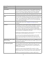
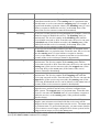
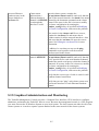
To improve availability and protect against component failure, and to guarantee data integrity under all
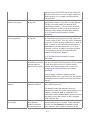
failure conditions, you can expand the minimum configuration. The following table shows how you can
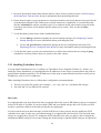
improve availability and guarantee data integrity:
To protect against:
Disk failure
Storage interconnect failure
You can use:
Hardware RAID to replicate data across multiple disks.
RAID array with multiple SCSI buses or Fibre Channel
interconnects.
RAID controller failure
Dual RAID controllers to provide redundant access to disk
data.
Heartbeat channel failure
Point-to-point Ethernet or serial connection between the
cluster systems.
Power source failure
Redundant uninterruptible power supply (UPS) systems.
Data corruption under all failure conditions Power switches or SCSI reservation command
A no-single-point-of-failure hardware configuration that guarantees data integrity under all failure
conditions can include the following components:
•
•
•
•
•
•
•
Two servers to run cluster services
Ethernet connection between each system for a heartbeat channel and client network access
Dual-controller RAID array to replicate quorum partitions and service data. Should support SCSI
reservation command to eliminate the need for power switches.
Two power switches to enable each cluster system to power-cycle the other system during the
failover process
Point-to-point Ethernet connection between the cluster systems for a redundant Ethernet heartbeat
channel
Point-to-point serial connection between the cluster systems for a serial heartbeat channel
Two UPS systems for a highly-available source of power
See Example of a No-Single-Point-Of-Failure Configuration for an example of this type of hardware
configuration.
Cluster hardware configurations can also include other optional hardware components that are common in a
computing environment. For example, you can include a network switch or network hub, which enables
13
you to connect the cluster systems to a network, and a console switch, which facilitates the management of
multiple systems and eliminates the need for separate monitors, mouses, and keyboards for each cluster
system.
One type of console switch is a terminal server, which enables you to connect to serial consoles and manage
many systems from one remote location. As a low-cost alternative, you can use a KVM (keyboard, video,
and mouse) switch, which enables multiple systems to share one keyboard, monitor, and mouse. A KVM is
suitable for configurations in which you access a graphical user interface (GUI) to perform system
management tasks.
When choosing a cluster system, be sure that it provides the PCI slots, network slots, and serial ports that the
hardware configuration requires. For example, a no-single-point-of-failure configuration requires multiple
serial and Ethernet ports. Ideally, choose cluster systems that have at least two serial ports. See Installing the
Basic System Hardware for more information.
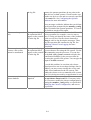
2.1.1 Cluster Hardware Table
Use the following table to identify the hardware components required for your cluster configuration. In some
cases, the table lists specific products that have been tested in a cluster, although a cluster is expected to
work with other products.
Cluster System Hardware
Hardware
Quantity
Description
Required
Cluster system
Two
TurboHA 6 supports IA-32 hardware platforms. Each Yes
cluster system must provide enough PCI slots,
network slots, and serial ports for the cluster hardware
configuration. Because disk devices must have the
same name on each cluster system, it is recommended
that the systems have identical I/O subsystems. In
addition, it is recommended that each system have
450 Mhz CPU speed and 256 MB of memory. See
Installing the Basic System Hardware for more
information.
Power Switch Hardware
Hardware
Quantity
Description
Required
Power switch
Two
Power switches enable each cluster system to power- No.
cycle the other cluster system. A recommended power Recommende
switch is the RPS-10 (model M/HD in the US, and
d for data
model M/EC in Europe), which is available from
integrity if
14
Null modem cable
Two
Mounting bracket
One
www.wti.com/rps-10.htm. See Configuring Power
shared storage
Switches for information about using power switches does not
in a cluster.
support SCSI
reservation.
Null modem cables connect a serial port on a cluster Only if using
system to an power switch. This serial connection
power
enables each cluster system to power-cycle the other switches
system. Some power switches may require different
cables.
Some power switches support rack mount
Only for rack
configurations.
mounting
power
switches
Shared Disk Storage Hardware
Hardware
Quantity
External disk storage One
enclosure
Description
Required
For production environments, it is recommended that Yes. SCSI
you use single-initiator SCSI buses or single-initiator reservation
support is
Fibre Channel interconnects to connect the cluster
systems to a single or dual-controller RAID array. To recommended
as simplest
use single-initiator buses or interconnects, a RAID
controller must have multiple host ports and provide failover data
simultaneous access to all the logical units on the host integrity
solution.
ports. If a logical unit can fail over from one
controller to the other, the process must be transparent
to the operating system.
A recommended SCSI RAID array that provides
simultaneous access to all the logical units on the host
ports is the Winchester Systems FlashDisk RAID
Disk Array, which is available from
www.winsys.com.
A recommended Fibre Channel RAID controller that
provides simultaneous access to all the logical units
on the host ports is the CMD CRD-7220. Integrated
RAID arrays based on the CMD CRD-7220 are
available from Synetex, at www.synetexinc.com.
The shared storage should support the SCSI
reservation command. If the shared storage does not
support SCSI reservation then the use of power
switches is recommended. If the storage does not
support the SCSI reservation command and power
switches are not used, the fail-over cluster will still
function and use a Soft Shoot failover mechanism.
15
But in order to ensure data integrity, fail-over may not
occur in all cases that it would if SCSI reservation or
power switches are used. In the section on hardware
setup a description is provided of how to determine if
the storage supports the SCSI reservation command.
For development environments, you can use a multiinitiator SCSI bus or multi-initiator Fibre Channel
interconnect to connect the cluster systems to a JBOD
storage enclosure, a single-port RAID array, or a
RAID controller that does not provide access to all the
shared logical units from the ports on the storage
enclosure.
You cannot use host-based, adapter-based, or software
RAID products in a cluster, because these products
usually do not properly coordinate multi-system
access to shared storage.
Host bus adapter
Two
See Configuring Shared Disk Storage for more
information.
To connect to shared disk storage, you must install
either a parallel SCSI or a Fibre Channel host bus
adapter in a PCI slot in each cluster system.
For parallel SCSI, use a low voltage differential
(LVD) host bus adapter. Adapters have either HD68
or VHDCI connectors. If you want hot plugging
support, you must be able to disable the host bus
adapter's onboard termination. Recommended parallel
SCSI host bus adapters include the following:
Adaptec 2940U2W, 29160, 29160LP, 39160, and
3950U2
Adaptec AIC-7896 on the Intel L440GX+
motherboard
Qlogic QLA1080 and QLA12160
Tekram Ultra2 DC-390U2W
LSI Logic SYM22915
A recommended Fibre Channel host bus adapter is the
Qlogic QLA2200.
See Host Bus Adapter Features and Configuration
Requirements and Adaptec Host Bus Adapter
Requirement for device features and configuration
information.
16
Yes
SCSI cable
Two
External SCSI LVD
active terminator
Two
SCSI terminator
Two
Fibre Channel hub or One or two
switch
Fibre Channel cable
Two to six
SCSI cables with 68 pins connect each host bus
Only for
adapter to a storage enclosure port. Cables have either parallel SCSI
HD68 or VHDCI connectors.
configurations
For hot plugging support, connect an external LVD Only for
parallel SCSI
active terminator to a host bus adapter that has
configurations
disabled internal termination. This enables you to
that require
disconnect the terminator from the adapter without
affecting bus operation. Terminators have either
external
HD68 or VHDCI connectors.
termination
for hot
Recommended external pass-through terminators with plugging
HD68 connectors can be obtained from Technical
Cable Concepts, Inc., 350 Lear Avenue, Costa Mesa,
California, 92626 (714-835-1081), or
www.techcable.com. The part description and number
is TERM SSM/F LVD/SE Ext Beige, 396868LVD/SE.
For a RAID storage enclosure that uses "out" ports
Only for
(such as FlashDisk RAID Disk Array) and is
parallel SCSI
connected to single-initiator SCSI buses, connect
configurations
terminators to the "out" ports in order to terminate the and only if
buses.
necessary for
termination
A Fibre Channel hub or switch is required, unless you Only for some
have a storage enclosure with two ports, and the host Fibre Channel
bus adapters in the cluster systems can be connected configurations
directly to different ports.
A Fibre Channel cable connects a host bus adapter to Only for Fibre
a storage enclosure port, a Fibre Channel hub, or a
Channel
Fibre Channel switch. If a hub or switch is used,
configurations
additional cables are needed to connect the hub or
switch to the storage adapter ports.
Network Hardware
Hardware
Quantity
Description
Network interface
One for each
network
connection
Each network connection requires a network interface Yes
installed in a cluster system. See Tulip Network
Driver Requirement for information about using this
driver in a cluster.
A network switch or hub enables you to connect
No
multiple systems to a network.
A conventional network cable, such as a cable with an Yes
RJ45 connector, connects each network interface to a
network switch or a network hub.
Network switch or hub One
Network cable
One for each
network
interface
Required
17
Point-To-Point Ethernet Heartbeat Channel Hardware
Hardware
Quantity
Description
Required
Network interface
Two for each
channel
Each Ethernet heartbeat channel requires a network
interface installed in both cluster systems.
No
Network crossover
cable
One for each
channel
A network crossover cable connects a network
interface on one cluster system to a network interface
on the other cluster system, creating an Ethernet
heartbeat channel.
Only for a
redundant
Ethernet
heartbeat
channel
Point-To-Point Serial Heartbeat Channel Hardware
Hardware
Quantity
Description
Required
Serial card
Two for each Each serial heartbeat channel requires a serial port on No
serial channel both cluster systems. To expand your serial port
capacity, you can use multi-port serial PCI cards.
Recommended multi-port cards include the following:
Vision Systems VScom 200H PCI card, which
provides you with two serial ports and is
available from www.vscom.de (see VScom
Multiport Serial Card Configuration for more
information)
Null modem cable
One for each
channel
Cyclades-4YoPCI+ card, which provides you
with four serial ports and is available from
www.cyclades.com
A null modem cable connects a serial port on one
cluster system to a corresponding serial port on the
other cluster system, creating a serial heartbeat
channel.
Only for serial
heartbeat
channel
Console Switch Hardware
Hardware
Quantity
Description
Required
Terminal server
One
A terminal server enables you to manage many
systems from one remote location. Recommended
terminal servers include the following:
No
Cyclades terminal server, which is available from
18
www.cyclades.com
RJ45 to DB9 crossover Two
cable
Network cable
One
KVM
One
NetReach Model CMS-16, which is available
from Western Telematic, Inc. at
www.wti.com/cms.htm
RJ45 to DB9 crossover cables connect a serial port on
each cluster system to a Cyclades terminal server.
Other types of terminal servers may require different
cables.
A network cable connects a terminal server to a
network switch or hub.
A KVM enables multiple systems to share one
keyboard, monitor, and mouse. A recommended KVM
is the Cybex Switchview, which is available from
www.cybex.com. Cables for connecting systems to
the switch depend on the type of KVM.
Only for
terminal
server
Only for
terminal
server
No
UPS System Hardware
Hardware
Quantity
Description
Required
UPS system
One or two
Uninterruptible power supply (UPS) systems provide
a highly-available source of power. Ideally, connect
the power cables for the shared storage enclosure and
both power switches to redundant UPS systems. In
addition, a UPS system must be able to provide
voltage for an adequate period of time.
Strongly
recommended
for
availability
A recommended UPS system is the APC Smart-UPS
1000VA/670W, which is available from
www.apc.com.
2.1.2 Example of a Minimum Cluster Configuration
The hardware components described in the following table can be used to set up a minimum cluster
configuration that uses a multi-initiator SCSI bus and supports hot plugging. This configuration does not
guarantee data integrity under all failure conditions, because it does not include power switches. Note that
this is a sample configuration; you may be able to set up a minimum configuration using other hardware.
Minimum Cluster Hardware Configuration Example
19
Two servers
Each cluster system includes the following hardware:
Network interface for client access and an Ethernet heartbeat channel
One Adaptec 2940U2W SCSI adapter (termination disabled) for the
shared storage connection
Two network cables with
RJ45 connectors
Network cables connect a network interface on each cluster system to the
network for client access and Ethernet heartbeats.
JBOD storage enclosure
The storage enclosure's internal termination is disabled. It is assumed that
this storage supports SCSI reservation which will be used to provide data
integrity after fail-over.
External pass-through LVD active terminators connected to each host bus
adapter provide external SCSI bus termination for hot plugging support.
Two pass-through LVD
active terminators
HD68 cables connect each terminator to a port on the storage enclosure,
creating a multi-initiator SCSI bus.
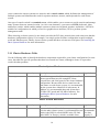
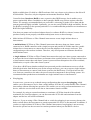
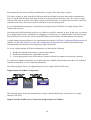
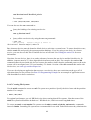
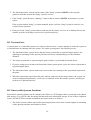
The following figure shows a minimum cluster hardware configuration that includes the hardware described
in the previous table and a multi-initiator SCSI bus, and also supports hot plugging. A "T" enclosed by a
circle indicates internal (onboard) or external SCSI bus termination. A slash through the "T" indicates that
termination has been disabled.
Two HD68 SCSI cables
Minimum Cluster Hardware Configuration With Hot Plugging
20
2.1.3 Example of a No-Single-Point-Of-Failure Configuration
The components described in the following table can be used to set up a no-single-point-of-failure cluster
configuration that includes two single-initiator SCSI buses and power switches to guarantee data integrity
under all failure conditions. Note that this is a sample configuration; you may be able to set up a no-singlepoint-of-failure configuration using other hardware.
No-Single-Point-Of-Failure Configuration Example
Two servers
Each cluster system includes the following hardware:
Two network interfaces for:
Point-to-point Ethernet heartbeat channel
Client network access and Ethernet heartbeat connection
Three serial ports for:
Point-to-point serial heartbeat channel
Remote power switch connection
Connection to the terminal server
One Tekram Ultra2 DC-390U2W adapter (termination enabled) for
the shared disk storage connection
A network switch enables you to connect multiple systems to a network.
One network switch
One Cyclades terminal server A terminal server enables you to manage remote systems from a central
location.
Network cables connect the terminal server and a network interface on
Three network cables
each cluster system to the network switch.
Two RJ45 to DB9 crossover RJ45 to DB9 crossover cables connect a serial port on each cluster system
to the Cyclades terminal server.
cables
One network crossover cable A network crossover cable connects a network interface on one cluster
system to a network interface on the other system, creating a point-to-point
Ethernet heartbeat channel.
Two RPS-10 power switches Power switches enable each cluster system to power-cycle the other
system before restarting its services. The power cable for each cluster
system is connected to its own power switch.
Null modem cables connect a serial port on each cluster system to the
Three null modem cables
power switch that provides power to the other cluster system. This
connection enables each cluster system to power-cycle the other system.
A null modem cable connects a serial port on one cluster system to a
corresponding serial port on the other system, creating a point-to-point
serial heartbeat channel.
21
FlashDisk RAID Disk Array Dual RAID controllers protect against disk and controller failure. The
RAID controllers provide simultaneous access to all the logical units on
with dual controllers
the host ports.
HD68 cables connect each host bus adapter to a RAID enclosure "in" port,
Two HD68 SCSI cables
creating two single-initiator SCSI buses.
Terminators connected to each "out" port on the RAID enclosure terminate
Two terminators
both single-initiator SCSI buses.
UPS systems provide a highly-available source of power. The power
Redundant UPS Systems
cables for the power switches and the RAID enclosure are connected to
two UPS systems.
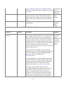
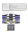
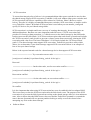
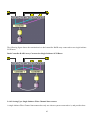
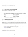
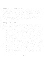
The following figure shows an example of a no-single-point-of-failure hardware configuration that includes
the hardware described in the previous table, two single-initiator SCSI buses, and power switches to
guarantee data integrity under all error conditions.
No-Single-Point-Of-Failure Configuration Example
22
2.2 Steps for Setting Up the Cluster Systems
After you identify the cluster hardware components, as described in Choosing a Hardware Configuration,
you must set up the basic cluster system hardware and connect the systems to the optional console switch and
network switch or hub. Follow these steps:
1. In both cluster systems, install the required network adapters, serial cards, and host bus adapters. See
Installing the Basic System Hardware for more information about performing this task.
2. Set up the optional console switch and connect it to each cluster system. See Setting Up a Console
Switch for more information about performing this task.
If you are not using a console switch, connect each system to a console terminal.
3. Set up the optional network switch or hub and use conventional network cables to connect it to the
cluster systems and the terminal server (if applicable). See Setting Up a Network Switch or Hub for
more information about performing this task.
If you are not using a network switch or hub, use conventional network cables to connect each system
and the terminal server (if applicable) to a network.
After performing the previous tasks, you can install the Linux distribution, as described in Steps for
Installing and Configuring the Linux Distribution.
2.2.1 Installing the Basic System Hardware
Cluster systems must provide the CPU processing power and memory required by your applications. It is
recommended that each system have 450 Mhz CPU speed and 256 MB of memory.
In addition, cluster systems must be able to accommodate the SCSI adapters, network interfaces, and serial
ports that your hardware configuration requires. Systems have a limited number of preinstalled serial and
network ports and PCI expansion slots. The following table will help you determine how much capacity your
cluster systems require:
Cluster Hardware Component
Remote power switch connection
(optional)
SCSI bus to shared disk storage
Serial Ports
One
Network Slots
PCI slots
One for each
bus
Network connection for client access and
One for each network
Ethernet heartbeat
connection
Point-to-point Ethernet heartbeat channel
One for each channel
(optional)
Point-to-point serial heartbeat channel
One for each channel
(optional)
Terminal server connection (optional)
One
23
Most systems come with at least one serial port. Ideally, choose systems that have at least two serial ports. If
your system has a graphics display capability, you can use the serial console port for a serial heartbeat
channel or a power switch connection. To expand your serial port capacity, you can use multi-port serial PCI
cards.
In addition, you must be sure that local system disks will not be on the same SCSI bus as the shared disks.
For example, you can use two-channel SCSI adapters, such as the Adaptec 3950-series cards, and put the
internal devices on one channel and the shared disks on the other channel. You can also use multiple SCSI
cards.
See the system documentation supplied by the vendor for detailed installation information. See
Supplementary Hardware Information for hardware-specific information about using host bus adapters,
multiport serial cards, and Tulip network drivers in a cluster.
The following figure shows the bulkhead of a sample cluster system and the external cable connections for a
typical cluster configuration.
Typical Cluster System External Cabling
24
2.2.2 Setting Up a Console Switch
Although a console switch is not required for cluster operation, you can use one to facilitate cluster system
management and eliminate the need for separate monitors, mouses, and keyboards for each cluster system.
There are several types of console switches.
For example, a terminal server enables you to connect to serial consoles and manage many systems from a
remote location. For a low-cost alternative, you can use a KVM (keyboard, video, and mouse) switch, which
enables multiple systems to share one keyboard, monitor, and mouse. A KVM switch is suitable for
configurations in which you access a graphical user interface (GUI) to perform system management tasks.
Set up the console switch according to the documentation provided by the vendor, unless this manual
provides cluster-specific installation guidelines that supersede the vendor instructions.
After you set up the console switch, connect it to each cluster system.
2.2.3 Setting Up a Network Switch or Hub
Although a network switch or hub is not required for cluster operation, you may want to use one to facilitate
cluster and client system network operations.
Set up a network switch or hub according to the documentation provided by the vendor.
After you set up the network switch or hub, connect it to each cluster system by using conventional network
cables. If you are using a terminal server, use a network cable to connect it to the network switch or hub.
2.3 Steps for Installing and Configuring the Linux Distribution
After you set up the basic system hardware, install the Linux distribution on both cluster systems and ensure
that they recognize the connected devices. Follow these steps:
1. Install a Linux distribution on both cluster systems, following the kernel requirements and guidelines
described in Installing a Linux Distribution.
2. Reboot the cluster systems.
3. If you are using a terminal server, configure Linux to send console messages to the console port.
If you are using a Cyclades terminal server, see Configuring Linux to Send Console Messages to the
Console Port for more information on performing this task.
4. Edit the /etc/hosts file on each cluster system and include the IP addresses used in the cluster. See
Editing the /etc/hosts File for more information about performing this task.
25
5. Decrease the alternate kernel boot timeout limit to reduce cluster system boot time. See Decreasing
the Kernel Boot Timeout Limit for more information about performing this task.
6. Ensure that no login (or getty) programs are associated with the serial ports that are being used for the
serial heartbeat channel or the remote power switch connection, if applicable. To perform this task,
edit the /etc/inittab file and use a number sign (#) to comment out the entries that correspond to the
serial ports used for the serial channel and the remote power switch. Then, invoke the init q
command.
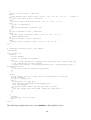
7. Verify that both systems detect all the installed hardware:
•
Use the dmesg command to display the console startup messages. See Displaying Console
Startup Messages for more information about performing this task.
•
Use the cat /proc/devices command to display the devices configured in the kernel. See
Displaying Devices Configured in the Kernel for more information about performing this task.
1. Verify that the cluster systems can communicate over all the network interfaces by using the ping
command to send test packets from one system to the other system.
2.3.1 Installing Turbolinux Server
You can install Turbolinux Server 6.5 software or Turbolinux Server Simplified Chinese 6.1. Before you
install the Linux distribution, you should gather the IP addresses for the cluster systems and for the point-topoint Ethernet heartbeat interfaces The IP addresses for the point-to-point Ethernet interfaces can be private
IP addresses, such as 10.0.0.x addresses.
When installing Turbolinux Server, follow these configuration recommendations:
•
•
Do not put system file systems (for example, /, /usr, /tmp, and /var ) on shared disk storage.
Put /tmp and /var on different file systems.
Boot order
It is important that your boot disk be the first recognized disk in the system. IDE disks are always recognized
before SCSI disks as /dev/hda. If your boot disk is IDE and your shared storage disk is SCSI, then you will
not have a problem with boot order and can skip the next paragraph.
If your boot disk and your shared storage are both SCSI devices, then you may need to modify the SCSI
controller boot order to make sure your shared storage is recognized after the boot disk. The boot disk must
always be recognized as /dev/sda. To change the SCSI controller boot order you may be able to change the
motherboard BIOS setting PCI scan order, change the shared storage controller BIOS setting to be ignored as
26
a boot device, or change the order of plug-in boards in your motherboard PCI slots.
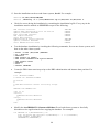
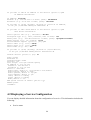
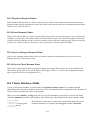
2.3.2 Editing the /etc/hosts File
The /etc/hosts file contains the IP address-to-hostname translation table. On each cluster system, the file must
contain entries for the following:
•
•
IP addresses and associated host names used by both cluster systems.
IP addresses and associated host names used by the point-to-point Ethernet heartbeat connections
(these can be private IP addresses).
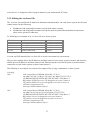
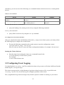
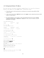
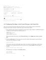
To following is an example of an /etc/hosts file on a cluster system:
127.0.0.1
193.186.1.81
10.0.0.1
193.186.1.82
10.0.0.2
localhost.localdomain
cluster2.linux.com
ecluster2.linux.com
cluster3.linux.com
ecluster3.linux.com
localhost
cluster2
ecluster2
cluster3
ecluster3
You can use DNS instead of the /etc/hosts file to resolve host names on your network.
The previous example shows the IP addresses and host names for two cluster systems (cluster2 and cluster3),
and the private IP addresses and host names for the Ethernet interface used for the point-to-point heartbeat
connection on each cluster system (ecluster2 and ecluster3).
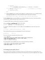
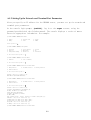
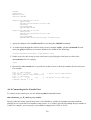
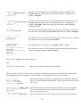
The following is an example of a portion of the output of the ifconfig command on a cluster system:
# ifconfig
eth0
eth1
Link encap:Ethernet HWaddr 00:00:BC:11:76:93
inet addr:192.186.1.81 Bcast:192.186.1.245 Mask:255.255.255.0
UP BROADCAST RUNNING MULTICAST MTU:1500 Metric:1
RX packets:65508254 errors:225 dropped:0 overruns:2 frame:0
TX packets:40364135 errors:0 dropped:0 overruns:0 carrier:0
collisions:0 txqueuelen:100
Interrupt:19 Base address:0xfce0
Link encap:Ethernet HWaddr 00:00:BC:11:76:92
inet addr:10.0.0.1 Bcast:10.0.0.245 Mask:255.255.255.0
UP BROADCAST RUNNING MULTICAST MTU:1500 Metric:1
RX packets:0 errors:0 dropped:0 overruns:0 frame:0
TX packets:0 errors:0 dropped:0 overruns:0 carrier:0
collisions:0 txqueuelen:100
Interrupt:18 Base address:0xfcc0
27
The previous example shows two network interfaces on a cluster system, eth0 (network interface for the
cluster system) and eth1 (network interface for the point-to-point heartbeat connection).
Edit Root $PATH Variable: It is recommended on new or existing Turbolinux Server installations that you
edit the root $PATH variable to add /opt/cluster/bin to your .bashrc $PATH.
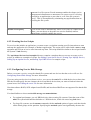
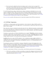
2.3.3 Displaying Console Startup Messages
Use the dmesg command to display the console startup messages. See the dmesg(8) manpage for more
information.
The following example of dmesg command output shows that a serial expansion card was recognized during
startup:
May 22 14:02:10 storage3 kernel: Cyclades driver 2.3.2.5 2000/01/19 14:35:33
May 22 14:02:10 storage3 kernel: built May 8 2000 12:40:12
May 22 14:02:10 storage3 kernel: Cyclom-Y/PCI #1: 0xd0002000-0xd0005fff, IRQ9,
4 channels starting from port 0.
The following example of dmesg command output shows that two external SCSI buses and nine disks were
detected on the system:
May 22 14:02:10 storage3 kernel: scsi0: Adaptec AHA274x/284x/294x (EISA/VLB/PCI-Fast SCSI)
5.1.28/3.2.4
May 22 14:02:10 storage3 kernel:
May 22 14:02:10 storage3 kernel: scsi1: Adaptec AHA274x/284x/294x (EISA/VLB/PCI-Fast SCSI)
5.1.28/3.2.4
May 22 14:02:10 storage3 kernel:
May 22 14:02:10 storage3 kernel: scsi: 2 hosts.
May 22 14:02:11 storage3 kernel: Vendor: SEAGATE Model: ST39236LW Rev: 0004
May 22 14:02:11 storage3 kernel: Detected scsi disk sda at scsi0, channel 0, id 0, lun 0
May 22 14:02:11 storage3 kernel: Vendor: SEAGATE Model: ST318203LC Rev: 0001
May 22 14:02:11 storage3 kernel: Detected scsi disk sdb at scsi1, channel 0, id 0, lun 0
May 22 14:02:11 storage3 kernel: Vendor: SEAGATE Model: ST318203LC Rev: 0001
28
May 22 14:02:11 storage3 kernel: Detected scsi disk sdc at scsi1, channel 0, id 1, lun 0
May 22 14:02:11 storage3 kernel: Vendor: SEAGATE Model: ST318203LC Rev: 0001
May 22 14:02:11 storage3 kernel: Detected scsi disk sdd at scsi1, channel 0, id 2, lun 0
May 22 14:02:11 storage3 kernel: Vendor: SEAGATE Model: ST318203LC Rev: 0001
May 22 14:02:11 storage3 kernel: Detected scsi disk sde at scsi1, channel 0, id 3, lun 0
May 22 14:02:11 storage3 kernel: Vendor: SEAGATE Model: ST318203LC Rev: 0001
May 22 14:02:11 storage3 kernel: Detected scsi disk sdf at scsi1, channel 0, id 8, lun 0
May 22 14:02:11 storage3 kernel: Vendor: SEAGATE Model: ST318203LC Rev: 0001
May 22 14:02:11 storage3 kernel: Detected scsi disk sdg at scsi1, channel 0, id 9, lun 0
May 22 14:02:11 storage3 kernel: Vendor: SEAGATE Model: ST318203LC Rev: 0001
May 22 14:02:11 storage3 kernel: Detected scsi disk sdh at scsi1, channel 0, id 10, lun 0
May 22 14:02:11 storage3 kernel: Vendor: SEAGATE Model: ST318203LC Rev: 0001
May 22 14:02:11 storage3 kernel: Detected scsi disk sdi at scsi1, channel 0, id 11, lun 0
May 22 14:02:11 storage3 kernel: Vendor: Dell Model: 8 BAY U2W CU Rev: 0205
May 22 14:02:11 storage3 kernel: Type: Processor ANSI SCSI revision: 03
May 22 14:02:11 storage3 kernel: scsi1: channel 0 target 15 lun 1 request sense failed, performing reset.
May 22 14:02:11 storage3 kernel: SCSI bus is being reset for host 1 channel 0.
May 22 14:02:11 storage3 kernel: scsi: detected 9 SCSI disks total.
The following example of dmesg command output shows that a quad Ethernet card was detected on the
system:
May 22 14:02:11 storage3 kernel: 3c59x.c:v0.99H 11/17/98 Donald Becker
http://cesdis.gsfc.nasa.gov/linux/drivers/vortex.html
May 22 14:02:11 storage3 kernel: tulip.c:v0.91g-ppc 7/16/99 [email protected]
May 22 14:02:11 storage3 kernel: eth0: Digital DS21140 Tulip rev 34 at 0x9800, 00:00:BC:11:76:93, IRQ 5.
May 22 14:02:12 storage3 kernel: eth1: Digital DS21140 Tulip rev 34 at 0x9400, 00:00:BC:11:76:92, IRQ 9.
29
May 22 14:02:12 storage3 kernel: eth2: Digital DS21140 Tulip rev 34 at 0x9000, 00:00:BC:11:76:91, IRQ
11.
May 22 14:02:12 storage3 kernel: eth3: Digital DS21140 Tulip rev 34 at 0x8800, 00:00:BC:11:76:90, IRQ
10.
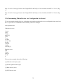
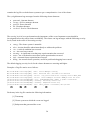
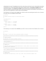
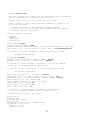
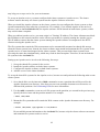
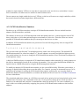
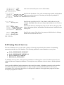
2.3.4 Determining Which Devices Are Configured in the Kernel
To be sure that the installed devices, including serial and network interfaces, are configured in the kernel, use
the cat /proc/devices command on each cluster system. For example:
# cat /proc/devices
Character devices:
1 mem
2 pty
3 ttyp
4 ttyS [1]
5 cua
7 vcs
10 misc
19 ttyC [2]
20 cub
128 ptm
136 pts
162 raw [3]
Block devices:
2 fd
3 ide0
8 sd [4]
65 sd
#
The previous example shows the following:
[1] Onboard serial ports (ttyS)
[2] Serial expansion card (ttyC)
[3] Raw devices (raw)
[4] SCSI devices (sd)
30
2.4 Steps for Setting Up and Connecting the Cluster Hardware
After installing the Linux distribution, you can set up the cluster hardware components and then verify the
installation to ensure that the cluster systems recognize all the connected devices. Note that the exact steps
for setting up the hardware depend on the type of configuration. See Choosing a Hardware Configuration for
more information about cluster configurations.
To set up the cluster hardware, follow these steps:
1. Shut down the cluster systems and disconnect them from their power source.
2. Set up the point-to-point Ethernet and serial heartbeat channels, if applicable. See Configuring
Heartbeat Channels for more information about performing this task.
3. If you are using power switches, set up the devices and connect each cluster system to a power
switch. Note that you may have to set rotary addresses or toggle switches to use a power switch in a
cluster. See Configuring Power Switches for more information about performing this task.
In addition, it is recommended that you connect each power switch (or each cluster system's power
cord if you are not using power switches) to a different UPS system. See Configuring UPS Systems
for information about using optional UPS systems.
4. Set up the shared disk storage according to the vendor instructions and connect the cluster systems to
the external storage enclosure. Be sure to adhere to the configuration requirements for multi-initiator
or single-initiator SCSI buses. See Configuring Shared Disk Storage for more information about
performing this task.
In addition, it is recommended that you connect the storage enclosure to redundant UPS systems. See
Configuring UPS Systems for more information about using optional UPS systems.
5. Turn on power to the hardware, and boot each cluster system. During the boot, enter the BIOS utility
to modify the system setup, as follows:
•
Assign a unique SCSI identification number to each host bus adapter on a SCSI bus. See SCSI
Identification Numbers for more information about performing this task.
•
Enable or disable the onboard termination for each host bus adapter, as required by your
storage configuration. See Configuring Shared Disk Storage and SCSI Bus Termination for
more information about performing this task.
•
You may leave bus resets enabled for the host bus adapters connected to cluster shared storage
if your host bus adapters correctly handle bus resets and you are using kernel 2.2.18 or greater.
The 2.2.18 Adaptec driver does support bus resets and current Turbolinux distributions
include kernel 2.2.18 or greater.
•
Enable the cluster system to automatically boot when it is powered on.
31
If you are using Adaptec host bus adapters for shared storage, see Adaptec Host Bus Adapter
Requirement for configuration information.
1. Exit from the BIOS utility, and continue to boot each system. Examine the startup messages to verify
that the Linux kernel has been configured and can recognize the full set of shared disks. You can also
use the dmesg command to display console startup messages. See Displaying Console Startup
Messages for more information about using this command.
2. Verify that the cluster systems can communicate over each point-to-point Ethernet heartbeat
connection by using the ping command to send packets over each network interface.
3. Set up the quorum disk partitions on the shared disk storage. See Configuring the Quorum Partitions
for more information about performing this task.
2.4.1 Configuring Heartbeat Channels
The cluster uses heartbeat channels to determine the state of the cluster systems. For example, if a cluster
system stops updating its timestamp on the quorum partitions, the other cluster system will check the status
of the heartbeat channels to determine if failover should occur.
A cluster must include at least one heartbeat channel. You can use an Ethernet connection for both client
access and a heartbeat channel. However, it is recommended that you set up additional heartbeat channels for
high availability. You can set up redundant Ethernet heartbeat channels, in addition to one or more serial
heartbeat channels.
For example, if you have an Ethernet and a serial heartbeat channel, and the cable for the Ethernet channel is
disconnected, the cluster systems can still check status through the serial heartbeat channel.
To set up a redundant Ethernet heartbeat channel, use a network crossover cable to connect a network
interface on one cluster system to a network interface on the other cluster system.
To set up a serial heartbeat channel, use a null modem cable to connect a serial port on one cluster system to
a serial port on the other cluster system. Be sure to connect corresponding serial ports on the cluster systems;
do not connect to the serial port that will be used for a remote power switch connection.
2.4.2 Configuring Power Switches
Power switches enable a cluster system to power-cycle the other cluster system before restarting its services
as part of the failover process. The ability to remotely disable a system ensures data integrity under any
failure condition. It is recommended that production environments use power switches in the cluster
configuration. Only development environments should use a configuration without power switches.
32
In a cluster configuration that uses power switches, each cluster system's power cable is connected to its own
power switch. In addition, each cluster system is remotely connected to the other cluster system's power
switch, usually through a serial port connection. When failover occurs, a cluster system can use this
connection to power-cycle the other cluster system before restarting its services.
Power switches protect against data corruption if an unresponsive ("hung") system becomes responsive
("unhung") after its services have failed over, and issues I/O to a disk that is also receiving I/O from the other
cluster system. In addition, if a quorum daemon fails on a cluster system, the system is no longer able to
monitor the quorum partitions. If you are not using power switches in the cluster, this error condition may
result in services being run on more than one cluster system, which can cause data corruption.
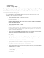
It is recommended that you use power switches or SCSI reservation or in a cluster to ensure data integrity
after a failover. SCSI reservation may be preferable because it does not require additional hardware cost and
installations. Please read the section Configuring Shared Storage regarding SCSI reservation. If you decide to
use power switches, then you must specify the -p option to enable their use.
A cluster system may "hang" for a few seconds if it is swapping or has a high system workload. In this case,
failover does not occur because the other cluster system does not determine that the "hung" system is down.
A cluster system may "hang" indefinitely because of a hardware failure or a kernel error. In this case, the
other cluster will notice that the "hung" system is not updating its timestamp on the quorum partitions, and is
not responding to pings over the heartbeat channels.
If a cluster system determines that a "hung" system is down, and power switches are used in the cluster, the
cluster system will power-cycle the "hung" system before restarting its services. This will cause the "hung"
system to reboot in a clean state, and prevent it from issuing I/O and corrupting service data.
If power switches are not used in cluster, and a cluster system determines that a "hung" system is down, it
will set the status of the failed system to DOWN on the quorum partitions, and then restart the "hung"
system's services. If the "hung" system becomes "unhung," it will notice that its status is DOWN, and initiate
a system reboot. This will minimize the time that both cluster systems may be able to issue I/O to the same
disk, but it does not provide the data integrity guarantee of power switches. If the "hung" system never
becomes responsive, you will have to manually reboot the system.
If you are using power switches, set up the hardware according to the vendor instructions. However, you may
have to perform some cluster-specific tasks to use a power switch in the cluster. See Setting Up an RPS-10
Power Switch for detailed information about using an RPS-10 power switch in a cluster. Note that the
cluster-specific information provided in this document supersedes the vendor information. Also remember to
use the -p option for member_config when installing the cluster software.
After you set up the power switches, perform these tasks to connect them to the cluster systems:
1. Connect the power cable for each cluster system to a power switch.
2. On each cluster system, connect a serial port to the serial port on the power switch that provides
power to the other cluster system. The cable you use for the serial connection depends on the type of
power switch. For example, if you have an RPS-10 power switch, use null modem cables.
33
3. Connect the power cable for each power switch to a power source. It is recommended that you
connect each power switch to a different UPS system. See Configuring UPS Systems for more
information.
After you install the cluster software, but before you start the cluster, test the power switches to ensure that
each cluster system can power-cycle the other system. See Testing the Power Switches for information.
2.4.3 Configuring UPS Systems
Uninterruptible power supply (UPS) systems protect against downtime if a power outage occurs. Although
UPS systems are not required for cluster operation, they are recommended. For the highest availability,
connect the power switches (or the power cords for the cluster systems if you are not using power switches)
and the disk storage subsystem to redundant UPS systems. In addition, each UPS system must be connected
to its own power circuit.
Be sure that each UPS system can provide adequate power to its attached devices. If a power outage occurs, a
UPS system must be able to provide power for an adequate amount of time.
Redundant UPS systems provide a highly-available source of power. If a power outage occurs, the power
load for the cluster devices will be distributed over the UPS systems. If one of the UPS systems fail, the
cluster applications will still be available.
If your disk storage subsystem has two power supplies with separate power cords, set up two UPS systems,
and connect one power switch (or one cluster system's power cord if you are not using power switches) and
one of the storage subsystem's power cords to each UPS system.
A redundant UPS system configuration is shown in the following figure.
Redundant UPS System Configuration
34
You can also connect both power switches (or both cluster systems' power cords) and the disk storage
subsystem to the same UPS system. This is the most cost-effective configuration, and provides some
protection against power failure. However, if a power outage occurs, the single UPS system becomes a
possible single point of failure. In addition, one UPS system may not be able to provide enough power to all
the attached devices for an adequate amount of time.
A single UPS system configuration is shown in the following figure.
Single UPS System Configuration
Many UPS system products include Linux applications that monitor the operational status of the UPS system
through a serial port connection. If the battery power is low, the monitoring software will initiate a clean
system shutdown. If this occurs, the cluster software will be properly stopped, because it is controlled by a
System V run level script (for example, /etc/rc.d/init.d/cluster).
See the UPS documentation supplied by the vendor for detailed installation information.
2.4.4 Configuring Shared Disk Storage
In a cluster, shared disk storage is used to hold service data and two quorum partitions. Because this storage
must be available to both cluster systems, it cannot be located on disks that depend on the availability of any
one system. See the vendor documentation for detailed product and installation information.
There are a number of factors to consider when setting up shared disk storage in a cluster:
•
Hardware RAID versus JBOD
JBOD ("just a bunch of disks") storage provides a low-cost storage solution, but it does not provide
35
highly available data. If a disk in a JBOD enclosure fails, any cluster service that uses the disk will
be unavailable. Therefore, only development environments should use JBOD.
Controller-based hardware RAID is more expensive than JBOD storage, but it enables you to
protect against disk failure. In addition, a dual-controller RAID array protects against controller
failure. It is strongly recommended that you use RAID 1 (mirroring) to make service data and the
quorum partitions highly available. Optionally, you can use parity RAID for high availability. Do not
use RAID 0 (striping) for the quorum partitions. It is recommended that production environments use
RAID for high availability.
Note that you cannot use host-based, adapter-based, or software RAID in a cluster, because these
products usually do not properly coordinate multisystem access to shared storage.
•
Multi-initiator SCSI buses or Fibre Channel interconnects versus single-initiator buses or
interconnects
A multi-initiator SCSI bus or Fibre Channel interconnect has more than one cluster system
connected to it. RAID controllers with a single host port and parallel SCSI disks must use a multiinitiator bus or interconnect to connect the two host bus adapters to the storage enclosure. This
configuration provides no host isolation. Therefore, only development environments should use
multi-initiator buses.
A single-initiator SCSI bus or Fibre Channel interconnect has only one cluster system connected to
it, and provides host isolation and better performance than a multi-initiator bus. Single-initiator buses
or interconnects ensure that each cluster system is protected from disruptions due to the workload,
initialization, or repair of the other cluster system.
If you have a RAID array that has multiple host ports and provides simultaneous access to all the
shared logical units from the host ports on the storage enclosure, you can set up two single-initiator
buses or interconnects to connect each cluster system to the RAID array. If a logical unit can fail
over from one controller to the other, the process must be transparent to the operating system. It is
recommended that production environments use single-initiator buses or interconnects.
•
Hot plugging
In some cases, you can set up a shared storage configuration that supports hot plugging, which
enables you to disconnect a device from a multi-initiator SCSI bus or a multi-initiator Fibre Channel
interconnect without affecting bus operation. This enables you to easily perform maintenance on a
device, while the services that use the bus or interconnect remain available.
For example, by using an external terminator to terminate a SCSI bus instead of the onboard
termination for a host bus adapter, you can disconnect the SCSI cable and terminator from the
adapter and the bus will still be terminated.
However, if you are using a Fibre Channel hub or switch, hot plugging is not necessary because the
hub or switch allows the interconnect to remain operational if a device is disconnected. In addition, if
you have a single-initiator SCSI bus or Fibre Channel interconnect, hot plugging is not necessary
because the private bus does not need to remain operational when you disconnect a device.
36
•
SCSI reservation
To ensure data integrity after a failover it is recommended that either power switches be used or that
the shared storage support SCSI reservation. TurboHA 6 will work without either power switches and
SCSI reservation, but failover capability will be reduced to "Software Shoot" (Refer to section
below). Therefore it is highly recommended that power switches, SCSI reservation, or both be used in
every TurboHA 6 cluster. By default SCSI reservation is used when you run member_config and
specify SG devices for your shared storage disks.
SCSI reservation is a simpler and lower cost way of ensuring data integrity, because it requires no
additional hardware. But there are some important tradeoffs to note. 1) SCSI reservation only
provides I/O fencing or data protection, i.e. it blocks access to the shared storage by the failed node,
but does not reset the failed node. 2) SCSI reservation requires that each cluster system kernel include
the "SCSI reservation" patch in order to prevent a cluster system from erroneously clearing the SCSI
reservation with a bus reset. The latest Turbolinux 2.2.18 kernels include the "SCSI reservation"
patch. 3) The shared storage must support SCSI reservation. TurboHA 6 provides a utility which
allows you to determine if your shared storage supports SCSI reservation. Below is an example of
how to test your shared storage.
Below is the expected normal result for a shared storage device that supports SCSI reservation.
=================== Try reservation on one node ===================
[root@server1 turboha]# /opt/cluster/bin/sg_switch -d /dev/sg0 -s
Reserve6!
=================== On the other node, test for reservation conflict =======
[root@server2 turboha]# /opt/cluster/bin/sg_switch -d /dev/sg0 -c
Reservation conflict!
==================== On the other node, no reservation conflict =====
[root@server2 turboha]# /opt/cluster/bin/sg_switch -d /dev/sg0 -c
No conflict.
It is also important that when using SCSI reservation bus resets be enabled in the bus adapter BIOS.
This is necessary to clear the SCSI reservation after the failed node resets. The purpose of the SCSI
reservation is to prevent the failed system from writing to the shared storage when it is in an unknown
state. After a reboot when the BIOS issues a bus reset and the TurboHA 6 quorumd is re-started the
state is known. Quorumd will use quorum partition locking to safely recover the cluster before
attempting any write to the shared storage.
•
Software Shoot
37
If power switches are not used in the cluster and the shared storage does not support SCSI
reservation, then a fall back fail-over data integrity mechanism is used named Software Shoot. When
the power daemon is instructed to shoot a node, it sends a message to the power daemon on the failed
node to cause a reboot. The failed node will acknowledge the message and immediately reboot itself.
After receiving the acknowledgment the healthy node will fail-over the shared storage and services
from the healthy node.
If the Software Shoot fails, the healthy node will continue trying to shoot the failed node. It will not
fail-over the shared storage and services from the failed node. Software Shoot mode is enabled if you
do not specify SG devices for the shared storage when using member_config, Because the number of
failures that will cause fail-over is reduced it is strongly recommended to use either power switches or
SCSI reservation.
Note that you must carefully follow the configuration guidelines for multi and single-initiator buses and for
hot plugging, in order for the cluster to operate correctly.
You must adhere to the following shared storage requirements:
•
The Linux device name for each shared storage device must be the same on each cluster system. For
example, a device named /dev/sdc on one cluster system must be named /dev/sdc on the other
cluster system. You can usually ensure that devices are named the same by using identical hardware
for both cluster systems.
•
A disk partition can be used by only one cluster service.
•
Do not include any file systems used in a cluster service in the cluster system's local /etc/fstab files,
because the cluster software must control the mounting and unmounting of service file systems.
•
For optimal performance, use a 4 KB block size when creating shared file systems. Note that some of
the mkfs file system build utilities default to a 1 KB block size, which can cause long fsck times. It
is recommended that you use a journaling file system such as the Reiser file system (reiserfs) or
EXT3 file system (ext3) to eliminate fsck time and therefore reduce failover time. The latest
Turbolinux Server releases support both reiserfs and ext3 for use with cluster failover like TurboHA
6.
You must adhere to the following parallel SCSI requirements, if applicable:
•
SCSI buses must be terminated at each end, and must adhere to length and hot plugging restrictions.
•
Devices (disks, host bus adapters, and RAID controllers) on a SCSI bus must have a unique SCSI
identification number.
•
SCSI bus resets must be enabled if SCSI reservation is used.
See SCSI Bus Configuration Requirements for more information.
In addition, it is strongly recommended that you connect the storage enclosure to redundant UPS systems
38
for a highly-available source of power. See Configuring UPS Systems for more information.
See Setting Up a Multi-Initiator SCSI Bus, Setting Up a Single-Initiator SCSI Bus, and Setting Up a SingleInitiator Fibre Channel Interconnect for more information about configuring shared storage.
After you set up the shared disk storage hardware, you can partition the disks and then either create file
systems or raw devices on the partitions. You must create two raw devices for the primary and the backup
quorum partitions. See Configuring the Quorum Partitions, Partitioning Disks, Creating Raw Devices, and
Creating File Systems for more information.
2.4.4.1 Setting Up a Multi-Initiator SCSI Bus
A multi-initiator SCSI bus has more than one cluster system connected to it. If you have JBOD storage, you
must use a multi-initiator SCSI bus to connect the cluster systems to the shared disks in a cluster storage
enclosure. You also must use a multi-initiator bus if you have a RAID controller that does not provide access
to all the shared logical units from host ports on the storage enclosure, or has only one host port.
A multi-initiator bus does not provide host isolation. Therefore, only development environments should use a
multi-initiator bus.
A multi-initiator bus must adhere to the requirements described in SCSI Bus Configuration Requirements. In
addition, see Host Bus Adapter Features and Configuration Requirements for information about terminating
host bus adapters and configuring a multi-initiator bus with and without hot plugging support.
In general, to set up a multi-initiator SCSI bus with a cluster system at each end of the bus, you must do the
following:
•
•
•
Enable the onboard termination for each host bus adapter.
Disable the termination for the storage enclosure, if applicable.
Use the appropriate 68-pin SCSI cable to connect each host bus adapter to the storage enclosure.
To set host bus adapter termination, you usually must enter the system configuration utility during system
boot. To set RAID controller or storage enclosure termination, see the vendor documentation.
The following figure shows a multi-initiator SCSI bus with no hot plugging support.
Multi-Initiator SCSI Bus Configuration
If the onboard termination for a host bus adapter can be disabled, you can configure it for hot plugging. This
allows you to disconnect the adapter from the multi-initiator bus, without affecting bus termination, so you
can perform maintenance while the bus remains operational.
To configure a host bus adapter for hot plugging, you must do the following:
39
•
•
Disable the onboard termination for the host bus adapter.
Connect an external pass-through LVD active terminator to the host bus adapter connector.
You can then use the appropriate 68-pin SCSI cable to connect the LVD terminator to the (unterminated)
storage enclosure.
The following figure shows a multi-initiator SCSI bus with both host bus adapters configured for hot
plugging.
Multi-Initiator SCSI Bus Configuration With Hot Plugging
The following figure shows the termination in a JBOD storage enclosure connected to a multi-initiator SCSI
bus.
JBOD Storage Connected to a Multi-Initiator Bus
The following figure shows the termination in a single-controller RAID array connected to a multi-initiator
SCSI bus.
Single-Controller RAID Array Connected to a Multi-Initiator Bus
40
The following figure shows the termination in a dual-controller RAID array connected to a multi-initiator
SCSI bus.
Dual-Controller RAID Array Connected to a Multi-Initiator Bus
2.4.4.2 Setting Up a Single-Initiator SCSI Bus
A single-initiator SCSI bus has only one cluster system connected to it, and provides host isolation and better
performance than a multi-initiator bus. Single-initiator buses ensure that each cluster system is protected
41
from disruptions due to the workload, initialization, or repair of the other cluster system.
If you have a single or dual-controller RAID array that has multiple host ports and provides simultaneous
access to all the shared logical units from the host ports on the storage enclosure, you can set up two singleinitiator SCSI buses to connect each cluster system to the RAID array. If a logical unit can fail over from one
controller to the other, the process must be transparent to the operating system.
It is recommended that production environments use single-initiator SCSI buses or single-initiator Fibre
Channel interconnects.
Note that some RAID controllers restrict a set of disks to a specific controller or port. In this case, you cannot
set up single-initiator buses. In addition, hot plugging is not necessary in a single-initiator SCSI bus, because
the private bus does not need to remain operational when you disconnect a host bus adapter from the bus.
A single-initiator bus must adhere to the requirements described in SCSI Bus Configuration Requirements. In
addition, see Host Bus Adapter Features and Configuration Requirements for detailed information about
terminating host bus adapters and configuring a single-initiator bus.
To set up a single-initiator SCSI bus configuration, you must do the following:
•
•
•
Enable the onboard termination for each host bus adapter.
Enable the termination for each RAID controller.
Use the appropriate 68-pin SCSI cable to connect each host bus adapter to the storage enclosure.
To set host bus adapter termination, you usually must enter a BIOS utility during system boot. To set RAID
controller termination, see the vendor documentation.
The following figure shows a configuration that uses two single-initiator SCSI buses.
Single-Initiator SCSI Bus Configuration
The following figure shows the termination in a single-controller RAID array connected to two singleinitiator SCSI buses.
Single-Controller RAID Array Connected to Single-Initiator SCSI Buses
42
The following figure shows the termination in a dual-controller RAID array connected to two single-initiator
SCSI buses.
Dual-Controller RAID Array Connected to Single-Initiator SCSI Buses
2.4.4.3 Setting Up a Single-Initiator Fibre Channel Interconnect
A single-initiator Fibre Channel interconnect has only one cluster system connected to it, and provides host
43
isolation and better performance than a multi-initiator bus. Single-initiator interconnects ensure that each
cluster system is protected from disruptions due to the workload, initialization, or repair of the other cluster
system.
It is recommended that production environments use single-initiator SCSI buses or single-initiator Fibre
Channel interconnects.
If you have a RAID array that has multiple host ports, and the RAID array provides simultaneous access to
all the shared logical units from the host ports on the storage enclosure, you can set up two single-initiator
Fibre Channel interconnects to connect each cluster system to the RAID array. If a logical unit can fail over
from one controller to the other, the process must be transparent to the operating system.
The following figure shows a single-controller RAID array with two host ports, and the host bus adapters
connected directly to the RAID controller, without using Fibre Channel hubs or switches.
Single-Controller RAID Array Connected to Single-Initiator Fibre Channel Interconnects
If you have a dual-controller RAID array with two host ports on each controller, you must use a Fibre
Channel hub or switch to connect each host bus adapter to one port on both controllers, as shown in the
following figure.
Dual-Controller RAID Array Connected to Single-Initiator Fibre Channel Interconnects
44
2.4.4.4 Configuring Quorum Partitions
You must create two raw devices on shared disk storage for the primary quorum partition and the backup
quorum partition. Each quorum partition must have a minimum size of 2 MB. The amount of data in a
quorum partition is constant; it does not increase or decrease over time.
The quorum partitions are used to hold cluster state information. Periodically, each cluster system writes its
status (either UP or DOWN), a timestamp, and the state of its services. In addition, the quorum partitions
contain a version of the cluster database. This ensures that each cluster system has a common view of the
cluster configuration.
To monitor cluster health, the cluster systems periodically read state information from the primary quorum
partition and determine if it is up to date. If the primary partition is corrupted, the cluster systems read the
information from the backup quorum partition and simultaneously repair the primary partition. Data
consistency is maintained through checksums and any inconsistencies between the partitions are
automatically corrected.
If a system is unable to write to both quorum partitions at startup time, it will not be allowed to join the
cluster. In addition, if an active cluster system can no longer write to both quorum partitions, the system will
remove itself from the cluster by rebooting.
45
You must adhere to the following quorum partition requirements:
•
Both quorum partitions must have a minimum size of 2 MB.
•
Quorum partitions must be raw devices. They cannot contain file systems.
•
The quorum partitions must be located on the same shared SCSI bus or the same RAID controller.
This prevents a situation in which each cluster system has access to only one of the partitions.
•
Quorum partitions can be used only for cluster state and configuration information.
The following are recommended guidelines for configuring the quorum partitions:
•
For compatibility with future releases, it is recommended that you make the size of each quorum
partition 10 MB.
•
It is strongly recommended that you set up a RAID subsystem for shared storage, and use RAID 1
(mirroring) to make the logical unit that contains the quorum partitions highly available. Optionally,
you can use parity RAID for high availability. Do not use RAID 0 (striping) for the quorum
partitions.
Otherwise, put both quorum partitions on the same disk.
•
Do not put the quorum partitions on a disk that contains heavily-accessed service data. If possible,
locate the quorum partitions on disks that contain service data that is lightly accessed.
See Partitioning Disks and Creating Raw Devices for more information about setting up the quorum
partitions.
See Editing the rawio File for information about editing the rawio file to bind the raw character devices to
the block devices each time the cluster systems boot.
2.4.4.5 Partitioning Disks
After you set up the shared disk storage hardware, you must partition the disks so they can be used in the
cluster. You can then create file systems or raw devices on the partitions. For example, you must create two
raw devices for the quorum partitions, using the guidelines described in Configuring Quorum Partitions.
Invoke the interactive fdisk command to modify a disk partition table and divide the disk into partitions. Use
the p command to display the current partition table. Use the n command to create a new partition.
The following example shows how to use the fdisk command to partition a disk:
1. Invoke the interactive fdisk command, specifying an available shared disk device. At the prompt,
46
specify the p command to display the current partition table. For example:
# fdisk /dev/sde
Command (m for help): p
Disk /dev/sde: 255 heads, 63 sectors, 2213 cylinders
Units = cylinders of 16065 * 512 bytes
Device
Boot
/dev/sde1
/dev/sde2
Start
1
263
End
262
288
Blocks
2104483+
208845
Id
83
83
System
Linux
Linux
2. Determine the number of the next available partition, and specify the n command to add the partition.
If there are already three partitions on the disk, specify e for extended partition or p to create a
primary partition. For example:
Command (m for help): n
Command action
e
extended
p
primary partition (1-4)
3. Specify the partition number that you want. For example:
Partition number (1-4): 3
4. Press the Enter key or specify the next available cylinder. For example:
First cylinder (289-2213, default 289): 289
5. Specify the partition size that is required. For example:
Last cylinder or +size or +sizeM or +sizeK (289-2213, default 2213): +2000M
Note that large partitions will increase the cluster service failover time if a file system on the partition
must be checked with fsck. Quorum partitions must be at least 2 MB, although 10 MB is
recommended.
6. Specify the w command to write the new partition table to disk. For example:
Command (m for help): w
The partition table has been altered!
Calling ioctl() to re-read partition table.
WARNING: If you have created or modified any DOS 6.x
partitions, please see the fdisk manual page for additional
information.
Syncing disks.
7. If you added a partition while both cluster systems are powered on and connected to the shared
storage, you must reboot the other cluster system in order for it to recognize the new partition.
After you partition a disk, you can format it for use in the cluster. You must create raw devices for the
quorum partitions. You can also format the remainder of the shared disks as needed by the cluster services.
47
For example, you can create file systems or raw devices on the partitions.
See Creating Raw Devices and Creating File Systems for more information.
2.4.4.6 Creating Raw Devices
After you partition the shared storage disks, as described in Partitioning Disks, you can create raw devices on
the partitions. File systems are block devices (for example, /dev/sda1) that cache recently-used data in
memory in order to improve performance. Raw devices do not utilize system memory for caching. See
Creating File Systems for more information.
Linux supports raw character devices that are not hard-coded against specific block devices. Instead, Linux
uses a character major number (currently 162) to implement a series of unbound raw devices in the /dev/raw
directory. Any block device can have a character raw device front-end, even if the block device is loaded
later at runtime.
To create a raw device, use the raw command to bind a raw character device to the appropriate block device.
Once bound to a block device, a raw device can be opened, read, and written.
The raw command is usually installed in the /usr/bin directory. The command is included in all Turbolinux
Servers. If necessary, you can obtain the raw command from metalab.unc.edu:/pub/linux/system/misc/utillinux-2.10k.tar.gz. Note that 2.10k is the minimum version of the raw command; later versions can also be
used.
You must create raw devices for the quorum partitions. In addition, some database applications require raw
devices, because these applications perform their own buffer caching for performance purposes. Quorum
partitions cannot contain file systems because if state data was cached in system memory, the cluster systems
would not have a consistent view of the state data.
[1]There are 255 raw character devices available for binding, in addition to a master raw device (with minor
number 0) that is used to control the bindings on the other raw devices. Note that the permissions for a raw
device are different from those on the corresponding block device. You must explicitly set the mode and
ownership of the raw device.
You can use one of the following raw command formats to bind a raw character device to a block device:
•
Specify the block device's major and minor numbers:
raw /dev/raw/rawN major minor
For example:
# raw /dev/raw/raw1
•
8
33
Specify a block device name:
48
raw /dev/raw/rawN /dev/block_device
For example:
# raw /dev/raw/raw1 /dev/sdc1
You can also use the raw command to:
• Query the binding of an existing raw device:
raw -q /dev/raw/rawN
•
Query all the raw devices by using the raw -aq command:
# raw -aq
/dev/raw/raw1
bound to major 8, minor 17
/dev/raw/raw2 bound to major 8, minor 18
Raw character devices must be bound to block devices each time a system boots. To ensure that this occurs,
edit the rawio file and specify the quorum partition bindings. If you are using a raw device in a cluster
service, you can also use this file to bind the devices at boot time. See Editing the rawio File for more
information.
Note that, for raw devices, there is no cache coherency between the raw device and the block device. In
addition, requests must be 512-byte aligned both in memory and on disk. For example, the standard dd
command cannot be used with raw devices because the memory buffer that the command passes to the write
system call is not aligned on a 512-byte boundary. To obtain a version of the dd command that works with
raw devices, see www.sgi.com/developers/oss.
If you are developing an application that accesses a raw device, there are restrictions on the type of I/O
operations that you can perform. See Raw I/O Programming Example for an example of application source
code that adheres to these restrictions.
2.4.4.7 Creating File Systems
Use the mkfs command to create an ext2 file system on a partition. Specify the drive letter and the partition
number. For example:
# mkfs /dev/sde3
For optimal performance, use a 4 KB block size when creating shared file systems. Note that some of the
mkfs file system build utilities default to a 1 KB block size, which can cause long fsck times.
To create an ext3 or reiserfs file systems use the mkfs.ext3 and mkfs.reiserfs commands
instead of mkfs. Journaling file systems are recommended for use with TurboHA because they eliminate the
49
need for fsck and therefore reduce failover time. Turbolinux Servers support both ext3 and reiserfs
file systems.
3 Cluster Software Installation and Configuration
After you install and configure the cluster hardware, you must install the TurboHA cluster software and
initialize the cluster systems
•
•
•
•
•
Installing and Initializing the Cluster Software
Configuring Event Logging
Running the member_config Utility
Using the cluadmin Utility
Configuring and Using the TurboHA Management Console
3.1 Installing and Initializing the Cluster Software
Turbolinux provides the TurboHA cluster software in rpm package format. There are six files necessary to
install TurboHA:
• installer
• turboha-6.0-4.i386.rpm
• pdksh-5.2.14-2.i386.rpm
• raw-2.10-1.i386.rpm
• lsof-4.45-1.i386.rpm
• sg_utils-0.93-1.i386.rpm
By default, the software installation procedure installs the cluster software in the /opt/cluster directory.
Before installing TurboHA, be sure that you have sufficient disk space to accommodate the files. The files
only require approximately 10 MB of disk space.
3.1.1 To Install TurboHA Using the Installer Script
From the command line at a terminal window or console:
1.
2.
3.
4.
Login as root .
Change to the directory that contains all four files required for TurboHA.
Execute the script with the command ./installer .
Now perform this procedure on the other cluster member.
50
You must do these procedures on BOTH member systems.
3.1.2 To Install TurboHA without the Installer Script
From the command line at a terminal window or console:
Login as root .
1. Change to the directory that contains the three required TurboHA 6 rpm packages. Then implement
the three following commands:
rpm -Uvh
pdksh-5.2.14-2.i386.rpm
rpm -Uvh
raw-2.10-1.i386.rpm
rpm -Uvh
lsof-4.45-1.i386.rpm
rpm -Uvh
sg_utils-0.93-1.i386.rpm
rpm -Uvh
turboha-6.0-4.i386.rpm
1. Now perform this routine on the other cluster member.
3.1.3 To Initialize the Cluster Software
Follow these steps to initialize the cluster software. From the command line at a terminal window or console:
Edit the rawio file and specify the raw device special files and character devices for the primary and
backup quorum partitions. You also must set the mode for the raw devices so that all users have read
permission.
See To Edit the rawio File for more information on these topics.
1. Execute the rawio script with the command /etc/rc.d/init.d/rawio .
2. Configure event logging so that cluster messages are logged to a separate file. See Configuring Event
Logging for more information.
You must do steps 1, 2 and 3 on BOTH member systems
.
51
1. Run the /opt/cluster/bin/member_config utility on one cluster system and specify cluster-specific
information at the prompts. If you are using power switches add the option -p to the member_config
command line. If you are using SCSI reservation or Software Shoot do not use the -p option. Refer to
Configuring Power Switches and Configuring Shared Storage for more information. To determine
whether your shared storage supports SCSI Reservation refer to the section Configuring Shared
Storage. If your shared storage does support SCSI Reservation then enter SG devices when prompted.
If your shared storage does not support SCSI reservation, then do not enter SG device information. It
is strongly recommended that you use either power switches or SCSI reservation. If you do not
specify the member_config -p option and do not enter member_config SG devices, then the Software
Shoot failover mechanism will be used which results in failover for fewer failure scenarios. Refer to
Configuring Shared Storage for more information about the Software Shoot data integrity feature.
To Edit the rawio File
As part of the cluster software installation procedure, you must edit the rawio file on each cluster system and
specify the raw device special files and character devices for the primary and backup quorum partitions. The
rawio file is located in the /etc/init.d directory (for example, /etc/rc.d/init.d/rawio) . You also must set the
mode for the raw devices so that all users have read permission. This maps the block devices to the character
devices for the quorum partitions when each cluster system boots An example of a rawio file is as follows:
#!/bin/bash
# rawio
Map block devices to raw character devices.
# description: rawio mapping
# chkconfig: 2345 98 01
#
# Bind raw devices to block devices.
# Tailor to match the device special files matching your disk configuration.
# Note: Must be world readable for cluster web GUI to be operational.
# If you use SCSI disks, and the module of SCSI is loaded as a kernel module, please uncomment
the following line, to ensure the module will be loaded before cluster daemons starting.
#modprobe scsi_hostadapter
# If you use ext3 partitions, and ext3 is a loadable module, please uncomment the following line.
#modprobe ext3
#raw /dev/raw/raw1 /dev/sdb2
#chmod a+r /dev/raw/raw1
#raw /dev/raw/raw2 /dev/sdb3
#chmod a+r /dev/raw/raw2
52
Alternately, you can use one of the following raw command formats to bind raw devices to existing block
devices:
Table 3.1 raw Command
specify
block-device major and minor
numbers
Bind to an existing block device
format
raw /dev/raw/rawN <major>
<minor>
:raw /dev/raw/rawN
/dev/<block_device>
You can also use the raw command to:
•
example
# raw /dev/raw/raw1 8 33
# raw /dev/raw/raw1
/dev/sdc1
Query the binding of an existing raw device by using the following command:
# raw -q /dev/raw/rawN
•
Query all the raw devices by using the raw -aq command.
To Configure the Second Cluster Member
After you complete the cluster initialization with member_config on one cluster system, you must perform
the following step to configure the second cluster.
•
Execute the following command on the second system to sync the configuration content:
/opt/cluster/bin/clu_config –-init=init_file
Init_file is the raw device to store the cluster configuration database, for example: /dev/raw/raw1.
Starting the Cluster Software
•
Start the cluster by invoking the cluster start command located in the
/etc/init.d directory on both cluster systems.
For example:
# /etc/rc.d/init.d/cluster start
3.2 Configuring Event Logging
You should edit the /etc/syslog . conf file to enable the cluster to log events to a file that is different from the
default log file, /var/log/messages .
The cluster systems use the syslogd daemon to log cluster-related events to a file, as specified in the
/etc/syslog . conf file. You can use the log file to diagnose problems in the cluster.
The syslogd daemon logs cluster messages only from the system on which it is running, so you need to
53
examine the log files on both cluster systems to get a comprehensive view of the cluster.
The syslogd daemon logs messages from the following cluster daemons:
•
•
•
•
•
quorumd - Quorum daemon
svcmgr - Service manager daemon
powerd - Power daemon
hb - Heartbeat daemon
svccheck - Service Check daemon
The severity level of an event determines the importance of the event. Important events should be
investigated before they affect cluster availability. The cluster can log messages with the following severity
levels, listed in the order of decreasing severity:
•
•
•
•
•
•
•
•
emerg - The cluster system is unusable.
alert - Action should be taken immediately to address the problem.
crit - A critical condition has occurred.
err - An error has occurred.
warning - A significant event that may require attention has occurred.
notice - An event that does not affect system operation has occurred.
info - A normal cluster operation has occurred.
debug - An normal cluster operation, useful for problem debugging has occurred.
The default logging severity levels for the cluster daemons are warning and higher.
Examples of log file entries are as follows:
May
May
May
May
Jun
Jun
Jun
Jul
31 20:42:06
31 20:42:06
31 20:49:38
31 20:49:39
01 12:56:51
01 12:34:24
01 12:34:24
27 15:28:40
[1]
clu2
clu2
clu2
clu2
clu2
clu2
clu2
clu2
[2]
svcmgr[992]: <info> Service Manager starting
svcmgr[992]: <info> mount.ksh info: /dev/sda3 is not mounted
clulog[1294]: <notice> stop_service.ksh notice: Stopping service dbase_home
svcmgr[1287]: <notice> Service Manager received a NODE_UP event for stor5
quorumd[1640]: <err> updateMyTimestamp: unable to update status block.
quorumd[1268]: <warning> Initiating cluster stop
quorumd[1268]: <warning> Completed cluster stop
quorumd[390]: <err> shoot_partner: successfully shot partner.
[3]
[4]
[5]
Each entry in the log file contains the following information:
[1] Timestamp
[2] Cluster system on which the event was logged
[3] Subsystem that generated the event
54
[4] Severity level of the event
[5] Description of the event
After you configure the cluster software, you should edit the /etc/syslog . conf file to enable the cluster to log
events to a file that is different from the default log file, /var/log/messages . Using a cluster-specific log file
facilitates cluster monitoring and problem solving. Add the following line to the /etc/syslog . conf file to log
cluster events to both the /var/log/cluster and /var/log/messages files:
#
# Cluster messages coming in on local4 go to /var/log/cluster
#
local4.*
/var/log/cluster
To prevent the duplication of messages and log cluster events only to the /var/log/cluster file, add
local4.none to the following lines in the /etc/syslog . conf file:
# Log anything (except mail) of level info or higher.
# Don't log private authentication messages!
*.info;mail.none;news.none;authpriv.none;local4.none
/var/log/messages
To apply the previous changes, you can reboot the system or invoke the killall -HUP syslogd command. In
addition, you can modify the severity level of the events that are logged by the powerd , quorumd , hb , and
svcmgr daemons. To change a daemon's logging level, invoke the cluadmin utility, and specify the cluster
loglevel command, the name of the daemon, and the severity level.
You can specify the severity level by using the name or the number that corresponds to the severity level.
The values 0 to 7 refer to the following severity levels:
Table 3.2 Severity Levels
Value Severity
0
emerg
1
alert
2
crit
3
err
4
warning
5
notice
6
info
7
debug
The following example enables the quorumd daemon to log messages of all severity levels:
[root@server1 /root]# /opt/cluster/bin/cluadmin
Sat Apr 28 15:08:26 CST 2001
55
You can obtain help by entering help and one of the following commands:
cluster service
clear
help
apropos
exit
cluadmin> cluster loglevel quorumd 7
cluadmin>
3.3 Running the member_config Utility
To initialize the cluster with member_config , you need the following information, which will be entered into
the member fields in the cluster database located in the /etc/opt/cluster/cluster . conf file:
•
•
•
•
•
•
•
Raw device special files for the primary and backup quorum partitions, as specified in the rawio file
For example, /dev/raw/raw1 and /dev/raw/raw2
Cluster system hostnames that are returned by the hostname command
Number of heartbeat connections (channels), both Ethernet and serial
Device special file for each heartbeat serial line connection
For example, /dev/ttyS1
IP hostname associated with each heartbeat Ethernet interface
Device special files for the serial ports to which the power switches are connected
For example, /dev/ttyS0
SG device information if using SCSI Reservation. Refer to Configuring Shared Storage for more
information.
For example, /dev/sg0
See for an example of running the utility and Cluster Configuration File Member Fields for a detailed
description of the cluster configuration file fields. In addition, the
/opt/cluster/dc/services/examples/cluster.conf_members file contains a sample cluster configuration file.
Note that it is only a sample file. Your actual cluster configuration file must be customized for your
configuration.
After you have initialized the cluster, you can add cluster services. See Configuring and Using the TurboHA
Management Console for more information.
Cluster Configuration File Member Fields
After you run the member_config utility, the cluster database in the /etc/opt/cluster/cluster.conf file will
include site-specific information in the fields within the [ members] section.
56
?he following is a description of the cluster member fields:
start member0
Specifies the tty port that is connected to a null model cable for a serial
start chan0
heartbeat channel. For example, the serial_port could be /dev/ttyS1.
device =serial_port
type = serial
end chan0
start chan1
Specifies the network interface for one Ethernet heartbeat channel. The
name = interface_name
interface_name is the host name to which the interface is assigned (for
type = net end
example, storage0 ).
chan1
start chan2
Specifies the network interface for a second Ethernet heartbeat channel.
device = interface_name type = The interface_name is the host name to which the interface is assigned
net
(for example, cstorage0 ). This field can specify the point-to-point
end chan2
dedicated heartbeat network.
id = id
Specifies the identification number (either 0 or 1) for the cluster system
name = system_name
and the name that is returned by the hostname command. For example,
the system_name could be storage0 .
quorumPartitionPrimary =
Specifies the raw device files for the primary and backup quorum
raw_disk
partitions (for example, raw_device could be /dev/raw/raw1 and
quorumPartitionShadow =
/dev/raw/raw2 ).
raw_disk
end member0
Do not manually edit the cluster.conf file. Instead, use the cluadmin utility or the TurboHA Management
Console to modify the file.
3.4 Using the cluadmin Utility
The cluadmin utility provides a command-line user interface that enables you to monitor and manage the
cluster systems and services. For example, you can use the cluadmin utility to perform the following tasks:
•
•
•
•
Add, modify, and delete services
Disable and enable services
Display cluster and service status
Modify cluster daemon event logging
57
You can also use the TurboHA Management Console to configure and monitor cluster systems and services.
See Configuring and Using the TurboHA Management Console for more information.
The cluster uses an advisory lock to prevent the cluster database from being simultaneously modified by
multiple users on either cluster system. You can only modify the database if you hold the advisory lock.
When you invoke the cluadmin utility, the cluster software checks if the lock is already assigned to a user. If
the lock is not already assigned, the cluster software assigns you the lock. When you exit from the cluadmin
utility, you relinquish the lock.
If another user holds the lock, a warning will be displayed indicating that there is already a lock on the
database. The cluster software gives you the option of seizing the lock. If you seize the lock, the previous
holder of the lock can no longer modify the cluster database.
You should seize the lock only if necessary, because uncoordinated simultaneous configuration sessions may
cause unpredictable cluster behavior. In addition, it is recommended that you make only one change to the
cluster database (for example, adding, modifying, or deleting services) at one time. You can specify the
following cluadmin command line options:
-d or --debug
-h, -?, or --help
-n or
--nointeractive
-t or --tcl
Displays extensive diagnostic information.
Displays help about the utility, and then exits.
Bypasses the cluadmin utility's top-level command loop processing. This option is
used for cluadmin debugging purposes.
Adds a Tcl command to the cluadmin utility's top- level command interpreter. To pass
a Tcl command directly to the utility's internal Tcl interpreter, at the cluadmin>
prompt, preface the Tcl command with tcl. This option is used for cluadmin
debugging purposes.
-V or --version
Displays information about the current version of cluadmin .
When you invoke the cluadmin utility without the -n option, the cluadmin> prompt appears. You can then
specify commands and subcommands. The following table describes the commands and subcommands for
the cluadmin utility:
Table 3.3 cluadmin Commands and Subcommands
cluadmin
cluadmin
description
command subcommand
help
none
Displays help for the specified cluadmin command or subcommand. For
example:
cluadmin> help service add
cluster
status
Displays a snapshot of the current cluster status. See To View a Status for
information. For example: cluadmin> cluster status
cluster
monitor
Continuously displays snapshots of the cluster status at five second intervals.
Press the Return or Enter key to stop the display. You can specify the interval option with a numeric argument to display snapshots at the specified
time interval (in seconds). In addition, you can specify the -clear option with
a yes argument to clear the screen after each snapshot display or with a no
58
argument to not clear the screen. See To View a Status for more for
information.
cluster
heartbeat
cluster
loglevel
cluster
name
cluster
service
showname
add
service
modify
service
show state
service
show config
service
disable
service
enable
service
delete
apropos
none
clear
none
exit, quit, q, none
bye
For example:
cluadmin> cluster monitor -clear yes -interval 10
Sets the values for the heartbeat port interval and tko_count. For example:
cluadmin> cluster heartbeat interval 20
Sets the logging for the specified cluster daemon to the specified severity
level. See Configuring Event Logging for information. For example:
cluadmin> cluster loglevel quorumd 7
Sets the name of the cluster to the specified name. The cluster name is
included in the output of the clustat cluster monitoring command and the
TurboHA Management Console. For example:
cluadmin> cluster name dbcluster
Displays the name of your TurboHA cluster configuration.
Adds a cluster service to the cluster database. The command prompts you
for information about service resources and properties. SeeConfigure
Module - Services for information. For example:
cluadmin> service add
Modifies the resources or properties of the specified service. You can
modify any of the information that you specified when the service was
created. See To Modify a Service for information. For example: cluadmin>
service modify dbservice
Displays the current status of all services or the specified service. SeeTo
View a Status for information. For example: cluadmin> service show state
dbservice
Displays the current configuration for the specified service. See To View a
Status for information. For example: cluadmin> service show config
dbservice
Stops the specified service. You must enable a service to make it available
again. See To Delete a Service for information. For example: cluadmin>
service disable dbservice
Starts the specified disabled service. See To Start or Stop a Service for
information. For example:
cluadmin> service enable dbservice
Deletes the specified service from the cluster configuration database. See To
Delete a Service for information. For example: cluadmin> service delete
dbservice
Displays the cluadmin commands that match the specified character string
argument or, if no argument is specified, displays all cluadmin commands.
For example:
cluadmin> apropos service
Clears the screen display. For example:
cluadmin> clear
Exits from cluadmin . For example: cluadmin> exit
59
While using cluadmin utility, you can press the Tab key to help identify cluadmin commands.
•
•
•
•
Pressing the Tab key at the cluadmin> utility displays a list of all the commands.
Entering a letter at the prompt and then pressing the Tab key displays the commands that begin with
the specified letter.
Specifying a command and then pressing the Tab key displays a list of all the subcommands that can
be specified with that command.
In addition, you can display the history of cluadmin commands by pressing the Up arrow or Down
arrow key at the prompt.
3.5 Configuring and Using the TurboHA Management Console
There are three main modules in the TurboHA Management Console: Configure, Status, and Service Control.
60
Top Level Screens of TurboHA Management Console
These modules are used to configure and monitor members and services. The screens contained within these
modules make up the TurboHA Management Console. The modules are accessible by clicking on the tab as
shown in Figure 3.1.
The following table describes the features of the and modules available throughout the TurboHA
Management Console.
Table 3.4 Configuration Screen Features
feature
Configure Module
description
Core administration tool where all cluster and service configuration data can
be viewed and modified.
Status Module
Core monitoring tool where the cluster status can be viewed as a snapshot.
Service Control Module Core service administration tool where all service statuses can be viewed and
changed.
OK Button
Approves the entry or change of data in the Configure Module. Dismisses the
TurboHA Management Console.
Apply Button
Approves the entry or change of data in the Configure Module. The
TurboHA Management Console remains.
Cancel Button
Backs out of entry of data in the Configure Module. Dismisses the TurboHA
Management Console.
3.5.1 Configure Module
3.5.1.1 Configure Module and Cluster Configuration Pane
The TurboHA Management Console defaults to the Configure Module. This is the module where most of the
core administration tools are accessed See Configure Module Element Tree and Configuration Panes. The
left pane of the Configure Module, the Cluster Configuration pane, contains a tree of elements that can be
configured with the TurboHA Management Console. The right pane changes according to the selected
element from the left Cluster Configuration pane.
61
Configure Module Element Tree and Configuration Panes
The right pane contains fields and tables of data for cluster functions. These fields and tables are directly
related to options and data prompts in the cluadmin utility and member_config tools.
Table 3.5 Cluster Configuration Pane Elements
elements
General
Member0
Member1
Services
http (example)
oracle (example)
description
Global fields for all cluster members.
Fields for Member0.
Fields for Member1.
Adds or deletes services.
Example of a service-related field.
Example of a service-related field.
62
3.5.1.2 Configure Module - General
The General element from the Configure Module is used to set global options for a new or existing cluster.
Configuration Module - General Element
The following fields describe the features of the Configuration Module-General Element Screen.
Table 3.6 Configuration Module-General Element Fields
fields
Cluster Name
description
Sets the name of the cluster to the specified name. This is the same
63
functionality as using the following command within the cluadmin utility:
cluadmin> cluster name dbcluster
Heartbeat
Interval
Log Level
Port
KO Count
Sets the heartbeat interval in seconds.
cluadmin> cluster heartbeat interval 0
Sets the logging for the heartbeat daemon to the specified severity level. This
is the same functionality as the cluadmin command:
cluadmin> cluster heartbeat loglevel 5
Sets the port number on which both ends of the heartbeat channel listen for
responses.
cluadmin> cluster heartbeat port 1126
Sets the number of permitted "failures" of the Heartbeat connection.
cluadmin> cluster heartbeat tko_count 3
Daemon
Svcmgr Log Level Sets the logging for the specified svcmgr daemon to the specified severity
level.
cluadmin> cluster loglevel svcmgr 5
Powerd Log Level Sets the logging for the specified powerd daemon to the specified severity
level.
cluadmin> cluster loglevel powerd 5
Quorumd Log
Sets the logging for the specified quorumd daemon to the specified severity
Level
level.
cluadmin> cluster loglevel quorumd 5
To Configure a Cluster
From the Configure Module:
Click on General in the Element Tree.
1. Enter the information required by each field. See Table 3.6 for definitions.
2. Click Apply .
64
3.5.1.3 Configure Module - Members
The purpose of Member Element is to set options for an individual cluster member. There are three features
of this screen: Member Data, Heartbeat Connection Data, and its Modify Heartbeat Connection Popup
Screen, See Configure Member Screen and Modify Heartbeat Popup Screen.
Configure Member Screen and Modify Heartbeat Popup Screen
The following table describes the feature of the Members Elements and its popup screen.
Table 3.7 Configure Member Fields
field
description
65
Member ID
Member Name
Primary Quorum Partition
Shadow Quorum Partition
Heartbeat Connection Data
Type
Name
Device
Unique node number for each member.
Hostname for member.
Device filename for Primary Quorum partition.
Device filename for Shadow Quorum partition.
Heartbeat type: net or serial.
Hostname this heartbeat responds to.
Device filename for serial connections.
To Configure a Member
From the Configure Module-Element screen:
Click on Member0 or Member1 element in the Element Tree.
1. Enter the field values. See Table 3.7 for definitions.
2. Click Apply to keep the field values.
Much of the Member Field Data cannot be modified while your TurboHA 6 cluster is running. These fields
will be grayed out. You can only view their values while the cluster is running.
To Change Heartbeat Connection Data
From the lower part of the Configure Module Element:
Click to highlight the Heartbeat Connection.
1. Click on the Modify button.
The Modify Heartbeat Connection popup screen appears.
1. Enter the changed information.
2. Click OK.
The change is implemented and the popup screen is dismissed. The changed values are shown in the main
Members screen.
To Add a Heartbeat Connection
From the lower part of the Configure Module Element:
66
Click in a blank line to highlight it.
1. Click on that line's Modify button. A blank Modify Heartbeat popup appears.
2. Enter the new information in the fields.
3. Click OK to add the new element.
The new values appear in the Main Members screen.
To Delete a Heartbeat Connection
From the lower part of the Configure Module Element:
Click to highlight the device value.
1. Click on the Modify button.
The Modify Heartbeat popup screen appears.
1. Click Delete, to delete the values in the fields.
2. Click OK to dismiss the popup screen.
The deleted values are removed from the main Members screen.
3.5.1.4 Configure Module - Services
The purpose of the Configure Services screen is to add, delete, or modify a service.
67
Configure Module - Services Screens
The following table describes the features of the Configure Services Screen.
Table 3.8 Configure Services Fields
feature
Add or Delete Services
Delete Button
Add New Service Button
Service Name
Disabled
Preferred Node
Relocate
Service Control Script
Service Check Data
Script
description
Deletes the selected service.
Adds a blank, unnamed service for configuration.
Sets the name of the service.
Sets services as disabled by default.
Sets the preferred member to run the service.
Sets preference to relocate a service to a preferred member if that member is
available.
Script to control start and stop of service.
Script to check health of service.
68
Interval
Timeout
Max Error Count
Service Network Data
IP Address
Netmask
Broadcast
Service Device Data
Device Name
Owner
Group
Mode
Mount Name
Mount Options
Force Unmount
Interval to check services in seconds.
Maximum time to wait for response from script to check service health
before counting an error.
Maximum number of errors before service is relocated.
Alias IP address for the service.
Network mask address for the service.
Network broadcast address.
Device filename for storage devices.
Device file owner.
Device file group.
Octal value permissions for the device.
Main path for device file.
Sets special mount options for the device.
If set to yes, the device is forcefully unmounted when the server is disabled.
To Add a Service
From the top level Configure Module Services Element:
Click on the Add New Service Button. A new unnamed service appears in the Element Tree.
1. Click on the newly created item in the Element Tree.
2. Enter the information in the fields.
3. Click Apply to implement the data.
To Modify a Service
From the top level Configure Module Services Element:
Click on the service in the Element Tree that you want to modify.
1. Enter the field information.
2. Click Apply to implement the data.
To Delete a Service
From the top level Configure Module Services Element:
69
Click on the service in the Element Tree that you want to delete.
1. Click Delete . A Yes or No warning appears to complete the delete.
Configure Module - Service Network Data and Service Device
The purpose of this screen is to configure the service's host network information and service storage device.
Two popup screens are called from the main screen: Modify Service Network Data and Modify Service
Device Data.
Configure Module Service Network and Service Device Data
To Configure Service Network Data or Service Device Data
From the top level Configure Module Services Element:
70
Click to highlight the Service Network or Service Device entry to configure.
or
1. Click in a blank line to add a new item.
2. Click on the Modify button.
The Modify Service Network Data or the Modify Service Device Data popup screen appears.
1. Enter the information in the fields.
2. Click OK to implement the changes and dismiss the popup.
To Delete a Service Network Entry or Service Device Entry
From the top level Configure Services screen:
Click to highlight the Service Network entry or Service Device entry.
1. Click on the Modify button.
The Modify Service Network Data or the Modify Service Device Data popup screen appears.
•
•
Click Delete, to delete the values in the fields.
Click OK to dismiss the popup screen.
The deleted entry is removed from the main screen.
3.5.2 Status Module
The purpose of the Status Module is give a snapshot view of all elements of the cluster.
71
Status Screen
The following table describes the features of the Status Screen.
Table 3.9 Status Screen Features
feature
Name
Date
Member Status
Channel Status
Service Status
Description
Shows the name of the cluster.
Time stamp of snapshot cluster status.
Shows the current status of all members associated with the cluster.
Shows the current status of all heartbeat channels associated with the cluster.
Shows the current status of all services associated with the cluster.
To View a Status
You can update the snapshot of your cluster status by a left-mouse click anywhere within the Status Module
screen.
72
3.5.3 Service Control Module
The purpose of this screen is to view the current status of all configured services and to manually start or stop
a configured service.
Service Control Module
The following table describes the features of the Service Control Screen.
Table 3.10 Service Control Screen Features
feature
Start
Stop
Description
Starts a service.
Stops a service.
73
Service ID
Status
Shows the name of the service.
Shows the running state of the service.
To Start or Stop a Service
From the top level Service control screen:
Click on the Start button to start the service contained in the highlighted line.
•
Click on the Start button again to toggle back-and-forth between start and stopping a service.
4 Service Configuration and Administration
The following sections describe how to set up and administer cluster services:
•
•
•
•
•
•
•
•
Configuring a Service
Displaying a Service Configuration
Disabling a Service
Enabling a Service
Modifying a Service
Relocating a Service
Deleting a Service
Handling Services in an Error State
4.1 Configuring a Service
To configure a service, you must prepare the cluster systems for the service. For example, you must set up
any disk storage or applications used in the services. You can then add information about the service
properties and resources to the cluster database, a copy of which is located in the
/etc/opt/cluster/cluster.conf file. This information is used as parameters to scripts that start and stop the
service.
To configure a service, follow these steps
1. If applicable, create a script that will start and stop the application used in the service. See Creating
Service Scripts for information.
2. Select or write an Application Agent to be used by the svccheck daemon to periodically check the
74
health of the service. The Generic Application Agent can be used for services that do not have their
own agent. See Service Application Agent for more information.
3. Gather information about service resources and properties. See Gathering Service Information for
information.
4. Set up the file systems or raw devices that the service will use. See Configuring Service Disk Storage
for information.
5. Ensure that the application software can run on each cluster system and that the service script, if any,
can start and stop the service application. See Verifying Application Software and Service Scripts for
information.
6. Back up the /etc/opt/cluster/cluster.conf file. See Backing Up and Restoring the Cluster Database
for information.
7. Invoke the cluadmin utility and specify the service add command. You will be prompted for
information about the service resources and properties obtained in step 2. If the service passes the
configuration checks, it will be started on the cluster system on which you are running cluadmin,
unless you choose to keep the service disabled. For example:
cluadmin> service add
For more information about adding a cluster service, see the following:
•
•
•
•
Setting Up an Oracle Service
Setting Up a MySQL Service
Setting Up a DB2 Service
Setting Up an Apache Service
See Cluster Database Fields for a description of the service fields in the database. In addition, the
/opt/cluster/doc/services/examples/cluster.conf_services file contains an example of a service entry from a
cluster configuration file. Note that it is only an example.
4.1.1 Gathering Service Information
Before you create a service, you must gather information about the service resources and properties. When
you add a service to the cluster database, the cluadmin utility prompts you for this information.
In some cases, you can specify multiple resources for a service. For example, you can specify multiple IP
addresses and disk devices.
The service properties and resources that you can specify are described in the following table.
75
Service Property or
Resource
Description
Service name
Each service must have a unique name. A service name can consist of
one to 63 characters and must consist of a combination of letters (either
uppercase or lowercase), integers, underscores, periods, and dashes.
However, a service name must begin with a letter or an underscore.
Specify the cluster system, if any, on which you want the service to run
unless failover has occurred or unless you manually relocate the service.
Preferred member
Preferred member relocation If you enable this policy, the service will automatically relocate to its
preferred member when that system joins the cluster. If you disable this
policy
policy, the service will remain running on the non-preferred member. For
example, if you enable this policy and the failed preferred member for
the service reboots and joins the cluster, the service will automatically
restart on the preferred member.
If applicable, specify the full path name for the script that will be used to
Script location
start and stop the service. See Creating Service Scripts for more
information.
You can assign one or more Internet protocol (IP) addresses to a service.
IP address
This IP address (sometimes called a "floating" IP address) is different
from the IP address associated with the host name Ethernet interface for a
cluster system, because it is automatically relocated along with the
service resources, when failover occurs. If clients use this IP address to
access the service, they do not know which cluster system is running the
service, and failover is transparent to the clients.
Note that cluster members must have network interface cards configured
in the IP subnet of each IP address used in a service.
You can also specify netmask and broadcast addresses for each IP
address. If you do not specify this information, the cluster uses the
netmask and broadcast addresses from the network interconnect in the
subnet.
Disk partition, owner, group, Specify each shared disk partition used in a service. In addition, you can
specify the owner, group, and access mode (for example, 755) for each
and access mode
mount point or raw device.
If you are using a file system, you must specify the type of file system, a
Mount points, file system
mount point, and any mount options. Mount options that you can specify
type, and mount options
are the standard file system mount options that are described in the
mount.8 manpage. If you are using a raw device, you do not have to
specify mount information.
The ext2 file system is the recommended file system for a cluster.
Although you can use a different file system in a cluster, log-based and
other file systems such as reiserfs and ext3 have not been fully tested.
In addition, you must specify whether you want to enable forced
76
unmount for a file system. Forced unmount enables the cluster service
management infrastructure to unmount a file system even if it is being
accessed by an application or user (that is, even if the file system is
"busy"). This is accomplished by terminating any applications that are
accessing the file system.
Disable service policy
If you do not want to automatically start a service after it is added to the
cluster, you can choose to keep the new service disabled, until an
administrator explicitly enables the service.
4.1.2 Creating Service Scripts
For services that include an application, you must create a script that contains specific instructions to start
and stop the application (for example, a database application). The script will be called with a start or stop
argument and will run at service start time and stop time. The script should be similar to the scripts found in
the System V init directory.
The /opt/cluster/doc/services/examples directory contains a template that you can use to create service
scripts, in addition to examples of scripts. See Setting Up an Oracle Service, Setting Up a MySQL Service,
Setting Up an Apache Service, and Setting Up a DB2 Service for sample scripts.
4.1.3 Configuring Service Disk Storage
Before you create a service, set up the shared file systems and raw devices that the service will use. See
Configuring Shared Disk Storage for more information.
If you are using raw devices in a cluster service, you can use the rawio file to bind the devices at boot time.
Edit the file and specify the raw character devices and block devices that you want to bind each time the
system boots. See Editing the rawio File for more information.
Note that software RAID, SCSI adapter-based RAID, and host-based RAID are not supported for shared disk
storage.
You should adhere to these service disk storage recommendations:
•
For optimal performance, use a 4 KB block size when creating file systems. Note that some of the
mkfs file system build utilities default to a 1 KB block size, which can cause long fsck times.
•
For large file systems, use the mount command with the nocheck option to bypass code that checks
all the block groups on the partition. Specifying the nocheck option can significantly decrease the
77
time required to mount a large file system.
4.1.4 Verifying Application Software and Service Scripts
Before you set up a service, install any application that will be used in a service on each system. After you
install the application, verify that the application runs and can access shared disk storage. To prevent data
corruption, do not run the application simultaneously on both systems.
If you are using a script to start and stop the service application, you must install and test the script on both
cluster systems, and verify that it can be used to start and stop the application. See Creating Service Scripts
for information.
4.1.5 Setting Up an Oracle Service
A database service can serve highly-available data to a database application. The application can then
provide network access to database client systems, such as Web servers. If the service fails over, the
application accesses the shared database data through the new cluster system. A network-accessible database
service is usually assigned an IP address, which is failed over along with the service to maintain transparent
access for clients.
This section provides an example of setting up a cluster service for an Oracle database. Although the
variables used in the service scripts depend on the specific Oracle configuration, the example may help you
set up a service for your environment. See Tuning Oracle Services for information about improving service
performance.
In the example that follows:
•
The service includes one IP address for the Oracle clients to use.
•
The service has two mounted file systems, one for the Oracle software (/u01) and the other for the
Oracle database (/u02), which were set up before the service was added.
•
An Oracle administration account with the name oracle was created on both cluster systems before
the service was added.
•
Network access in this example is through Perl DBI proxy.
•
The administration directory is on a shared disk that is used in conjunction with the Oracle service
(for example, /u01/app/oracle/admin/db1).
The Oracle service example uses five scripts that must be placed in /home/oracle and owned by the Oracle
78
administration account. The oracle script is used to start and stop the Oracle service. Specify this script when
you add the service. This script calls the other Oracle example scripts. The startdb and stopdb scripts start
and stop the database. The startdbi and stopdbi scripts start and stop a Web application that has been
written by using Perl scripts and modules and is used to interact with the Oracle database. Note that there are
many ways for an application to interact with an Oracle database.
The following is an example of the oracle script, which is used to start and stop the Oracle service. Note that
the script is run as user oracle, instead of root.
#!/bin/sh
#
# Cluster service script to start/stop oracle
#
cd /home/oracle
case $1 in
'start')
su - oracle
su - oracle
;;
'stop')
su - oracle
su - oracle
;;
esac
-c ./startdbi
-c ./startdb
-c ./stopdb
-c ./stopdbi
The following is an example of the startdb script, which is used to start the Oracle Database Server instance:
#!/bin/sh
#
#
# Script to start the Oracle Database Server instance.
#
###########################################################################
#
# ORACLE_RELEASE
#
# Specifies the Oracle product release.
#
###########################################################################
ORACLE_RELEASE=8.1.6
###########################################################################
#
# ORACLE_SID
#
# Specifies the Oracle system identifier or "sid", which is the name of the
# Oracle Server instance.
#
###########################################################################
export ORACLE_SID=TESTDB
###########################################################################
#
# ORACLE_BASE
#
# Specifies the directory at the top of the Oracle software product and
79
# administrative file structure.
#
###########################################################################
export ORACLE_BASE=/u01/app/oracle
###########################################################################
#
# ORACLE_HOME
#
# Specifies the directory containing the software for a given release.
# The Oracle recommended value is $ORACLE_BASE/product/<release>
#
###########################################################################
export ORACLE_HOME=/u01/app/oracle/product/${ORACLE_RELEASE}
###########################################################################
#
# LD_LIBRARY_PATH
#
# Required when using Oracle products that use shared libraries.
#
###########################################################################
export LD_LIBRARY_PATH=/u01/app/oracle/product/${ORACLE_RELEASE}/lib
###########################################################################
#
# PATH
#
# Verify that the users search path includes $ORCLE_HOME/bin
#
###########################################################################
export PATH=$PATH:/u01/app/oracle/product/${ORACLE_RELEASE}/bin
###########################################################################
#
# This does the actual work.
#
# The oracle server manager is used to start the Oracle Server instance
# based on the initSID.ora initialization parameters file specified.
#
###########################################################################
/u01/app/oracle/product/${ORACLE_RELEASE}/bin/svrmgrl << EOF
spool /home/oracle/startdb.log
connect internal;
startup pfile = /u01/app/oracle/admin/db1/pfile/initTESTDB.ora open;
spool off
EOF
exit 0
The following is an example of the stopdb script, which is used to stop the Oracle Database Server instance:
#!/bin/sh
#
#
# Script to STOP the Oracle Database Server instance.
#
###########################################################################
#
80
# ORACLE_RELEASE
#
# Specifies the Oracle product release.
#
###########################################################################
ORACLE_RELEASE=8.1.6
###########################################################################
#
# ORACLE_SID
#
# Specifies the Oracle system identifier or "sid", which is the name of the
# Oracle Server instance.
#
###########################################################################
export ORACLE_SID=TESTDB
###########################################################################
#
# ORACLE_BASE
#
# Specifies the directory at the top of the Oracle software product and
# administrative file structure.
#
###########################################################################
export ORACLE_BASE=/u01/app/oracle
###########################################################################
#
# ORACLE_HOME
#
# Specifies the directory containing the software for a given release.
# The Oracle recommended value is $ORACLE_BASE/product/<release>
#
###########################################################################
export ORACLE_HOME=/u01/app/oracle/product/${ORACLE_RELEASE}
###########################################################################
#
# LD_LIBRARY_PATH
#
# Required when using Oracle products that use shared libraries.
#
###########################################################################
export LD_LIBRARY_PATH=/u01/app/oracle/product/${ORACLE_RELEASE}/lib
###########################################################################
#
# PATH
#
# Verify that the users search path includes $ORCLE_HOME/bin
#
###########################################################################
export PATH=$PATH:/u01/app/oracle/product/${ORACLE_RELEASE}/bin
###########################################################################
#
# This does the actual work.
#
# The oracle server manager is used to STOP the Oracle Server instance
# in a tidy fashion.
81
#
###########################################################################
/u01/app/oracle/product/${ORACLE_RELEASE}/bin/svrmgrl << EOF
spool /home/oracle/stopdb.log
connect internal;
shutdown abort;
spool off
EOF
exit 0
The following is an example of the startdbi script, which is used to start a networking DBI proxy daemon:
#!/bin/sh
#
#
###########################################################################
#
# This script allows are Web Server application (perl scripts) to
# work in a distributed environment. The technology we use is
# base upon the DBD::Oracle/DBI CPAN perl modules.
#
# This script STARTS the networking DBI Proxy daemon.
#
###########################################################################
export
export
export
export
export
export
ORACLE_RELEASE=8.1.6
ORACLE_SID=TESTDB
ORACLE_BASE=/u01/app/oracle
ORACLE_HOME=/u01/app/oracle/product/${ORACLE_RELEASE}
LD_LIBRARY_PATH=/u01/app/oracle/product/${ORACLE_RELEASE}/lib
PATH=$PATH:/u01/app/oracle/product/${ORACLE_RELEASE}/bin
#
# This line does the real work.
#
/usr/bin/dbiproxy --logfile /home/oracle/dbiproxy.log --localport 1100 &
exit 0
The following is an example of the stopdbi script, which is used to stop a networking DBI proxy daemon:
#!/bin/sh
#
#
#######################################################################
#
# Our Web Server application (perl scripts) work in a distributed
# environment. The technology we use is base upon the DBD::Oracle/DBI
# CPAN perl modules.
#
# This script STOPS the required networking DBI Proxy daemon.
#
########################################################################
PIDS=$(ps ax | grep /usr/bin/dbiproxy | awk '{print $1}')
for pid in $PIDS
82
do
kill -9 $pid
done
exit 0
The following example shows how to use cluadmin to add an Oracle service.
cluadmin> service add oracle
The user interface will prompt you for information about the service.
Not all information is required for all services.
Enter a question mark (?) at a prompt to obtain help.
Enter a colon (:) and a single-character command at a prompt to do
one of the following:
c - Cancel and return to the top-level cluadmin command
r - Restart to the initial prompt while keeping previous responses
p - Proceed with the next prompt
Preferred member [None]: ministor0
Relocate when the preferred member joins the cluster (yes/no/?) [no]: yes
User script (e.g., /usr/foo/script or None) [None]: /home/oracle/oracle
Do you want to add an IP address to the service (yes/no/?): yes
IP Address Information
IP address: 10.1.16.132
Netmask (e.g. 255.255.255.0 or None) [None]: 255.255.255.0
Broadcast (e.g. X.Y.Z.255 or None) [None]: 10.1.16.255
Do you want to (a)dd, (m)odify, (d)elete or (s)how an IP address,
or are you (f)inished adding IP addresses: f
Do you want to add a disk device to the service (yes/no/?): yes
Disk Device Information
Device special file (e.g., /dev/sda1): /dev/sda1
Filesystem type (e.g., ext2, reiserfs, ext3 or None): ext2
Mount point (e.g., /usr/mnt/service1 or None) [None]: /u01
Mount options (e.g., rw, nosuid): [Return]
Forced unmount support (yes/no/?) [no]: yes
Device owner (e.g., root): root
Device group (e.g., root): root
Device mode (e.g., 755): 755
Do you want to (a)dd, (m)odify, (d)elete or (s)how devices,
or are you (f)inished adding device information: a
Device special file (e.g., /dev/sda1): /dev/sda2
Filesystem type (e.g., ext2, reiserfs, ext3 or None): ext2
Mount point (e.g., /usr/mnt/service1 or None) [None]: /u02
Mount options (e.g., rw, nosuid): [Return]
Forced unmount support (yes/no/?) [no]: yes
Device owner (e.g., root): root
Device group (e.g., root): root
83
Device mode (e.g., 755): 755
Do you want to (a)dd, (m)odify, (d)elete or (s)how devices,
or are you (f)inished adding devices: f
Disable service (yes/no/?) [no]: no
name: oracle
disabled: no
preferred node: ministor0
relocate: yes
user script: /home/oracle/oracle
IP address 0: 10.1.16.132
netmask 0: 255.255.255.0
broadcast 0: 10.1.16.255
device 0: /dev/sda1
mount point, device 0: /u01
mount fstype, device 0: ext2
force unmount, device 0: yes
device 1: /dev/sda2
mount point, device 1: /u02
mount fstype, device 1: ext2
force unmount, device 1: yes
Add oracle service as shown? (yes/no/?) y
notice: Starting service oracle ...
info: Starting IP address 10.1.16.132
info: Sending Gratuitous arp for 10.1.16.132 (00:90:27:EB:56:B8)
notice: Running user script '/home/oracle/oracle start'
notice, Server starting
Added oracle.
cluadmin>
4.1.6 Setting Up a MySQL Service
A database service can serve highly-available data to a database application. The application can then
provide network access to database client systems, such as Web servers. If the service fails over, the
application accesses the shared database data through the new cluster system. A network-accessible database
service is usually assigned an IP address, which is failed over along with the service to maintain transparent
access for clients.
You can set up a MySQL database service in a cluster. Note that MySQL does not provide full transactional
semantics; therefore, it may not be suitable for update-intensive applications.
An example of a MySQL database service is as follows:
•
The MySQL server and the database instance both reside on a file system that is located on a disk
partition on shared storage. This allows the database data and its run-time state information, which is
required for failover, to be accessed by both cluster systems. In the example, the file system is
mounted as /var/mysql, using the shared disk partition /dev/sda1.
•
An IP address is associated with the MySQL database to accommodate network access by clients of
the database service. This IP address will automatically be migrated among the cluster members as
the service fails over. In the example below, the IP address is 10.1.16.12.
84
•
The script that is used to start and stop the MySQL database is the standard System V init script,
which has been modified with configuration parameters to match the file system on which the
database is installed.
•
By default, a client connection to a MySQL server will time out after eight hours of inactivity. You
can modify this connection limit by setting the wait_timeout variable when you start mysqld.
To check if a MySQL server has timed out, invoke the mysqladmin version command and examine
the uptime. Invoke the query again to automatically reconnect to the server.
Depending on the Linux distribution, one of the following messages may indicate a MySQL server
timeout:
CR_SERVER_GONE_ERROR
CR_SERVER_LOST
A sample script to start and stop the MySQL database is located in
/opt/cluster/doc/services/examples/mysql.server, and is shown below:
#!/bin/sh
# Copyright Abandoned 1996 TCX DataKonsult AB & Monty Program KB & Detron HB
# This file is public domain and comes with NO WARRANTY of any kind
# Mysql daemon start/stop script.
# Usually this is put in /etc/init.d (at least on machines SYSV R4
# based systems) and linked to /etc/rc3.d/S99mysql. When this is done
# the mysql server will be started when the machine is started.
# Comments to support chkconfig on RedHat Linux
# chkconfig: 2345 90 90
# description: A very fast and reliable SQL database engine.
PATH=/sbin:/usr/sbin:/bin:/usr/bin
basedir=/var/mysql
bindir=/var/mysql/bin
datadir=/var/mysql/var
pid_file=/var/mysql/var/mysqld.pid
mysql_daemon_user=root # Run mysqld as this user.
export PATH
mode=$1
if test -w /
then
conf=/etc/my.cnf
else
conf=$HOME/.my.cnf
fi
# determine if we should look at the root config file
# or user config file
# Using the users config file
# The following code tries to get the variables safe_mysqld needs from the
# config file. This isn't perfect as this ignores groups, but it should
# work as the options doesn't conflict with anything else.
if test -f "$conf"
# Extract those fields we need from config file.
then
if grep "^datadir" $conf > /dev/null
then
datadir=`grep "^datadir" $conf | cut -f 2 -d= | tr -d ' '`
85
fi
if grep "^user" $conf > /dev/null
then
mysql_daemon_user=`grep "^user" $conf | cut -f 2 -d= | tr -d ' ' | head -1`
fi
if grep "^pid-file" $conf > /dev/null
then
pid_file=`grep "^pid-file" $conf | cut -f 2 -d= | tr -d ' '`
else
if test -d "$datadir"
then
pid_file=$datadir/`hostname`.pid
fi
fi
if grep "^basedir" $conf > /dev/null
then
basedir=`grep "^basedir" $conf | cut -f 2 -d= | tr -d ' '`
bindir=$basedir/bin
fi
if grep "^bindir" $conf > /dev/null
then
bindir=`grep "^bindir" $conf | cut -f 2 -d=| tr -d ' '`
fi
fi
# Safeguard (relative paths, core dumps.)
cd $basedir
case "$mode" in
'start')
# Start daemon
if test -x $bindir/safe_mysqld
then
# Give extra arguments to mysqld with the my.cnf file. This script may
# be overwritten at next upgrade.
$bindir/safe_mysqld --user=$mysql_daemon_user --pid-file=$pid_file -datadir=$datadir &
else
echo "Can't execute $bindir/safe_mysqld"
fi
;;
'stop')
# Stop daemon. We use a signal here to avoid having to know the
# root password.
if test -f "$pid_file"
then
mysqld_pid=`cat $pid_file`
echo "Killing mysqld with pid $mysqld_pid"
kill $mysqld_pid
# mysqld should remove the pid_file when it exits.
else
echo "No mysqld pid file found. Looked for $pid_file."
fi
;;
*)
# usage
echo "usage: $0 start|stop"
exit 1
;;
esac
The following example shows how to use cluadmin to add a MySQL service.
86
cluadmin> service add
The user interface will prompt you for information about the service.
Not all information is required for all services.
Enter a question mark (?) at a prompt to obtain help.
Enter a colon (:) and a single-character command at a prompt to do
one of the following:
c - Cancel and return to the top-level cluadmin command
r - Restart to the initial prompt while keeping previous responses
p - Proceed with the next prompt
Currently defined services:
databse1
apache2
dbase_home
mp3_failover
Service name: mysql_1
Preferred member [None]: devel0
Relocate when the preferred member joins the cluster (yes/no/?) [no]: yes
User script (e.g., /usr/foo/script or None) [None]: /etc/rc.d/init.d/mysql.server
Do you want to add an IP address to the service (yes/no/?): yes
IP Address Information
IP address: 10.1.16.12
Netmask (e.g. 255.255.255.0 or None) [None]: [Return]
Broadcast (e.g. X.Y.Z.255 or None) [None]: [Return]
Do you want to (a)dd, (m)odify, (d)elete or (s)how an IP address,
or are you (f)inished adding IP addresses: f
Do you want to add a disk device to the service (yes/no/?): yes
Disk Device Information
Device special file (e.g., /dev/sda1): /dev/sda1
Filesystem type (e.g., ext2, reiserfs, ext3 or None): ext2
Mount point (e.g., /usr/mnt/service1 or None) [None]: /var/mysql
Mount options (e.g., rw, nosuid): rw
Forced unmount support (yes/no/?) [no]: yes
Device owner (e.g., root): root
Device group (e.g., root): root
Device mode (e.g., 755): 755
Do you want to (a)dd, (m)odify, (d)elete or (s)how devices,
or are you (f)inished adding device information: f
Disable service (yes/no/?) [no]: yes
name: mysql_1
disabled: yes
preferred node: devel0
relocate: yes
user script: /etc/rc.d/init.d/mysql.server
IP address 0: 10.1.16.12
netmask 0: None
broadcast 0: None
87
device 0: /dev/sda1
mount point, device 0: /var/mysql
mount fstype, device 0: ext2
mount options, device 0: rw
force unmount, device 0: yes
Add mysql_1 service as shown? (yes/no/?) y
Added mysql_1.
cluadmin>
4.1.7 Setting Up an DB2 Service
This section provides an example of setting up a cluster service that will fail over IBM DB2
Enterprise/Workgroup Edition on a TurboHA 6 cluster. This example assumes that NIS is not running on the
cluster systems.
To install the software and database on the cluster systems, follow these steps:
•
On both cluster systems, log in as root and add the IP address and host name that will be used to
access the DB2 service to /etc/hosts file. For example:
10.1.16.182
ibmdb2.class.cluster.com
ibmdb2
2. Choose an unused partition on a shared disk to use for hosting DB2 administration and instance data,
and create a file system on it. For example:
# mke2fs /dev/sda3
•
Create a mount point on both cluster systems for the file system created in Step 2. For example:
# mkdir /db2home
•
On the first cluster system, devel0, mount the file system created in Step 2 on the mount point
created in Step 3. For example:
devel0# mount -t ext2 /dev/sda3 /db2home
•
On the first cluster system, devel0, mount the DB2 cdrom and copy the setup response file included
in the distribution to /root. For example:
devel0% mount -t iso9660 /dev/cdrom /mnt/cdrom
devel0% cp /mnt/cdrom/IBM/DB2/db2server.rsp /root
•
Modify the setup response file, db2server.rsp, to reflect local configuration settings. Make sure that
the UIDs and GIDs are reserved on both cluster systems. For example:
-----------Instance Creation Settings-----------------------------------------------------------DB2.UID = 2001
DB2.GID = 2001
88
DB2.HOME_DIRECTORY = /db2home/db2inst1
-----------Fenced User Creation Settings----------------------------------------------------------UDF.UID = 2000
UDF.GID = 2000
UDF.HOME_DIRECTORY = /db2home/db2fenc1
-----------Instance Profile Registry Settings-------------------------------------------------------DB2.DB2COMM = TCPIP
----------Administration Server Creation Settings-----------------------------------------------------ADMIN.UID = 2002
ADMIN.GID = 2002
ADMIN.HOME_DIRECTORY = /db2home/db2as
---------Administration Server Profile Registry Settings--------------------------------------------------------ADMIN.DB2COMM = TCPIP
---------Global Profile Registry Settings-----------------------------------------------------------------DB2SYSTEM = ibmdb2
•
Start the installation. For example:
devel0# cd /mnt/cdrom/IBM/DB2
devel0# ./db2setup -d -r /root/db2server.rsp 1>/dev/null 2>/dev/null &
•
•
Check for errors during the installation by examining the installation log file, /tmp/db2setup.log.
Every step in the installation must be marked as SUCCESS at the end of the log file.
Stop the DB2 instance and administration server on the first cluster system. For example:
devel0#
devel0#
devel0#
devel0#
devel0#
devel0#
•
su - db2inst1
db2stop
exit
su - db2as
db2admin stop
exit
Unmount the DB2 instance and administration data partition on the first cluster system. For example:
devel0# umount /db2home
•
Mount the DB2 instance and administration data partition on the second cluster system, devel1. For
example:
devel1# mount -t ext2 /dev/sda3 /db2home
12. Mount the DB2 cdrom on the second cluster system and remotely copy the db2server.rsp file to
/root. For example:
devel1# mount -t iso9660 /dev/cdrom /mnt/cdrom
devel1# rcp devel0:/root/db2server.rsp /root
89
13. Start the installation on the second cluster system, devel1. For example:
devel1# cd /mnt/cdrom/IBM/DB2
devel1# ./db2setup -d -r /root/db2server.rsp 1>/dev/null 2>/dev/null &
•
Check for errors during the installation by examining the installation log file. Every step in the
installation must be marked as SUCCESS except for the following:
DB2 Instance Creation
Update DBM configuration file for TCP/IP
Update parameter DB2COMM
Auto start DB2 Instance
DB2 Sample Database
Start DB2 Instance
Administration Server Creation
Update parameter DB2COMM
Start Administration Serve
•
FAILURE
CANCEL
CANCEL
Test the database installation by invoking the following commands, first on one cluster system, and
then on the other cluster system:
#
#
#
#
#
#
#
#
#
•
FAILURE
CANCEL
CANCEL
CANCEL
CANCEL
mount -t ext2 /dev/sda3 /db2home
su - db2inst1
db2start
db2 connect to sample
db2 select tabname from syscat.tables
db2 connect reset
db2stop
exit
umount /db2home
Create the DB2 cluster start/stop script on the DB2 administration and instance data partition. For
example:
# vi /db2home/ibmdb2
# chmod u+x /db2home/ibmdb2
#!/bin/sh
#
# IBM DB2 Database Cluster Start/Stop Script
#
DB2DIR=/usr/IBMdb2/V6.1
case $1 in
"start")
$DB2DIR/instance/db2istrt
;;
"stop")
$DB2DIR/instance/db2ishut
;;
esac
•
Modify the /usr/IBMdb2/V6.1/instance/db2ishut file on both cluster systems to forcefully
disconnect active applications before stopping the database. For example:
for DB2INST in ${DB2INSTLIST?}; do
echo "Stopping DB2 Instance "${DB2INST?}"..." >> ${LOGFILE?}
find_homedir ${DB2INST?}
INSTHOME="${USERHOME?}"
90
su ${DB2INST?} -c " \
source ${INSTHOME?}/sqllib/db2cshrc
1> /dev/null 2> /dev/null; \
${INSTHOME?}/sqllib/db2profile 1> /dev/null 2> /dev/null; \
>>>>>>> db2 force application all; \
db2stop
" 1>> ${LOGFILE?} 2>> ${LOGFILE?}
if [ $? -ne 0 ]; then
ERRORFOUND=${TRUE?}
fi
done
•
Edit the inittab file and comment out the DB2 line to enable the cluster service to handle starting
and stopping the DB2 service. This is usually the last line in the file. For example:
# db:234:once:/etc/rc.db2 > /dev/console 2>&1 # Autostart DB2 Services
Use the cluadmin utility to create the DB2 service. Add the IP address from Step 1, the shared partition
created in Step 2, and the start/stop script created in Step 16.
To install the DB2 client on a third system, invoke these commands:
display# mount -t iso9660 /dev/cdrom /mnt/cdrom
display# cd /mnt/cdrom/IBM/DB2
display# ./db2setup -d -r /root/db2client.rsp
To configure a DB2 client, add the service's IP address to the /etc/hosts file on the client system. For
example:
10.1.16.182
ibmdb2.lowell.mclinux.com
ibmdb2
Then, add the following entry to the /etc/services file on the client system:
db2cdb2inst1
50000/tcp
Invoke the following commands on the client system:
#
#
#
#
#
su - db2inst1
db2 catalog tcpip node ibmdb2 remote ibmdb2 server db2cdb2inst1
db2 catalog database sample as db2 at node ibmdb2
db2 list node directory
db2 list database directory
To test the database from the DB2 client system, invoke the following commands:
# db2 connect to db2 user db2inst1 using ibmdb2
# db2 select tabname from syscat.tables
# db2 connect reset
4.1.8 Setting Up an Apache Service
This section provides an example of setting up a cluster service that will fail over an Apache Web server.
Although the actual variables that you use in the service depend on your specific configuration, the example
91
may help you set up a service for your environment.
To set up an Apache service, you must configure both cluster systems as Apache servers. The cluster
software ensures that only one cluster system runs the Apache software at one time.
When you install the Apache software on the cluster systems, do not configure the cluster systems so that
Apache automatically starts when the system boots. For example, if you include Apache in the run level
directory such as /etc/rc.d/init.d/rc3.d, the Apache software will be started on both cluster systems, which
may result in data corruption.
When you add an Apache service, you must assign it a "floating" IP address. The cluster infrastructure binds
this IP address to the network interface on the cluster system that is currently running the Apache service.
This IP address ensures that the cluster system running the Apache software is transparent to the HTTP
clients accessing the Apache server.
The file systems that contain the Web content must not be automatically mounted on shared disk storage
when the cluster systems boot. Instead, the cluster software must mount and unmount the file systems as the
Apache service is started and stopped on the cluster systems. This prevents both cluster systems from
accessing the same data simultaneously, which may result in data corruption. Therefore, do not include the
file systems in the /etc/fstab file.
Setting up an Apache service involves the following four steps:
1.
2.
3.
4.
Set up the shared file systems for the service.
Install the Apache software on both cluster systems.
Configure the Apache software on both cluster systems.
Add the service to the cluster database.
To set up the shared file systems for the Apache service, become root and perform the following tasks on one
cluster system:
1. On a shared disk, use the interactive fdisk command to create a partition that will be used for the
Apache document root directory. Note that you can create multiple document root directories on
different disk partitions. See Partitioning Disks for more information.
2. Use the mkfs command to create an ext2 file system on the partition you created in the previous step.
Specify the drive letter and the partition number. For example:
# mkfs /dev/sde3
3. Mount the file system that will contain the Web content on the Apache document root directory. For
example:
# mount /dev/sde3 /opt/apache-1.3.12/htdocs
Do not add this mount information to the /etc/fstab file, because only the cluster software can mount
and unmount file systems used in a service.
92
4. Copy all the required files to the document root directory.
5. If you have CGI files or other files that must be in different directories or is separate partitions, repeat
these steps, as needed.
You must install the Apache software on both cluster systems. Note that the basic Apache server
configuration must be the same on both cluster systems in order for the service to fail over correctly. The
following example shows a basic Apache Web server installation, with no third-party modules or
performance tuning. To install Apache with modules, or to tune it for better performance, see the Apache
documentation that is located in the Apache installation directory, or on the Apache Web site,
www.apache.org.
On both cluster systems, follow these steps to install the Apache software:
1. Obtain the Apache software tar file. Change to the /var/tmp directory, and use the ftp command to
access the Apache FTP mirror site, ftp.digex.net. Within the site, change to the remote directory that
contains the tar file, use the get command to copy the file to the cluster system, and then disconnect
from the FTP site. For example:
# cd /var/tmp
# ftp ftp.digex.net
ftp> cd /pub/packages/network/apache/
ftp> get apache_1.3.12.tar.gz
ftp> quit
#
2. Extract the files from the Apache tar file. For example:
# tar -zxvf apache_1.3.12.tar.gz
3. Change to the Apache installation directory created in the Step 2. For example:
# cd apache_1.3.12
4. Create a directory for the Apache installation. For example:
# mkdir /opt/apache-1.3.12
5. Invoke the configure command, specifying the Apache installation directory that you created in Step
4. If you want to customize the installation, invoke the configure --help command to display the
available configuration options, or read the Apache INSTALL or README file. For example:
# ./configure --prefix=/opt/apache-1.3.12
6. Build and install the Apache server. For example:
# make
# make install
7. Add the group nobody and then add user nobody to that group, unless the group and user already
exist. Then, change the ownership of the Apache installation directory to nobody. For example:
93
# groupadd nobody
# useradd -G nobody nobody
# chown -R nobody.nobody /opt/apache-1.3.12
To configure the cluster systems as Apache servers, customize the httpd.conf Apache configuration file, and
create a script that will start and stop the Apache service. Then, copy the files to the other cluster system. The
files must be identical on both cluster systems in order for the Apache service to fail over correctly.
On one system, perform the following tasks:
1. Edit the /opt/apache-1.3.12/conf/httpd.conf Apache configuration file and customize the file
according to your configuration. For example:
•
Specify the maximum number of requests to keep alive:
MaxKeepAliveRequests n
Replace n with the appropriate value, which must be at least 100. For the best performance,
specify 0 for unlimited requests.
•
Specify the maximum number of clients:
MaxClients n
Replace n with the appropriate value. By default, you can specify a maximum of 256 clients.
If you need more clients, you must recompile Apache with support for more clients. See the
Apache documentation for information.
•
Specify user and group nobody. Note that these must be set to match the permissions on the
Apache home directory and the document root directory. For example:
User nobody
Group nobody
•
Specify the directory that will contain the HTML files. You will specify this mount point
when you add the Apache service to the cluster database. For example:
DocumentRoot "/opt/apache-1.3.12/htdocs"
•
Specify the directory that will contain the CGI programs. For example:
ScriptAlias /cgi-bin/ "/opt/apache-1.3.12/cgi-bin/"
•
Specify the path that was used in the previous step, and set the access permissions to default
for that directory. For example:
<Directory opt/apache-1.3.12/cgi-bin">
AllowOverride None
Options None
Order allow,deny
Allow from all
</Directory>
94
If you want to tune Apache or add third-party module functionality, you may have to make additional
changes. For information on setting up other options, see the Apache project documentation.
1. The standard Apache start script may not accept the arguments that the cluster infrastructure passes to
it, so you must create a service start and stop script that will pass only the first argument to the
standard Apache start script. To perform this task, create the /etc/opt/cluster/apwrap script and
include the following lines:
#!/bin/sh
/opt/apache-1.3.12/bin/apachectl $1
Note that the actual name of the Apache start script depends on the Linux distribution. For example,
the file may be /etc/rc.d/init.d/httpd.
2. Change the permissions on the script that was created in Step 2 so that it can be executed. For
example:
chmod 755 /etc/opt/cluster/apwrap
3. Use ftp, rcp, or scp commands to copy the httpd.conf and apwrap files to the other cluster system.
Before you add the Apache service to the cluster database, ensure that the Apache directories are not
mounted. Then, on one cluster system, add the service. You must specify an IP address, which the cluster
infrastructure will bind to the network interface on the cluster system that runs the Apache service.
The following is an example of using the cluadmin utility to add an Apache service.
cluadmin> service add apache
The user interface will prompt you for information about the service.
Not all information is required for all services.
Enter a question mark (?) at a prompt to obtain help.
Enter a colon (:) and a single-character command at a prompt to do
one of the following:
c - Cancel and return to the top-level cluadmin command
r - Restart to the initial prompt while keeping previous responses
p - Proceed with the next prompt
Preferred member [None]: devel0
Relocate when the preferred member joins the cluster (yes/no/?) [no]: yes
User script (e.g., /usr/foo/script or None) [None]: /etc/opt/cluster/apwrap
Do you want to add an check script to the service (yes/no/?) [no]: yes
Check Script Information
Check script (e.g., “/opt/cluster/usercheck/httpCheck 10.1.16.150 80” or None)
[None]: /opt/cluster/usercheck/httpCheck 10.1.16.150 80
Check interval (in seconds) [None]: 30
Check timeout (in seconds) [None]: 20
Max error count [None]: 3
Do you want to (m)odify, (d)elete or (s)how the check script, or are you
(f)inished adding check script: f
95
Do you want to add an IP address to the service (yes/no/?): yes
IP Address Information
IP address: 10.1.16.150
Netmask (e.g. 255.255.255.0 or None) [None]: 255.255.255.0
Broadcast (e.g. X.Y.Z.255 or None) [None]: 10.1.16.255
Do you want to (a)dd, (m)odify, (d)elete or (s)how an IP address,
or are you (f)inished adding IP addresses: f
Do you want to add a disk device to the service (yes/no/?): yes
Disk Device Information
Device special file (e.g., /dev/sda1): /dev/sda3
Filesystem type (e.g., ext2, reiserfs, ext3 or None): ext2
Mount point (e.g., /usr/mnt/service1 or None) [None]: /opt/apache-1.3.12/htdocs
Mount options (e.g., rw, nosuid): rw,sync
Forced unmount support (yes/no/?) [no]: yes
Device owner (e.g., root): nobody
Device group (e.g., root): nobody
Device mode (e.g., 755): 755
Do you want to (a)dd, (m)odify, (d)elete or (s)how devices,
or are you (f)inished adding device information: f
Disable service (yes/no/?) [no]: no
name: apache
disabled: no
preferred node: node1
relocate: yes
user script: /etc/opt/cluster/apwrap
IP address 0: 10.1.16.150
netmask 0: 255.255.255.0
broadcast 0: 10.1.16.255
device 0: /dev/sde3
mount point, device 0: /opt/apache-1.3.12/htdocs
mount fstype, device 0: ext2
mount options, device 0: rw,sync
force unmount, device 0: yes
owner, device 0: nobody
group, device 0: nobody
mode, device 0: 755
Add apache service as shown? (yes/no/?) y
Added apache.
cluadmin>
4.2 Displaying a Service Configuration
You can display detailed information about the configuration of a service. This information includes the
following:
•
Service name
96
•
•
•
•
•
•
•
•
Whether the service was disabled after it was added
Preferred member system
Whether the service will relocate to its preferred member when it joins the cluster
Service start script location
IP addresses
Disk partitions and access information
File system type
Mount points and mount options
To display cluster service status, see Displaying Cluster and Service Status.
To display service configuration information, invoke the cluadmin utility and specify the service show
config command. For example:
cluadmin> service show config
0) diskmount
1) user_mail
2) database1
3) database2
4) web_home
Choose service: 1
name: user_mail
preferred node: stor5
relocate: no
user script: /etc/opt/cluster/usermail
check script: /opt/cluster/usercheck/httpCheck 10.1.16.200 80
check interval: 30
check timeout: 20
max error count: 3
IP address 0: 10.1.16.200
device 0: /dev/sdb1
mount point, device 0: /var/cluster/mnt/mail
mount fstype, device 0: ext2
mount options, device0: ro
force unmount, device 0: yes
cluadmin>
If you know the name of the service, you can specify the service show config service_name command.
4.3 Disabling a Service
You can disable a running service to stop the service and make it unavailable. To start a disabled service, you
must enable it. See Enabling a Service for information.
There are several situations in which you may need to disable a running service:
•
You want to relocate a service.
To use the cluadmin utility to relocate a service, you must disable the service, and then enable the
97
service on the other cluster system. See Relocating a Service for information.
•
You want to modify a service.
You must disable a running service before you can modify it. See Modifying a Service for more
information.
•
You want to temporarily stop a service.
For example, you can disable a service to make it unavailable to clients, without having to delete the
service.
To disable a running service, invoke the cluadmin utility on the cluster system that is running the service,
and specify the service disable service_name command. For example:
cluadmin> service disable user_home
Are you sure? (yes/no/?) y
notice: Stopping service user_home ...
notice: Service user_home is disabled
service user_home disabled
You can also disable a service that is in the error state. To perform this task, run cluadmin on the cluster
system that owns the service, and specify the service disable service_name command. See Handling
Services in an Error State for more information.
4.4 Enabling a Service
You can enable a disabled service to start the service and make it available. You can also enable a service
that is in the error state to start it on the cluster system that owns the service. See Handling Services in an
Error State for more information.
To enable a disabled service, invoke the cluadmin utility on the cluster system on which you want the
service to run, and specify the service enable service_name command. If you are starting a service that is in
the error state, you must enable the service on the cluster system that owns the service. For example:
cluadmin> service enable user_home
Are you sure? (yes/no/?) y
notice: Starting service user_home ...
notice: Service user_home is running
service user_home enabled
4.5 Modifying a Service
You can modify any property that you specified when you created the service. For example, you can change
the IP address. You can also add more resources to a service. For example, you can add more file systems.
98
See Gathering Service Information for information.
You must disable a service before you can modify it. If you attempt to modify a running service, you will be
prompted to disable it. See Disabling a Service for more information.
Because a service is unavailable while you modify it, be sure to gather all the necessary service information
before you disable the service, in order to minimize service down time. In addition, you may want to back up
the cluster database before modifying a service. See Backing Up and Restoring the Cluster Database for
more information.
To modify a disabled service, invoke the cluadmin utility on any cluster system and specify the service
modify service_name command.
cluadmin> service modify web1
You can then modify the service properties and resources, as needed. The cluster will check the service
modifications, and allow you to correct any mistakes. If you submit the changes, the cluster verifies the
service modification and then starts the service, unless you chose to keep the service disabled. If you do not
submit the changes, the service will be started, if possible, using the original configuration.
4.6 Relocating a Service
In addition to providing automatic service failover, a cluster enables you to cleanly stop a service on one
cluster system and then start it on the other cluster system. This service relocation functionality enables
administrators to perform maintenance on a cluster system, while maintaining application and data
availability.
To relocate a service by using the cluadmin utility, follow these steps:
1. Invoke the cluadmin utility on the cluster system that is running the service and disable the service.
See Disabling a Service for more information.
2. Invoke the cluadmin utility on the cluster system on which you want to run the service and enable the
service. See Enabling a Service for more information.
4.7 Deleting a Service
You can delete a cluster service. You may want to back up the cluster database before deleting a service. See
Backing Up and Restoring the Cluster Database for information.
To delete a service by using the cluadmin utility, follow these steps:
99
1. Invoke the cluadmin utility on the cluster system that is running the service, and specify the service
disable service_name command. See Disabling a Service for more information
2. Specify the service delete service_name command to delete the service.
For example:
cluadmin> service disable user_home
Are you sure? (yes/no/?) y
notice: Stopping service user_home ...
notice: Service user_home is disabled
service user_home disabled
cluadmin> service delete user_home
Deleting user_home, are you sure? (yes/no/?): y
user_home deleted.
cluadmin>
4.8 Handling Services in an Error State
A service in the error state is still owned by a cluster system, but the status of its resources cannot be
determined (for example, part of the service has stopped, but some service resources are still configured on
the owner system). See Displaying Cluster and Service Status for detailed information about service states.
The cluster puts a service into the error state if it cannot guarantee the integrity of the service. An error
state can be caused by various problems, such as a service start did not succeed, and the subsequent service
stop also failed.
You must carefully handle services in the error state. If service resources are still configured on the owner
system, starting the service on the other cluster system may cause significant problems. For example, if a file
system remains mounted on the owner system, and you start the service on the other cluster system, the file
system will be mounted on both systems, which can cause data corruption. Therefore, you can only enable or
disable a service that is in the error state on the system that owns the service. If the enable or disable fails,
the service will remain in the error state.
You can also modify a service that is in the error state. You may need to do this in order to correct the
problem that caused the error state. After you modify the service, it will be enabled on the owner system, if
possible, or it will remain in the error state. The service will not be disabled.
If a service is in the error state, follow these steps to resolve the problem:
1. Modify cluster event logging to log debugging messages. See Modifying Cluster Event Logging for
more information.
2. Use the cluadmin utility to attempt to enable or disable the service on the cluster system that owns
the service. See Disabling a Service and Enabling a Service for more information.
100
3. If the service does not start or stop on the owner system, examine the /var/log/cluster log file, and
diagnose and correct the problem. You may need to modify the service to fix incorrect information in
the cluster database (for example, an incorrect start script), or you may need to perform manual tasks
on the owner system (for example, unmounting file systems).
4. Repeat the attempt to enable or disable the service on the owner system. If repeated attempts fail to
correct the problem and enable or disable the service, reboot the owner system.
4.9 Application Agent Checking for Services
Application Agent checking monitors the health of individual services supported by the cluster. It is finergrained failure detection than hardware and system software checking. The cluster hardware and system
software may be operating normally, but if the database service application or http daemon application is not
functioning, then the cluster is no longer providing service to clients. Application Agent checking detects
these individual service errors.
If a service is found to have failed, Application Agent checking will trigger a failover from the failed cluster
system to the healthy cluster system. Service checking is performed by one cluster node for the other cluster
node using the same network interface that regular clients use to access the service, so it will accurately
detect the same errors that clients would encounter.
4.9.1 Application Agents provided with TurboHA
Many different Application Agents are included with TurboHA 6. These Application Agents include:
Sendmail, Apache, Oracle 8.1.6, Samba, DB2, DNS, Informix, Sybase, IBM Small Business Suite, Lotus
Domino, and Generic.
The Generic Application Agent can be used with any service that does not already have its own agent. The
Generic Application Agent attempts to connect to the service's network port. If the connection is not
successful, then the service is assumed to have failed and a failover is triggered.
Turbolinux is also testing and adding more and more application agents for customers all the time. Please
refer to the Turbolinux TurboHA 6 Web Site to obtain the most up to date set of application agents. Also you
may write your Custom Application Agent for more precise service checking. Please refer to the Application
Agent API.
4.9.2 Application Agent Configuration
Application Agent checking adds a new section to the cluster configuration file. The new section is under the
subsection services%service0(1,2,...etc.)
101
The following is a template of the configuration:
[services]
start service0
start servicecheck0
checkScript="UserCheckScript parameters"
checkInterval="Integer"
checkTimeout="Integer"
maxErrorCount="Integer"
end servicecheck0
end service0
Here is a description of each of the Application Agent checking configuration parameters.
1. checkScript="UserCheckScript parameters"
The checkScript field sets the directory path to the Application Agent program executable and allows
parameters to the program to be specified. If the Application Agent program returns 0, the service is
assumed to be functioning normally. If the program returns non-zero, then the check is interpreted as
having failed.
2. checkInterval="Integer"
The checkInterval field defines the number of seconds between each time the checkScript program is
called. This value must be greater than the amount of time the Application Agent program takes to run.
3. checkTimeout="Integer"
The checkTimeout field defines the number of seconds to wait before the check is assumed to have failed,
i.e. if the checkScript program does not return before checkTimeout seconds the check is determined to
have failed.
4. maxErrorCount="Integer"
The maxErrorCount field defines the number of checkScript failures that will occur before a failover is
triggered for the service. If the value is set to 1 then the first check failure will trigger failover.
102
4.9.3 Application Agent Checking Summary
1. If the checkScript returns failure in maxErrorCount successive checks, it will report failure of service. If
the service is on the machine that is doing the service check, it will reboot itself. If the service is not on the
machine that is doing the service check, it will shoot the partner to force its partner to reboot. In either case,
failover will occur.
2. Service check will be done every checkInterval seconds
3. If the checkScript doesn't return after checkTimeout seconds, the service check will be interpreted as a
failure.
4. If the checkScript is NULL or the Application Agent is not found, then the service check will not be done.
4.10 Application Agent API
The Application Agent API is the interface between Application Agents or service check programs and the
TurboHA service checking daemon svccheck. By following this API you can write a custom Application
Agent for your service. The benefit of writing a custom Application Agent is that it can provide more precise
service checking and possibly faster failover for your application.
The Application Agent can be any Linux executable program including C program binary, shell scripts, and
perl scripts. The program should perform a short test to determine if the service on the other cluster node is
responding on the service TCP or UDP port. The test should not take longer than the configured
checkTimeout and checkInterval times. Refer to Application Agent checking for Services for more
information on this configuration fields. The program must return a 0 for success, i.e. the process exit(2)
system call value should be set to 0. All other return values are considered an error.
5 Cluster Administration
After you set up a cluster and configure services, you may need to administer the cluster, as described in the
following sections:
•
•
•
•
•
•
•
•
•
Displaying Cluster and Service Status
Starting and Stopping the Cluster Software
Modifying the Cluster Configuration
Backing Up and Restoring the Cluster Database
Modifying Cluster Event Logging
Updating the Cluster Software
Reloading the Cluster Database
Changing the Cluster Name
Reinitializing the Cluster
103
•
•
•
Removing a Cluster Member
Diagnosing and Correcting Problems in a Cluster
Remote Graphical Monitoring
5.1 Displaying Cluster and Service Status
Monitoring cluster and service status can help you identify and solve problems in the cluster environment.
You can display status by using the following tools:
•
•
The cluadmin utility
The clustat command
Note that status is always from the point of view of the cluster system on which you are running a tool. To
obtain comprehensive cluster status, run a tool on all cluster systems.
Cluster and service status includes the following information:
•
•
•
Cluster member system status
Heartbeat channel status
Service status and which cluster system is running the service or owns the service
The following table describes how to analyze the status information shown by the cluadmin utility, the
clustat command, and the cluster GUI.
Member Status
Description
The member system is communicating with the other member system
and accessing the quorum partitions.
The member system is unable to communicate with the other member
DOWN
system.
Heartbeat Channel Status
Description
UP
OK
The heartbeat channel is operating properly.
Wrn
Could not obtain channel status.
Err
A failure or error has occurred.
ONLINE
The heartbeat channel is operating properly.
OFFLINE
The other cluster member appears to be UP, but it is not responding to
heartbeat requests on this channel.
Could not obtain the status of the other cluster member system over
this channel, possibly because the system is DOWN or the cluster
daemons are not running.
UNKNOWN
104
Service Status
Description
The service resources are configured and available on the cluster
system that owns the service. The running state is a persistent state.
From this state, a service can enter the stopping state (for example, if
the preferred member rejoins the cluster), the disabling state (if a user
initiates a request to disable the service), or the error state (if the
status of the service resources cannot be determined).
The service is in the process of being disabled (for example, a user has
disabling
initiated a request to disable the service). The disabling state is a
transient state. The service remains in the disabling state until the
service disable succeeds or fails. From this state, the service can enter
the disabled state (if the disable succeeds), the running state (if the
disable fails and the service is restarted), or the error state (if the
status of the service resources cannot be determined).
The service has been disabled, and does not have an assigned owner.
disabled
The disabled state is a persistent state. From this state, the service can
enter the starting state (if a user initiates a request to start the
service), or the error state (if a request to start the service failed and
the status of the service resources cannot be determined).
starting
The service is in the process of being started. The starting state is a
transient state. The service remains in the starting state until the
service start succeeds or fails. From this state, the service can enter the
running state (if the service start succeeds), the stopped state (if the
service stop fails), or the error state (if the status of the service
resources cannot be determined).
stopping
The service is in the process of being stopped. The stopping state is a
transient state. The service remains in the stopping state until the
service stop succeeds or fails. From this state, the service can enter the
stopped state (if the service stop succeeds), the running state (if the
service stop failed and the service can be started), or the error state (if
the status of the service resources cannot be determined).
The service is not running on any cluster system, does not have an
stopped
assigned owner, and does not have any resources configured on a
cluster system. The stopped state is a persistent state. From this state,
the service can enter the disabled state (if a user initiates a request to
disable the service), or the starting state (if the preferred member
joins the cluster).
The status of the service resources cannot be determined. For
error
example, some resources associated with the service may still be
configured on the cluster system that owns the service. The error state
is a persistent state. To protect data integrity, you must ensure that the
service resources are no longer configured on a cluster system, before
trying to start or stop a service in the error state.
To display a snapshot of the current cluster status, invoke the cluadmin utility on a cluster system and
specify the cluster status command. For example:
running
105
cluadmin> cluster status
Thu Jul 20 16:23:54 EDT 2000
Cluster Configuration (cluster_1):
Member status:
Member
---------stor4
stor5
Id
-----0
1
System Status
---------------------------Up
Up
Channel status:
Name
------------------------stor4 <--> stor5
/dev/ttyS1 <--> /dev/ttyS1
Type
---------network
serial
Status
-------ONLINE
OFFLINE
Service status:
Service
---------------diskmount
database1
database2
user_mail
web_home
cluadmin>
Status
---------disabled
running
starting
disabling
running
Owner
---------------None
stor5
stor4
None
stor4
To monitor the cluster and display a status snapshot at five-second intervals, specify the cluster monitor
command. Press the Return or Enter key to stop the display. To modify the time interval, specify the interval time command option, where time specifies the number of seconds between status snapshots. You
can also specify the -clear yes command option to clear the screen after each display. The default is not to
clear the screen.
To display the only the status of the cluster services, invoke the cluadmin utility and specify the service
show state command. If you know the name of the service whose status you want to display, you can specify
the service show state service_name command.
You can also use the clustat command to display cluster and service status. To monitor the cluster and
display status at specific time intervals, invoke clustat with the -i time command option, where time
specifies the number of seconds between status shapshots. For example:
# clustat -i 5
Cluster Configuration (cluster_1):
Thu Jun 22 23:07:51 EDT 2000
Member status:
Member
Id
System
Power
Status
Switch
------------------- ---------- ---------- -------member2
0
Up
Good
member3
1
Up
Good
Channel status:
Name
---------------------------/dev/ttyS1 <--> /dev/ttyS1
member2 <--> member3
Type
---------serial
network
106
Status
-------ONLINE
UNKNOWN
cmember2 <--> cmember3
network
OFFLINE
Service status:
Service
-------------------oracle1
usr1
usr2
oracle2
Status
---------running
disabled
starting
running
Owner
-----------------member2
member3
member2
member3
In addition, you can use the GUI to display cluster and service status. See Configuring and Using the
Graphical User Interface for more information.
5.2 Starting and Stopping the Cluster Software
You can start the cluster software on a cluster system by invoking the cluster start command located in the
System V init directory. For example:
# /etc/rc.d/init.d/cluster start
You can stop the cluster software on a cluster system by invoking the cluster stop command located in the
System V init directory. For example:
# /etc/rc.d/init.d/cluster stop
The previous command may cause the cluster system's services to fail over to the other cluster system.
5.3 Modifying the Cluster Configuration
You may need to modify the cluster configuration. For example, you may need to correct heartbeat channel
or quorum partition entries in the cluster database, a copy of which is located in the
/etc/opt/cluster/cluster.conf file.
You must use the member_config utility to modify the cluster configuration. Do not modify the cluster.conf
file. To modify the cluster configuration, stop the cluster software on one cluster system, as described in
Starting and Stopping the Cluster Software.
Then, invoke the member_config utility, and specify the correct information at the prompts. If prompted
whether to run diskutil -I to initialize the quorum partitions, specify no. After running the utility, restart the
cluster software.
107
5.4 Backing Up and Restoring the Cluster Database
It is recommended that you regularly back up the cluster database. In addition, you should back up the
database before making any significant changes to the cluster configuration.
To back up the cluster database to the /etc/opt/cluster/cluster.conf.bak file, invoke the cluadmin utility,
and specify the cluster backup command. For example:
cluadmin> cluster backup
You can also save the cluster database to a different file by invoking the cluadmin utility and specifying the
cluster saveas filename command.
To restore the cluster database, follow these steps:
1. Stop the cluster software on one system by invoking the cluster stop command located in the System
V init directory. For example:
# /etc/rc.d/init.d/cluster stop
The previous command may cause the cluster system's services to fail over to the other cluster
system.
2. On the remaining cluster system, invoke the cluadmin utility and restore the cluster database. To
restore the database from the /etc/opt/cluster/cluster.conf.bak file, specify the cluster restore
command. To restore the database from a different file, specify the cluster restorefrom file_name
command.
The cluster will disable all running services, delete all the services, and then restore the database.
3. Restart the cluster software on the stopped system by invoking the cluster start command located in
the System V init directory. For example:
# /etc/rc.d/init.d/cluster start
4. Restart each cluster service by invoking the cluadmin utility on the cluster system on which you want
to run the service and specifying the service enable service_name command.
5.5 Modifying Cluster Event Logging
You can modify the severity level of the events that are logged by the powerd, quorumd, hb, and svcmgr
daemons. You may want the daemons on the cluster systems to log messages at the same level.
108
To change a cluster daemon's logging level on all the cluster systems, invoke the cluadmin utility, and
specify the cluster loglevel command, the name of the daemon, and the severity level. You can specify the
severity level by using the name or the number that corresponds to the severity level. The values 0 to 7 refer
to the following severity levels:
0 - emerg
1 - alert
2 - crit
3 - err
4 - warning
5 - notice
6 - info
7 - debug
Note that the cluster logs messages with the designated severity level and also messages of a higher severity.
For example, if the severity level for quorum daemon messages is 2 (crit), then the cluster logs messages or
crit, alert, and emerg severity levels. Be aware that setting the logging level to a low severity level, such as
7 (debug), will result in large log files over time.
The following example enables the quorumd daemon to log messages of all severity levels:
# cluadmin
cluadmin> cluster loglevel quorumd 7
cluadmin>
5.6 Updating the Cluster Software
You can update the cluster software, but preserve the existing cluster database. Updating the cluster software
on a system can take from 10 to 20 minutes, depending on whether you must rebuild the kernel.
To update the cluster software while minimizing service downtime, follow these steps:
1. On a cluster system that you want to update, run the cluadmin utility and back up the current cluster
database. For example:
cluadmin> cluster backup
1. Relocate the services running on the first cluster system that you want to update. See Relocating a
Service for more information.
2. Stop the cluster software on the first cluster system that you want to update, by invoking the cluster
stop command located in the System V init directory. For example:
# /etc/rc.d/init.d/cluster stop
1. Install the latest cluster software on the first cluster system that you want to update, by following the
instructions described in Steps for Installing and Initializing the Cluster Software. However, when
109
prompted by the member_config utility whether to use the existing cluster database, specify yes.
2. Stop the cluster software on the second cluster system that you want to update, by invoking the
cluster stop command located in the System V init directory. At this point, no services are available.
3. Start the cluster software on the first updated cluster system by invoking the cluster start command
located in the System V init directory. At this point, services may become available.
4. Install the latest cluster software on the second cluster system that you want to update, by following
the instructions described in Steps for Installing and Initializing the Cluster Software. When prompted
by the member_config utility whether to use the existing cluster database, specify yes.
5. Start the cluster software on the second updated cluster system, by invoking the cluster start
command located in the System V init directory.
5.7 Reloading the Cluster Database
Invoke the cluadmin utility and use the cluster reload command to force the cluster to re-read the cluster
database. For example:
cluadmin> cluster reload
5.8 Changing the Cluster Name
Invoke the cluadmin utility and use the cluster name cluster_name command to specify a name for the
cluster. The cluster name is used in the display of the clustat command and the GUI. For example:
cluadmin> cluster name cluster_1
cluster_1
5.9 Reinitializing the Cluster
In rare circumstances, you may want to reinitialize the cluster systems, services, and database. Be sure to
back up the cluster database before reinitializing the cluster. See Backing Up and Restoring the Cluster
Database for information.
To completely reinitialize the cluster, follow these steps:
110
1. Disable all the running cluster services.
2. Stop the cluster daemons on both cluster systems by invoking the cluster stop command located in
the System V init directory on both cluster systems. For example:
# /etc/rc.d/init.d/cluster stop
3. Install the cluster software on both cluster systems. See Steps for Installing and Initializing the
Cluster Software for information.
4. On one cluster system, run the member_config utility. When prompted whether to use the existing
cluster database, specify no. When prompted whether to run diskutil -I to initialize the quorum
partitions, specify yes. This will delete any state information and cluster database from the quorum
partitions.
5. After member_config completes, follow the utility's instruction to run the clu_config command on
the other cluster system. For example:
# /opt/cluster/bin/clu_config --init=/dev/raw/raw1
6. On the other cluster system, run the member_config utility. When prompted whether to use the
existing cluster database, specify yes. When prompted whether to run diskutil -I to initialize the
quorum partitions, specify no.
7. Start the cluster daemons by invoking the cluster start command located in the System V init
directory on both cluster systems. For example:
# /etc/rc.d/init.d/cluster start
5.10 Removing a Cluster Member
In some cases, you may want to temporarily remove a member system from the cluster. For example, if a
cluster system experiences a hardware failure, you may want to reboot the system, but prevent it from
rejoining the cluster, in order to perform maintenance on the system.
If you are running a Red Hat distribution, use the chkconfig utility to be able to boot a cluster system,
without allowing it to rejoin the cluster. For example:
# chkconfig --del cluster
When you want the system to rejoin the cluster, use the following command:
# chkconfig --add cluster
If you are running a Debian distribution, use the update-rc.d utility to be able to boot a cluster system,
without allowing it to rejoin the cluster. For example:
111
# update-rc.d -f cluster remove
When you want the system to rejoin the cluster, use the following command:
# update-rc.d cluster defaults
You can then reboot the system or run the cluster start command located in the System V init directory. For
example:
# /etc/rc.d/init.d/cluster start
5.11 Diagnosing and Correcting Problems in a Cluster
To ensure that you can identify any problems in a cluster, you must enable event logging. In addition, if you
encounter problems in a cluster, be sure to set the severity level to debug for the cluster daemons. This will
log descriptive messages that may help you solve problems.
If you have problems while running the cluadmin utility (for example, you cannot enable a service), set the
severity level for the svcmgr daemon to debug. This will cause debugging messages to be displayed while
you are running the cluadmin utility. See Modifying Cluster Event Logging for more information.
Use the following table to diagnose and correct problems in a cluster.
Problem
SCSI bus not terminated
Symptom
Solution
SCSI errors appear in Each SCSI bus must be terminated only at the
the log file
beginning and end of the bus. Depending on the bus
configuration, you may need to enable or disable
termination in host bus adapters, RAID controllers,
and storage enclosures. If you want to support hot
plugging, you must use external termination to
terminate a SCSI bus.
In addition, be sure that no devices are connected to
a SCSI bus using a stub that is longer than 0.1
meter.
SCSI bus length greater
than maximum limit
See Configuring Shared Disk Storage and SCSI Bus
Termination for information about terminating
different types of SCSI buses.
SCSI errors appear in Each type of SCSI bus must adhere to restrictions on
the log file
length, as described in SCSI Bus Length.
In addition, ensure that no single-ended devices are
112
connected to the LVD SCSI bus, because this will
cause the entire bus to revert to a single-ended bus,
which has more severe length restrictions than a
differential bus.
SCSI identification
SCSI errors appear in Each device on a SCSI bus must have a unique
numbers not unique
the log file
identification number. If you have a multi-initiator
SCSI bus, you must modify the default SCSI
identification number (7) for one of the host bust
adapters connected to the bus, and ensure that all
disk devices have unique identification numbers.
See SCSI Identification Numbers for more
information.
SCSI commands timing out SCSI errors appear in The prioritized arbitration scheme on a SCSI bus
before completion
the log file
can result in low-priority devices being locked out
for some period of time. This may cause commands
to time out, if a low-priority storage device, such as
a disk, is unable to win arbitration and complete a
command that a host has queued to it. For some
workloads, you may be able to avoid this problem
by assigning low-priority SCSI identification
numbers to the host bus adapters.
See SCSI Identification Numbers for more
information.
Mounted quorum partition Messages indicating Be sure that the quorum partition raw devices are
checksum errors on a used only for cluster state information. They cannot
quorum partition
be used for cluster services or for non-cluster
appear in the log file purposes, and cannot contain a file system. See
Configuring the Quorum Partitions for more
information.
Service file system is
unclean
A disabled service
cannot be enabled
These messages could also indicate that the
underlying block device special file for the quorum
partition has been erroneously used for non-cluster
purposes.
Manually run a checking program such as fsck.
Then, enable the service.
Note that the cluster infrastructure does not
automatically repair file system inconsistencies (for
example, by using the fsck -y command). This
ensures that a cluster administrator intervenes in the
correction process and is aware of the corruption
and the affected files.
Quorum partitions not set Messages indicating Run the diskutil -t command to check that the
up correctly
that a quorum
quorum partitions are accessible. If the command
partition cannot be succeeds, run the diskutil -p command on both
accessed appear in cluster systems. If the output is different on the
113
the log file
Cluster service operation
fails
Cluster service stop fails
because a file system
cannot be unmounted
Incorrect entry in the
cluster database
systems, the quorum partitions do not point to the
same devices on both systems. Check to make sure
that the raw devices exist and are correctly specified
in the rawio file. See Configuring the Quorum
Partitions for more information.
These messages could also indicate that you did not
specify yes when prompted by the member_config
utility to initialize the quorum partitions. To correct
this problem, run the utility again.
Messages indicating There are many different reasons for the failure of a
the operation failed service operation (for example, a service stop or
appear on the console start). To help you identify the cause of the problem,
or in the log file
set the severity level for the cluster daemons to
debug in order to log descriptive messages. Then,
retry the operation and examine the log file. See
Modifying Cluster Event Logging for more
information.
Messages indicating Use the fuser and ps commands to identify the
the operation failed processes that are accessing the file system. Use the
appear on the console kill command to stop the processes. You can also
or in the log file
use the lsof -t file_system command to display the
identification numbers for the processes that are
accessing the specified file system. You can pipe the
output to the kill command.
Cluster operation is
impaired
To avoid this problem, be sure that only clusterrelated processes can access shared storage data. In
addition, you may want to modify the service and
enable forced unmount for the file system. This
enables the cluster service to unmount a file system
even if it is being accessed by an application or user.
On each cluster system, examine the
/etc/opt/cluster.cluster.conf file. If an entry in the
file is incorrect, modify the cluster configuration by
running the member_config utility, as specified in
Modifying the Cluster Configuration, and correct
the problem.
114
Incorrect Ethernet
heartbeat entry in the
cluster database or
/etc/hosts file
Cluster status
On each cluster system, examine the
indicates that a
/etc/opt/cluster/cluster.conf file and verify that the
Ethernet heartbeat
name of the network interface for chan0 is the name
channel is OFFLINE returned by the hostname command on the cluster
even though the
system. If the entry in the file is incorrect, modify
interface is valid
the cluster configuration by running the
member_config utility, as specified in Modifying
the Cluster Configuration, and correct the problem.
If the entries in the cluster.conf file are correct,
examine the /etc/hosts file and ensure that it
includes entries for all the network interfaces. Also,
make sure that the /etc/hosts file uses the correct
format. See Editing the /etc/hosts File for more
information.
Heartbeat channel problem Heartbeat channel
status is OFFLINE
In addition, be sure that you can use the ping
command to send a packet to all the network
interfaces used in the cluster.
On each cluster system, examine the
/etc/opt/cluster/cluster.conf file and verify that the
device special file for each serial heartbeat channel
matches the actual serial port to which the channel is
connected. If an entry in the file is incorrect, modify
the cluster configuration by running the
member_config utility, as specified in Modifying
the Cluster Configuration, and correct the problem.
Verify that the correct type of cable is used for each
heartbeat channel connection.
Verify that you can "ping" each cluster system over
the network interface for each Ethernet heartbeat
channel.
5.12 Graphical Administration and Monitoring
The TurboHA Management Console provides a Graphical User Interface (GUI) interface to configure,
administer, and monitor the TurboHA failover server. Because the management console is a GUI program,
you must first run the X Windows System on your local system. The local system can either be one of the
cluster systems or it can be a separate system attached to the same network as the cluster systems.
115
5.12.1 Directions for running TurboHA Management Console on the cluster system
Start the X Window System on the cluster system, then run the program directly: guiadmin. Because the X
Windows System consumes a large amount of CPU and memory resources, this method is not recommended
during normal operation of the cluster.
5.12.2 Directions for running TurboHA Management Console from a remote system
Alternately, the TurboHA Management Console guiadmin can be run on a remote workstation. In this case,
the cluster systems act as X Windows client and the remote workstation is the X Windows Server.
For example, the TurboHA Management Console guiadmin is installed on host "server1". It will be run on
the local workstation named "lance". The following steps should be followed:
1. Start the X Windows System on "lance".
2. Set permission to allow "server1" to display the X Window client on lance. Run this command on lance:
xhost +server1
3. Log-in to "server1", using either telnet or ssh.
4. Set the DISPLAY environment variable on "server1" to display to "lance1". Run this command on
server1: export DISPLAY=lance:0.0
5. On "server1", run guiadmin to display the TurboHA Management Console remotely on "lance".
TurboHA Management Console Features
The function of the TurboHA Management Console (guidamin) is very similar to cluadmin except for the
different interface. When first running guiadmin you will see the main window with three tabs on it:
1. Configure: This panel provides a tree-view of the TurboHA configuration.
2. Status: This panel provides current status of both cluster nodes. Every 10 seconds status updates or you
can press the left mouse button to update status immediately.
3. Service control: This panel allows individual services to be started and stopped. If the service is running
on the other cluster node then you are not allowed to start or stop the service.
There three control buttons at the bottom of dialog. If the cluster daemons have not all started instead of
control buttons the message "Not running on a cluster member" will be displayed.
1. 'OK' which means apply all changes and exit
2. 'Apply': Only apply changes, don't exit
116
3. 'Cancel': Abandon any changes and exit
NOTE: The guiadmin tool should only be run on one cluster system at a time, because it operates on a
shared database stored in the quorum shared storage partition.
A Supplementary Hardware Information
The information in the following sections can help you set up a cluster hardware configuration. In some
cases, the information is vendor specific.
•
•
•
Setting Up a Cyclades Terminal Server
Setting Up an RPS-10 Power Switch
SCSI Bus Configuration Requirements
A.1 Setting Up a Cyclades Terminal Server
To help you set up a terminal server, this document provides information about setting up a Cyclades
terminal server.
The Cyclades terminal server consists of two primary parts:
•
The PR3000 router
This router is connected to the network switch (or directly to the network) by using a conventional
network cable.
•
Asynchronous Serial Expander
This module provides 16 serial ports, and is connected to the PR3000 router. Although you can
connect up to four modules, for optimal reliability, connect only two modules. Use RJ45 to DB9
crossover cables to connect each system to the serial expander.
To set up a Cyclades terminal server, follow these steps:
•
Set up an IP address for the router.
•
Configure the network parameters and the terminal port parameters.
•
Configure Turbolinux to send console messages to the console port.
•
Connect to the console port.
117
A.1.1 Setting Up the Router IP Address
The first step for setting up a Cyclades terminal Server is to specify an Internet
protocol (IP) address for the PR3000 router. Follow these steps:
•
Connect the router's serial console port to a serial port on one system by using a RJ45 to DB9
crossover cable.
•
At the console login prompt, [PR3000], log in to the super account, using the password provided
with the Cyclades manual.
•
The console displays a series of menus. Choose the following menu items in order: Config,
Interface, Ethernet, and Network Protocol. Then, enter the IP address and other
information. For example:
Cyclades-PR3000 (PR3000) Main Menu
1. Config
4. Debug
2. Applications
5. Info
3. Logout
5. Admin
Select option ==> 1
Cyclades-PR3000 (PR3000) Config Menu
1. Interface
4. Security
7. Transparent Bridge
2. Static Routes
5. Multilink
8. Rules List
3. System
6. IP
9. Controller
(L for list) Select option ==> 1
Cyclades-PR3000 (PR3000) Interface Menu
1. Ethernet
2. Slot 1 (Zbus-A)
(L for list) Select option ==> 1
Cyclades-PR3000 (PR3000) Ethernet Interface Menu
1. Encapsulation
4. Traffic Control
2. Network Protocol
3. Routing Protocol
(L for list) Select option ==> 2
(A)ctive or (I)nactive [A]:
Interface (U)nnumbered or (N)umbered [N]:
Primary IP address: 111.222.3.26
Subnet Mask [255.255.255.0]:
Secondary IP address [0.0.0.0]:
IP MTU [1500]:
NAT - Address Scope ( (L)ocal, (G)lobal, or Global (A)ssigned) [G]:
ICMP Port ( (A)ctive or (I)nactive) [I]:
Incoming Rule List Name (? for help) [None]:
Outgoing Rule List Name (? for help) [None]:
Proxy ARP ( (A)ctive or (I)nactive) [I]:
IP Bridge ( (A)ctive or (I)nactive) [I]:
ESC
(D)iscard, save to (F)lash or save to (R)un configuration: F
Changes were saved in Flash configuration !
118
A.1.2 Setting Up the Network and Terminal Port Parameters
After you specify an IP address for the PR3000 router, you must set up the network and
terminal port parameters.
At the console login prompt, [PR3000], log in to the super account, using the
password provided with the Cyclades manual. The console displays a series of menus.
Enter the appropriate information. For example:
Cyclades-PR3000 (PR3000) Main Menu
1. Config
4. Debug
2. Applications
5. Info
3. Logout
5. Admin
Select option ==> 1
Cyclades-PR3000 (PR3000) Config Menu
1. Interface
4. Security
7. Transparent Bridge
2. Static Routes
5. Multilink
8. Rules List
3. System
6. IP
9. Controller
(L for list) Select option ==> 1
Cyclades-PR3000 (PR3000) Interface Menu
1. Ethernet
2. Slot 1 (Zbus-A)
(L for list) Select option ==> 1
Cyclades-PR3000 (PR3000) Ethernet Interface Menu
1. Encapsulation
4. Traffic Control
2. Network Protocol
3. Routing Protocol
(L for list) Select option ==> 1
Ethernet (A)ctive or (I)nactive [A]:
MAC address [00:60:2G:00:08:3B]:
Cyclades-PR3000 (PR3000) Ethernet Interface Menu
1. Encapsulation
4. Traffic Control
2. Network Protocol
3. Routing Protocol
(L for list) Select option ==> 2
Ethernet (A)ctive or (I)nactive [A]:
Interface (U)nnumbered or (N)umbered [N]:
Primary IP address [111.222.3.26]:
Subnet Mask [255.255.255.0]:
Secondary IP address [0.0.0.0]:
IP MTU [1500]:
NAT - Address Scope ( (L)ocal, (G)lobal, or Global (A)ssigned) [G]:
ICMP Port ( (A)ctive or (I)nactive) [I]:
Incoming Rule List Name (? for help) [None]:
Outgoing Rule List Name (? for help) [None]:
Proxy ARP ( (A)ctive or (I)nactive) [I]:
IP Bridge ( (A)ctive or (I)nactive) [I]:
Cyclades-PR3000 (PR3000) Ethernet Interface Menu
119
1. Encapsulation
4. Traffic Control
2. Network Protocol
3. Routing Protocol
(L for list) Select option ==>
Cyclades-PR3000 (PR3000) Interface Menu
1. Ethernet
2. Slot 1 (Zbus-A)
(L for list) Select option ==> 2
Cyclades-PR3000 (PR3000) Slot 1 (Zbus-A) Range Menu
1. ZBUS Card
4. All Ports
2. One Port
3. Range
(L for list) Select option ==> 4
Cyclades-PR3000 (PR3000) Slot 1 (Zbus-A) Interface Menu
1. Encapsulation
4. Physical
7. Wizards
2. Network Protocol
5. Traffic Control
3. Routing Protocol
6. Authentication
(L for list) Select option ==> 1
Cyclades-PR3000 (PR3000) Slot 1 (Zbus-A) Encapsulation Menu
1. PPP
4. Slip
2. PPPCHAR
5. SlipCHAR
3. CHAR
6. Inactive
Select Option ==> 3
Device Type ( (T)erminal, (P)rinter or (S)ocket ) [S]:
TCP KeepAlive time in minutes (0 - no KeepAlive, 1 to 120) [0]:
(W)ait for or (S)tart a connection [W]:
Filter NULL char after CR char (Y/N) [N]:
Idle timeout in minutes (0 - no timeout, 1 to 120) [0]:
DTR ON only if socket connection established ( (Y)es or (N)o ) [Y]:
Device attached to this port will send ECHO (Y/N) [Y]:
Cyclades-PR3000 (PR3000) Slot 1 (Zbus-A) Encapsulation Menu
1. PPP
4. Slip
2. PPPCHAR
5. SlipCHAR
3. CHAR
6. Inactive
Select Option ==>
Cyclades-PR3000 (PR3000) Slot 1 (Zbus-A) Interface Menu
1. Encapsulation
4. Physical
7. Wizards
2. Network Protocol
5. Traffic Control
3. Routing Protocol
6. Authentication
(L for list) Select option ==> 2
Interface IP address for a Remote Telnet [0.0.0.0]:
Cyclades-PR3000 (PR3000) Slot 1 (Zbus-A) Interface Menu
1. Encapsulation
4. Physical
7. Wizards
2. Network Protocol
5. Traffic Control
3. Routing Protocol
6. Authentication
(L for list) Select option ==> 4
Speed (? for help) [115.2k]: 9.6k
Parity ( (O)DD, (E)VEN or (N)ONE ) [N]:
Character size ( 5 to 8 ) [8]:
120
Stop bits (1 or 2 ) [1]:
Flow control ( (S)oftware, (H)ardware or (N)one ) [N]:
Modem connection (Y/N) [N]:
RTS mode ( (N)ormal Flow Control or (L)egacy Half Duplex ) [N]:
Input Signal DCD on ( Y/N ) [N]: n
Input Signal DSR on ( Y/N ) [N]:
Input Signal CTS on ( Y/N ) [N]:
Cyclades-PR3000 (PR3000) Slot 1 (Zbus-A) Interface Menu
1. Encapsulation
4. Physical
7. Wizards
2. Network Protocol
5. Traffic Control
3. Routing Protocol
6. Authentication
(L for list) Select option ==> 6
Authentication Type ( (N)one, (L)ocal or (S)erver ) [N]:
ESC
(D)iscard, save to (F)lash or save to (R)un configuration: F
Changes were saved in Flash configuration
A.1.3 Configuring Turbolinux to Send Console Messages to the Console Port
After you set up the network and terminal port parameters, you can configure Linux to send console
messages to the console serial port. Follow these steps on each cluster system:
1. Ensure that the cluster system is configured for serial console output. Usually, by default, this support
is enabled. The following kernel options must be set:
CONFIG_VT=y
CONFIG_VT_CONSOLE=y
CONFIG_SERIAL=y
CONFIG_SERIAL_CONSOLE=y
When specifying kernel options, under Character Devices, select Support for console on serial
port.
2. Edit the /etc/lilo.conf file. To the top entries in the file, add the following line to specify that the
system use the serial port as a console:
serial=0,9600n8
To the stanza entries for each bootable kernel, add a line similar to the following to enable kernel
messages to go to both the specified console serial port (for example,ttyS0) and to the graphics
terminal:
append="console=ttyS0 console=tty1"
The following is an example of an /etc/lilo.conf file:
boot=/dev/hda
map=/boot/map
install=/boot/boot.b
121
prompt
timeout=50
default=scons
serial=0,9600n8
image=/boot/vmlinuz-2.2.12-20
label=linux
initrd=/boot/initrd-2.2.12-20.img
read-only
root=/dev/hda1
append="mem=127M"
image=/boot/vmlinuz-2.2.12-20
label=scons
initrd=/boot/initrd-2.2.12-20.img
read-only
root=/dev/hda1
append="mem=127M console=ttyS0 console=tty1"
3. Apply the changes to the /etc/lilo.conf file by invoking the /sbin/lilo command.
4. To enable login through the console serial port (for example, ttyS0), edit the /etc/inittab file and,
where the getty definitions are located, include a line similar to the following :
S0:2345:respawn:/sbin/getty ttyS0 DT9600 vt100
5. Enable root to be able to log in to the serial port by specifying the serial port on a line in the
/etc/securetty file. For example:
ttyS0
6. Recreate the /dev/console device special file so that it refers to the major number for the serial port.
For example:
# ls -l /dev/console
crw--w--w1 joe
root
5,
# mv /dev/console /dev/console.old
# ls -l /dev/ttyS0
crw------1 joe
tty
4,
# mknod console c 4 64
1 Feb 11 10:05 /dev/console
64 Feb 14 13:14 /dev/ttyS0
A.1.4 Connecting to the Console Port
To connect to the console port, use the following telnet command format:
telnet hostname_or_IP_address port_number
Specify either the cluster system's host name or its IP address, and the port number associated with the
terminal server's serial line. Port numbers range from 1 to 16, and are specified by adding the port number to
31000. For example, you can specify a port numbers ranging from 31001 to 31016.
122
The following example connects the cluconsole system to port 1:
# telnet cluconsole 31001
The following example connects the cluconsole system to port 16:
# telnet cluconsole 31016
The following example connects the system with the IP address 111.222.3.26 to port 2:
# telnet 11.222.3.26 31002
After you log in, anything you type will be repeated. For example:
[root@localhost /root]# date
date
Sat Feb 12 00:01:35 EST 2000
[root@localhost /root]#
To correct this behavior, you must change the operating mode that telnet has negotiated with the terminal
server. The following example uses the ^] escape character:
[root@localhost /root]# ^]
telnet> mode character
You can also issue the mode character command by creating a .telnetrc file in your home directory and
including the following lines:
cluconsole
mode character
A.2 Setting Up an RPS-10 Power Switch
If you are using an RPS-10 Series power switch in your cluster, you must:
•
Set the rotary address on both power switches to 0. Be sure that the switch is positioned correctly and
is not between settings.
•
Toggle the four SetUp switches on both power switches, as follows:
Switch
1
•
Function
Data rate
Up Position
Down Position
X
2
Toggle delay
X
3
Power up default
X
4
Unused
X
Ensure that the serial port device special file (for example, /dev/ttyS1) that is specified in the
123
/etc/opt/cluster/cluster.conf file corresponds to the serial port to which the power switch's serial
cable is connected.
•
Connect the power cable for each cluster system to its own power switch.
•
Use null modem cables to connect each cluster system to the serial port on the power switch that
provides power to the other cluster system.
The following figure shows an example of an RPS-10 Series power switch configuration.
RPS-10 Power Switch Hardware Configuration
See the RPS-10 documentation supplied by the vendor for additional installation information. Note that the
information provided in this document supersedes the vendor information.
A.3 SCSI Bus Configuration Requirements
SCSI buses must adhere to a number of configuration requirements in order to operate correctly. Failure to
adhere to these requirements will adversely affect cluster operation and application and data availability.
You must adhere to the following SCSI bus configuration requirements:
•
Buses must be terminated at each end. In addition, how you terminate a SCSI bus affects whether
you can use hot plugging. See SCSI Bus Termination for more information.
•
TERMPWR (terminator power) must by provided by the host bus adapters connected to a bus. See
SCSI Bus Termination for more information.
•
Active SCSI terminators must be used in a multi-initiator bus. See SCSI Bus Termination for more
information.
•
Buses must not extend beyond the maximum length restriction for the bus type. Internal cabling must
be included in the length of the SCSI bus. See SCSI Bus Length for more information.
•
All devices (host bus adapters and disks) on a bus must have unique SCSI identification numbers.
See SCSI Identification Numbers for more information.
•
The Linux device name for each shared SCSI device must be the same on each cluster system. For
example, a device named /dev/sdc on one cluster system must be named /dev/sdc on the other
cluster system. You can usually ensure that devices are named the same by using identical hardware
for both cluster systems.
124
•
Bus resets must be enabled for the host bus adapters used in a cluster if you are using SCSI
reservation. It is preferable to leave bus resets enabled, but you may find your host bus adapter driver
does not function correctly unless bus resets are enabled. The latest Turbolinux Servers contain
Linux kernels which correctly handle SCSI bus resets.
To set SCSI identification numbers, disable host bus adapter termination, and disable bus resets, use the
system's configuration utility. When the system boots, a message is displayed describing how to start the
utility. For example, you may be instructed to press Ctrl-A, and follow the prompts to perform a particular
task. To set storage enclosure and RAID controller termination, see the vendor documentation. See SCSI Bus
Termination and SCSI Identification Numbers for more information.
See www.scsita.org and the following sections for detailed information about SCSI bus requirements.
A.3.1 SCSI Bus Termination
A SCSI bus is an electrical path between two terminators. A device (host bus adapter, RAID controller, or
disk) attaches to a SCSI bus by a short stub, which is an unterminated bus segment that usually must be less
than 0.1 meter in length.
Buses must have only two terminators located at the ends of the bus. Additional terminators, terminators that
are not at the ends of the bus, or long stubs will cause the bus to operate incorrectly. Termination for a SCSI
bus can be provided by the devices connected to the bus or by external terminators, if the internal (onboard)
device termination can be disabled.
Terminators are powered by a SCSI power distribution wire (or signal), TERMPWR, so that the terminator
can operate as long as there is one powering device on the bus. In a cluster, TERMPWR must be provided by
the host bus adapters, instead of the disks in the enclosure. You can usually disable TERMPWR in a disk by
setting a jumper on the drive. See the disk drive documentation for information.
In addition, there are two types of SCSI terminators. Active terminators provide a voltage regulator for
TERMPWR, while passive terminators provide a resistor network between TERMPWR and ground. Passive
terminators are also susceptible to fluctuations in TERMPWR. Therefore, it is recommended that you use
active terminators in a cluster.
For maintenance purposes, it is desirable for a storage configuration to support hot plugging (that is, the
ability to disconnect a host bus adapter from a SCSI bus, while maintaining bus termination and operation).
However, if you have a single-initiator SCSI bus, hot plugging is not necessary because the private bus does
not need to remain operational when you remove a host. See Setting Up a Multi-Initiator SCSI Bus
Configuration for examples of hot plugging configurations.
If you have a multi-initiator SCSI bus, you must adhere to the following requirements for hot plugging:
•
SCSI devices, terminators, and cables must adhere to stringent hot plugging requirements described
in the latest SCSI specifications described in SCSI Parallel Interface-3 (SPI-3), Annex D. You can
obtain this document from www.t10.org.
125
•
Internal host bus adapter termination must be disabled. Not all adapters support this feature.
•
If a host bus adapter is at the end of the SCSI bus, an external terminator must provide the bus
termination.
•
The stub that is used to connect a host bus adapter to a SCSI bus must be less than 0.1 meter in
length. Host bus adapters that use a long cable inside the system enclosure to connect to the bulkhead
cannot support hot plugging. In addition, host bus adapters that have an internal connector and a
cable that extends the bus inside the system enclosure cannot support hot plugging. Note that any
internal cable must be included in the length of the SCSI bus.
When disconnecting a device from a single-initiator SCSI bus or from a multi-initiator SCSI bus that
supports hot plugging, follow these guidelines:
•
Unterminated SCSI cables must not be connected to an operational host bus adapter or storage
device.
•
Connector pins must not bend or touch an electrical conductor while the SCSI cable is disconnected.
•
To disconnect a host bus adapter from a single-initiator bus, you must disconnect the SCSI cable first
from the RAID controller and then from the adapter. This ensures that the RAID controller is not
exposed to any erroneous input.
•
Protect connector pins from electrostatic discharge while the SCSI cable is disconnected by wearing
a grounded anti-static wrist guard and physically protecting the cable ends from contact with other
objects.
•
Do not remove a device that is currently participating in any SCSI bus transactions.
To enable or disable an adapter's internal termination, use the system BIOS utility. When the system boots, a
message is displayed describing how to start the utility. For example, you may be instructed to press Ctrl-A.
Follow the prompts for setting the termination. At this point, you can also set the SCSI identification number,
as needed, and disable SCSI bus resets. See SCSI Identification Numbers for more information.
To set storage enclosure and RAID controller termination, see the vendor documentation.
A.3.2 SCSI Bus Length
A SCSI bus must adhere to length restrictions for the bus type. Buses that do not adhere to these restrictions
will not operate properly. The length of a SCSI bus is calculated from one terminated end to the other, and
must include any cabling that exists inside the system or storage enclosures.
A cluster supports LVD (low voltage differential) buses. The maximum length of a single-initiator LVD bus
is 25 meters. The maximum length of a multi-initiator LVD bus is 12 meters. According to the SCSI
126
standard, a single-initiator LVD bus is a bus that is connected to only two devices, each within 0.1 meter
from a terminator. All other buses are defined as multi-initiator buses.
Do not connect any single-ended devices to a LVD bus, or the bus will convert to a single-ended bus, which
has a much shorter maximum length than a differential bus.
A.3.3 SCSI Identification Numbers
Each device on a SCSI bus must have a unique SCSI identification number. Devices include host bus
adapters, RAID controllers, and disks.
The number of devices on a SCSI bus depends on the data path for the bus. A cluster supports wide SCSI
buses, which have a 16-bit data path and support a maximum of 16 devices. Therefore, there are sixteen
possible SCSI identification numbers that you can assign to the devices on a bus.
In addition, SCSI identification numbers are prioritized. Use the following priority order to assign SCSI
identification numbers:
7 - 6 - 5 - 4 - 3 - 2 - 1 - 0 - 15 - 14 - 13 - 12 - 11 - 10 - 9 - 8
The previous order specifies that 7 is the highest priority, and 8 is the lowest priority. The default SCSI
identification number for a host bus adapter is 7, because adapters are usually assigned the highest priority.
On a multi-initiator bus, be sure to change the SCSI identification number of one of the host bus adapters to
avoid duplicate values.
A disk in a JBOD enclosure is assigned a SCSI identification number either manually (by setting jumpers on
the disk) or automatically (based on the enclosure slot number). You can assign identification numbers for
logical units in a RAID subsystem by using the RAID management interface.
To modify an adapter's SCSI identification number, use the system BIOS utility. When the system boots, a
message is displayed describing how to start the utility. For example, you may be instructed to press Ctrl-A,
and follow the prompts for setting the SCSI identification number. At this point, you can also enable or
disable the adapter's internal termination, as needed, and disable SCSI bus resets. See SCSI Bus Termination
for more information.
The prioritized arbitration scheme on a SCSI bus can result in low-priority devices being locked out for some
period of time. This may cause commands to time out, if a low-priority storage device, such as a disk, is
unable to win arbitration and complete a command that a host has queued to it. For some workloads, you
may be able to avoid this problem by assigning low-priority SCSI identification numbers to the host bus
adapters.
127
B Supplementary Software Information
The information in the following sections can help you manage the cluster software configuration:
•
•
•
•
•
•
•
Cluster Communication Mechanisms
Cluster Daemons
Failover and Recovery Scenarios
Cluster Database Fields
Tuning Oracle Services
Raw I/O Programming Example
Using TurboHA 6 with Turbolinux Cluster Server
B.1 Cluster Communication Mechanisms
A cluster uses several intracluster communication mechanisms to ensure data integrity and correct cluster
behavior when a failure occurs. The cluster uses these mechanisms to:
•
•
•
Control when a system can become a cluster member
Determine the state of the cluster systems
Control the behavior of the cluster when a failure occurs
The cluster communication mechanisms are as follows:
•
Quorum disk partitions
Periodically, each cluster system writes a timestamp and system status (UP or DOWN) to the
primary and backup quorum partitions, which are raw partitions located on shared storage. Each
cluster system reads the system status and timestamp that were written by the other cluster system
and determines if they are up to date. The cluster systems attempt to read the information from the
primary quorum partition. If this partition is corrupted, the cluster systems read the information from
the backup quorum partition and simultaneously repair the primary partition. Data consistency is
maintained through checksums and any inconsistencies between the partitions are automatically
corrected.
If a cluster system reboots but cannot write to both quorum partitions, the system will not be allowed
to join the cluster. In addition, if an existing cluster system can no longer write to both partitions, it
removes itself from the cluster by shutting down.
•
Remote power switch monitoring
Periodically, each cluster system monitors the health of the remote power switch connection, if any.
The cluster system uses this information to help determine the status of the other cluster system. The
complete failure of the power switch communication mechanism does not automatically result in a
128
failover.
•
Ethernet and serial heartbeats
The cluster systems are connected together by using point-to-point Ethernet and serial lines.
Periodically, each cluster system issues heartbeats (pings) across these lines. The cluster uses this
information to help determine the status of the systems and to ensure correct cluster operation. The
complete failure of the heartbeat communication mechanism does not automatically result in a
failover.
If a cluster system determines that the quorum timestamp from the other cluster system is not up-to-date, it
will check the heartbeat status. If heartbeats to the system are still operating, the cluster will take no action at
this time. If a cluster system does not update its timestamp after some period of time, and does not respond to
heartbeat pings, it is considered down.
Note that the cluster will remain operational as long as one cluster system can write to the quorum disk
partitions, even if all other communication mechanisms fail.
B.2 Cluster Daemons
The cluster daemons are as follows:
•
Quorum daemon
On each cluster system, the quorumd quorum daemon periodically writes a timestamp and system
status to a specific area on the primary and backup quorum disk partitions. The daemon also reads
the other cluster system's timestamp and system status information from the primary quorum
partition or, if the primary partition is corrupted, from the backup partition.
•
Heartbeat daemon
On each cluster system, the hb heartbeat daemon issues pings across the point-to-point Ethernet and
serial lines to which both cluster systems are connected.
•
Power daemon
On each cluster system, the powerd power daemon monitors the remote power switch connection, if
any.
•
Service manager daemon
On each cluster system, the svcmgr service manager daemon responds to changes in cluster
membership by stopping and starting services.
129
•
Service check daemon
On each cluster system, the scvcheck service check manager daemon periodically executes Service
Application Agents to check the health of the service. If the Application Agent check returns an error
the service is not functioning and a fail-over is triggered.
B.3 Failover and Recovery Scenarios
Understanding cluster behavior when significant events occur can help you manage a cluster. Note that
cluster behavior depends on whether you are using power switches in the configuration.
The following sections describe how the system will respond to various failure and error scenarios:
•
•
•
•
•
•
•
•
•
System Hang
System Panic
Inaccessible Quorum Partitions
Total Network Connection Failure
Remote Power Switch Connection Failure
Quorum Daemon Failure
Heartbeat Daemon Failure
Power Daemon Failure
Service Manager Daemon Failure
B.3.1 System Hang
In a cluster configuration that uses power switches, if a system "hangs," the cluster behaves as follows:
1. The functional cluster system detects that the "hung" cluster system is not updating its timestamp on
the quorum partitions and is not communicating over the heartbeat channels.
2. The functional cluster system power-cycles the "hung" system.
3. The functional cluster system restarts any services that were running on the "hung" system.
4. If the previously "hung" system reboots, and can join the cluster (that is, the system can write to both
quorum partitions), services are re-balanced across the member systems, according to each service's
placement policy.
In a cluster configuration that does not use power switches, if a system "hangs," the cluster behaves as
follows:
1. The functional cluster system detects that the "hung" cluster system is not updating its timestamp on
the quorum partitions and is not communicating over the heartbeat channels.
130
2. The functional cluster system sets the status of the "hung" system to DOWN on the quorum
partitions, and then restarts the "hung" system's services.
3. If the "hung" system becomes "unhung," it notices that its status is DOWN, and initiates a system
reboot.
If the system remains "hung," you must manually power-cycle the "hung" system in order for it to
resume cluster operation.
4. If the previously "hung" system reboots, and can join the cluster, services are re-balanced across the
member systems, according to each service's placement policy.
B.3.2 System Panic
A system panic is a controlled response to a software-detected error. A panic attempts to return the system to
a consistent state by shutting down the system. If a cluster system panics, the following occurs:
1. The functional cluster system detects that the cluster system that is experiencing the panic is not
updating its timestamp on the quorum partitions and is not communicating over the heartbeat
channels.
2. The cluster system that is experiencing the panic initiates a system shut down and reboot.
3. If you are using power switches, the functional cluster system power-cycles the cluster system that is
experiencing the panic.
4. The functional cluster system restarts any services that were running on the system that experienced
the panic.
5. When the system that experienced the panic reboots, and can join the cluster (that is, the system can
write to both quorum partitions), services are re-balanced across the member systems, according to
each service's placement policy.
B.3.3 Inaccessible Quorum Partitions
Inaccessible quorum partitions can be caused by the failure of a SCSI adapter that is connected to the shared
disk storage, or by a SCSI cable becoming disconnected to the shared disk storage. If one of these conditions
occurs, and the SCSI bus remains terminated, the cluster behaves as follows:
1. The cluster system with the inaccessible quorum partitions notices that it cannot update its timestamp
on the quorum partitions and initiates a reboot.
131
2. If the cluster configuration includes power switches, the functional cluster system power-cycles the
rebooting system.
3. The functional cluster system restarts any services that were running on the system with the
inaccessible quorum partitions.
4. If the cluster system reboots, and can join the cluster (that is, the system can write to both quorum
partitions), services are re-balanced across the member systems, according to each service's
placement policy.
B.3.4 Total Network Connection Failure
A total network connection failure occurs when all the heartbeat network connections between the systems
fail. This can be caused by one of the following:
•
All the heartbeat network cables are disconnected from a system.
•
All the serial connections and network interfaces used for heartbeat communication fail.
If a total network connection failure occurs, both systems detect the problem, but they also detect that the
SCSI disk connections are still active. Therefore, services remain running on the systems and are not
interrupted.
If a total network connection failure occurs, diagnose the problem and then do one of the following:
•
If the problem affects only one cluster system, relocate its services to the other system. You can then
correct the problem, and relocate the services back to the original system.
•
Manually stop the services on one cluster system. In this case, services do not automatically fail over
to the other system. Instead, you must manually restart the services on the other system. After you
correct the problem, you can re-balance the services across the systems.
•
Shut down one cluster system. In this case, the following occurs:
1. Services are stopped on the cluster system that is shut down.
2. The remaining cluster system detects that the system is being shut down.
3. Any services that were running on the system that was shut down are restarted on the
remaining cluster system.
4. If the system reboots, and can join the cluster (that is, the system can write to both quorum
partitions), services are re-balanced across the member systems, according to each service's
placement policy.
132
B.3.5 Remote Power Switch Connection Failure
If a query to a remote power switch connection fails, but both systems continue to have power, there is no
change in cluster behavior unless a cluster system attempts to use the failed remote power switch connection
to power-cycle the other system. The power daemon will continually log high-priority messages indicating a
power switch failure or a loss of connectivity to the power switch (for example, if a cable has been
disconnected).
If a cluster system attempts to use a failed remote power switch, services running on the system that
experienced the failure are stopped. However, to ensure data integrity, they are not failed over to the other
cluster system. Instead, they remain stopped until the hardware failure is corrected.
B.3.6 Quorum Daemon Failure
If a quorum daemon fails on a cluster system, the system is no longer able to monitor the quorum partitions.
If you are not using power switches in the cluster, this error condition may result in services being run on
more than one cluster system, which can cause data corruption.
If a quorum daemon fails, and power switches are used in the cluster, the following occurs:
1. The functional cluster system detects that the cluster system whose quorum daemon has failed is not
updating its timestamp on the quorum partitions, although the system is still communicating over the
heartbeat channels.
2. After a period of time, the functional cluster system power-cycles the cluster system whose quorum
daemon has failed.
3. The functional cluster system restarts any services that were running on the cluster system whose
quorum daemon has failed.
4. If the cluster system reboots and can join the cluster (that is, it can write to the quorum partitions),
services are re-balanced across the member systems, according to each service's placement policy.
If a quorum daemon fails, and power switches are not used in the cluster, the following occurs:
1. The functional cluster system detects that the cluster system whose quorum daemon has failed is not
updating its timestamp on the quorum partitions, although the system is still communicating over the
heartbeat channels.
2. The functional cluster system restarts any services that were running on the cluster system whose
quorum daemon has failed. Both cluster systems may be running services simultaneously, which can
cause data corruption.
133
B.3.7 Heartbeat Daemon Failure
If the heartbeat daemon fails on a cluster system, service failover time will increase because the quorum
daemon cannot quickly determine the state of the other cluster system. By itself, a heartbeat daemon failure
will not cause a service failover.
B.3.8 Power Daemon Failure
If the power daemon fails on a cluster system and the other cluster system experiences a severe failure (for
example, a system panic), the cluster system will not be able to power-cycle the failed system. Instead, the
cluster system will continue to run its services, and the services that were running on the failed system will
not fail over. Cluster behavior is the same as for a remote power switch connection failure.
B.3.9 Service Manager Daemon Failure
If the service manager daemon fails, services cannot be started or stopped until you restart the service
manager daemon or reboot the system.
B.3.10 Service Check Daemon Error
If the service check daemon after executing an Application Agent detects that a service has failed on the
other cluster system, the service check daemon will trigger a failover. A service check Application Agent
may be specified for every configured service.
B.4 Cluster Database Fields
A copy of the cluster database is located in the /etc/opt/cluster/cluster.conf file. It contains detailed
information about the cluster members and services. Do not manually edit the configuration file. Instead, use
cluster utilities to modify the cluster configuration.
When you run the member_config script, the site-specific information you specify is entered into fields
within the [members] section of the database. The following is a description of the cluster member fields:
start member0
start chan0
device = serial_port
type = serial
end chan0
Specifies the tty port that is connected to a null model cable for a serial
heartbeat channel. For example, the serial_port could be /dev/ttyS1.
134
start chan1
name = interface_name
type = net
end chan1
Specifies the network interface for one Ethernet heartbeat channel. The
interface_name is the host name to which the interface is assigned (for
example, storage0).
start chan2
device = interface_name
type = net
end chan2
Specifies the network interface for a second Ethernet heartbeat channel. The
interface_name is the host name to which the interface is assigned (for
example, cstorage0). This field can specify the point-to-point dedicated
heartbeat network.
id = id
name = system_name
Specifies the identification number (either 0 or 1) for the cluster system and
the name that is returned by the hostname command (for example, storage0).
powerSerialPort =
serial_port
Specifies the device special file for the serial port to which the power switches
are connected, if any (for example, /dev/ttyS0).
powerSwitchType =
power_switch
Specifies the power switch type, either RPS10, APC, or None.
quorumPartitionPrimary =
raw_disk
quorumPartitionShadow =
raw_disk
Specifies the raw devices for the primary and backup quorum partitions (for
example, /dev/raw/raw1 and /dev/raw/raw2).
end member0
There are also a [sg] section in the config file:
[sg]
device0 = sg_device_name
Specifies the sg device name of the shared disks.
When you add a cluster service, the service-specific information you specify is entered into the fields within
the [services] section in the database. The following is a description of the cluster service fields.
start service0
name = service_name
disabled = yes_or_no
userScript = path_name
Specifies the name of the service, whether the service should be disabled
after it is created, and the full path name of any script used to start and stop
the service.
preferredNode = member_name
Specifies the name of the cluster system on which you prefer to run the
relocateOnPreferredNodeBoot =
service, and whether the service should relocate to that system when it
yes_or_no
start servicecheck0
checkScript = path_name
reboots and joins the cluster.
Specifies the check script, if any, and check interval, check timeout and
135
checkInterval = time
checkTimeout = time
maxErrorCount = number
end servicecheck0
max error count used by the service check feature.
start network0
Specifies the IP address, if any, and accompanying netmask and broadcast
ipAddress = aaa.bbb.ccc.ddd
addresses used by the service. Note that you can specify multiple IP
netmask = aaa.bbb.ccc.ddd
broadcast = aaa.bbb.ccc.ddd addresses for a service.
end network0
start device0
name = device_file
start mount
name = mount_point
fstype = file_system_type
options = mount_options
forceUnmount = yes_or_no
owner = user_name
group = group_name
mode = access_mode
end device0
end service0
Specifies the special device file, if any, that is used in the service (for
example, /dev/sda1). Note that you can specify multiple device files for a
service.
Specifies the directory mount point, if any, for the device, the type of file
system, the mount options, and whether forced unmount is enabled for the
mount point.
Specifies the owner of the device, the group to which the device belongs,
and the access mode for the device.
B.5 Tuning Oracle Services
The Oracle database recovery time after a failover is directly proportional to the number of outstanding
transactions and the size of the database. The following parameters control database recovery time:
•
•
•
•
LOG_CHECKPOINT_TIMEOUT
LOG_CHECKPOINT_INTERVAL
FAST_START_IO_TARGET
REDO_LOG_FILE_SIZES
To minimize recovery time, set the previous parameters to relatively low values. Note that excessively low
values will adversely impact performance. You may have to try different values in order to find the optimal
value.
Oracle provides additional tuning parameters that control the number of database transaction retries and the
retry delay time. Be sure that these values are large enough to accommodate the failover time in your
environment. This will ensure that failover is transparent to database client application programs and does
not require programs to reconnect.
136
B.6 Raw I/O Programming Example
For raw devices, there is no cache coherency between the raw device and the block device. In addition, all
I/O requests must be 512-byte aligned both in memory and on disk. For example, the standard dd command
cannot be used with raw devices because the memory buffer that the command passes to the write system call
is not aligned on a 512-byte boundary. To obtain a version of the dd command that works with raw devices,
see www.sgi.com/developers/oss/.
If you are developing an application that accesses a raw device, there are restrictions on the type of I/O
operations that you can perform. For a program, to get a read/write buffer that is aligned on a 512-byte
boundary, you can do one of the following:
•
Call malloc, asking for at least 512 bytes more than what you need. Then, get a pointer within this
memory which will be 512-byte aligned.
•
Mmap a system page to anonymous memory, which then allocates a full (4 KB) page by using a
copy-on-write page fault.
The following is a sample program that gets a read/write buffer aligned on a 512-byte boundary:
#include <stdio.h>
#include <malloc.h>
#include <sys/file.h>
#include <sys/types.h>
#include <sys/stat.h>
#include <fcntl.h>
#include <unistd.h>
#include <sys/mman.h>
main()
{
int zfd;
char *memory;
int bytes = sysconf(_SC_PAGESIZE);
int i;
zfd = open("/dev/zero", O_RDWR);
if (zfd == -1)
perror("open");
return(1);
}
memory = mmap(0, bytes, PROT_READ|PROT_WRITE, MAP_PRIVATE, zfd, 0);
if (memory == MAP_FAILED)
perror("mmap");
return(1);
}
printf("mapped one page (%d bytes) at: %lx\n", bytes, memory);
/* verify we can write to memory...*/
for (i = 0; i < bytes; i++)
memory[i] = 0xff;
}
}
137
B.7 Using TurboHA 6 with Turbolinux Cluster Server
You can use a cluster in conjunction with Turbolinux Cluster Server to deploy a highly available ecommerce site that has complete data integrity and application availability, in addition to load balancing
capabilities.
The following figure shows how you could use a cluster in a Turbolinux Cluster Server environment. It has a
three-tier architecture, where the top tier consists of Turbolinux Cluster Server load-balancing systems to
distribute Web requests, the second tier consists of a set of Web servers to serve the requests, and the third
tier consists of a cluster to serve data to the Web servers.
TurboHA 6 in a Turbolinux Cluster Server Environment
In an TurboHA 6 configuration, client systems issue requests on the World Wide Web. For security reasons,
these requests enter a Web site through a firewall, which can be a Linux system serving in that capacity or a
dedicated firewall device. For redundancy, you can configure firewall devices in a failover configuration.
Behind the firewall are Turbolinux Cluster Server load-balancing systems, which can be configured in an
active-standby mode. The active load-balancing system forwards the requests to a set of Web servers.
Each Web server can independently process an HTTP request from a client and send the response back to the
client. TurboHA 6 enables you to expand a Web site's capacity by adding Web servers to the load-balancing
systems' set of active Web servers. In addition, if a Web server fails, it can be removed from the set.
This Turbolinux Cluster Server configuration is particularly suitable if the Web servers serve only static Web
content, which consists of small amounts of infrequently changing data, such as corporate logos, that can be
easily duplicated on the Web servers. However, this configuration is not suitable if the Web servers serve
dynamic content, which consists of information that changes frequently. Dynamic content could include a
product inventory, purchase orders, or customer database, which must be consistent on all the Web servers to
ensure that customers have access to up-to-date and accurate information.
To serve dynamic Web content in an Turbolinux Cluster Server configuration, you can add a cluster behind
the Web servers, as shown in the previous figure. This combination of Turbolinux Cluster Server and a
cluster enables you to configure a high-integrity, no-single-point-of-failure e-commerce site. The cluster can
run a highly-available instance of a database or a set of databases that are network-accessible to the web
servers.
For example, the figure could represent an e-commerce site used for online merchandise ordering through a
URL. Client requests to the URL pass through the firewall to the active Turbolinux Cluster Server loadbalancing system, which then forwards the requests to one of the three Web servers. The cluster systems
serve dynamic data to the Web servers, which forward the data to the requesting client system.
Note that Turbolinux Cluster Server has many configuration and policy options that are beyond the scope of
this document. Contact the Turbolinux Professional Services organization for assistance in setting up an
Turbolinux Cluster Server environment.
138
139