1
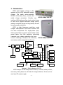
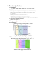
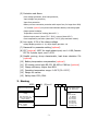
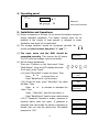
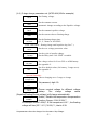
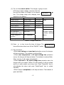
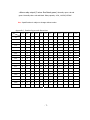
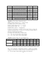
Version: 1.30.0004
KCG3 SMART BATTERY CHARGER
USER MANUAL
BEIYANG ELECTRIC APPARATUS FACTORY
TEL: 86-532-85775581
FAX: 86-532-85973847
ADDR: 66 JIANGXI ROAD, QINGDAO 266071, P. R. CHINA
WEB: www.byauto.com.cn
Email: [email protected]
1. Introduction
KCG3 smart battery charger is the
upgrade of our KCG2 automatic battery
charger. The inside micro-controller,
PIC18F of Microchip Corp., controls the
KCG3-120A/24V-3G
whole charge procedure. Friendly user
interface, LCD display and key input, makes it easy
to use. KCG3 supports different charge curves,
makes a complete charge and long battery life and
has all-around protections.
KCG3 is high frequency switching mode
charger. IGBT/MOSFET and PWM controller are
the main components. For single-phase input,
Active power factor correction circuit makes a high
power factor. And Soft switching technology
(resonant zero voltage switching and zero
current switching) increases the efficiency KCG3-200A/E80V-3G
and reduces electromagnetic interference.
Isolated Inverter
INPUT
EMI
filter
Rectifier
Rectifier &
filter
PFC
Battery
Snubber
Isolation & driver
Soft
start
Key input
Constant
Current
Temperature
sensor
PWM IC Control
Constant
Voltage
Power for
Control
Temperature
Switch
CPU
Fan cooling
Indicator
light
A、V、Status
LCD display
Reset
Relay/Beeper
ON/OFF
Diagram 1. Block diagram of KCG3
KCG3 charger can be widely used in Marine, e-forklift, railway vehicle,
and many other places for all kinds of storage batteries. It also can be
used as a DC power supply.
.1.
2. Technique Specifications
(1) Power supply:
1 or 3 phase, 220VAC, 380VAC, 440VAC, etc. –10%~+10%, 50/60Hz
(2) Outputs:
Rated output power = Equalize constant voltage (E. CV) * constant current (CC);
Different battery requires different E. CV, Floating CV (F. CV) and CC values;
e.g. 24V battery:
LA battery, we set 28.2V as E. CV and 26.7V as F. CV;
Alkaline battery, we set 31-36V as E. CV and 27.2V as F. CV;
Maximum output power: 20KW. See Appendix 1, 2. Support LA, GEL. See Appendix 3.
(3) Set charging parameter precision:
voltage: 0.1V; current: 1A
(4) Charge curve (programmable for any charge curve.):
(4-1) 3-stage charge
A: limited current / Boost, B: Constant Voltage, C: floating
Diagram 2. 3-stage recharge voltage/current curve.
(4-2) Other curves as customer’s requirement. E.g., 4-stage charge
A: Constant current 1, B: Constant Voltage 1, C: C.C. 2, D: C. V. 2
Diagram 3. 4-stage recharge voltage/current curve.
.2.
(5) Protection and Alarm:
Over voltage protection, Over load protection,
Input voltage low protection,
Input fuse protection.
Battery reverse connection protection with output fuse; for larger than 3KW,
DC contact (optional) can protect and eliminate battery connecting spark.
Output power limitation,
Temperature control fan cooling (about 45℃)
Reduce output power (about 75°C -78°C), resume (about 65°C)
Over temperature protection (about 80°C -85°C) (stop and auto restart).
(6) Low ripple, 0.3% of the charge voltage
voltage display precision: 0.1V; amps display precision: 1A
(7) Password for parameter setting (optional).
(8) PFC (optional). APFC for single phase input, cosΦ=0.99; Passive
PFC for 3-phase input, cosΦ>0.93.
(9) Parallel running, droop characteristic, load share deviation 5%
(optional)
(10) Battery temperature compensation (optional)
(11) PC remote control with RS-232, RS-485 or CAN bus (optional)
(12) Charge efficiency: Higher than 85%
(13) Operating temperature range: 0~50°C (32~122°F)
(14) Design for marine.
(15) Safety class: IP20, IP44.
3. Naming
KCG3-
A/ (E)xxx V-
Maximun output-current
Blank: Bench mount
W: Wall mount
xxxV: Nominal battery
voltage
INPUT
Blank: 220VAC
G: 380VAC
G1: 440VAC
G2: 110VAC
G3: 480VAC
G4: 600VAC
P1:110V, PFC
P2:220V, PFC
Start with letter "E",
xxxV is the maximum
output voltage
INPUT
Blank: 1 phase
3: 3 phase
.3.
4. Operating panel
KCG3
Battery Charger
Indicator
Light
Diagram 4.
Menu/
set
▲
▲
o-
ON
Back/
Cancel
Reset
User control interface.
OFF
5. Installation and Operations:
(1) Ensure a clearance of at least 10 cm around the battery charger to
ensure adequate ventilation. The battery charger must not be
installed in the vicinity of heat sources or exposed to water.
Ventilation slots must not be obstructed.
(2) The storage batteries should be connected correctly. Be OUTPUT
careful and don’t reverse the poles “+” and “-”.
+
-
▲
▲
accepted, user can modify the values; if password is
denied, user can view the values only. The default
password is “000”
.4.
024.0V 000A
Stop Charge
▲
▲
(3) The input wires and the GND should be
connected correctly. Then connect the AC power.
The LCD will show voltage, current and status.
(4) Set the charge parameters.
There are 5 buttons on the front panel. Press
“Back/Cancel”, when the LCD display abnormal. Menu/
set
If not work, press “Reset”.
(4.1) Press “Menu/Set” to enter the menu. Then
Press ▲
to choose item; or
Press “Back/Cancel”, quit the menu.
(4.2) Choose an item, press “Menu/Set”, the value
will flash. Then
Press ▲
to increase or decrease the
value. Then
Press “Menu/Set”, save the new value; or
Press “Back/Cancel” back to menu without save.
(4.3) If “Password” function is enable, password is
required before enter the menu. If password is
Back/
Cancel
Reset
1. Floating Volt
26.7V
2. Constant Curr
040A
024.0V 000A
Stop Charge
Enter Password
***
Password OK.
Password invalid
(4.4) 3-stage charge parameter set. (KCG3-40A/24V for example)
1. Floating Volt
Set floating voltage.
26.7V
2. Constant Curr
040A
Set the constant current.
Automatic change according to the Equalize voltage.
3. Equalize Volt
28.2V
Set the constant/equalize voltage.
4. Curr to Float
008A
Set the current value to floating charge.
5. Delay time
01 Hours
Set the floating charge time.
0,1, 2, 3 hours or NO STOP.
If set “NO STOP”, floating charge until equalize day (See 7.).
6. Over Volt.
Set the over voltage protection value
31.2V
7. Equalize day
20 Days
Set the cycle of equalize charge.
8. Set Battery
LA / GEL
Set voltage values for LA or GEL or AGM battery.
See appendix 2.
Set all to default values (LA battery, 3-stage curve).
See appendix 2.
9. Set default
YES
Set the Delay time “NO STOP” to enable.
Optional functions:
Choose charging curve 3-stage or 4-stage
10. Charge Curve
3-stage curve
11. Set Password
***
Set password, digit 0-9.
Choose nominal voltage for different voltage
battery.
The
charge
voltage
values
(Equalize/Floating/Protect voltage) will change automatically.
13. T. Compenst.
Enable / Disable the temperature compensation
DISABLE
function. Range: 0.01V-0.20V/℃
For example: set at 0.02V/C. If the temperture is 10℃, the floating
voltage will rise (25℃-10℃)*0.02V/℃, that is 0.3V.
12. Nominal Volt
24.0V
Set parameters when the charger is in the status: Stop Charge.
.5.
(5) Turn on the control switch. The charger is going to work.
LCD shows output voltage, current in the first
024.0V 000A
line and the status of charger in the second
Stop Charge
line. The charge stage and charging time
depend on the battery.
Status
Display
Indicator
Constant current
Equalize charge
Yellow flash
Constant voltage
Constant voltage
Yellow light
Floating charge
Floating charge
Green flash
Charge complete.
COMPLETED
Green flash
Over volt protection
OVER VOLTAGE
Red flash
Over Load protection
OVER HEAT
Auto restart
Over temperature
OVER LOAD
(If restart 3 times in
protection (80°C -85°C)
AC input voltage low
3-stage
Manually restart
1 minute, manually
restart.)
INPUT ABNORMAL
protection
Stop charge
STOP CHARGE
Green light
Table 1. Charger status list
(6) Press ▲
key to see the time of charge. The
time will be clean when turn off the “ON/OFF” switch.
026.7V 008A
00D 06H 15M
▲
(7) Stop and alarm
• When over voltage and over load protection occurs, the charger
will stop and alarm. The indicator is red and flash.
• When over temperature or AC input voltage low protection
occurs, the charger will stop and alarm. The indicator is red and flash.
When resume, it will restart automatically.
• When over load or AC input voltage low protection acts, the
charger will try to restart 3 times. If it still protects, it will not restart
and try to auto restart once every hour. Press “Menu/Set” key to
acknowledge the alarm and press “Back/Cancel” key to restart
manually.
• When charge is completed, it will stop and alarm. The indicator is
green and flash.
.6.
• Alarm relay output (3 wires. Red black green). Normally open: red and
green. Normally close: red and black. Relay capacity: 0.3A, 110VDC/125VAC.
Note: Specifications is subject to change without notice.
Appendix 1. Standard types and dimensions.
V.
C.
12V
24V
36V
48V
60V
72V
80V
96V
108V
192V
216V
324V
B
B
3A
5A
10A
A
15A
A
A
20A
A
25A
A
A
A
B
B
A
30A
A
B
C
C
A
B
B
C
C
B
B
C
C
D
C
C
D
D
D
C
C
D
D
E
B
C
C
C
C
D
E
E
E
40A
A
A
B
C
C
C
D
D
D
E
E
F
50A
A
B
C
C
C
D
D
D
E
F
F
G
60A
A
B
C
C
D
D
D
E
E
F
F
G
70A
B
C
C
D
D
D
D
E
E
F
G
80A
B
C
C
D
D
D
E
E
F
G
G
90A
B
C
D
D
D
E
E
F
G
100A
B
C
D
D
E
E
E
F
F
120A
C
C
D
D
E
E
F
F
F
130A
C
D
D
E
F
F
F
F
G
150A
C
D
D
E
F
F
G
G
G
180A
C
E
E
F
F
G
G
G
200A
C
E
E
F
G
G
G
.7.
Dimensions (mm)
Weight (KG)
POWER(KW)
Bench mounted, 350×243×113 mm
6-7
≤1.2
Wall mounted, 350×140×500 mm
10
Bench mounted, 370×310×113 mm
8-9
Wall mounted, 350×140×500 mm
12
C
Bench mounted, 460×350×128 mm
12-14
≤3.6
D
Bench mounted, 520×380×150 mm
20-22
≤6.5
E
Bench mounted, 550×430×160 mm
25-28
≤10
F
Cabinet, 540×260×1000 mm
50-60
≤15
G
Cabinet, 600×320×1000 mm
65-75
≤20
A
B
≤1.8
Appendix 2. Choose charge voltage and current
Voltage: charging voltage per cell × number of cells;
For example, 9 pcs of 12V LA battery in series
Equalize constant voltage, 14.1V × 9 = 119.7V,
Floating constant voltage, 13.4V × 9 = 126.9V
Current: Battery capacity × charging factor.
If choose 0.1 as the factor, it will take no more than 16 hours to charge the
completed discharged battery. If choose 0.2, it will take less than 8 hours to
charge the completed discharged battery.
For example, 48V 630Ah battery, Constant current,
0.1 × 630 = 63A. So choose 60A or larger charger;
0.2 × 630 = 126A. Choose 120A or larger charger.
Appendix 3. Default voltage, for 3-stage charging curve.
Battery Nominal Voltage
12V
24V
48V
60V
72V
80V
216V
LA/VRLA/AGM
Floating
13.4V
26.7V
53.4V
66.5V
80.0V
89.3V
241V
Equalize
14.1V
28.2V
56.4V
70.5V
84.6V
94.0V
254V
Floating
13.5V
27.0V
54.0V
67.5V
81.0V
90.0V
243V
Equalize
14.3V
28.6V
57.2V
71.5V
85.8V
95.3V
257V
GEL
AGM: Absorbed Glass Matt
Note: If the temperature compensation function is enabled, the charging
voltages set in the menu are voltages when the environment temperature is at
25℃. The real output voltage changes according to the temperature.
.8.