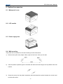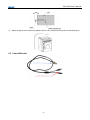
1
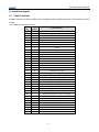
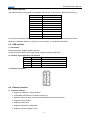
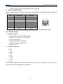
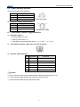
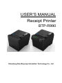
USER’S MANUAL Receipt Printer BTP-R990 Shandong New Beiyang Information Technology Co., Ltd BTP-R990 User’s Manual Declaration Information in this document is subject to change without notice. SHANDONG NEW BEIYANG INFORMATION TECHNOLOGY CO., LTD. (hereinafter referred to as “SNBC”) reserves the right to improve products as new technology, components, software, and firmware become available. If users need further data about this product or have any doubt about safety issues that might arise from using it, please feel free to contact your local dealer. No part of this document may be reproduced or transmitted in any form or by any means, electronic or mechanical, for any purpose without the express written permission of SNBC. Copyright Copyright © 2011 by SNBC Printed in China Version 1.0 Trademark SNBC registered trademark: Warning and Caution Warning: Items shall be strictly followed to avoid injury or damage to body and devices. Caution: Items with important information and prompts for operating the printer. Certification Quality control system of SNBC has been approved by the following certificates: ISO9001 quality control system certification ISO14001 environmental control system certification OHSAS18001 profession health safety control system certification IECQ QC080000 hazardous material process control system certification BTP-R990 has been approved of the following environmental protection certificates: -1- BTP-R990 User’s Manual General Safety Information Before installing and using the printer, please read the following items carefully. 1. Safety instructions Warning: Do not touch the cutter of the printer. Warning: The print head is a thermal element and it is at a high temperature during printing or just after operation, therefore do not touch it or its peripherals for reasons of safety. Warning: The print head is an ESD-sensitive device. To avoid damage, do not touch either its printing parts or connecting parts. 2. Caution 1) Install the printer on a flat and stable place. 2) Reserve adequate space around the printer so that convenient operation and maintenance can be performed. 3) Keep the printer away from water source. 4) Do not use or store the printer in a place exposed to heat of fire, moisture, serious pollution and direct sunlight. 5) Do not place the printer on a place exposed to vibration or impact. 6) No dew condensation is allowed to the printer. In case of such condensation, do not turn on the power until it has completely evaporated. 7) Connect the DC adapter to an appropriate grounding outlet. Avoid sharing a single electrical with large power motors and other devices that may cause the fluctuation in voltage. 8) Disconnect the DC adapter when the printer is not used for a long time. 9) Don’t spill water or other materials on the printer. If this happens, turn off the power immediately. 10) Do not allow the printer to start printing when there is no recording paper installed, otherwise the print head and platen roller will be damaged. 11) To ensure quality print and normal lifetime, use recommended or good quality paper. 12) Shut down the printer when connecting or disconnecting interfaces connectors to avoid damage to the control board. 13) Set the print darkness to a lower grade as long as the print quality is acceptable. This will help to keep the print head durable. 14) The printer should only be disassembled or repaired by a technician, who is certified by the manufacturer. 15) Keep this manual safe and at hand for ready reference. 16) The following content about cutter only applies to printers with cutter. -2- BTP-R990 User’s Manual Content 1 Introduction..........................................................................................................................................1 1.1 OUTLINE ........................................................................................................................................1 1.2 FEATURES .....................................................................................................................................1 2 Specifications ......................................................................................................................................2 2.1 MAIN SPECIFICATION.......................................................................................................................2 2.2 CUTTER SPECIFICATION ..................................................................................................................2 2.3 PAPER SPECIFICATION ....................................................................................................................3 2.3.1 2ST paper ..........................................................................................................................3 2.3.2 Marked paper.....................................................................................................................3 2.4 PRINT AND TEAR OFF POSITION........................................................................................................4 2.4.1 Print position ......................................................................................................................4 2.4.2 Tear off position .................................................................................................................4 3 Appearance and components..............................................................................................................5 3.1 APPEARANCE AND COMPONENTS.....................................................................................................5 3.2 LED AND BUZZERS .........................................................................................................................6 4 Installation ...........................................................................................................................................7 4.1 UNPACKING....................................................................................................................................7 4.2 PRINTER INSTALLATION ...................................................................................................................7 4.3 CONNECTING POWER ADAPTER .......................................................................................................7 4.4 CONNECTING COMMUNICATION CABLE .............................................................................................8 4.5 CONNECTING USB CABLE ...............................................................................................................8 4.6 CONNECTING THE CASH DRAWER CABLE .........................................................................................8 4.7 PAPER ROLL LOADING .....................................................................................................................8 4.7.1 Confirm the paper type ......................................................................................................8 4.7.2 Load/replace paper roll ......................................................................................................9 4.8 PAPER NEAR END ADJUSTMENT .....................................................................................................10 4.8.1 Paper near end position adjustment ................................................................................10 4.8.2 Remaining paper amount adjustment of paper near end sensor .....................................10 4.9 POWER ON PRINTER AND PRINT SELF-TEST PAGE ............................................................................11 -3- BTP-R990 User’s Manual 4.9.1 Power on printer ..............................................................................................................11 4.9.2 Print self-test page ...........................................................................................................11 4.10 GUIDE FOR HEXADECIMAL DUMPING MODE .....................................................................................11 4.10.1 Hexadecimal dumping function........................................................................................11 4.10.2 Running hexadecimal dumping........................................................................................11 5 Routine maintenance ........................................................................................................................13 5.1 PRINT HEAD AND ROLLER CLEANING ..............................................................................................13 5.2 MARK SENSOR CLEANING..............................................................................................................13 5.3 CLEAR PAPER JAM ........................................................................................................................13 6 Interface signal ..................................................................................................................................14 6.1 PARALLEL INTERFACE ...................................................................................................................14 6.2 SERIAL INTERFACE .......................................................................................................................15 6.3 USB INTERFACE ...........................................................................................................................15 6.4 ETHERNET INTERFACE ..................................................................................................................15 6.5 WLAN INTERFACE ........................................................................................................................16 6.6 POWER INTERFACE DEFINITION .....................................................................................................17 6.7 CASH DRAWER INTERFACE SIGNAL DEFINITION................................................................................17 7 Troubleshooting.................................................................................................................................18 7.1 PRINTER DOESN’T WORK...............................................................................................................18 7.2 ERROR LED AND BUZZER .............................................................................................................18 7.3 PROBLEMS DURING PRINTING ........................................................................................................18 8 Optional accessories .........................................................................................................................19 8.1 WATERPROOF COVER ...................................................................................................................19 8.2 LCD MODULE ...............................................................................................................................19 8.3 POWER SUPPLY BOX .....................................................................................................................19 8.4 WALL MOUNTING ..........................................................................................................................19 8.5 POWERUSB CABLE ......................................................................................................................20 9 Power Management ..........................................................................................................................21 Appendix: Button configuration menu.....................................................................................................22 -4- BTP-R990 User’s Manual 1 Introduction 1.1 Outline BTP-R990 is a 2-side thermal receipt printer developed for high-end thermal receipt printing market. It can be widely applied in many real-time printing fields, such as retail, restaurant, finance, telecommunications, logistics, transportation, lottery, entertainment and parking, etc. BTP-R990 can be connected with other devices via parallel, serial, USB, Ethernet, WLAN, or Bluetooth interface, and can provide drivers for operating systems such as WINDOWS 2000 / XP / Server2003 / VISTA / Server2008 / WIN7, Linux, MAC and UPOS middleware. 1.2 Features ¾ 2-side thermal (2ST) printing ¾ Low noise, high printing speed ¾ Easy paper loading ¾ Support voice prompt(optional) ¾ Support LCD prompt(optional) ¾ Support continuous paper and marked paper(optional) ¾ Compatible with various paper width between 54.5~82.5mm ¾ Cutting paper automatically ¾ Cash drawer control connector ¾ Communication connector optional ¾ Compatible with ESC/POS commands ¾ Volume of buzzer on-board can be adjusted ¾ Support save paper function ¾ Support Gray scale printing and Bi-colour printing ¾ Low power consumption design (Min. power consumption is about 1W): the default waiting time of entering sleep mode is 5 minutes. -1- BTP-R990 User’s Manual 2 Specifications 2.1 Main specification Item Specification Print Method Direct thermal line printing Print resolution 203×203dpi Max. 1ST print speed: >310mm/s; Max. 2ST print speed: >175mm/s Max.80mm Print speed Print width Paper type 2ST paper One-dimensional barcode: CODE128,ITF, UPC-A, UPC-E, EAN13, EAN8, CODE39, CODE93, CODABAR Two-dimensional barcode:PDF417,QR,MaxiCode GS1 barcode Font A:12×24; Font B:9×17; Kanji Font A: 24×24; Optional: Simplified Chinese, Traditional Chinese, Korean, Japanese, English etc. Code page: 57kinds of code page; International character sets: 14kinds of character sets; All characters can be enlarged 1~6 times horizontally and vertically respectively. Rotation print in four directions (0°, 90°, 180°, 270°) Barcode Characters Character enlargement Character rotation Paper detection Photoelectric sensor (out of paper) Top cover position detection Micro switch Print head temperature detection Thermal resistor Print head lifetime Bitmap download Direct bitmap print Download buffer size: Support bitmap mode, fast graphic RAM:128KB print. FLASH:Max.2MB USB interface (Fixed on board) Standard parallel interface or RS232 serial interface, RS485 interface,Ethernet interface, WLAN interface,Bluetooth interface (optional) 2 drives RAM:4MB FLASH:4 MB/8MB DC 24V±5%, average current 2.0A Max. 11A ≥150Km(standard test sample of 12.5% duty ratio) Operation temperature and humidity 5~45℃, 10%~93% (40°C) Storage temperature and humidity -40~60℃, 20%~93% (40℃) Overall dimension 207mm×147mm×156mm(L×W×H) Graphic process Communication interface Cash drawer interface Memory Power supply 2.2 Cutter Specification Item Parameter Remarks Cutter type Slide cutter Cutting time 500ms The time that one cut takes Cutting interval 3s Paper type 0.06~0.15mm 20 cuts/min. (Max.) Thermal paper or normal paper with the same thickness Operation voltage 24V DC Max. operation current 1.2A 2000,000 cuts (paper thickness is 0.065mm) Cutter lifetime -2- 24V DC BTP-R990 User’s Manual 2.3 Paper Specification 2.3.1 2ST paper ¾ Paper type: 2 ST paper ¾ Paper supply method: Paper roll ¾ Paper width: 54.5-82.5mm adjustable ¾ Paper thickness:0.06mm-0.15mm ¾ Thermal sensitive layer: 2-side thermal layer ¾ Paper roll specifications: OD(Max):ф83 mm Caution: Please use the recommended reference paper type or its equivalents. Using the lower quality paper types might affect the print quality and shorten print-head life. If the paper is contaminated by chemical or oil, it may discolor or lose heat sensitivity at the polluted spot. Do not rub the paper surface strongly against hard objects, otherwise it may discolor. When the temperature exceeds 70°C, the thermal layer will fade. Thus, do not use or store the paper in a place exposed to high temperature, high humidity, strong light, etc. 2.3.2 Marked paper BTP-R990 can support marked paper printing and set the cutting and initial printing position accurately. Marked paper not only should meet the parameters of thermal paper roll, but also should meet the following requirements: ¾ L1 mark height:3mm≤ L1≤13mm ¾ L2 mark length: 2mm≤L2 ¾ L3 distance between two marks:20mm≤L3≤500mm ¾ Mark position: any position, default is at the left side ¾ Reflectivity: The reflectivity of the black mark must be less than 15% while the reflectivity of the paper itself exceeds 85%. ¾ The mark specification of 2-side marked paper is the same as that of 1-side marked paper. -3- BTP-R990 User’s Manual 2.4 Print and tear off position 2.4.1 Print position L1: Paper holder width: 83.5+0/-0.5mm L2:Max Print width: 80mm L3: Distance between left end of print-head and left side of paper house (Fixed) 1.75±1mm L4:Distance between right end of print-head and right side of paper house(Fixed) 1.75±1mm L5: Left margin (default:8mm) L6: Print area width. Can set by command (See Programming Manual),default is 64mm L7: Right margin (default: 8mm) 2.4.2 Tear off position L1:31.3mm L2:13mm L3:21.7mm; L4:16.2mm Notes: After retracting paper for compensation, the minimum distance of blank page header can up to 2mm; -4- BTP-R990 User’s Manual 3 Appearance and components 3.1 Appearance and components 1—tear off bar 2—top cover 3—cover open lever 4—feed button 5—error LED 6—power LED 7—power switch 8—bottom cover 9—middle cover 10—power interface 11—cash drawer interface 12—USB interface 13—interface board 14—roller on top cover 15—thermal print head 17—paper guide 18—paper near end lever 20—cutter sliding blade 21—paper cabinet 16—2ST paper sensor 19—paper near end sensor 22—black mark sensor 23—cutter fixed blade 24—thermal print head 25—roller on the base 26—paper end sensor 27—thumb wheel for adjusting paper guide 28—last ticket sensor Component function: a. Power LED Indicate printer power status (ON/OFF). b. Error LED Indicate printer status. Under normal conditions, ERROR LED is always off. Under error conditions (e.g. print head lift up, voltage abnormal, print head overheating, cutter error, can not find mark, etc.), ERROR LED will flash. c. Feed button Feed paper: Printer will feed paper when the FEED BUTTON is pressed down under normal condition. Printer will feed long length paper if keeps pressing down the button. Print self-test page: -5- BTP-R990 User’s Manual Press down FEED button while turn on the power, the printer will print out the self-test page, including print width, print speed and so on. Enter button configuration mode: Pressing down FEED button while turning on the printer, the printer will print out configuration sample, then cut paper and enter waiting status (ERROR LED flashes). The printer will enter button configuration mode (Parameter setting (configuring) by Feedbutton) if pressing down the FEED button for a long time at this time. Refer to Appendix Button Configuration Menu for detailed function and operation methods of button configuration mode. d. Power switch Press down “O” to turn off power, and press down “—”to turn on power. e. Top cover uplifting alarm sensor f. Monitor top cover status(open/close). Paper end sensor To detect if paper is existing or not. g. Paper guide Rotate the thumb wheel for adjusting the paper guide in paper cabinet, in order to meet paper for different print width 54.5±0.5 mm~82.5±0.5 mm. h. Paper near end sensor To detect the paper roll status. Flashing of error LED indicates that the paper will be used out soon and user should replace the paper roll in time.Printer will work normally until paper ends. 3.2 LED and Buzzers 1) 2) Functions of LED & Buzzer LED name Status POWER LED (green) Always on Printer power is on. Off Printer power is off. Off Printer is in normal status Printer is in error status, or paper is near end. Printer is in error status. ERROR LED (red) Flash Buzzer Beep Description Error type indicated by LED & buzzer Error Type ERROR LED Buzzer Print head is overheating Cycle flash 6 times Cycle beep 6 times Input voltage is abnormal Cycle flash 5 times Cycle beep 5 times Cutter error Cycle flash 4 times Cycle beep 4 times Print head lifts up Cycle flash 3 times Cycle beep 3 times Paper end Cycle flash 2 times Cycle beep 2 times Paper near end Mark can not be found or verify failed Flash slowly Not beep Flash slowly Not beep Caution: The temperature of the print head is detected by a thermal resistor. If the print head is overheating, the protective circuit will shut off the power and force the printer to stop printing; the temperature of print head when printing is stopped is 65℃. -6- BTP-R990 User’s Manual 4 Installation 4.1 Unpacking Check whether all items, which are listed on the packing list, are present and in a good condition. If any item is damaged or missing, please contact your dealer 4.2 Printer installation 1) BTP-R990 can be installed in two methods: horizontally on table, and vertically on wall. a) Horizontally on table: incline installation angle should not exceed ±15°; b) Vertically on wall: please refer to Chapter 8.4. a. Install horizontally on table b. Install vertically on wall 2) Keep the printer far away from water source; 3) Do not place the printer in the place exposed to vibration and impact; 4) Must guarantee the printer safety ground; 5) Recommend to keep proper space, in order to guarantee the reliability and operational convenience of the printer. 4.3 Connecting power adapter 1) Ensure the power switch is turned off; 2) Insert the power cord into the power socket on the back of the printer. -7- BTP-R990 User’s Manual Caution: When the printer is not in use for a long period of time, disconnect the power cord from the printer. 4.4 Connecting communication cable 1) Ensure the power switch is turned off; 2) Insert the interface cable into suitable interface, and fix the cable connector with screw and chip spring. 3) Connect the other end of the interface cable to the host. 4.5 Connecting USB cable 1) Confirm the power switch is turned off. 2) As shown in the figure, insert the USB cable into the USB interface, ensure they are matched and lead the cable through the cable hook to avoid dropping off of USB cable. The other end of USB interface cable should be connected to the host. 4.6 Connecting the Cash Drawer cable 1) Confirm the printer power is turned off. 2) Insert the cash drawer cable into the cash drawer connector on the back of the printer. Caution: Cash drawer interface can be connected only with a cash drawer device (Do not connect a telephone line and so on). 4.7 Paper roll loading 4.7.1 Confirm the paper type After connecting the power cable and interface cables, paper can be loaded for printing. Confirm the paper type is correct before printing. -8- BTP-R990 User’s Manual 4.7.2 Load/replace paper roll 1) Turn off the printer; 2) Open the printer top cover;. 3) Place a paper roll in the paper cabinet; 4) Pull out the paper end of paper roll, close top cover, and tear off the surplus portion of the paper. Caution: Adjust the paper guide according to paper specification: adjust the paper guide to Max. width and place paper roll in the paper cabinet; rotate the thumb wheel to adjust the paper guide to suitable place(1mm gap between paper roll and paper guide should be reserved, to avoid paper roll being snapped ); the paper roll rotation direction should meet printer requirements. Confirm that the paper is rolled tightly on the paper roll, otherwise, paper jam or other fault may occur; Paper roll should be placed stably in the paper cabinet without incline, or the printing will be affected. -9- BTP-R990 User’s Manual 4.8 Paper near end adjustment 4.8.1 Paper near end position adjustment BTP-R990 supports printing in horizontal and vertical positions. Users can realize the detection of remaining paper in horizontal and vertical by adjusting the position of paper near end sensor. The default printer setting is horizontal printing and the paper near end sensor is at the bottom of the paper cabinet. To change the paper near end sensor position: First, press the plastic slip in position 1 along the direction of the arrow. Then rotate thumb wheel in the direction shown in the figure. The paper near end sensor will start to rotate. When the plastic slip reaches at position 2, the change of paper near end sensor position from horizontal to vertical is complete. Reverse operation will change the paper near end sensor position from vertical to horizontal. 4.8.2 Remaining paper amount adjustment of paper near end sensor Remaining paper amount can be adjusted by adjusting the position of paper near end sensor. Paper near end sensor has six levels, the dark part (real object on printer is raised) shows the current level, and the red mark can be adjusted to a different position by moving the thumb wheel, through which the remaining paper amount is changed. - 10 - BTP-R990 User’s Manual 4.9 Power on printer and print self-test page 4.9.1 Power on printer 1) Confirm that the printer is connected to power; 2) Turn on the power switch to power on the printer. 4.9.2 Print self-test page 1) Confirm that the printer is connected to power, and load paper roll; 2) Confirm that the printer is switched off; 3) Press down the FEED button while turning on the printer power, the printer will print out configuration information and prompt characters “Press feed key to continue”. Then printer enters pause and waiting status, and the ERROR LED is flashing; 4) Press down the FEED button momentarily, the printer will print a character test page, and the printing of self-test page is complete. 5) Following step 3), the printer will enter button configuration mode (Parameter setting (configuring) by Feedbutton) if pressing down the FEED button for a long time at this time. Refer to Appendix Button Configuration Menu for detailed function and operation methods of button configuration mode. 4.10 Guide for hexadecimal dumping mode 4.10.1 Hexadecimal dumping function This function prints the data transmitted from the host computer in hexadecimal numbers and in their corresponding characters. Print sample in Hexadecimal Dump mode: 4.10.2 Running hexadecimal dumping 1) Start hexadecimal dumping by executing either of the following: a. Open the top cover, turn the power on while pressing the Feed button until the printer alarms (LED flashes, buzzer beeps), and then close the top cover, then the printer will enter hexadecimal dump mode. Please wait for the printer alarm after turning on the power, otherwise the printer will not enter hexadecimal dump mode. b. Execute the GS ( A command. 2) The printer first prints "Hexadecimal Dump To terminate …..", and then prints the received print data in hexadecimal numbers and in their corresponding characters. 3) After printing has been finished, Hexadecimal dumping ends by executing any of the following: a. Turn the power off. - 11 - BTP-R990 User’s Manual b. Press the Feed button three times. Caution: If no characters correspond to the data received, the printer prints "." During hexadecimal dumping, any commands other than DLE EOT, DLE ENQ, or DLE DC4 do not function. Insufficient print data to fill the last line can be printed by pressing down the Feed button. - 12 - BTP-R990 User’s Manual 5 Routine maintenance Caution: Before starting routine maintenance, confirm that the printer power is turned off. Do not use solvents like gasoline or acetone. When cleaning sensors, the printer should not be switched on until the pure alcohol has totally evaporated. It is recommended that the maintenance cycle should not be longer than one month. 5.1 Print head and roller cleaning Steps for TPH and roller cleaning are as follows: 1) Turn off the printer and open the top cover; 2) If printing is just finished, please wait for the print head to cool down completely; 3) Wipe off dust and stains on the surface of the print head and roller with soft cotton cloth dipped with pure alcohol (it should be wrung out); 4) Wait until the alcohol is completely evaporated, then close the top cover. 5.2 Mark sensor cleaning If the printer does not identify the mark effectively, you should clean the mark sensor. Steps for mark sensor cleaning are as follows: 1) Turn off the printer; 2) Pull the latch to open the back cover of the printer; 3) Wipe off dust and stains on the surface of the sensor with soft cotton cloth dipped with pure alcohol (it should be wrung out); 4) Wait until the alcohol is completely evaporated, then close the back cover and finish sensor cleaning. 5.3 Clear paper jam 1) Turn off the printer power, rotate the cover open lever, and the cutter sliding blade will release the cutter cover during the top cover open(top cover and cutter cover are released at the same time); 2) Clear paper jam, close the top cover and cutter cover; 3) Turn on the printer power. Caution: Slowing open the top cover and cutter cover, and carefully check during the opening. Do not force suddenly so as to avoid damaging the cutter sliding blade. - 13 - BTP-R990 User’s Manual 6 Interface signal 6.1 Parallel interface Parallel interface can work in IEEE 1284 compatible mode or nibble byte mode. The interface is 36PIN socket. The Interface is defined as below: PIN No. Signal source Signal definition 1 H nStrobe 2 H Data 0 (Least Significant Bit) 3 H Data 1 4 H Data 2 5 H Data 3 6 H Data 4 7 H Data 5 8 H Data 6 9 H Data 7 (Most Significant Bit) 10 P nAck 11 P Busy 12 P Perror 13 P Select 14 H nAutoFd 15 Not defined 16 Logic Gnd 17 Chassis Gnd 18 P Peripheral Logic High 19 Signal Ground (nStrobe) 20 Signal Ground (Data 1) 21 Signal Ground (Data 2) 22 Signal Ground (Data 3) 23 Signal Ground (Data 4) 24 Signal Ground (Data 5) 25 Signal Ground (Data 6) 26 Signal Ground (Data 7) 27 Signal Ground (Data 8) 28 Signal Ground (PError, Select, and nAck) 29 Signal Ground 30 (Busy and nFault) Signal Ground (nAutoFd, nSelctIn, and nInit) 31 H nInit 32 P nFault 33 Not defined 34 Not defined 35 Not defined 36 H nSelectIn - 14 - BTP-R990 User’s Manual 6.2 Serial interface The serial interface of the printer is compatible with RS-232, its connector is 25PIN female D type. PIN No. Signal definition PIN1 Frame Ground PIN2 TXD PIN 3 RXD PIN 4 RTS PIN 5 Not connected PIN6 DSR PIN 7 Signal Ground PIN 8~19 Not connected PIN 20 DTR PIN 21~25 Not connected User can query interface settings status via printing self-test page. The default setting is as follows: Baud rate: 19200bps; Data bit: 8; Parity bit: none; Stop bit: 1; Handshake: DTR/DSR 6.3 USB interface 1) Parameters Data transmission: Support USB2.0 protocol Connector (Printer side): USB A type socket. Support and pass USB HUB 2) Interface signal definition and function PIN Signal Name Description 1 VBUS +5V 2 DATA- Printer data transmit line (minus) 3 DATA+ Printer data transmit line (plus) 4 GND Ground 3) Interface connector 6.4 Ethernet interface 1) Interface features ¾ Support of 10BASE-T communication ¾ Compatible with Ethernet II standard frame type ¾ Indicator shows network connecting status and data transmission status ¾ Supports 9100 port print ¾ Supports status back ¾ Supports parameter configuration ¾ Supports firmware update on-line - 15 - BTP-R990 User’s Manual ¾ Supports printer status query and interface module maintenance based on HTTP(only JK-E02 interface supports, while JK-E04 interface does not support) 2) Interface signal definition Interface adopts 10BASE-T standard in accordance with IEEE802.3. The interface signal is defined as below: PIN Signal Name Instruction 1 TX+ 2 TX- Data transmission + Data transmission - 3 RX+ Data receiving + 4 NC Reserve 5 NC Reserve 6 RX- Data receiving - 7 NC Reserve 8 NC Reserve Pin list of interface module Socket of Interface module 6.5 WLAN interface 1) Interface features ¾ Supports 802.11b, 802.11g communication ¾ Supports 9100 port printing, LRP printing ¾ Supports status back ¾ Supports parameter configuration ¾ Supports Firmware update on-line ¾ Supports HTTP 2) Protocols supported ¾ IP ¾ ARP ¾ ICMP ¾ TCP ¾ UDP ¾ DHCP ¾ TFTP ¾ HTTP Some wireless interfaces use wireless USB network card, the main specification of which should be requested from the local distributor or manufacture. - 16 - BTP-R990 User’s Manual 6.6 Power interface definition AC power interface signal definition: PIN Signal Name 1 2 E L 3 N AC Power socket DC 24V power interface signal definition PIN Signal Name 1 +24V 2 GND NC 3 DC 24V Power socket 6.7 Cash drawer interface signal definition 1) Electrical features ¾ Driving voltage: DC 24 V ¾ Driving current: Max. 1 A ¾ Cash drawer status inspection signal: “L” = 0~0.5 V “H” = 3.3 V 2) Cash drawer interface outlet uses RJ-11 6P connector: 3) Interface signal definition PIN Signal Name 1 FG 2 DRAWER 1 3 DRSW 4 VDR 5 DRAWER 2 6 GND Functions Frame Ground Cash drawer 1 driving signal Cash drawer status test signal Cash drawer driving power Cash drawer 2 driving signal Circuit share ground Caution: Do not connect or disconnect communication cable when printer power is on; Communication cable should be far away from strong current; Communication cable should adopt shield cable. - 17 - BTP-R990 User’s Manual 7 Troubleshooting In case of printer fault, consult this section for solutions and advice. If you do not find a solution in this section, please contact your local dealer for assistance. 7.1 Printer doesn’t work Problems Possible causes LED is off and the printer doesn’t work Solution Printer has no power supply Connect the printer power. Printer power is off Turn on the printer power. Circuit is damaged Contact your local dealer or manufacturer. 7.2 Error LED and Buzzer Problems Error LED flashes or buzzer beeps Possible causes Solution Paper end Replace roll paper. Cutter error Refer to 7.4 Cutter error troubleshooting. Top cover lifts up Close top cover. Print head is overheating Turn off printer power and wait until the print head turn to normal temperature. 7.3 Problems during printing Problems Possible causes Paper cannot be fed normally Paper jam Printer starts printing but stops suddenly during printing Paper jam Open top cover to check paper path and cutter and remove paper jam. Open top cover to check the cutter and remove paper jam. Printer status is abnormal Paper is not cut Paper jam Paper roll is not installed correctly Paper is out of specification Printout is not clear or dirty Dirty print head or platen roller Print darkness is too low Vertical column of print is missing Solution Dirty print head or platen roller Print head error - 18 - Solve as per Chapter 7.2. Open top cover to check the cutter and remove paper jam. Make sure that the paper roll has been installed correctly. Use recommended thermal paper. Clean the print head or the platen roller. Increase the print darkness as needed. Clean the print head or the platen roller. Contact your local dealer. BTP-R990 User’s Manual 8 Optional accessories 8.1 Waterproof cover 8.2 LCD module 8.3 Power supply box 8.4 Wall mounting The printer can be mounted on the wall according to below instructions: 1) Drill two holes (OD: 6mm; depth: 50mm, space of two hole: 75mm) on the wall: 2) Insert the plastic expansion pipe in the holes and make sure that the pipe end is parallel to the wall surface: 3) Screw the screws into the plastic expansion pipe and keep10mm space between the screw head and the wall surface: - 19 - BTP-R990 User’s Manual 4) Adjust the paper near end sensor (please refer to 4.8.1) and mount the printer as following figure: 8.5 PowerUSB cable - 20 - BTP-R990 User’s Manual 9 Power Management The power management of BTP-R990 has four operation modes: Ready, Active, Sleep, Off. 1) Printer will enter into Ready mode after powering on printer or completing printing job. 2) Printer will enter into Sleep mode if there is not any printing job for 5 minutes in Ready mode. 3) Printer will awake automatically and enter into Active mode when printing job comes, and will enter into Ready mode again after completing printing job. Relating Parameters of power management are as below: Maximum Default Delay Times < 5minutes; Because the Maximum Default Delay Times is less than 5 minutes, BTP-R990 does not open this port for user to change the time. - 21 - BTP-R990 User’s Manual Appendix: Button configuration menu Refer to BTP-R990 Printer's Parameter Setting Menu by Feed Button. - 22 -