1
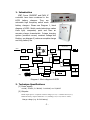
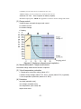
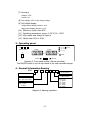
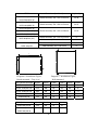
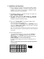
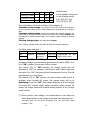
Ver 1.50.0003
KCG-2 SWITCH MODE BATTERY CHARGER
USER MANUAL
BEIYANG ELECTRIC APPARATUS FACTORY
TEL: 86-532-85849015
FAX: 86-532-85814619
ADDR: 66 JIANGXI ROAD, QINGDAO 266071, P. R. CHINA
WEB: www.byauto.com.cn
Email: [email protected]
1. Introduction
IGBT, Power CMOSFET and PWM IC
controller have been contained in the
KCG2 battery chargers. They are
automatic high frequency switch mode
battery chargers. Please see Diagram 1, block
diagram of KCG2. Switch mode technology makes
them light, compacted, quiet and have an
accurate charge characteristic. 3-stage charging
system (constant current, constant voltage and
floating, see diagram 2) makes a complete charge
and long battery life.
Isolated Inverter
INPUT
EMI
filter
Amp Volt LED
Rectifier &
filter
Rectifier
Battery
Temperature
control fan
Limited
Current
Isolation & driver
Floating
Constant
Voltage
PWM IC Control
Equalizing
Soft start
Charge mode
control
Over Load
Lamp
Protection
Over Voltage
Over Heating
Relay
Temperature Switch
Charge
parameters
Reset
Diagram 1. Block diagram of KCG2
2. Technique Specifications
(1) Power supply:
110VAC, 220VAC, 3φ380VAC, 3φ440VAC, etc. 50/60HZ
(2) Outputs:
Rated output power = Equalize constant voltage (E. CV) * constant current (CC);
Different battery requires different E. CV, Floating CV (F. CV) and CC values;
Charge voltage (e.g. for 24V battery)
.1.
LA battery, we set 28.2V as E. CV and 26.7V as F. CV;
Alkaline battery, we set 31-36V as E. CV and 27.2V as F. CV;
Maximum CC: 20A -- 200A. Depends on battery capacity.
Maximum output power: 10KW. See Appendix 1 on how to choose voltage and current.
(3) Charge control:
3-stage charge; automatic charge mode control.
A: Constant current
B: Constant Voltage
C: floating
Diagram 2. Recharge voltage/current regulation.
(4) Manual/Automatic* Charge mode control.
*Automatic charge mode control function is optional.
(5) 3-level temperature protection
1. Temperature control fan cooling (about 45℃)
2. Reduce charge voltage (about 75°C -78°C), resume (about 65°C) *(optional)
3. Over temperature protection (about 80°C -85°C)
(6) Protection:
over load (manually reset),
over voltage (manually reset),
over temperature (auto reset) and
output short circuit.
.2.
(7) Accuracy:
voltage: 0.5%
current: 1%
(8) Low ripple, 0.5% of the charge voltage
(9) LED digital display:
voltage meter display precision: 0.1V
amps meter display precision: 0.1A
(10)
(11)
(12)
(13)
Efficiency: higher than 80%
Operating temperature range: 0~50°C (32~122°F)
High quality and design for marine.
Safety class: IP20 or IP44.
3. Operating panel
KCG2
-
A/
V-
Over volt
Battery Charger
Voltage
Voltage
Over temp.
Current
Over load
V
A
o-
ON
Floating
OFF
- -
Reset
Equalizer
Diagram 3. Front panel outline. (Bench-mounted.)
The ON/OFF switch is on the right hand in the wall-mounted charger.
4. General Information Naming
KCG2-
A/
V-
Maximun output-current
Blank: Bench mounted
W: Wall mounted
Blank: Lead acid Battery
A: Alkaline Battery
xx : Nominal battery voltage
Exx : Max output voltage
INPUT
Blank: 220VAC
G: 380VAC
G1: 440VAC
G2: 110VAC
G3: 480VAC
G4: 600VAC
INPUT
Blank: 1 phase
3: 3 phase
Diagram 4. Naming regulation.
.3.
Dimensions (L x W x H)
Weight(Kg)
Bench-mounted, 550 x 430 x 160 mm
25-28
Bench-mounted, 520 x 380 x 150 mm
20-22
Bench-mounted, 460 x 350 x 128 mm
11-14
Bench-mounted, 370 x 310 x 113 mm
8
Wall-mounted, 350 x 140 x 500 mm
11
KCG2-40A/24V
Bench-mounted, 350 x 243 x 113 mm
6
KCG2-40A/12V
Wall-mounted, 300 x 140 x 400
8
TYPE
KCG2-100A/80V-3G
KCG2-50A/192V-3G
KCG2-100A/60V-3G
KCG2-100A/48V-3G
KCG2-120A/24V-3G
KCG2-100A/24V-(3G)
KCG2-80A/24V-(3G)
D
KCG2-60A/24V-(3G)
C
B
D
B
C
A
4×Ø6
E
4×Ø8
A
F
Diagram 6. Installation Figure,
Bench-mounted(Top view)
Diagram 7. Installation Figure,
Wall-mounted.
TYPE (Bench-mounted)
A(mm)
B(mm)
C(mm)
D(mm)
E(mm)
F(mm)
KCG2-100A/80V-3G
550
438
100
230
108
8
KCG2-100A/48V-3G
520
388
80
220
88
8
KCG2-120A/24V-3G
460
358
70
210
78
7.5
KCG2-60A/24V
370
318
50
210
58
7.5
KCG2-40A/24V
350
243
50
135
58
7.5
TYPE (Wall-mounted)
A(mm)
B(mm)
C(mm)
D(mm)
KCG2-60A/24V-W
350
500
15
15
KCG2-40A/24V-W
300
400
15
15
KCG2-20A/24V-W
.4.
5. Installation and Operations:
(1) Ensure a clearance of at least 10 cm around the battery charger
to ensure adequate ventilation. The battery charger must not be
installed in the vicinity of heat sources or exposed to water.
Ventilation slots must not be obstructed.
(2) The batteries should be connected correctly. Be careful and
DON’T CONNECT REVERSLY.
(3) The input wires and the GND should be connected
correctly. Then input the AC power. The LED digital indicators
will light on and show the battery voltage.
(4) Turn on the “charge switch”. The charger is going to work.
LED shows charge voltage and current.
You can manually choose floating charge or equalizing charge by
setting the “charge mode” switch on the front panel. Two lights
indicate the active charge mode.
Note: If the switch position is different from the light, user should turn the
switch to the other side, wait 2-3 seconds, and then turn it back to change the
charge mode.
(5) Set the charge stage timer *:
The charger auto-changes the charge mode from floating to
equalize and then to floating periodically. Please open the
setup window on the back (for bench-mounted), and turn the
jumper switches on or off to set the stage time.
For wall-mounted charger, open the door, the switches are on a
little PCB.
Note: The switch index is bench-mounted. The index in parenthesis
is wall-mounted.
Switch index->
5(4)
6(3)
Floating, 7 days
OFF
OFF
1234 5678
OFF
Floating, 10 days
OFF
ON
Floating, 15 days
ON
OFF
Floating, 25 days
ON
ON
7(2)
.5.
8(1)
ON
Equalizing, 4 hours
OFF
OFF
Equalizing, 6 hours
OFF
ON
Equalizing, 8 hours
ON
OFF
Equalizing, 10 hours
ON
ON
Default setup:
8-hour equalize charge and
10-day floating charge:
5(4): OFF, 6(3): ON,
7(2): ON, 8(1): OFF
Then the battery will work as follows (See diagram 3):
Constant-current stage: the charge current will be kept at the limitation
of the maximum charge-current. While charging, the voltage will go up step by
step.
Constant-voltage stage: as soon as it reaches the equalizing voltage, the
current will go down step by step with the constant of the voltage. 8 hours later
(including the constant-current stage), the constant voltage changes to floating
voltage.
Floating charge stage: this stage lasts 10 days.
Note: Change charging mode manually will clear the charge stage timer.
(6) Other setup switches *
ON
1(8)
2(7)
3(6)
4(5)
Reserved
Temperature
Timer Test
Enable/disable
protection
Work
OFF
the
auto
charge mode control
nd
Turn switch 2(7) to “OFF” position, the 2 level temperature
protection function (see technique specification 9) will be OPEN. Turn
it to “ON” position, the function will be closed.
Turn switch 3(6) to “ON” position, the charge mode time will
decrease to 1/60. For example, if set 8 hours and 10 days timer and
set switch 3 to “ON”, the timer will be 8 minutes and 4 hours. This will
test the timer in a short time.
Turn switch 4(5) to “ON” position, the auto charge mode control is
enabled; when connect AC power, the charge mode will be at
Equalizing. Turn it to “OFF”, the charge mode can only be changed
by turning the “charge mode” switch manually; when connect AC
power, the charge mode will be same as the position of the “charge
mode” switch.
(7) When protect, over voltage, over temperature or over load, the
alarm lamp lights on, the charger stops and the relay picks up *.
(Normally open: red and green. Normally close: red and black. Relay
capacity: 0.3A)
.6.
Press the reset button to acknowledge the over-volt and over-load
protection and restart the charger. The charger will auto-restart when
it is cool, if it over-temperature protects.
(8) Adjust the constant charge voltage by the voltage adjuster
on the front panel. Turn it clockwise to increase the voltage,
counter-clockwise to decrease it.
Warning: the adjustment must be adjusted accurately. Incorrect charge
voltage makes the battery uncompleted charge and short life.
(9) When connect battery to charger, make sure that turn off the
charge switch to stop charge.
(10) When connect battery to the output cable, spark will happen.
Before connect the battery, turn on the charger without load, and
then turn it off. This will eliminate the spark.
(11) Please see your battery document to get more information
about how to charge it properly.
*: Optional functions.
Note: Specifications is subject to change without notice.
Appendix 1. Choose charge voltage and current
Voltage: charging voltage per cell × number of cells;
For example, 9 pcs of 12V LA battery in series
Equalize constant voltage, 14.1V × 9 = 119.7V,
Floating constant voltage, 13.4V × 9 = 126.9V
Current: Battery capacity × charging factor.
If choose 0.1 as the factor, it will take no more than 16 hours to charge the
completed discharged battery. If choose 0.2, it will take less than 8 hours to
charge the completed discharged battery.
For example, 48V 630Ah battery, Constant current,
0.1 × 630 = 63A. So choose 60A or larger charger;
0.2 × 630 = 126A. Choose 120A or larger charger.
.7.