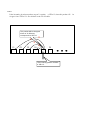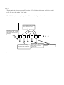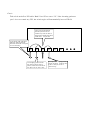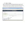
1
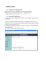
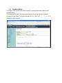
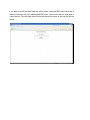
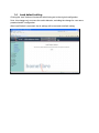
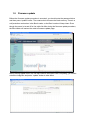
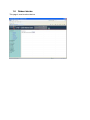
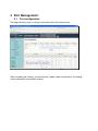
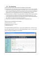
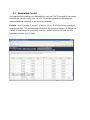
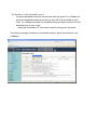
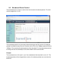
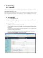
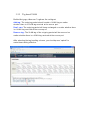
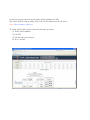
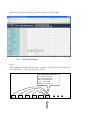
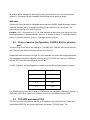
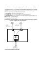
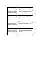
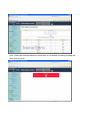
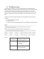
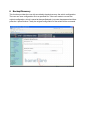
8 Port W eb Smart Sw itch User’s Guide
Purpose
8 Port Web Smart Switch can be configured by web based interface, such as Internet Explore,
Firefox, Safari or other web browser. It provides an interface for the user to set administrator,
port management, VLAN setting, per port counter, trunk setting, QoS setting, security filter,
configuration/ backup/recovery, miscellaneous, log out, and so on.
Prepare to enter the smart switch
Enter the correct user name and password after the login page shows up.
Default IP address: 192.168.2.1
Default user name: admin
Default password; system
N ote : the user name and password fields are case-sensitive.
If you input the incorrect user name and password, the following warning message will
show up.
1. Administrator
1.1 Authentication configuration
This page allows the user to change the user name and the password.
Both User name and password fields allow 15 characters at max.
The legal characters for these fields are “a ~ z”, “A~Z”, “0~9”, “-“, “_”.
1.2 System IP Configuration
This page shows system configuration including the current IP address and sub-net mask
and Gateway.
IP address, Subnet Mask, and Gateway at system IP Configuration web page can be
configured by the user. The smart switch also supports DHCP method to allow the dynamic
IP address allocated by DHCP server.
If you change the setting of this switch and then press, “update”, the “update successfully”
window will show up.
Press “Reboot” button to enter the new web server.
1.3
System status
This page is used to check the status of switch, including Switch MAC address and
software version.
The comment field allows the network administrator to input an easy-to-remember
nickname for this switch. The legal characters are “a~z” and “A~Z”, “_”, “-“, “ +”, “0 ~9”,
excluding special character.
If you want to modify the MAC address of this switch, enter MACIDFix.htm behind the IP
address. Example: http://(IP address)/MACIDFix.htm. Please note that this web page is
case-sensitive. The web page name should be exactly the same as the web link shown
above.
1.4
Load default setting
Clicking the “load” button will make the switch being set to the original configuration.
Note: this change only concerns the switch behavior, excluding the change for user name,
password and IP configuration.
After Load Default is executed, the all settings will be restored to default setting.
1.5
Firmware update
Before the firmware update procedure is executed, you should enter the password twice
and then press “update” button. The smart switch will erase the flash memory. There is a
self-protection mechanism in the Boot Loader, so the Boot Loader will keep intact. Even
though the power is turned off or the cable link fails during the firmware update procedure,
the Boot loader will restore the code to firmware update page.
After pressing update button, the old web code will be erased. After completing, you should
select the image file and press “update” button to take effect.
1.6
Reboot device
This page is used to reboot device.
2 Port Management
2.1
Port configuration
This page allows the user to configure operating mode of the physical port.
After completing the settings, you should press “update” button to take effect. The setting
will be reflected at current status window.
2.2
Port mirroring
The port mirroring function is accomplished by setting the following items.
(a) Destination port: The destination port is the physical port that is set to “copy” the traffic
of the source physical port. Theoretically it’s possible to set more than one destination
port in a network. Actually the port mirroring function will lower the network throughput,
and therefore it’s recommended to set ”only one” destination port in a network.
(b) Monitored packets: (1)Disable: means this function is disabled. (2)RX: means copy the
incoming packets of the selected source port to the selected destination port. (3)TX:
means copy the outgoing packets of the selected source port to the selected destination
port. (4)Rx & Tx: means the combination of Rx and Tx.
(c) Source port: the traffic source that will be copied to the destination port.
Take the following configuration as an example.
(a) Source port: Port 1 ~ Port 4.
(b) Destination Port: Port 5 ~Port 6.
(c) Mirrored packet: Rx.
This means all packets received at port 1 ~port 4 will be copied to port 5, and port 6.Care
should be taken that the more source ports and destination ports is set, the lower
network throughput is available for normal traffic.
2.3
Bandwidth Control
This page allows the setting of the bandwidth for each port. The Tx rate and Rx rate can be
filled with the number ranging from 1 to 255. This number should be multiplied by the
selected bandwidth resolution to get the actual bandwidth.
Example : The TX number of the port1~4 is set to 10, 20, 30, 40 respectively, and Speed
base is set to “low”. The real bandwidth comes from the formula of 32Kbps*10, 32Kbps*20 ,
32Kbps*30 and 32Kbps*40 respectively. After the “update” button is executed, the real
bandwidth will show up in TX fields.
The limitation of the bandwidth control
.
The actual bandwidth should be less than the cable link speed. For 100Mbps link
speed, the bandwidth setting should be less than 196 if the bandwidth is set to
“high". For 10Mbps link speed, the bandwidth setting should be less than 20 if the
bandwidth base is set to “high".
.
Setting the bandwidth to “0" will make the switch running at the full speed.
The warning message will shows up if bandwidth setting is higher than maximum rate
(100Mbps).
2.4
Broadcast Storm Control
The broadcast storm control is used to block the excessive broadcast packets. The valid
number ranges from 1 to 63.
The broadcast packet is only checked at the selected port and the number of broadcast
packets is counted in every time unit. One time unit is 500 us for 10Mbps speed and 5ms for
100Mbps. The excessive broadcast packet will be discarded. For those broadcast packets
incoming from the un-selected port, the switch treats it as the normal traffic.
Example:
The broadcast storm of the port1~ port 6 are enabled and the threshold is set to 10. The
broadcast packets will be dropped when number of broadcast packets are more than the
threshold.
3 VLAN Setting
3.1
VLAN mode
The smart switch supports two VLAN modes, tag based and port based. Only one VLAN
mode can be enabled at one time.
W hen the tag based VLAN is selected, the user can define the handling method of a VLAN
tag to the specified port, including “add a VLAN tag", “ remove a VLAN tag" or “don’t care".
3.2
VLAN Member
3.2.1 Port Based VLAN
The port based VLAN is configured from the point of view of physical port. Each port
should be mapped to a VLAN entry.
Operating procedures
(1) Select a port number and then press “read".
The port member will show up on the table. You can re-assign the VLAN member
for this port.
(2) Select a port number and then select the VLAN member. Press “Update" button
to make the VLAN member effective.
(3) Press “Load default" to restore the default setting for this port. The default
setting select all 8 ports as the member of this VLAN.
3.2.2
Tag based VLAN
On the first page, there are 3 options for each port.
Add tag: The outgoing packet should contain a VLAN tag no matter
whether there is a VLAN tag received at the source port.
Don’t care: The outgoing packet will keep unchanged no matter whether there
is a VLAN tag received at the source port.
Remove tag: The VLAN tag of the outgoing packet will be removed no
matter whether there is a VLAN tag received at the source port.
After selecting the tag hand ling scheme, you should press “upda te" to
make these setting effective.
O n the seco n d page, the user s h o u ld set the VLA N member an d VI D.
The VLA N table is b uilt b y settin g VLA N I D, VLA N n umber an d VLA N in dex.
N ote: VLA N n umber = In dex +1
To set the VLA N table, please follo w the follo w ing pr oced ure.
(1) Select VLA N n umber.
(2) F ill VI D
(3) F ill the in dex for each p ort
(4) Press “u p date”
A fter the VLA N table is u p dated, the VLA N tab le w ill lo o k like this.
3.2.3 Network Scenario
Case 1:
If the incomin g br oadcast packet at p ort 6 contain s a VLA N ID=20, this packet will
be for war ded to P 1 ~ P4, acco rd in g to the VLA N .
If the i nc o mi ng pac k et at port
6 c ontai ns a VID= 20,
the broadc as t pac k et
will be forwarded to P 1
~ P 4. The V LA N
m e mber for VID= 20 is
P 1 ~ P 4.
P1
P2
P3
P4
P5
P6
CASE2:
If the incomin g br oadcast packet at p ort 5 contain s a VID=12, then th is packet w ill
dr o p ped since VI D=1 2 is n ot defined in the VLA N table.
This packet will be dropped
since no VLAN entry
corresponds to VID=12
X
X
X
X
P1
P2
P3
P4
P5
P6
The incoming packet contains
a VID=12.
be
Case 3:
The inco min g br oadcast packet at P 5 co ntains a VI D=20, then th is packet will be for war ded
to P 1 ~ P 4 accor din g to the VLA N table.
The VLA N tag o f each outg oin g packet will be set as the fig ure s h o w n belo w.
The tag of the outgoing pac ket
will be rem ov ed, bec aus e the
action of this port is s et to
"rem ov e tag".
The VID=20 of the inc oming
pac k et will be k ept , bec aus e
the action of this port is s et to
"add tag".
P1
P2
P3
The outgoing pack et will be
the s am e as the inc oming
pac k et, bec ause the action of
this port is s et to "don't c are".
.
P4
P5
P6
The tag of the outgoing pac ket
will be rem ov ed, bec aus e the The inc oming pack et em beds
a VID =20.
action of this port is s et to
"rem ov e tag".
Case 4:
Take a lo o k at the P ort VI D tab le. Both P3 an d P 5 are set to “2 0”. If the inco min g packet at
p ort 3 d oes n ot co ntain any VI D, the sw itch en g ine will automatically insert a VI D=2 0
If t he inc o m in g bro adc as t
pac k et of port 3 does n ot
c ont ains any VI D , t he s w i t c h
engi ne will aut o m at ic ally ins ert
a VI D = 20 t o t his pac k et.
A V AL N t ag (w it h VI D = 2 0)is
add e d t o out goin g pac k et ,
bec a us e t he ac t ion of t his port
is s et t o "ad d t ag".
P1
P2
P3
T h e out goin g pac k et will be
t he s am e as t he inc o m in g
pac k et , bec a us e t he ac t ion of
t his port is s et t o "d o n' t c are".
P4
P5
P6
T h e t ag of t he o ut going p ac k et
w i ll b e rem ov e d, bec a us e t he
ac tion of t his port is s et t o
"re m ov e t ag ".
3.3
Multi-to-1 Setting
Multi-to-1 VLAN is used in CPE side of Ethernet-to-the-Home and is exclusive to VLAN
setting on "VLAN member setting “. W hen VLAN member setting is updated, multi-to-1
setting will be void and vice versa. The “disable port" means the port which will be excluded
in this setting. All ports excluded in this setting are treated as the same VLAN group.
4 Per Port Counter
This page provides port counter for each port. There are 4 groups of statistics in total.
These 4 categories cannot work simultaneously. Once you change the counter category,
the counter will be cleared automatically.
Transmit packet& collision: This category shows the packets outgoing from the switch
and the count of collision.
Receive packet& Transmit packet: This category shows both the received packet
count(excluding the incorrect packet) and the transmitted packet count.
Receive packet & Drop packet: This category shows the number of received valid packet
and the number of dropped packet.
Receive packet & CRC packet: This category shows the received correct packet and
received CRC error.
Refresh: Press “Refresh" button will aggregate the number of the counter for all ports.
Clear: Press “clear" will clear all counters.
5 Trunk setting
This page is used to set trunk group for load balance and auto-backup.
The smart switch supports two trunk group, each trunk consists of 2~4 ports. Trunk hash
algorithm can be selected according to 4 different methods.
Port ID: Among the trunk member ports, the packet will be distributed based on the port ID.
SA: Among the trunk member ports, the packet will be distributed based on the source
MAC address.
DA: Among the trunk member ports, the packet will be distributed based on the destination
MAC address.
DA&SA: Among the trunk member ports, the packet will be distributed based on the XOR
calculation result of the source MAC address and the destination MAC address.
6 QoS setting
6.1
Priority mode
This page allows the user to set the scheduling mode for the TX packets at each port.
All-high-before-low(Strict priority)!"
"
"
All packets will be assigned to either high priority queue (Queue 2) or low priority queue
(queue 1). The packet will not forwarded until the high priority queue is empty.
WRR mode
There are 4 priority queues for Weighted-and-round-robin (W RR) mode. When this mode is
selected, the traffic will be forwarded according to the number set in each queue. The
queue ID has nothing to do with the priority.
Example: If Q1 ~ Q4 are set to 5, 3, 2, 8, then the traffic at the specific port will go out in the
following sequence. 8 packets stored in queue 4, 2 packets in queue 3, 3 packets stored in
queue 2, 5 packets stored in queue 1, 5 packets stored in queue 1 ……
6.2
Class of service Configuration: TOS/DS, 802.1p, physical
port
There are 4 types of CoS for this setting; ie, TCP/UDP port, TOS/DS, 802.1p and physical
port. The user can select more than one item for each port.
Please note that if more than one type of CoS is selected, the switch will arrange the packet
to the assigned queue according the following priority: TCP/UDP port the first, ToS/DS the
second, 802.1p the third and physical port the last.
For 802.1p priority, the following table is used to map the 802.1p field to the priory queue.
Priory Field
Priority Queue
6, 7
Q4
4,5
Q3
0,3
Q2
1,2
Q1
For TOS/DS priority, there are 7 kinds of TOS field can be assigned to 4 different queues. i.e;
6’b001010, 6’b010010, 6’b01110, 6’b100010, 6’b101110, 6’b110000 and 6’b111000.
6.3
TCP/UDP port based COS
The user can select the protocol that will be forwarded as the specified mode. There are 3
user-defined UDP/TCP port groups and many well-known TCP/UDP ports. The
user-defined port number may be a range or a specific number, depending on the mask.
The operating theory for all 4 CoS types can be illustrated by the following figure and table.
TCP/UDP CoS is a global setting for all ports and has no connection with the physical port.
Other CoS types have a connection with the physical port.
(a) Priority Mode: WRR. Q1=4; Q2=2; Q3=8; Q4=1
(b) TCP/UDP CoS: P2 FTP =>Q3; P5 SMTP => Q2; other protocols=Q1
(c) TOS/DS setting: P5 TOS 6’b010010=Q1; P2 TOS 6’b100010=Q3; other TOS=Q4 (d)
802.1p: P5 802.1p = 6; P2 802.1p =1
(e) Physical port: P2=Q4; P2=Q3
According to the rule described above, the CoS will be executed in the following sequence.
TCP/UDP > TOS/DS > 802.1p > Physical port.
SMTP
Client 1
T OS /DS =
6'b010010
802.1p priority
FTP
Client 2
TO S /DS = 6'b100010
802.1p priority = 1
= 6
P 5
P 2
Q1
Q2
Q3
Q4
P 3
FTP Server,
SMTP Server
The actual CoS will behave like this table.
Switch Behavior Observed
Comment
on P 3
8 packets coming from P2;
If TCP/UDP CoS is enabled, the
2 packets coming from P5;
other CoS setting will be ignored.
8 packets coming from P2;
……….
8 packets coming from P2;
If TCP/UDP CoS is disabled, the
4 packets coming from P5;
switch will check TOS/DS CoS.
8 packets coming from P2;
……….
1 packet coming from P2;
If TOS/DS CoS is disabled, the
4 packets coming from P5;
switch will check the 802.1p field.
1 packets coming from P2;
……..
1 packet coming from P2;
If only physical port CoS is enabled,
8 packets coming from P5;
the switch only check the physical
1 packet coming from P2;
port CoS.
……………..
7 Security Filter
7.1
MAC Address Binding
This function provides a method for the administrator to specify the relationship between
the physical port and the MAC address. Only the packet with specified source MAC
address can be forwarded. By specifying the MAC address to each port, the network
administrator can prevent the unauthorized user from accessing the switch. Each port can
correspond to up to 3 MAC addresses.
To activate the port binding function, you should enter the correct MAC address, select the
port number, and set the port binding to “enable" and then press “update".
Note: Setting the multicast address to these fields is not allowed. A warning message will
show up if you do so.
7.2
TCP/UDP port number
By selecting the TCP/UDP port, the network administrator can optionally block some
specific applications. There are two kinds of protocol filter functions. The "forward" function
makes the switch forward the selected protocol and drop other protocols. The "deny"
function makes the switch drop the selected protocol and forward other protocols. The
protocol is checked at the selected secure WAN port. And it should be set at the server
side.
The figure shown below illustrates how this function is applied to the real environment.
Exa mple:
(a) Enable TCP/UDP Filter function.
(b) Select “Allow" rule.
(c) Set port 5 at secure WAN port and select FTP and TELNET as the filtering protocol.
Result:
Physical Port
The Beha vior of Switch
Port 5
TELNET and FTP will be
forwarded. Other protocol will
be discarded.
Other ports
All protocol will be forwarded
as the normal packet.
the
e
8 Backup/Recovery
This function provides the user with a method to backup/recovery the switch configuration.
The user can save configuration file to a specified file. If the user wants to recover the
original configuration, which is saved at the specified path, just enter the password and then
press the “upload" button. Finally the original configuration of the switch will be recovered.
9 Miscellaneous
Miscellaneous setting is used to configure output queue aging time, VLAN stride and IGMP
snooping.
9.1
Output queue aging
This function is used to avoid the poor utilization of the switch. W hen a packet is stored in a
switch for a long time, it will expire from the allowable time defined by the protocol and
become a useless packet. To prevent these packets from wasting the bandwidth, this switch
provide an option for the administrator to enable the queue aging function.
9.2
Stride VLAN
By selecting this function, the switch will forward uni-cast packets to the destination port, no
matter whether destination port is in the same VLAN.
9.3
IGMP Snooping
When this function is enabled, the switch will execute IGMP snooping version 1 and version
2 without the intervention of CPU.
The IGMP report and leave packets are automatically handled by the switch.
Set to IGMP protocol by smart bit and DA set to multicast DA.
10 Logout
The page provides the user to logout web page. Press “accept" to logout.
Press “back" to browse the previous web page.