1
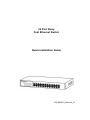
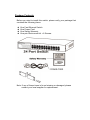
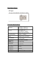
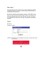
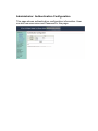
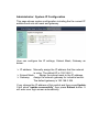
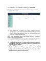
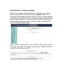
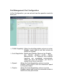
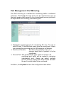
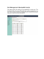
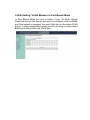
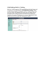
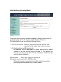
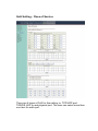
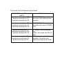
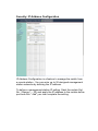
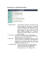
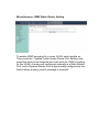
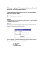
SW-0024F2
24 Port Nway
Fast Ethernet Switch
Quick Installation Guide
SW-0024F2_Manual_V1
FCC Warning
This device has been tested and found to comply with limits for a
Class A digital device, pursuant to Part 2 and 15 of FCC Rules,
These limits are designed to provide reasonable protection against
harmful interference when the equipment is operated in a
commercial environment. This equipment generates and radiates
radio frequency energy and, if not installed and used in accordance
with the user’s manual, it may cause interference in which case
users will be required to correct interference at their own expenses.
CE Warning
This is a Class A product. In a domestic environment, this product
may cause radio interference in which case the user may be required
to take adequate measures.
Introduction
This switch provides 16 10/100M ports. It was designed for easy
installation and high performance in an environment where traffic is
on the network and the number of users increases continuously.
The compact rigid desktop size was specifically designed for small to
medium workgroups. It can be installed where space is limited;
moreover, it provides smooth network migration and easy upgrade to
network capacity.
Package Contents
Before you start to install this switch, please verify your package that
contains the following items:
z
z
z
z
One Fast Ethernet Switch
One Power Cord
One Safety Warranty
One pair Rack-mount kit + 8 Screws
Note: If any of these items is found missing or damaged, please
contact your local supplier for replacement.
Key Features
24 Port 10/100M Nway (Auto-negotiation) Switch
11” Desktop size with metal case
Can be installed in a 19” cabinet by rack-mount kits
Auto-learn of networking configurations
Auto-detect full/half-duplex modes for any port
Dedicated full-duplex 200Mbps bandwidth
Store-and-Forward switching methods
IEEE 802.3x flow control for full-duplex and back-pressure flow
control for half-duplex
z Non-blocking & Non-head-of-line blocking full wire speed
forwarding
z Auto-MDI/MDI-X function for any port
z Smart plug & play
z
z
z
z
z
z
z
z
Front Panel (LEDs)
LED Indicators of 24 Port 10/100M Switch
LED
Power
Status
On
Off
LINK/ACT On
Off
Flashing
10/100M
On
Off
Description
Power is on.
Power is off.
Port is for connection.
No connection.
Data is transmitting or
receiving
Port is on 100M status
Port is on 10M status.
Connections
Switch/Hub to this 24 Port Fast Ethernet Switch
This switch provides automatic crossover detection functionality for
any port. It is simple and friendly to up-link to another switch without
crossover cable.
PC/Other devices to this 24 Port Fast Ethernet Switch
Via a twisted pair cable straight through, this switch can be connected
to PCs, servers and other network devices.
Rear Panel (Power)
AC input
AC input (100~240V/AC, 50~60Hz) UL Safety
Technical Specifications
Standards
Features
Filtering/
Forwarding Rates
Transmission
Media
LED Indicators
Power
Requirement
Power
Consumption
Dimensions
Net Weight
Operating
Temperature
Storage
Temperature
Humidity
Certifications
IEEE 802.3 10BaseT
IEEE 802.3u 100BaseTX
IEEE 802.3x Flow control
Number of Ports: 24
MAC Address: 8K
Buffer Memory: 1.625Mb
Method: Store and Forward
100Mbps port – 148,809pps
10Mbps – 14,880pps
10BaseT Cat. 3, 4, 5 UTP/STP
100BaseTX Cat. 5 UTP/STP
Per Port: LINK/ACT, 10/100M
Per Unit: Power
100~240V/AC, 50~60Hz
10 Watts (Max)
44 x 266 x 160 mm
(HxWxD)
1.40 kg
0 to 55℃
-20 to 90
10 to 90% RH (non-condensing)
FCC Class A, CE
24 Port Nway Fast Ethernet
Web Smart Switch
User’s Manual
User Log In
This part instructs user how to set up and manage the switch
through the web user interface. Please follow the description to
understand the procedure.
At the first, open the web browser, and go to 192.168.2.1 site
then the user will see the login screen. Key in the password to
pass the authentication then clicks the OK. The log in process
is completed and comes out the sign “Password successfully
entered”.
Log in
ID: admin
Password: admin
※Note: It will show error message if you key in wrong user name
or password.
Main Page
- Administrator
Authentication Configuration
System IP Configuration
System Status
Load Default Setting to EEPROM
Firmware Update
Reboot Device
- Port Management
Port Configuration
Port Mirroring
Bandwidth Control
Broadcast Storm Control
- VLAN Setting
VLAN Mode
VLAN Member Setting ( Port Based )
VLAN Member Setting ( Tag Based )
Multi to 1 setting
- Per Port Counter
Counter Category
- QoS Setting
Proirity Mode
Class of Service
- Security
MAC Address Binding
MAC Address Scan ( Scan MAC )
TCP/UDP Filter Configuration
IP Address Configuration
- Spanning Tree
STP Bridge Settings
STP Port Settings
Lookback Detection
- Trunking
Link Aggregation Settings
- Backup/Recovery
- Miscellaneous
Miscellaneous Settings
IGMP Static Router Setting
- SNMP Settings
- Save Settings
- Logout
Administrator: Authentication Configuration
This page shows authentication configuration information. User
can set new username and Password in this page.
Administrator: System IP Configuration
This page shows system configuration including the the current IP
address and sub-net mask and gateway.
User can configure the IP settings, Subnet Mask, Gateway as
below:
¾ IP address: Manually assign the IP address that the network
is using. The default IP is 192.168.2.1
¾ Subnet Mask:
Assign the subnet mask to the IP address.
¾ Gateway:
Assign the network gateway for industrial switch.
The default gateway is 192.168.2.254
If you change the IP address of this switch and then press Update.
It will show “update successfully” then press Reboot button. It
will enter user login screen automatically
Administrator: System Status
This page displays the information about the switch of MAC
address, how many ports it has, system version and. Besides,
users can also fill in up to 15 characters in the Comment, Contact
and Location field for note.
¾ MAC Address:
¾
¾
¾
¾
¾
Displays the unique hardware address
assigned by manufacturer (default).
Number of Ports: Displays number of ports in the switch.
Comment: Users can fill in up to 15 characters in this field.
System Version: Displays the switch’s firmware version.
Idle Time Security:
User can set the time security. When
user leave the computer for a moment,
the software will auto logout or back to
the last display.
And then click Update button.
Administrator: Load Default Setting to EEPROM
Clicking the Load button will make the switch being set to the
original configuration.
※ Note: It exclude to change user name, password and IP
configuration. If you want to restore default setting including
IP and user name password, then you can press the reset
button for hardware base reset.
More detail information about Load Default Setting - Hardware
Base is described as following.
The purpose of this function is to provide a method for the network
administrator to restore all configurations to the default value.
(1) To activate this function, the user should follow the following
procedures. Press the “Load default” button for 3 seconds until
you see the LED blinking.
(2) When LED starts blinking, it means the CPU is executing the
“load default” procedure. You can release the button now.
After completing this procedure, all the factory default value
will be restored. It includes the IP address, the user name, the
password and all switch configurations.
Administrator: Firmware Update
Before the firmware update procedure is executed, you should
enter the password twice and then press Update button. The
smart switch will erase the flash memory. There is a self-protection
mechanism in the Boot Loader, so the Boot Loader will keep intact.
Even though the power is turned off or the cable link fails during
the firmware update procedure, the Boot loader will restore the
code to firmware update page.
After pressing Update button, the old web code will be erased.
Then you can select the image file and press “update” button to
update the firmware you need.
Administrator: Reboot Device
Click Confirm button to reboot the device.
Note: The reboot is for software base instead of hardware base.
Port Management: Port Configuration
In Port Configuration, you can set and view the operation mode for
each port.
¾ TX/RX Capability: When the Auto-Negotiation column is set as
Disable, users have to set this column as
Enable or Disable.
¾ Auto-Negotiation: Enable and Disable. Being set as ‘Enable’,
the
Speed, Duplex
mode,
Pause,
Backpressure, TX Capability and Address
Learning are negotiated automatically.
When you set it as ‘Disable’, you have to
assign those items manually.
¾ Speed:
When the Auto-Negotiation column is set as
Disable, users have to set the connection speed
to the ports ticked.
¾ Duplex:
When the Auto-Negotiation column is set as
Disable, users have to set the connection mode in
Half/Full to the ports ticked.
¾ Pause: Flow Control for connection at speed of 10/100Mbps in
Full-duplex mode.
¾ Backpressure:
Flow Control for connection at speed of
10/100Mbps in Half-duplex mode.
¾ Addr. Learning: When the Auto-Negotiation column is set as
Disable, users have to set this column as
Enable or Disable.
¾ Select Port No.: Tick the check boxes beside the port
numbers being set.
¾ Click Update to have the configuration take effect.
¾ Current Status: Displays current port status.
¾ Setting Status:
Displays current status.
Click Update to make the configuration effective.
Port Management: Port Mirroring
The Port mirroring is a method for monitoring traffic in switched
networks. That Traffic through ports can be monitored by any of
the ports means traffic goes in or out monitored (source) ports will
be duplicated into mirroring (destination) port.
¾ Destination (mirroring) port for monitoring Rx only, Tx only or
both RX and TX traffic which come from the source port. Users
can connect the mirroring port to LAN analyzer or Netxray.
¾ Monitored Packets:
Pull down the selection menu to
choose what kind of packet is to be
monitored.
¾ Source Port: The ports that the user wants to monitor. All
monitored port traffic will be copied to mirroring
(destination) port. Users can select multiple
source ports by ticking the check boxes beneath
the port number label to be monitored.
And then, click Update to have the configuration take effect.
Port Management: Bandwidth Control
This page allows the setting of the bandwidth for each port. The
TX rate and Rx rate can be filled with the number ranging from 1 to
255. This number should be multiplied by the selected bandwidth
resolution to get the actual bandwidth.
Port Management: Broadcast Storm Control
The switch implements a broadcast storm control mechanism.
Tick the check boxes to have them beginning to drop incoming
broadcast packets if the received broadcast packet counts reach
the threshold defined. Each port’s broadcast storm protection
function can be enabled individually by ticking the check boxes.
The broadcast packet is only checked at the selected port and the
number of broadcast packets is counted in every time unit. One
time unit is 500 us for 10Mbps speed and 5ms for 100Mbps. The
excessive broadcast packet will be discarded. For those broadcast
packets incoming from the un-selected port, the switch treats it as
the normal traffic.
¾ Threshold:
Type in the threshold in the range between 1 and
63 to limit the maximum byte counts, which a port
can send or receive in a period of time.
¾ Enable Port: Having ticked the boxes, the port will stop
transmitting or receiving data when their sending
byte counts or receiving byte counts reach the
defined threshold.
Click Update to have the configuration take effect.
VLAN Setting: VLAN Mode
You may select the VLAN Mode of the switch.
Port-Based Mode
Port-based VLAN is for separating traffic only on this single switch.
There is no handover of network traffic within VLAN groups to
other switches.
Tag Baesd Mode
For the handover to other switches use Tag Based VLAN. In
VLAN Mode you can switch from Tag to Port Based VLAN. Port
Based VLAN is the default mode.
VLAN Setting: VLAN Member in Port Based Mode
In Port Based Mode you see a matrix of your 16 Ports. Simply
select the port on top screen you want to configure, click on Read,
and then select or deselect the ports that are on the same VLAN
group. In this configuration mode you do not need to worry about
defining VLAN groups and VLAN IDs.
VLAN Setting: VLAN Member in Tag Based Mode
Add a VLAN:
Enter a VID, select the VLAN member and click
the VID source port and then enter a group name.
Finally press “add” button to send this command.
The VLAN will be added to the list.
Delete a VLAN:
Select a VID and press “Delete” to remove a
VLAN.
Modify a VLAN:
Select a VID which you want to modify. After
the web page shows up, select the VLAN
member and VID source port and then press
“update”.
Add a VLAN Group
Step 1: Select / De-Select the VLAN ID
Step 2: Select / De-Select VID source corresponding to this VID
Step 3: Press “ Update “
VLAN Setting: Multi to 1 Setting
Multi to I VLAN is used in CPE side of Ethernet-to-the-Home and
is exclusive to VLAN setting on VLAN Member Setting. When
VLAN member Setting is updated, multi to 1 setting will be void
and vice versa. The disable port means the port which will be
excluded in this setting. All ports excluded in this setting are
treated as the same VLAN group. In a normal Tag Based VLAN
network you will not need this configuration option.
Per Port Counter: Counter Category
This page provides port counter of each port. There are 4
categories: Receive Packet & Transmit Packet/ Transmit &
Collision / Receive Packet & Drop /Receive & CRC error. Once
you change the counter category, the counter will be cleared
automatically.
¾ Transmit packet & Receive packet:
This category shows both the received packet count
(excluding the incorrect packet) and the transmitted packet
count.
¾ Collision Count & Transmit packet:
This category shows the packets outgoing from the switch
and the count of collision.
¾ Drop packet & Receive packet:
This category shows the number of received valid packet
and the number of dropped packet.
¾ CRC packet & Receive packet:
This category shows the received correct packet and
received CRC error.
¾ Clear: Press “clear” will clear all counters.
¾ Refresh:
Press “Refresh” button will aggregate the number
of the counter for all ports.
QoS Setting: Priority Mode
There are three priority modes available to specify the priority of
packets being serviced. Those include First-in-First-out,
All-High-Before-Low, and-Weight-Round-Robin.
¾ First-In-First-Out: Packets are placed into the queue and
serviced in the order they were received.
¾ All-high-before-low(Strict priority):
All packets will be assigned to either high priority queue
(Queue 2) or low priority queue (Queue 1). The packet on
the low priority queue will not be forwarded until the high
priority queue is empty.
WRR mode:
There are 4 priority queues for
Weighted-and-round-robin (WRR) mode:
When this mode is selected, the traffic will be forwarded
according to the member set in each queue.
QoS Setting : Class of Service
There are 4 types of CoS for this setting; ie, TCP/UDP port,
TOS/DS, 802.1p and physical port. The user can select more than
one item for each port.
Please note that if more than one type of CoS is selected, the
switch will arrange the packet to the assigned queue according the
following priority: TCP/UDP port the first, ToS/DS the second,
802.1p the third and physical port the last.
For 802.1p priority, the following table is used to map the 802.1p
field to the priory queue.
Priory Field
Priority Queue
6, 7
4,5
0,3
1,2
Q4
Q3
Q2
Q1
For TOS/DS priority, there are 7 kinds of TOS field can be
assigned to 4 different queues. i.e; 6’b001010, 6’b010010,
6’b01110, 6’b100010, 6’b101110, 6’b110000 and 6’b111000.
TCP/UDP port based COS
The user can select the protocol that will be forwarded as the
specified mode. There are 3 user-defined UDP/TCP port groups
and many well-known TCP/UDP ports. The user-defined port
number may be a range or a specific number, depending on the
mask.
The operating theory for all 4 CoS types can be illustrated by the
following figure and table.
TCP/UDP CoS is a global setting for all ports and has no
connection with the physical port. Other CoS types have a
connection with the physical port.
(a) Priority Mode:
(b) TCP/UDP CoS:
WRR. Q1=4; Q2=2; Q3=8; Q4=1
P2 FTP =>Q3; P5 SMTP => Q2; other
protocols=Q1
(c) TOS/DS setting: P5 TOS 6’b010010=Q1; P2 TOS
6’b100010=Q3; other TOS=Q4
(d) 802.1p:
P5 802.1p = 6; P2 802.1p =1
(e) Physical port: P2=Q4; P2=Q3
According to the rule described above, the CoS will be executed in
the following sequence.
TCP/UDP > TOS/DS > 802.1p > Physical port.
The actual CoS will behave like this table.
Switch Behavior Observed
on P 3
8 packets coming from P2;
2 packets coming from P5;
8 packets coming from P2;
If TCP/UDP CoS is enabled,
the other CoS setting will be
ignored.
8 packets coming from P2;
4 packets coming from P5;
8 packets coming from P2;
If TCP/UDP CoS is disabled,
the switch will check TOS/DS
CoS.
1 packet coming from P2;
4 packets coming from P5;
1 packets coming from P2;
If TOS/DS CoS is disabled,
the
switch will check the 802.1p
field.
If only physical port CoS is
enabled, the switch only
check the physical port CoS.
1 packet coming from P2;
8 packets coming from P5;
1 packet coming from P2;
Comment
Security: MAC Address Binding
¾ Port No:
¾
¾
¾
¾
Displays the port number being assigned the
MAC addresses.
MAC Address:
Users can assign up to 3 MAC addresses to
the port.
Read: Pull down the selection bar to choose a port number
and click the read button to show the MAC addresses
bound with the port or modify the MAC addresses.
Select Port: Pull down the selection menu bar to choose a port
number to be set.
Binding:
Enable or disable the binding function.
Click Update to have the configuration take effect.
Security : Scan MAC
Scan MAC shows the MAC address learned by the switch, To add
a MAC address to the Static MAC address list, select the port no
and it will show the MAC address of the identified address.
Security: TCP/UDP Filter Configuration
By selecting the TCP/UDP port, the network administrator can
optionally block some specific applications. There are two kinds of
protocol filter functions.
Allow Mode
The ”forward” function makes the switch forward the selected
protocol and drop other protocols.
Deny Mode
The ”deny” function makes the switch drop the selected protocol
and forward other protocols. The protocol is checked at the
selected secure WAN port. And it should be set at the server side.
The figure shown above illustrates how this function is applied to
the real environment.
Note: The TCP/UDP Filter’s user-defined Port-Range is in
QoS Setting’s Class of Service
Security: IP Address Configuration
IP Address Configuration is a feature to manage the switch from
a remote station . You can enter up to 30 designed management
station networks by defining the IP address.
To define a management station IP setting. Selet the certain Set
No. ( Range 1 – 32) and apply the IP address to the certain define
port and click “ Add” you man complete the setting.
Global Setting
There are 2 range that you may choice from the Globle
Setting :
Check Source IP adder or Destin IP adder as
Also, there are 4 Rule that you can define the setting :
IP mismatch can pass
IP match can pass
IP match and port match pass
IP match and port mismatch can pass
Spanning Tree: STP Bridge Setting
¾ Bridge Priority:
This parameter configures the spanning tree
priority globally for this switch. The device
with the highest priority becomes the STP
root device. However, if all devices have the
same priority, the device with the lowest
MAC address will then become the root
device. Number between 0 - 61440 in
increments of 4096. Therefore, there are 16
distinct values.
¾ Hello Time: Interval (in seconds) at which the root device
transmits a configuration message (BPDU frame).
Number between 1-10 (default is 2).
¾ Max Age:
The maximum time (in seconds) a device can wait
without receiving a configuration message before
attempting to reconfigure. That also means the
maximum life time for a BPDU frame. Number
between 6-40 (default is 20).
¾ Forward Delay: The maximum time (in seconds) the root
device will wait before changing states (i.e.,
discarding to learning to forwarding).
Number between 4 – 30 (default is 15)
Spanning Tree: STP Port Settings
¾ Port No:
The port ID. It cannot be changed. Aggregations
mean any configured trunk group.
¾ Root Path Cost: This parameter is used by the STP to
determine the best path between devices.
Therefore, lower values should be assigned
to ports attached to faster media, and higher
values assigned to ports with slower media.
Set the RSTP path cost on the port. Number
between 0 - 200000000. 0 means auto
generated path cost.
¾ State: Show the current port state includes designated port,
root port or blocked port.
¾ Status: Show the current port status includes forwarding,
disable etc.
Spanning Tree: Loopback Detection Settings
This feature is to detect each port, to see any cable loop occurred
on a single port. When Transmit a data packet from one port and
also Receive same data packet from the same port, it is caused by
the cable which connect to the port has a loop (i.e. TX lines tie
together with RX lines), This switch will disable the port.
Trunking
This page is used to set trunk group for load balance and
auto-backup.
The smart switch supports two trunk group, each trunk consists of
2~4 ports. Trunk hash algorithm can be selected according to 4
different methods.
Port ID:
Among the trunk member ports, the packet will be
distributed based on the port ID.
SA:
Among the trunk member ports, the packet will be
distributed based on the source MAC address.
DA:
Among the trunk member ports, the packet will be
distributed based on the destination MAC address.
DA&SA: Among the trunk member ports, the packet will be
distributed based on the XOR calculation result of the
source MAC address and the destination MAC
address.
Backup/Recovery
This function provides the user with a method to backup/recovery
the switch configuration. The user can save configuration file to a
specified file. If the user wants to recover the original configuration,
which is saved at the specified path, just enter the password and
then press the “upload” button. Finally the original configuration of
the switch will be recovered.
Miscellaneous: Miscellaneous Settings
Miscellaneous setting is used to configure output queue aging
time, VLAN stride and IGMP snooping.
¾ Output queue aging:
This function is used to avoid the poor
utilization of the switch. When a packet
is stored in a switch for a long time, it
will expire from the allowable time
defined by the protocol and become a
useless packet. To prevent these
packets from wasting the bandwidth,
this switch provide an option for the
administrator to enable the queue
aging function.
¾ VLAN Striding:
By selecting this function, the switch will
forward uni-cast packets to the destination
port, no matter whether destination port is in
the same VLAN.
¾ IGMP Snooping: When this function is enabled, the switch will
execute IGMP snooping version 1 and
version 2 without the intervention of CPU.
The IGMP report and leave packets are
automatically handled by the switch.
Miscellaneous: IGMP Static Router Setting
To enable IGMP snooping for a given VLAN, select enable on
Then press the “ Update” button under Router Port Setting, and
select the ports to be assigned as router ports for IGMP snooping
for the VLAN. A router port configured manually is a Static Router
Port, and a Dynamic Router Port is dynamically configured by the
Switch when a query control message is received.
SNMP Settings
The SNMP Setting allows you to quick enable/ disable the SNMP
function and configure the SNMP Community name.
The default SNMP setting is disabled. Click Enabled, enter
community names to configure community Settings.
Community Settings
Community Name: A community name that acts like a password
and permints access to the SNMP protocol.
Public: Read-Only privilege allows authorized management
stations to retrieve MIB objects.
Private : Read /write privilege allows authorized management
stations to retrieve and modify MIB OBJECTS.
SNMP Setting:
In support of SNMP version 1, the
Web-Smart Switch accomplishes user
authentication by using Community Settings
that function as passwords. The remote user
SNMP application and the Switch SNMP
must use the same community string. SNMP
packets from a station that are not
authenticated are ignored.
System Description:
System Contact:
System Location:
A Description assigned to the switch
system
Specifies the system Contact
Specifies the system Location
Logout
The administrator has write access for all parameters governing
the onboard agent. User should therefore assign a new
administrator password as soon as possible, and store it in a safe
place.
When you forgot your IP or password, please use the reset
button for the factory default setting?
Please take the following steps to reset the Web Smart Switch
back to the original default:
Step 1:
Turn on the Web Smart Switch
Step 2:
Press and hold the reset button continuously for 5 seconds and
release the reset button.
Step 3:
The switch will reboot for 20 seconds and the configuration of
switch will back to the default setting.
Key in the user ID and the password to pass the authentication;
the user ID and the password are “admin”
IP: 192.168.2.1
ID: admin
Password: admin