1
User’s guide VIPpanel
V1.1
Hanspeter Züger
El.-Ing. ETH
&
Mark John Butcher
BSc (Hons) MPhil MIEE
M.J.Butcher Consulting
Bahnhofstrasse 13 5507 Mellingen
Switzerland
www.mjbc.ch
1)
INTRODUCTION .............................................................................................. 4
2)
COMMUNICATION .......................................................................................... 5
How does my application communicate with the VIPpanel?.......................................................... 6
3)
OUR HARDWARE ........................................................................................... 8
4)
INSTALLATION OF THE DEMO-PROGRAM ON THE PC ............................. 8
Overview of the Demo-Program......................................................................................................... 8
5)
OPERATION OF THE VIPPANEL ................................................................... 9
Creation or modification of a front panel.......................................................................................... 9
Opening a design in the front panel simulator................................................................................. 9
Drawing a new front panel.................................................................................................................. 9
Defining keys ..................................................................................................................................... 10
Defining LEDs .................................................................................................................................... 11
Adding an LCD................................................................................................................................... 11
Saving your new design ................................................................................................................... 11
Setting the communication parameters.......................................................................................... 12
Serial interface ...................................................................................................................................................12
Ethernet LAN ....................................................................................................................................................12
Communication monitor ................................................................................................................... 13
Trace-window..................................................................................................................................... 14
LCD Control Panel............................................................................................................................. 14
Test input ...........................................................................................................................................................15
Display commands.............................................................................................................................................15
Defining characters............................................................................................................................................15
6)
OPERATING PRINCIPAL OF THE VIPPANEL ..............................................16
Treating of key presses .................................................................................................................... 16
Control of the LCD............................................................................................................................. 16
Reset and initialisation ..................................................................................................................... 16
7)
WHAT DO I DO WHEN MY DESIGN IS COMPLETE?...................................17
8)
APPENDIX A: FORMAT OF THE TELEGRAMS ............................................18
Format of the telegrams.................................................................................................................... 18
Telegrams for reset and configuration............................................................................................ 19
Telegrams for LCD control ............................................................................................................... 22
Telegrams for LED-control ............................................................................................................... 25
Key settings and responses............................................................................................................. 28
Telegrams for Buzzer control........................................................................................................... 29
Overview of telegrams ...................................................................................................................... 30
9)
APPENDIX B: COMMUNICATION OVER ETHERNET / TCP/IP....................31
Reset ................................................................................................................................................... 31
Establishing contact ......................................................................................................................... 31
Keep alive ........................................................................................................................................... 32
UDP Protocol ..................................................................................................................................... 32
Ethernet / Internet with VIPpanel and the Demo-Application ....................................................... 33
10/100M LAN operation..................................................................................................................... 33
10)
APPENDIX C TIPS FOR THE CONTROL OF LCDS ......................................34
User definable characters................................................................................................................. 34
Shift mode .......................................................................................................................................... 35
User’s manual
M.J.Butcher Consulting
solution engineering
1) Introduction
The VIPpanel is a Windows program which allows a complete front panel with keys, LEDs
and LC-Display to be simulated. The VIPpanel enables in addition the creation and
simulation of your own front panel designs and it can be used as input-/output device for
connection to your own hardware and embedded applications. The communication between
your hardware/application and the VIPpanel takes place either via the serial port or Ethernet
LAN interface of the PC.
The VIPpanel design, the number of keys and their sizes, the number of LEDs and the type
of LCD display are all freely definable.
Based on your design data we can deliver the corresponding hardware in a short time.
During this time, the VIPpanel can be used for the continuation or completion of the
application development....
New in the Version V1.1:
• New command enabling the setting of the text position and writing text in one
operation
• Improved network support when multiple users are accessing the device
• Keys and LEDs can be repositionen using the mouse
• The VIPpanel Software available in both english and German
VIPpanel User’s manual V1.1 12.8.2005
4/35
www.mjbc.ch
User’s manual
M.J.Butcher Consulting
solution engineering
2) Communication
The VIPpanel simulates the behaviour of a front panel 1:1 and communicates with the
application via a defined interface using a protocol which has been optimised for the job. The
protocol is suitable for both direct serial connections and networks. For differing
requirements, the protocol can be configured for simple operation [when there are no high
levels of security necessary] or robustness [for high transmission security in harsh
environments].
You application can either operate on a Windows PC or directly on your target hardware. In
the first case the application communicates over a defined software interface with the
VIPpanel and in the latter via the PC serial interface or Ethernet/LAN. The protocol remains
basically the same.
The communication is based on a simple serial master-slave operation, where the
application is the master and the VIPpanel is the slave. Commands are individually
acknowledged by the on VIPpanel completion.
Events at the VIPpanel (for example changes of key states) are sent automatically to the
application or the state can be polled.
The format of the telegrams is detailed in Appendix A.
VIPpanel User’s manual V1.1 12.8.2005
5/35
www.mjbc.ch
User’s manual
M.J.Butcher Consulting
solution engineering
How does my application communicate with the VIPpanel?
There are various possibilities to communicate with the VIPpanel but basically 2 procedures:
If your application operates under Windows, it can communicate with the VIPpanel
directly via DLL library functions. You can find information in the “Application Note:
Demo-project for the VIPpanel“. There you can learn how an embedded
development can be possible using for example VisualStudio and we can advise
you personally if required.
VIPpanel Demo
[Simulation mode of operation] The application and the VIPpanel run on a PC and
communicate with each other via a software interface
VIPpanel User’s manual V1.1 12.8.2005
6/35
www.mjbc.ch
M.J.Butcher Consulting
solution engineering
User’s manual
With the VIPpanel configured in interface mode, it can control a standard front
panel in parallel mode of operation (depending on the type, either via the serial
interface or Ethernet/LAN).
VIPpanel Demo
Standardfrontplatte
VIPpanel Demo
[Parallel mode of operation] The application and the VIPpanel run on a PC and
communicate with each other via a software interface. An external front panel is controlled in
parallel with the VIPpanel
In case you have a hardware which is to communicate with the VIPpanel, simply
send us your VIPpanel design and we will configure the project free of charge to
operate with your design and your target.
!
VIPpanel Demo
"
#
[Hardware mode of operation] Application runs on the target hardware
VIPpanel User’s manual V1.1 12.8.2005
7/35
www.mjbc.ch
User’s manual
M.J.Butcher Consulting
solution engineering
3) Our Hardware
As well as the VIPpanel we supply several multi-functional standard front panels. Depending
on the type, each is equipped with serial and/or Ethernet LAN interfaces. The front panels
use the same communication protocol as the VIPpanel and can be operated in parallel to the
VIPpanel (see parallel mode of operation above).
To learn how to configure the VIPpanels for the parallel mode of operation see the chapter
„Setting the communication parameters“.
4) Installation of the Demo-Program on the PC
The Demo-Program for the VIPpanel is delivered either as VisualStudio Projekt or as
executable (with installation program). Should you prefer to use the executable simple start
the installation program and follow the guide.
The VisualStudio project can be compiled and operated with Microsoft VisualStudio.
This Demo-program starts the VIPpanel and shows several capabilities of the LCD display
using a simple menu controlled interface. The VisualStudio project allows modifications to be
made to the application as well as new front panel creations to be made. Without the
VisualStudio project it is not possible to modify the Demo-program but the VIPpanel can be
used without limits to create and test new designs.
Overview of the Demo-Program
The Demo-program is based on pre-defined front panel designs with 2 or 4 line LCD
displays, joystick or matrix keyboard and also 3 bi-colour LEDs.
In addition, the application window shows a switch and an analogue voltage control; these
elements are part of the demo-application and not the front panel.
Notes concerning the protocol settings used by the demo-program (see the protocol
description for more details):
•
The Demo-program operates in event mode (not polling mode) since this is the
preferred and most efficient mode.
•
The application sends acknowledgements in response to key events.
•
Messages are transmitted with as sequence number and a check sum [CRC-16 in
LAN mode].
The last 3 settings ensure a very secure connection and are not always necessary. The
Demo-application can be configured to operate with other protocol settings for test purposes
(see the instructions to the demo-application).
By changing the inputs in the application window and pressing keys on the VIPpanel, a
number of different functions can be tested. You can also modify the design of the front panel
as you wish and experience how your own design then becomes operational.
The operation of the Demo-application is described in detail in the document „VIPpanelDemo-Application“.
We hope that you enjoy the test!
VIPpanel User’s manual V1.1 12.8.2005
8/35
www.mjbc.ch
User’s manual
M.J.Butcher Consulting
solution engineering
5) Operation of the VIPpanel
Creation or modification of a front panel
The creation of a new design consists essentially of 5 steps. In case you want to modify an
existing design, various steps can be left out:
Design of the front panel including keys in a drawing program
Import of the design in the front panel simulator (VIPpanel)
Definition of key press areas and their corresponding key codes (IDs)
Definition of LEDs and their corresponding LED codes (IDs)
Choice and positioning of an LCD display
In the following description it is assumed that you begin with one of the existing front panel
designs.
Opening a design in the front panel simulator
When the VIPpanel starts it automatically loads the last used design. You can however chice
from a number of designs delivered with the VIPpanel. Simply select „File | Open design“
and choose a design (with *.VIP extension).
A design includes the front panel as well as all elements such as LCD, keys and LEDs.
Drawing a new front panel
You can very simply create your new front panel design using your favourite drawing
program (for example PhotoShop, PaintShop) or with the simple drawing program “Paint”
which is a part of the standard Windows installation. Alternatively existing designs can be
used as templates and modified as desired.
The front panel ist displayed in its real size by the VIPpanel and it is therefore important that
the Bitmap is created with the correct size. If, for example, you wish to create a front panel
with the dimensions 135mm x 70mm, you should create the drawing with these dimensions –
Paint allows this for example using “picture | attributes…”
Draw your new front panel with your desired colours, patterns and fonts and add drawings of
keys in their desired sizes and colours. You can set frames for the positioning of LCD display
and LEDs if you wish but this is not absolutely necessary since they will b eadded in the
VIPpanel later.
Alternatively you can modify an existing design by exporting it to a Bitmap (File | Export
front panel (BMP)…), editing it in a drawing program and finaly re-importing it to the
VIPpanel (File | Import front panel (BMP)…).
When the front panel is imported, all elements such as keys, LEDs and LCD remain in the
design. Should you wish to start with a fresh design it is best to use (File | New design…),
which deletes all design elements and start with a fresh sheet.
VIPpanel User’s manual V1.1 12.8.2005
9/35
www.mjbc.ch
User’s manual
M.J.Butcher Consulting
solution engineering
Defining keys
So that the VIPpanel knows where the keys are in an imported design these must first be
defined. You can add up to 256 keys.
Activate the item ‚Define Keys [F6]‘ in the ‘Edit‘ Menu.
Draw a key by clicking the left mouse key while holding the SHIFT key down and
pulling the rectangle to represent the active key press area. A dialog box is
automatically opened where the parameters of the key are visible and the key ID can
be modified if required. The parameters are:
Name: This is the object name (eg. KEY 1), which may be used later for add in
context sensitive support such as help text for the key.
Tool Tip: Add a Tool Tip fort he key which will be displayed when the user holds the
mouse over it. For example – “Press this key to start program X “.
ID: Every key requires a key ID which can have the value from 0 to 255. It is best to
start from 0 and defin eth emost often used keys in the range 0..6. When the key is
pressed, its ID is sent to the application. ID 0 = 0x01, ID 1 = 0x02, ID 2 = 0x04, ID 3
= 0x08 etc. until ID 255 =
0x8000000000000000000000000000000000000000000000000000000000000000.
You will however see in the protocol description that such long values do not
actually have to be transmitted!
The next lowest available ID is automatically suggested for each new key by the
dialog and this can be accepted or modified as required.
Dimension / Position: the exact size and position of the key press area is displayed.
This procedure is repeated for each key in the design.
You can perform a right mouse click on a key at any time to reactivate its characteristic
dialog and modify parameters or delete the key if desired.
A key can be repositionen by dragging with the mouse. First show objects in the design [F4]
and press and hold the SHIFT button. Click once on the key to be moved to lock it to the
mouse. Move it to its new position and click again to lock it to the new position.
Note: All objects in the design, including keys, can be displayed by using command Show
Objects [F4] in the Edit menu. The objects can be hidden by using the command Hide
objects [F5] in the Edit menu.
VIPpanel User’s manual V1.1 12.8.2005
10/35
www.mjbc.ch
User’s manual
M.J.Butcher Consulting
solution engineering
Defining LEDs
You can add up to 256 LED IDs to your front panel design. These LEDs can then be
controlled by using protocol commands. The procedure is very similar to the definition of
keys:
Activate the item ‚Define LEDs [F7]‘ in the ‘Edit‘ Menu.
Draw an LED by clicking the left mouse key at the centre of the LED location while
holding the SHIFT key down and pulling the radius of the circle to represent the LED
circumference. A dialog box is automatically opened where the parameters of the LED
are visible and the LED ID(s) can be modified if required:
Follow the instructions for the definition if keys and define in addition the LED colour
when its ID is in the active (logical 1) and inactive (logical 0) state.
Dual colour LEDs can be defined – in which case 2 IDs are necessary. In this case 4
colours are possible, corresponding to the 4 possible state combinations of the two IDs.
For example ‘00’ = off; ’01’ = green, ‘10’ = red, ‘11’ = orange.
An LED can be repositionen by dragging with the mouse. First show objects in the design
[F4] and press and hold the SHIFT button. Click once on the LED to be moved to lock it to
the mouse. Move it to its new position and click again to lock it to the new position.
Note: All objects in the design, including LEDs, can be displayed by using command Show
Objects [F4] in the Edit menu. The objects can be hidden by using the command Hide
objects [F5] in the Edit menu.
Adding an LCD
To add an LCD display to the design, simply select a type from the LCD menu and position it
to the required location. The available LCDs can be found in the folder VIPdesigns\LCDs and
have the extension *.LCD. Please contact us if you require types from additional
manufacturers.
Saving your new design
When you are satisfied with your VIPpanel design you can save it using either File | Save
Design‘ or. ‚File | Save design as..’ to a *.VIP file. This file can then be shared or
exchanged with other VIPpanel users.
Send your design to us if you require an offer for the delivery of corresponding hardware. In
addition this design file is required if you would like to control the VIPpanel either over the
serial interface or Ethernet LAN interface from your embedded hardware – in this case we
will send you a specially configured program - with out charge – for this use.
VIPpanel User’s manual V1.1 12.8.2005
11/35
www.mjbc.ch
User’s manual
M.J.Butcher Consulting
solution engineering
Setting the communication parameters
The communication parameters are needed if the VIPpanel is to be used either in the
parallel mode of operation with an external front panel.
The settings are defined in the menu ‚Communication | Communication settings…‘ For
use with our standard front panel the correct settings can be found in the corresponding
product specification.
Serial interface
The transmission speed (Baud rate), parity and number of Stopp bits can be set and the
COM interface of the PC selected. The VIPpanel-protocol does not require flow control at the
RS-232 level.
Ethernet LAN
Certain front panels support a connection via an Ethernet LAN or the Internet. The IP
address of the hardware and the port number it uses must be set here.
Warning: Firewalls can block certain IP / Port combinations. If there are firewalls between the
LAN capable front panel/ VIPpanel and the appliciation, their settings must be verified. We
can advise you in this case if you do encounter any difficulties.
See appendix B for more details.
VIPpanel User’s manual V1.1 12.8.2005
12/35
www.mjbc.ch
M.J.Butcher Consulting
solution engineering
User’s manual
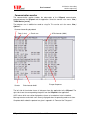
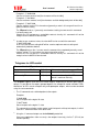
Communication monitor
The communication monitor enables the observation of the VIPpanel communication
protocol between the VIPpanel and the application. Select the monitor in the menu ‘View |
TX/RX Monitor [on/off]‘.
The telegrams can in addition be saved to a log file. This can be set in the menu ‚View |
Options…
Command according to protocol
Date (in hex)
Counter
Check sum
ACK character (0x06)
Escape Sequence
End character 0x0d
The left side of the window shows all telegrams from the application to the VIPpanel. The
right side shows the corresponding telegrams from the VIPpanel to the application.
ASCII values which can not be displayed are shows as hexadecimal value in brackets.
Message counters and check sums are only displayed when the operating mode uses them.
Complete details about the protocol are given in appendix A: “Format of the Telegrams”.
VIPpanel User’s manual V1.1 12.8.2005
13/35
www.mjbc.ch
User’s manual
M.J.Butcher Consulting
solution engineering
Trace-window
A trace windows with debugging messages can be activated using ‚View | Trace‘. The
information can aid in resolving problems with the VIPpanel and also problems caused by
your own application.
The trace messages can optionally be saved to a file by activating it in the menu ‚View |
Options’
LCD Control Panel
The LCD Control Panel is a further, very comfortable tool to help creating your own
applications. It can be activated in the menu ‘View | LCD Control panel’
When the LCD Control Panel is running, the LCD can be controlled directly.
Built into the LCD Control Panel is a guide to the LCD command set and a viewer of the
present LCD font set. This allows you to concentrate on preparing your application without
the need to consult data sheets.
Using the LCD Control Panel you can experiment with the capabilities of the LCD display
without needing to first make a special application to do this. This allows all necessary
command sequences first to be evaluated before they are committed to code.
Use the LCD Control Panel in conjunction with the RX/TX monitor to get to know the
command protocol and the LCD reaction.
VIPpanel User’s manual V1.1 12.8.2005
14/35
www.mjbc.ch
User’s manual
M.J.Butcher Consulting
solution engineering
Test input
This is where text is entered to be sent to the LCD. The text appears at the present cursor
position (in case this is outside of the LCD visible area it will also no be seen). Characters
which can not be entered from the keyboard can be entered using the C-code convention
\xXX. For example the character with the ASCII code 1 can be entered as \x01.
Tip: If you wish to send a back slash (\) to be displayed in the LCD display, enter it twice ‘\\’
but be aware that most LCD font sets have a different symbol to the back slash at this
position in the font table!!
Display commands
This is where raw LCD commands can be entered – as defined by the command set of the
LCD. The entry is in hexadecimal form without leading ‘0x’. A sequence of command may be
sent by separating each by a comma. Eg. 01,02,C0,….
Defining characters
A number of user characters may be defined at the locations 0 through to 7. The lower 3
rows are only active when the LCD is set to display 5x11 bit characters in single line mode.
In this mode, 2 LCD lines are used and the upper 8 rows of the character (assigned to an
even ASCII character code) are displayed in the top line and the lower 3 rows (assigned to
next odd ASCII character code) in the bottom line.
VIPpanel User’s manual V1.1 12.8.2005
15/35
www.mjbc.ch
User’s manual
M.J.Butcher Consulting
solution engineering
6) Operating principal of the VIPpanel
Treating of key presses
When the left mouse key click occurs on an area defined as a key, a message is sent with
the corresponding key ID bit set – see the protocol description in appendix A. When the
mouse button is let go, a second message is sent to inform of this fact, where the ID bit has
been removed.
Several keys can be pressed and held by using the SHIFT key on the PC keyboard. When
the SHIFT key is held, each click on a key causes the key state to toggle between pressed
and released. Each change causes the corresponding message to be sent. When the SHIFT
key on the PC keyboard is released, all keys are released and a message sent accordingly.
Control of the LCD
The control of the LCD and LEDs is performed by the application (or Demo-application). The
VIPpanel allows and its LCD can be controlled without restriction by using the corresponding
protocol messages. In order to control the LCD an understanding of the LCD hardware is
necessary but the VIPpanel aids this with its build in LCD Control Panel – see above.
Reset and initialisation
After a reset or power up the VIPpanel sends automatically, after a delay of 100ms, a reset
message to the application. The application thus knows that the VIPpanel has been started;
the VIPpanel expects an acknowledgment from the application. This message is repeted
every 2 seconds until the acknowledgement has been received. After a period of 10s without
receiving an acknowledgement to the reset message, the VIPpanel writes a question mark in
the LCD display. This process is repeated every 10s to show that the VIPpanel is operational
but has not detected a communication partner.
Initially the VIPpanel is in the polling mode of operation. In this state it doesn’t inform of
events (apart from a reset) and it is the job of the application to request such information
regularly using a status request. This mode is used effectively only in very simple
applications since the Event mode of operation is usually more suitable.
The LCD is configured automatically by the VIPpanel; the cursor is invisible at the start of the
first line. The LCD backlight, if controllable, is switched off. The LCD contast, if controllable,
is set to its default level. All outputs are deactivated. The application does not need to
perform any initialisation of its own.
As soon as the application receives the reset message from the VIPpanel it may control it.
Nornally this starts with a request of VIPpanel settings and status and the setting of the
operating mode (check sum, event mode etc.). If the acknowledgement to the reset message
is not performed withing a period of 10s, a question mark will appear in the display, meaning
that the VIPpanel is operational but has not detected a communication partner.
As for the sequence which follows, this is defied completely by your application….
VIPpanel User’s manual V1.1 12.8.2005
16/35
www.mjbc.ch
User’s manual
M.J.Butcher Consulting
solution engineering
7) What do I do when my design is complete?
The goal of the VIPpanel is to accelerate your project and thus to gain time and save costs.
Once you have created and tested your own functional front panel design using the
VIPpanel as a rapid virtual prototyping tool, you will have experience that the project could
be started quickly and more time could be concentrated for the most important part – your
application. Details, such as the construction of the front panel, its mechanical design,
electronic layout etc. should not be of central importance – these can be solved by experts
based on your VIPpanel design data.
Simply send us your VIPpanel design and we can quickly quote for the supply of prototypes
or production equipment. Whether with membrane keyboard or mechanical keys, we can
offer the optimal solution.
Do you have additional requirements? Would you like your front panel to send Emails,
support remote control using a small web server, or measure the local temperature – to
name just a few additional possibilities? Then you are certainly at the right place – we can
advise you of the best solution and you can profit from our expertise and enjoy the service
we can offer in the form of your brand new hardware and continuing support.
VIPpanel User’s manual V1.1 12.8.2005
17/35
www.mjbc.ch
User’s manual
M.J.Butcher Consulting
solution engineering
8) Appendix A: Format of the telegrams
Here you fin complete details concerning the protocol used to communicate with the VIPpanel.
This information is necessary to create your own applications which communicate with the
VIPpanel or VIPpanel conform hardware front panels.
Format of the telegrams
The telegrams which are sent between your device and the VIPpanel use the following basic
format:
[Command][Optional additional commands][Data][End character]
[End character]
0x0d [Carriage Return - CR]
Depending on the command, the receiver may have to send an acknowledgment back. The
acknowledgement has the basis format:
[ACK][End character]
[ACK]
0x06
In case the receiver receives an invalid command, it sends a NACK back:
[NACK][End character]
[NACK]
0x15
Generally, the transmitter may not send further commands until the previous one has been
confirmed (ACK, NACK or other expected response). The transmitter should be capable of
repeating telegrams which have not been responded to within a certain time (Timeout).
Should the End charcater [0x0d] occur within the telegram body, it should be replaced by 0x1b
0x0d [ESC CR]. Should the escape character [0x1b] occur within the body, it should be
replaced by 0x1b 0x1b [ESC ESC]. The receiver removes the initial ESC in these cases.
VIPpanel User’s manual V1.1 12.8.2005
18/35
www.mjbc.ch
User’s manual
M.J.Butcher Consulting
solution engineering
Telegrams for reset and configuration
Messages from the VIPpanel
Reset
‚r’ (0x72)
Sent 100ms after a reset.
No commands should beb sent to the
VIPpanel before this message has
been received (Exception ‚h’)
Mode and State
‚h’ (0x68) xx yy
Response to a network contact (only in
netzwork operation) – see appendix B
Confirm mode setting 4)
‚m’ (0x6d) xx
Confirms the operating mode of the
VIPpanel.
Response to the Type
Request 1)
‚t’ (0x74) xx
Gives details about the VIPpanel model
type.
Commands to the VIPpanel
Reset
‚R’ (0x52)
0x55 0xAA
0xCC 0x33
Contact request
‘H’ (0x48)
Attempt to establish a connection with a
netzwork enabled front panel – see
appendix B
Switch connection to a new
partner
‘F’ (0x46) xx
Transfer a network connection for an
existing partner to a new one – see
appendix B
Type request 1)
‚T’ (0x54)
Requests the VIPpanel model type
information
Software request 2)
‚V’ (0x56)
Requests the version of the software in
the VIPpanel.
Set operating mode 3)
‚M’ (0x4d) xx
Sets the operating mode of the VIPpanel.
Accept operating mode 4)
‚A’ (0x42)
Accepts a new operating mode.
VIPpanel User’s manual V1.1 12.8.2005
Commands a reset of the VIPpanel.
This command is sent in Mode 0 [meaning
without check sum etc.] and 0x55aacc33
represents a magic number
19/35
www.mjbc.ch
User’s manual
1)
M.J.Butcher Consulting
solution engineering
The VIPpanel responds without ACK to the type request ‚T’ and returns the following
information
‚t’ Response to the request ‚T’:
0xXX
Model recognition (0x00..0xff)
0xXX
Model type (0x00..0xff)
0xXX, 0xXX
Buffer size (0x00..0xffff). Format = Big-Endian. This is the size of the
reception buffer in the VIPpanel, which should never be exceeded. It restricts
the length of messages to the VIPpanel. This maximum length includes all
commands and data but not the end character and not escape characacters
since these are never saved in the reception buffer.
0xXX
Numer of keys - 1 (0x00..0xff) 0x00 = 1, 0xff = 256
0xXX
Number of LEDs - 1 (0x00..0xff) 0x00 = 1, 0xff = 256
0xXX
Options 1: Should there be no options, this and following bytes are not sent.
…
Optionen 2: Additional options, if available
…
etc.
0x0d
End character
Options 1:
0x01
0x02
0x04
0x08
0x10
0x20
LCD background light can be switched on and off
LCD background light intensity can be controlled
LCD contrast can be controlled
LED brightness can be controlled
Buzze available
Buzzer supports variable frequencies
2)
The VIPpanel responds without ACK to the Request ‘V’ and returns the
following information:
‚v’ response to the request ‚V’.
0xXX
Software major version (0x00..0xff)
0xXX
Software minor version (0x00..0xff)
0xXX
Software revision (0x00..0xff)
0x0d
End character
Example: ‚V’ 0x02 0x05 0x03 0x0d = Software version 2.5.3
VIPpanel User’s manual V1.1 12.8.2005
20/35
www.mjbc.ch
User’s manual
3)
M.J.Butcher Consulting
solution engineering
Using the ‚M’ command, it is possible to set the following operating modes. Non-defined
bits should be set to zero to ensure compatibility:.
0xXX
Bit 0: 0 = Polling Mode (Default)
1 = Event mode (preferred)
Bit 1: 0 = No ACK expected to key status messages
1 = VIPpanel expects ACK to key status messages (only in Event
mode of operation). Key status messages will be repeated if there
is no ACK received within a defined period of time. The repetition
will include further change information, if this is available.
Bit 2: 0 = NO Checksum used
1 = All messages are sent with Prüfsumme and the check sum of
received messages are verified. Telegrams with invalid check
sums are ignored. The check sum is calculated by:: CS = NOT (B1
+ B2 + B3 + ..)
Bx are all commands and data, excluding the end character and
excluding any additional ESC characters.
Example of an ACK with check sum: 0x06 0xf9 0x0d
Note: The VIPpanel transmits the confirmation „m“ to this
command in the modus in which it was in as it received the „M“
command.
Bit 3: 0 = Telegrams do not use a message counter
1 = All telegrams, including ACKs, are sent with a message counter.
This avoids a repeated message being treated a second time if it
were to be repeated due to a lost ACK. This security mechanism is
especially useful in network operation where long delays may
occur or the rate of message loss can be high.
Example: (The message counter is added just before a check sum – if
present)
1. Telegram to the VIPpanel ‚W’ ‚H’ ‚e’ ‚l’ ‚l’ ‚o’ 0x23 0xd
-> „Hello“ will be displayed
2. ACK vom VIPpanel (lost during transmission) 0x06 0x23
0x0d
3. Repeated telegram ‚W’ ‚H’ ‚e’ ‚l’ ‚l’ ‚o’ 0x23 0xd
The VIPpanel doesn’t treat this message because the
message counter has not changed – if it were to be treated,
the display content would be “HelloHello”. The VIPpanel
expects another counter than 0x23, exactly which is not
important.
4. ACK from the VIPpanel 0x06 0x23 0x0d
This ACK is successfully received.
Note: Review the „Application Note : VIPpanel Demo
Applicationfor examples how the counter can be successfully
implemented to allow parallel operation (VIPpanel and external
front panel hardware in parallel)
Bit 4: 0 = NO CRC-16 used
1 = Alle telegrams, including ACKS, are sent with CRC-16 and the
CRC-16 check sum of received telegrams is verified. Messages
received with incorrect CRC-16 are ignored. The CRC-16 check
VIPpanel User’s manual V1.1 12.8.2005
21/35
www.mjbc.ch
M.J.Butcher Consulting
solution engineering
User’s manual
sum is calculated according to CCITT CRC-16 and includes all
commands and data without the end character and without
additional ESC characters.
Example of an ACK with CRC-16 check sum: 0x06 0x60 0xC6
0x0d
Note: The VIPpanel transmits the confirmation „m“ to this
command in the modus in which it was in as it received the „M“
command.
0x0d
4)
End character
The VIPpanel responds to the ‚M’ command with a ‚m’ confirmation. It is possible that the
VIPpanel suggests a different mode to that requested by the ‚M’ command. The
application must accept the mode as suggested by the VIPpanel in the ‘m’ confirmation.
The VIPpanel transmits the ‚m‘ confirmation in the ‚old‘ mode and remains in this old mode
until the application completes the sequence by accepting it with the ‚A’ command. The
application must already send the ‘A’ command in the new mode of operation for it to be
accepted.
As soon as the ‘A’ telegram has been received, the new mode becomes valid and the
VIPpanel sends a final ACK in the new operating mode.
Example:
Application
VIPpanel
Application demands event mode with a
check sum and a message counter.
‚M’ [0x1b 0x0d] 0x0d
VIPpanel checks whether it supports
this mode and answers with the ‘m’
confirmation
‚m’ [0x1b 0x0d] 0x0d
The VIPpanel returns the confirmation
in the previous mode.
The application verifies the answer and
either accept the mode (possibly with
deviations from the demanded mode) or
try a different setting by resending the
‘m’ command.
‚A’ {0x01} {0xbd} 0x0d
The application accepts the new mode
and sends the Accept command in the
new mode with message counter and
check sum.
The VIPpanel checks the message in
the new mode and finishes the
sequence with an ACK in the new
mode.
VIPpanel User’s manual V1.1 12.8.2005
22/35
www.mjbc.ch
User’s manual
M.J.Butcher Consulting
solution engineering
0x06 {0x01} {0xf8} 0x0d
Both sides are now operating in the new mode. In nthis case both using a
message couter and check sum.
Telegrams for LCD control
Commands to the VIPpanel
LCD Command 1)
‚D’ (0x44) xx This command is used to directly control
the LCD according to its instruction set.
LCD Text 2)
‚W’ (0x57) xx Writes text to the present position in the
LCD
LCD Set Text 3)
‚S’ (0x53) xx
LCD Read 4)
‚G’ (0x47) xx Returns the contents of the LCD memory
Sets the text position and then writes text
at that position [>= V1.1]
5)
‚P’ (0x50) xx
yy
Writes a test pattern to all locations of the
LCD
Backlight 6)
‚B’ (0x42) xx
Controls On/Off and brightness of the
backlight
Contrast 7) 8)
‚C’ (0x43) xx Controls the LCD contrast and can save
the value as default
LCD Test
1)
The LCD command can be used to send one or a number of individual LCD control
commands to the LCD. The maximum length of the message and thus the number of
individual command bytes depends on the buffer size, which was signalled in the type
response; the command ‘D’ is also to be counted.
Example: ‚D’ 0x01 0x0e 0x18 0x0d
This command performs the commands 0x01, 0x0e and 0x18 in this order. A typical LCD
would delete the display, make the cursor visible and set the display to shift mode to the
left.
The VIPpanel sends an ACK as confirmation once all of the individual commands have
been completed.
2)
Text or symbols are written to the LCD display with this command. The maximum length of
the text depends on the buffer size, which was signalled in the type response; the
command ‘W’ is also to be counted.
Example: ‚W’ ‚H’ ‚E’ ‚L’ ‚L’ ‚O’ ‚ ’ ’W’ ‚O’ ‚R’ ‚L’ ‚D’ 0x0d
This command writes ‚HELLO WORLD‘ to the display. Details such as the position of the
text and the schift mode of operation must have been set beforehand using LCD
command.
The VIPpanel sends an ACK as confirmation once the complete text has been written.
VIPpanel User’s manual V1.1 12.8.2005
23/35
www.mjbc.ch
User’s manual
3)
M.J.Butcher Consulting
solution engineering
This command sets first the cursor position and then writes the desired text or symbols.
The maximum length of the text depends on the buffer size, which was signalled in the
type response; the command ‘S’ is also to be counted along with the cursor position byte.
Example: ‚S’ 0x80 ‚H’ ‚E’ ‚L’ ‚L’ ‚O’ ‚ ’ ’W’ ‚O’ ‚R’ ‚L’ ‚D’ 0x0d
This command writes ‚HELLO WORLD‘ starting at the first position in the LCD.
The VIPpanel sends an ACK once the complete command has been completed.
4)
This command requests a byte to be read from the LCD memory.
Example: ‚G’ ‚A’ 0x0d
This command requests the present value of the address counter [see the LCD data sheet
for complete details].
Example: ‚G’ ‚R’ 0x0d
This command requests the present content of internal RAM at the address counter
address [see the LCD data sheet for complete details].
The VIPpanel returns the answer without an ACK containing the following contents:
5)
‚g’
Answer to the request ‚G’:
0xXX
The value read from the LCD
0x0d
End character
This command fills all LCD-locations with a specific character. This can, for example, be
used to test all pixels of the the LCD.
Example: ‚P’ 0x40 0xff 0x0d
0x40 (64) characters (all locations of a 4 x 16 LCD) will be written with black blocks (the
character 0xff is a black block).
After the command has been completed, an ACK will be returned.
Warning: Pattern lengths of less or equal to 1 are not allowed and will cause a NACK to be
returned.
6)
This command sets the background light level
Example 1: ‚B’ 0x00 0x0d
Switches the background light off
Example 2: ‚B’ 0xff 0x0d
Switches the background light on
Example 3: ‚B’ 0x6B 0x0d
Sets the background intensity to 42% of its maximal intensity [107/255 * 100%]
The VIPpanel sends an ACK back once the command has been processed.
In case the LCD doesn’t pocess the capability to control the backlight intensity, a 0x00
switched the back light off and any value from 0x01 to 0xff turns it on.
The value 0x00 (off) is set after a reset, which means that the back ground light is default
off.
Should the LCD have no background light this command will result in a NACK being
returned.
7)
This command sets the display contrast.
VIPpanel User’s manual V1.1 12.8.2005
24/35
www.mjbc.ch
User’s manual
M.J.Butcher Consulting
solution engineering
Example 1: ‚C’ 0x00 0x0d
Sets the minimum contrast level [the characters will be invisible]
Example 2: ‚C’ 0xff 0x0d
Sets the maximum contrast level [the characters and their background pixels will be dark]
Example 3: ‚C’ 0xb7 0x0d
Sets the contrast level to 72% of maximum [generally a value in this range will result in an
optimum contrast setting
The VIPpanel sends a ‚c’ (presently saved contrast setting) answer once this command
has been processed.
Should the LCD not possess controllable contrast circuitry this command will not be
recognised and a NACK will be returned.
8)
In order to save a contrast value, the value 0x55 can be sent with the command:
‚C’ 0xb7 0x55 0x0d
In this case the contrast setting 0xb7 will be saved as optimum contrast setting and
automatically loaded as default.
The VIPpanel returns the ‚c’ answer once the command has completed (presently saved
contrast setting). This also allows the saved value to be verified.
Should the LCD not possess controllable contrast circuitry this command will not be
recognised and a NACK will be returned.
Telegrams for LED-control
Command to the VIPpanel
Set a pattern to the LEDs 1)
‚O’ (0x4f) xx
Writes a given byte to all outputs/LEDs
2)
‚L’ (0x4c) xx
Sets the state of individual LEDs
LED Control
LED Intensity
3)
‚N’ (0x4e) xx Controls the intensity of the LEDs –
default is maximum intensity
The VIPpanel supports up to 256 LEDs or other outputs. Depending on the front panel type (or
design) it is possible to use outputs grouped together, for example to control mulicolour LEDs.
Alternatives to LEDs are for example relay and optocoupler outputs, which can be controlled
using the same commands.
1)
The ‚O’ command sets a defined pattern to the outputs
Examples:
‚O’ 0x00 0x0d
Sets all outputs to the logical ‘0’ state
’O’ 0xFF 0x0d
Sets all outputs to the logical ‘1’ state
This command can also be used to control small front panels with up to 8 outputs, in which
case the ‘L’ command needs never to be used.
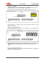
2)
Using the ‚L’ command outputs can be individually controlled.
Since most applications either use only a few outputs intensively, the first 7 (ID 0..6) are
handled specially.
VIPpanel User’s manual V1.1 12.8.2005
25/35
www.mjbc.ch
M.J.Butcher Consulting
solution engineering
User’s manual
Example 1: ‚L’ 0x55 0x0d
Sets the outputs with ID 0, 2, 4 and 6 to the logical ‘1’ state and the outputs with the IDs 1,
3 and 5 to the logical ‘0’ state. The other outputs are not modified.
The requirement for this spcial treatment if that the MSB of the value must be ‘0’.
$ %--+
& % & % & % &
,
+
*
)
(
'
&
%
0 0 %1 ** %1 . %
&
%
%2
(%
'/
'.
3
',
'+
'*
')
%
&
%
&
$ +-- $ %
,
+
*
)
(
'
&
%
$ &*
-- $ .
$ '**
-- $ '),
(&
&
$
$
$
$
$
$
$
$
%
Generally the outputs are grouped in to bytes and can be addressed in blocks, as shown in
the following examples.
Example 2: ‚L’ 0xa2 0x55 0x55 0x0d
Sets the outputs with IDs 8, 10, 12, 14, 16, 18, 20, 22 to logical ‚1’ and the outputs with IDs
9, 11, 13, 15, 17, 19, 21, 23 to logical ‚0’
0 0 %1 ' %1 ** %1 ** %1 . %
&
'
(
)
&
%
&2
%
4
'5 6 7
(%
'/
'.
',
%
%
56
'+
'*
&
%
-'
')
,
+
*
)
(
'
&
%
$ &*
-- $ .
$ '**
-- $ '),
(&
&
% & % & % & % & % & % & % & % &
'(
''
'&
'%
&/
&.
&,
&+
&*
&)
&(
&'
&&
&%
/
.
%% 2
%& 2
&% 2
&& 2
$
$
$
$
$
$
$
$
$
$
$
$
$
$
$
$
7
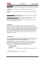
When the MSB is set, the first byte serves as an address. The next two bits define the
length of the data (from 1 to 4 bytes) and the last 5 bits in the byte define the block
address.
Example 3: ‚L’ 0xdf 0xff 0xff 0x7f 0x00
Sets the outputs with IDs 232 to ID 238 and IDs 240 to ID255 to logical ‚1’ and the outputs
with IDs 0..ID 6 and ID239 to logical ‚0’.
VIPpanel User’s manual V1.1 12.8.2005
26/35
www.mjbc.ch
M.J.Butcher Consulting
solution engineering
User’s manual
7
%% 2
%& 2
&% 2
&& 2
&
'
(
)
0 0 %1
&
&2
&
%
4
(5 6
&
&
56
&
%1 %1 %1 , %1 %% %1 . %
&
&
- (&
%
%
%
%
%2
7
%
3
%
%
%
$ +-- $ %
% % % % % % %
$
$
$
$
$
$
$
$
$
$
$
$
$
$
$
$
$
$
$
$
$
$
$
$
$
$
$
$
$
$
$
$
,
+
*
)
(
'
&
%
'**
'*)
'*(
'*'
'*&
'*%
')/
').
'),
')+
')*
'))
')(
')'
')&
')%
'(/
'(.
'(,
'(+
'(*
'()
'((
'('
& & & & & & & & & & & & & & & & % & & & & & & &
(%
'/
'.
',
'+
'*
')
,
+
*
)
(
'
&
%
$ &*
-- $ .
$ '**
-- $ '),
(&
The protocol allows the combination of multiple blocks from 1..4 bytes in length and also
the first 7 bits (IDs 0..7), in order to achieve an optimal combination of flexibility and
efficiency. This means that front panels with only a small number of LEDs / outputs are
efficient but larger designs also easily possible.
After the completion of the operation the VIPpanel sends an ACK. In case the message
format is not valid, the VIPpanel returns a NACK and the command is ignored. Unavailable
outputs are ignored but no NACK is returned in this case.
You can find a complete working example of a C-code implementation fort he control of
LEDs in the demo project.
2)
Using the ‚N’ command, the intensity of the LEDs can be controlled. After a reset this is set
to a maximul level, which means that active LEDs have maximul intensity. The VIPpanel
confirms the operation with an ACK. If the intensity control ciruit is not available in the
hardware or the format of the telegram is invalid, the VIPpanel returns a NACK.
Example 1: ‚N’ 0x7f 0x0d
Sets the intensity to 50%
Example 2: ‚N’ 0xbf 0x0d
Sets the intensity to 75%
VIPpanel User’s manual V1.1 12.8.2005
27/35
www.mjbc.ch
User’s manual
M.J.Butcher Consulting
solution engineering
Key settings and responses
Messages from the VIPpanel
Key change event 1)
‚k’ (0x68) xx
Key changes; this is automatically sent
when operating in event mode or as
response to a key status request
Key status 2)
‚K’ (0x48)
Requests the present key state (this
can be used to poll the keys)
Buzzer ON/OFF 3)
‚E’ (0x45) xx
Turns the automatic key beep on or off
Setting for auto-beep 4)
‚I’ (0x49) xx
Sets automatic beep to individual keys
(this setting requires that the key beep
is activated by using the ‘E’ command)
Commands to the VIPpanel
1)
The protocol for key change events uses the same format as that used to control LEDs.
The status of the first 7 keys with IDs 0..6 is transmitted using non addressed messages.
If there are more than 7 keys, higher IDs (greater than ID6) are transmitted using
addressed messages.
If there are more than one key change at the same time, all changes are reported in single
message. Keys are debounced by the VIPpanel with a debounce time of about 50ms,
which meansn that no two changes will be sent at a facter rate than this.
Whether the VIPpanel expects an ACK in response to a key change depends on its
operating mode. If the ACK mode of operation has been selected, key changes which do
not receive an ACK within a period of 1s will be repeated up to 7 times.
2)
The VIPpanel responds with a ‘k’ response rather than an ACK. All changes since the last
request will be reported. Should the status be requested at a too low rate (less often than
about 100ms) it is possible that very short key presses are missed. For this reason the
event mode of operation is to be preferred.
This request is especially useful immediately after the front panel has startet in order to
recognise keys which were in a pressed state on power up. A ‘k’ response with no data
means that there were no changes since the last request and an empty response after
power up signifies that no keys were held down at power up.
3)
‚E’ 0x01 0x0d
Activates key beeps
‚E’ 0x00 0x0d
Deactivates key beeps.
‚E’ 0x02 0x0d
Activates individual key beeps for individual keys which have been assigned by using the ‘I’
command. Attention: this function is only available in event mode. The front panel does not
generate key beeps in polling mode.
The VIPpanel responds with an ACK.
4)
This command has the same format as the LED control telegram.
VIPpanel User’s manual V1.1 12.8.2005
28/35
www.mjbc.ch
User’s manual
M.J.Butcher Consulting
solution engineering
When a key ID is set to a logical ‚1’ the VIPpanel generates a beep when the
corresponding key is pressed. The tone has a frequency of 3000Hz and lasts 75ms. This
setting is only valid when the ‘E’ command has set the buzzer mode accordingly.
This message is always acknowledged with an ACK as long as its format is correct,
whether there is a buzzer available or not. A NACK is returned shoud the format be
incorrect and the command wil be ignored.
Telegrams for Buzzer control
Commands to the VIPpanel
Buzzer tone 1)
1)
‚Z’ (0x5a) xx yy Generates a beep with variable
frequency and length
The buzzer may be used for acoustic signalisation.
The command ‚Z’ 0xXX 0xYY 0x0d switches the buzzer on for a period of 0xXX times
50ms and with a frequency of 0xYY times 100Hz.
A duration of 0 switches the buzzer on continuously. A frequency of 0 switches a
continuous tone off again.
This command is always acknowledged immediately with and ACK.
In case the hardware is not capable of generating the requested frequency, the buzzer will
be activated with the next best possible frequency. If the hardware doesn’t support a
buzzer the command is ignored.
The automatic key beep is deactivated when a tone is being generated by the buzzer.
If a second such command is received before the first duration has completed, the second
command takes over from the previous command.
VIPpanel User’s manual V1.1 12.8.2005
29/35
www.mjbc.ch
User’s manual
M.J.Butcher Consulting
solution engineering
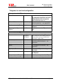
Overview of telegrams
‘A’
Accept
‘B’
Backlight
‘C’
Contrast
‚D’
Display control
‘E’
key bEep On/Off
‚F’
Force Connection
‚G’
Get LCD Memory [‘A’ Address / ‘R’ RAM]
‚H’
Hi (Network contact)
‘I’
Individual key beep
‘K’
Key status request
‘L’
set LEDs (or outputs)
‚M’
Mode
‚N’
LED iNtensity
‘O’
Output pattern
‘P’
set Pattern to LCD
‚R’
Reset
‚S’
Set Position and write display [>= V1.1]
‚T’
Type request
‚V’
Software Version request
‚W’
Write display
‘Z’
buZZer control
VIPpanel User’s manual V1.1 12.8.2005
30/35
www.mjbc.ch
User’s manual
M.J.Butcher Consulting
solution engineering
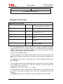
9) Appendix B: Communication over Ethernet / TCP/IP
The communication over Ethernet differs from that of a serial connection in several respects:
• The connection can either be very fast (for example over an Intranet) or very slow
(example over the Internet).
• Some data loss is probably; collisions, transmission errors, router errors, etc. Such a
connection is simply less reliable than a direct serial connection.
• It is possible that there are more than one connection attempts from different
sources..
• The location and IP addresses of the communication partners can change.
Due to these differences, there are several aspects which must be considered in order to
ensure reliable communication.
Reset
After the reset of an Internet enabled front panel the Reset ‘r’ message is sent to a single
fixed location. This is generally not a problem in an Intranet since the Partner IP address can
be configured and the link is equivalent to a fixed point-to-point connection.
It is a different situation if the Partner has not been configured or its IP address is not knows
(for example when the Partner received a temporary IP address from a service provider or
DHCP server). In this case the Reset message can not be delivered and a missing partner
needs to be identified by another means.
Establishing contact
If the Partner IP address has been configured and the front panel sends the Reset ‘r’
message to this partner address a link will be immediately established analogue to a serial
connection.
Should this not be the case, a connection can be actively established by using the ‘H’
command. The front panel answers with its present operating mode as well as the present
connection status.
The answer ‚h’ 0x01 0x00 0x0d shows, for example, the mode 0x01 and the connection
status 0x00.
The connection states are:
0x00 – No existing connection (a normal connection will be immediately established)
0xX1 – A normal connection exists (this connection will not be interrupted)
0xX2 – Supervisor connection exists (this connection will not be interrupted)
0xXf – Unknown connections are not allowed
Should the connection already exist with the requesting communication partner then the bit
0x10 will be set in the status message (for example 0x11 means that a normal connection
already exists with the requesting communication partner)
It is to be noted that the Ethernet operation always uses a CRC-16 and counter mode of
operation.
No existig connection: The connection link will be immediately set to the requesting IP
address. The status changes to normal connection.
VIPpanel User’s manual V1.1 12.8.2005
31/35
www.mjbc.ch
User’s manual
M.J.Butcher Consulting
solution engineering
Normal connection: The existing connection is not disturbed but the requester may demand
the link by using the ‘F’ (force connection) command or else later see whether the connection
becomes free.
‚F’ 0x00 0x0d – Set link to normal connection. Other requestors can then force a new
connection..
‚F’ 0x01 0x0d – Set link to Supervisor connection. Other requestors can then not take over
the link.
Supervisor connection: The existing link will not be distrurbed. The connection can not be
taken over but may become free in the future.
Unknown connections not allowed: Only the configured Partner IP address is allowed to
communicate with the front panel. The connection will never become free.
An invalid attempt to take over a connection will receive a NACK whereas a successful
attempt will be acknowledged with an ACK.
Keep alive
When a link is connected in the Supervisor state it is blocks all other user attempts to
connect. This state exists until either the supervisor releases the connection, setting its
connection state to a normal connection, or until the Supervisor connection times out (default
5 minutes) and sets itself automatically to a normal connection. Should the Supervisor user
require that the Supervisor connection exist for a longer period of time it can request the
Supervisor connection again before it has timed out, which restarts the time out period.
If the Supervisor wants to immediately give up the Supervisor connection it can do so by
setting a normal connection.
UDP Protocol
UDP (User Datagram Protocol) is an efficient TCP/IP protocol which is connectionless (TCP
is for exampe connection oriented). The protocol is however not reliable since it doesn’t
include data integrity checking and doesn’t use handshaking.
The VIPpanel always uses active message counters and CRC-16 when operating in
Ethernet mode in order to ensure a robust and secure connection. This mode must be
respected since the VIPpanel doesn’t accept operation without these parameters.
A UDP frame carrying the VIPpanel protocol has the following construct:
ETHERNET HEADER
INTERNET PROTOCOL
UDP HEADER
DATA
[VIPpanel telegram including message counter and CRC-16 ]
The VIPpanel protocol packet still uses escape sequencing.
VIPpanel User’s manual V1.1 12.8.2005
32/35
www.mjbc.ch
User’s manual
M.J.Butcher Consulting
solution engineering
Ethernet / Internet with VIPpanel and the Demo-Application
The demo application uses a simulated serial connection between the VIPpanel and the
application.
When you establish a LAN connection from the demo application to a VIPpanel conform
front panel, the application is informed and automatically switches to the correct protocol
operating mode so that the LAN mode works. The protocol operates now with message
counter and CRC-16 to ensure compatibility and a secure connection.
The VIPpanel performs a parallel operation and transfers protocol messages between the
Ethernet connector and the internal simulated serial port. Your own designs based on serial
port operation can thus also be simply tested in LAN mode if desired.
10/100M LAN operation
An Internet enabled front panel can often be set for 10M or 100M LAN operation as well as
auto-negotiation. It should be noted when throughput is not an issue, the 10M mode setting
may be a good choice since it requires less power consumption than the 100M mode
[reference 400mW in 10M mode and 0,8W in 100M mode].
Nowadays switches are extensively used in Ethernet LANs and these adapt to the devices
speed setting. This is not the case when hubs are used to interface the device to a network;
in this case the devices speed must be set to that of the hub’s speed, otherwise the
connection will not work.
VIPpanel User’s manual V1.1 12.8.2005
33/35
www.mjbc.ch
User’s manual
M.J.Butcher Consulting
solution engineering
10) Appendix C Tips for the control of LCDs
User definable characters
Character displays support up to 8 user definable characters. These are situated in the font
table from address 0x00 and there are 16 spaces for these characters since they be either
5x8 or 5x11 in size.
In order to program the characters, the appropriate address must be set in CGRAM. The
command ‘D’ 0x400 0x0d for example sets the address 0x00 in CGRAM [CGRAM Command
0x40 + Address 0]. Afterwards 64 data bytes can be written, whereby only the 5 LSB are
valid.
In 5x8 Mode 8 characters with each 8 rows by 5 pixels can be defined. The row address is
incremented after each byte written. After the write to the last line of character 0x07 the
address counter overflow back to 0x00.
The characters 0x00 and 0x08, 0x01 and 0x09….0x07 and 0x0f are interpreted as equal to
the character in the range 0x00..0x07.
Example:
‚D’ 0x40 0x0d [sets the CGRAM address to 0x00]
‚W’ 0x1f 0x11 0x11 0x11 0x11 0x11 0x11 0x11 0x0d [defines the 5x8 character
address has been incremented to 0x08.
]. The
‚D’ 0x78 0x0d [sets the CGRAM address to 0x38 (character 0x07)]
‚W’ 0x1f 0x1f 0x1f 0x1f 0x00 0x00 0x00 0x00 0x0d [defines the 5x8 character ]. The
address has been incremented back to 0x00 (overflow).
‚W’ 0x00 0x00 0x00 0x00 0x1f 0x1f 0x1f 0x1f 0x0d [defines the 5x8 character ]. The
address has been incremented to 0x08 AND the character 0x00 has been
overwritten.
In 5x11 Mode 4 characters with each 11 rows by 5 pixels can be defined. This mode is only
possible in the LCD single line mode and requires an LCD with at least 2 lines. The last 3
lines of the character are displayed on the lower LCD line and the lower 5 character lines on
this LCD line are blank.
The row address is incremented after each byte written.
In order to define the a following character it is necessary to either command the start
address of the character or else write dummy values into the last 5 line of a previous
character, which increments the address to the start of the next one.
In this mode the characters 0x00 and 0x01, 0x02 and 0x03….0x06 and 0x07 are represented
by the characters 0x00, 0x02, 0x04 and 0x06.
As in the 5 x 8 Mode the address counter overflows after the character 0x07 and the
characters 0x08, 0x09…0x0f are equivalent to the characters 0x00.. 0x07.
Example:
‚D’ 0x40 0x0d [sets the CGRAM address 0x00 – characters 0x00 and 0x01]
VIPpanel User’s manual V1.1 12.8.2005
34/35
www.mjbc.ch
User’s manual
M.J.Butcher Consulting
solution engineering
‚W’ 0x1f 0x11 0x11 0x11 0x11 0x11 0x11 0x11 0x11 0x11 0x11 0x0d [defines the
5x11character ]. The address has bee incremented to 0x0b.
‚D’ 0x50 0x0d [sets the CGRAM address to 0x10 (characters 0x02 and 0x03)]
‚W’ 0x1f 0x1f 0x1f 0x1f 0x00 0x00 0x00 0x00 0x00 0x00 0x00 0x0d [defines the 5x11
character ].
Note:It is not recommended to switch between 5x8 and 5x11 modes during normal operation.
Different LCD types tend to react diffently and often unpredicatably when this is attempted.
Shift mode
The LCD simulator in the VIPpanel attempts to reproduce the exact behaviour of a real LCD.
When text is written to the LCD display in shift mode it is often observed that different LCD
types can behave slightly differently. Some LCDs types also show unpredictable behaviour.
Due to these experiences and the complex behavious when a shift write is performed at a
line change this mode needs to be carefully used and is often not recommended. It is
suggested that the VIPpanel control be first tested (it corresponds to normal LCD operation)
and the shift operation possibly be implemented in the control software.
VIPpanel User’s manual V1.1 12.8.2005
35/35
www.mjbc.ch