1
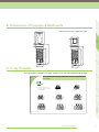
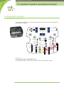
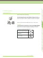
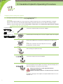
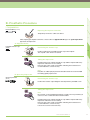
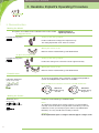
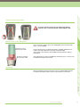
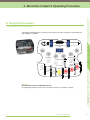
USER GUIDE
INNOVATING METAL-FREE IMPLANTOLOGY
AXIS Implant System - User Guide
2
Index
1. Implant System
1
2. Pre-operative Planning
2
A. Indications & Contra-indications
2
B. Dimensions of Implants & Abutments
3
C. X-ray Template
3
3. Hexalobe Implant’s Operating Procedure
4
A. Surgical Procedure
4
i. Instruments Presentation
4
ii. Implant Site Preparation
6
iii. Implant Insertion
7
iv. Soft Tissue Management
10
v. Healing
10
B. Prosthetic Procedure
11
i. Impression
11
ii. Reconstruction
12
iii. Rehabilitation
14
4. Monobloc Implant’s Operating Procedure
15
A. Surgical Procedure
15
i. Instruments Presentation
15
ii. Implant Site Preparation
17
iii. Implant Insertion
18
iv. Healing
21
B. Prosthetic Procedure
21
i. Impression
21
ii. Reconstruction
21
iii. Rehabilitation
22
5. Implantation Follow-up
23
6. Cleaning - Sterilizing - Storage
24
7. Technical Support
25
Appendix 1: Rotation Speeds and Torques
26
Appendix 2: Labeling Explanations
27
www.axis-biodental.ch
3
AXIS Implant System - User Guide
4
1. Implant System
1
AXIS provides a non-metallic dental implant system. AXIS implants are available in two different
versions: a screwed two-piece and a one-piece implant.
AXIS Hexalobe Implants
ref. A1079
ref. D1154
ref. A1080
ref. D1155
ref. D1157
3
8
10
12
ref. A1078
2
This two-piece implant is composed of an HIP Y-TZP zirconia fixture, a high performance polymer
abutment and a prosthetic or holistic-gold screw.
Straight
15° angled
15° angled
abutment
abutment A
abutment B
Hexalobe M8 Hexalobe M10 Hexalobe M12
Prosthetic screw Holistic screw
ref. D1149
ref. D1047
4
AXIS Monobloc Implants
This one-piece implant is made out of HIP Y-TZP zirconia.
Monobloc M8 Monobloc M10 Monobloc M12
5
ref. A1076
6-7
Appendix
ref. A1075
8
10
12
ref. A1074
www.axis-biodental.ch
1
AXIS Implant System - User Guide
2. Pre-operative Planning
A. Indications & Contra-indications
Indications
Note
The rule for choosing a dental implant is to use the one with the greatest diameter, with the
resistance of that implant being proportional to the cube of its diameter.
AXIS implants are especially indicated to replace a single tooth (1 tooth - 1 implant).
Contra-indications
General Contra-indications
Contra-indication include, but are not limited to cardiovascular disease, uncontrolled diabetes,
coagulation disorders (including taking anticoagulants), metabolic bone disease, chemotherapy or
radiation treatment, chronic inflammation, metabolic or systemic disorders associated with lesions
and/or bone healing, the use of pharmaceutical products that block or modify bone healing.
Absolute Contra-indications
Contra-indication include, but are not limited to uncontrolled para-functional diseases (bruxism,
clenching or grinding of teeth), insufficient bone length or width, insufficient inter-arc gap, intraoral
infection, insufficient coverage of the soft tissue and disorders that impede the ability of patients
to maintain adequate oral hygiene.
We may add other factors that can negatively influence success rates, such as smoking.
2
1
B. Dimensions of Implants & Abutments
Note: Dimensions are in millimeters (mm).
3
2
4
C. X-ray Template
An X-ray template is available (ref. I1098). It allows you to select the adequate implant length.
X-Ray Template
Ø4.0
0
2
4
6
8
10
12
0
2
4
6
8
10
12
110 %
100 %
0
2
4
6
8
10
12
0
2
4
6
8
10
12
0
2
4
6
8
10
12
140 %
130 %
120 %
0
2
4
6
8
10
12
0
2
4
6
8
10
12
0
2
4
6
8
10
12
150 %
Ø4.0
Ø4.0
Ø4.0
6-7
Ø4.0
Ø4.0
Ø4.0
160 %
Appendix
Note: This X-Ray template can be used
for one-piece implants as well as for
two-piece implants.
5
Ø4.0
170 %
I1098 - EN / 11-2011
© Axis biodental SA : All rights er served
www.axis-biodental.ch
3
AXIS Implant System - User Guide
3. Hexalobe Implant’s Operating Procedure
A. Surgical Procedure
i. Instruments Presentation
A sterilizable implantology kit (ref. B1085), containing all necessary instruments required to place
AXIS implants is available.
Torque wrench
C1031
Wrench adapter
C1030
Extension
Screwdriver
Implant Holder
Round bur
C1029
C1156
B1021/B1108
Pilot drill
Gauge
B1011
Drill S
Drill M
B1082
B1013
B1024
B1022
B1014
B1015
Attention
All instruments must be sterilized before use.
For sterilizing procedures, please refer to Section 6: Cleaning - Sterilizing - Storage.
4
Tap M
Depth
gauge M
1
In addition to the content of the surgical kit, other instruments are available.
Tissue punch (ref. B1010)
Profile Drill (ref. B1170)
Point drill (ref. B1012)
2
Handpiece extension (ref. C1029)
3
Three tick marks indicating the working depth (8, 10 and 12 mm) have been etched on the
instruments required for realizing the implant site.
4
12 mm
10 mm
8 mm
Drill M
0,8 mm
Pilot drill
Gauge
Drill S
Drill M
Depth
gauge
Tap
5
Working depth
Important
Appendix
6-7
In order to create optimal conditions for the integration of the implant, it is imperative to respect
the recommended speeds and to apply a reasonable pressure during the site preparation.
The respect of these rules will prevent over-heating which could slow or prevent the
osseointegration of the implant due to bone necrosis.
www.axis-biodental.ch
5
AXIS Implant System - User Guide
3. Hexalobe Implant’s Operating Procedure
ii. Implant Site Preparation
Osseous Crest Access
Tissue punch (B1010)
For accessing the bone, it is possible to use a scalpel or the tissue punch
proposed by AXIS.
A large round bur can be used to prepare the bone crest.
Implant Site Preparation
Round bur (B1011)
Point drill (B1012)
Mark the implant site using a round bur.
The point drill can also be used at this stage.
1.4 mm round bur and point drill: max. 800 rpm
Ø 2.4 mm Primary Drilling
Pilot drill (B1013)
Drill the implant site to the final depth using the pilot drill.
Pilot drill: max 800 rpm
Parallelism Control
Direction indicator (B1022)
Measure the depth of the site and assess its orientation using the direction
indicator.
Ø 2.9 mm Drilling
Drill S (B1014)
Widen the implant site using the S drill (yellow ring).
Drill S: max 550 rpm
Ø 3.4 mm Drilling
Drill M (B1015)
Widen the implant site using the M drill (red ring).
Drill M: max 500 rpm
Depth Control
Depth gauge M
(B1024)
Measure the depth of the site using the M depth gauge (red ring).
Ø 4.0 mm Tapping
Tap M (B1082)
For class I and II bone, tap the site using the tap M (red ring).
Tap M: max 15 rpm and 35 Ncm
Ø 4.5 mm Profile Drilling
Profile drill (B1170)
6
If desired, the implant can be inserted deeper into the bone using the profile
drill.
Working depth indicated on the instrumentation are specific for
transgingival implant positioning. When using the profile drill,
the implant site should be 1.5 mm deeper.
1
iii. Implant Insertion
Implant Unpacking
Remove the blister from its packaging.
2
Each AXIS implant has its own article and batch number. To ensure the
necessary tracking of products, this information must appear on the patient
folder. For this purpose, labels are available on the blister of each implant.
Remove the lid of the blister and deposit the inlay on a sterile surface.
3
Precautions
The implant should not be placed in the mouth if the packaging is damaged
or if the implant was in contact with a non-sterile surface. In this situation,
the product must be replaced. Implant resterilizing is not allowed.
4
Packaging and sterilizing images (Appendix 2)
Do not use if packing is damaged
Do not reuse
Appendix
6-7
5
Do not resterilize
www.axis-biodental.ch
7
AXIS Implant System - User Guide
3. Hexalobe Implant’s Operating Procedure
Gripping and Inserting the Implant
Two types of protocols are available: - using the torque wrench (A),
- using a right angle (B).
Important
Our Hexalobe implant holder has a mechanical fuse feature that prevents any over-torque application or irregular
efforts. In case of misuse, the Hexalobe implant holder may break at the fuse level. In order to complete surgery
despite an implant holder rupture, it is recommended to always have a second Hexalobe implant holder available.
A. Protocol with the Torque Wrench
Hexalobe implant
holder (B1021)
Connect the implant holder to the wrench adapter.
Wrench adapter (C1030)
Torque wrench (C1031)
Hold the blister horizontally and connect the implant holder to the implant.
Release the implant from its location by rotating it over its apical end.
Note
A cavity was created on the inlay to deposit, if necessary,
the implant on a sterile surface.
Start inserting the implant manually.
Connect the torque wrench to the adapter.
Screw the implant into the implant site until the end of the thread (see the
opposite paragraph concerning Insertion Depth).
Always keep the best possible alignment between
instruments and implant.
Implants should be screwed to a maximum torque of 35 Ncm.
Note
To avoid any damage to the implant, the implant holder breaks in case of
improper use.
8
1
B. Protocol with the right angle
Hexalobe implant
holder (B1021)
Connect the implant holder to the right angle.
If necessary, use an handpiece extension.
Handpiece extension
Hold the blister horizontally and connect the implant holder to the implant.
2
(C1029)
Release the implant from its location by rotating it over its apical end.
3
Note
A cavity was created on the inlay to deposit, if necessary,
the implant on a sterile surface.
Screw the implant into the implant site until the end of the thread (see
paragraph concerning Insertion Depth below).
Note
To avoid any damage to the implant, the implant holder breaks in case of
improper use.
5
AXIS implants are transgingival. The implant’s neck should be approximately 1.5 mm above the bone
crest.
6-7
1.5
They can also be inserted deeper into the bone using the profile drill.
Appendix
Insertion Depth
4
Always keep the best possible alignment between
instruments and implant.
Implants should be screwed to a maximum torque of 35 Ncm
and a maximum speed of 15 rpm.
Working depth indicated on the instrumentation are specific for
transgingival implant positioning. When using the profile drill,
the implant site should be 1.5 mm deeper.
www.axis-biodental.ch
9
AXIS Implant System - User Guide
3. Hexalobe Implant’s Operating Procedure
iv. Soft Tissue Management
Several soft tissue management options are proposed: - Cover screw (A),
- Cover screw (B),
- Temporary abutment (C).
A. Cover screw
A cover screw is provided with each AXIS Hexalobe implant. It is located
in the cavity of the blister sealed with a transparent lid.
RA Screwdriver (C1156)
Cover screw (D1145)
Remove the lid and take the cover screw with the screwdriver. Suture the
gingiva over the cover screw.
In order to avoid failures, the cover screw must be tightened
to a maximum torque of 15 Ncm.
Cover screws are partially made out of PEEK which should
not be used more than 180 days in the mouth.
B. Healing abutment
Depending of the case, gingiva formers are available in 2.5 mm or 4 mm
height.
RA Screwdriver (C1158)
Healing abutments
Use the screwdriver to tight the screw. Suture the gingiva around the
implant collar
(D1050, D1132)
Prosthetic screw
In order to avoid failures, the screw must be tightened to a
maximum torque of 15 Ncm.
Gingiva formers are made out of PEEK which should not be
used more than 180 days in the mouth.
(D1149)
C. Temporary abutment
RA Screwdriver (C1158)
Prosthetic screw
A temporary abutment is available. It allows a temporary restoration in
aesthetic zone.
(D1149)
Temporary abutment
(D1131)
Use the screwdriver to tight the screw. Realize directly a temporary crown
on the temporary abutment accordingly to the case and the standard
method of the clinic.
In order to avoid failures, the screw must be tightened to a
maximum torque of 15 Ncm.
Temporary abutments are made of PEEK which should not
be used more than 180 days in the mouth.
v. Healing
The duration of soft tissue healing and osseointegration of AXIS’ implants vary generally from 2 to 4
months. It depends on the general state of health of the patient and the quality of the bone around the
implant.
It is possible to use standard means to control the osseointegration.
10
1
B. Prosthetic Procedure
i. Impression
RA Screwdriver (C1158)
Exposing the implant connexion
2
Temporarily remove the soft tissue device.
After exposing the implant connexion, choose either a clipped transfer (A) or an open tray transfer
(B) to take an impression.
A. Clipped transfer
Hexalobe transfer cap
clic
Position and lock the hexalobe transfer cap on the implant.
The cap will «click» when it is locked.
3
Positioning the transfer cap
(D1040)
Put light impression material around the cap and the implant and heavy
impression material in the closed tray.
Place the tray in the mouth, let it harden following the manufacturer’s
recommendations, remove the tray.
4
Taking the impression
Note
Polyether or rubber polyvinylsiloxane based material are recommended
for making quality impressions.
5
B. Open tray impression
Positioning the transfer cap
Position the transfer cap and tight it manually with the provided screw.
6-7
(D1152)
Taking the impression
Note
Be sure that a corresponding perforation is made in the tray and that you
can access the screw before the material hardens.
Put light impression material around the cap and the implant and heavy
impression material in the closed tray.
Place the tray in the mouth, let it harden following the manufacturer’s
recommendations, remove the tray.
Loosen the screw to remove the tray.
www.axis-biodental.ch
Appendix
Open tray transfer
11
AXIS Implant System - User Guide
3. Hexalobe Implant’s Operating Procedure
ii. Reconstruction
Making the Model
Two options are available for the realization of the master-model: - Clipped transfer (A),
- Open tray transfer (B).
A. Clipped transfer
Setting up the analog implant
Hexalobe analog (D1042)
clic
Position and lock the analog in the impression tray.
The analog implant will «click» when it is locked.
Making the master model
Make the master model following a standard method.
B. Open tray impression
Hexalobe analog (D1042)
Setting up the analog implant
Position the analog in the connexion transfer. Tight it manually.
Making the master model
Make the master model following a standard method.
Plannification
Laboratory abutments
To choose the angulation of the restoration, straight and angulated 15°
(version A and B) laboratory abutments are available.
(D1158, D1159, D1160)
Laboratory screw
Note on difference between versions A and B abutments
(D1084)
Version A
Angulation facing
the lobe
Version B
Angulation facing
the groove
Making the Crown
Abutments (D1154,
Realize the crown following a standard method.
D1155, D1157)
Laboratory screwdriver
(C1028)
Notes
To maintain the integrity of the master model, it is recommended to
manually screw the elements using the AXIS screwdriver (ref. C1028).
Laboratory screws (ref. D1084) are green and are only dedicated for
laboratory use. They should not be used by a clinician.
Attention
Each implant must replace a single tooth and support a single crown.
12
1
Implant-Crown Assembly
2
To ensure a perfect sealing and an optimal mechanical
resistance, the crown must stands on the implant collar.
If it is necessary, only the green area, highlighted on the left-hand side
figure, can be modified.
Modification forbidden
Minimal height: 3 mm
Please note that only one abutment height is available. Abutments are
made out of High performance polymer easily adjustable.
Such changes are under the responsibility of the practitioner and the
prosthetist.
If the abutment has not been modified, a positioning key is not necessary,
the abutment being multi-symetric.
5
Scanning
4
Modification allowed
Maximal height: 5 mm
3
Modification of the Abutment
Appendix
6-7
Most of standard scanning techniques can be used with AXIS implants.
For further information, please refer to manufacturer’s instructions.
www.axis-biodental.ch
13
AXIS Implant System - User Guide
3. Hexalobe Implant’s Operating Procedure
iii. Rehabilitation
Final Abutment Set Up
Prosthetic screw
(D1149)
RA Screwdriver (C1158)
Disinfection
Before rehabilitation, neutral disinfectants (no chlorine, ammonia, or
aldehyde) should be used according to manufacturers’ recommendations
for disinfecting prosthetic parts.
Unscrew the soft tissue management device.
Place the abutment on the implant and lock it with a new screw.
Important
For rehabilitation, only use a new screw.
Laboratories screw are green and are not suitable for implantation.
In order to avoid failures, prosthetic screw must be tightened
at a maximum torque of 25 Ncm. Holistic screw must be
tightened at a maximum torque of 15 Ncm.
Crown Sealing
Comments
Before sealing the prosthetic part, it is necessary to seal the screw’s well
with a material like Teflon, gutta-percha or cotton. Do not use resin.
Seal the previously disinfected crown on the abutment. Ideally, use a
MDP resin-type adhesive. Please refer to the instructions provided by the
manufacturer.
14
4. Monobloc Implant’s Operating Procedure
1
A. Surgical Procedure
i. Instruments Presentation
2
A sterilizable implantology kit (ref. B1085), containing all necessary instruments required to place
AXIS implants is available.
Torque wrench
3
C1031
Wrench adapter
C1030
Extension
Screwdriver
Round bur
C1029
C1156
Gauge
B1011
Drill S
Tap M
Depth
gauge M
B1021/B1108
Pilot drill
4
Implant Holder
Drill M
B1082
B1013
B1024
B1014
B1015
5
B1022
Appendix
All instruments must be sterilized before use.
For sterilizing procedures, please refer to Section 6: Cleaning - Sterilizing - Storage.
6-7
Attention
www.axis-biodental.ch
15
AXIS Implant System - User Guide
4. Monobloc Implant’s Operating Procedure
In addition to the content of the surgical kit, other instruments are available.
Tissue punch (ref. B1010)
Rofile drill (ref. B1170)
Point drill (ref. B1012)
Handpiece extension (ref. C1029)
Three tick marks indicating the working depth (8, 10 and 12 mm) have been etched on the
instruments required for realizing the implant site.
12 mm
10 mm
8 mm
0,8 mm
Drill M
Pilot drill
Gauge
Drill S
Drill M
Depth
gauge
Tap
Working depth
Important
In order to create optimal conditions for the integration of the implant, it is imperative to respect
the recommended speeds and to apply a reasonable pressure during the site preparation.
The respect of these rules will prevent over-heating which could slow or prevent the
osseointegration of the implant due to bone necrosis.
16
1
ii. Implant Site Preparation
Osseous Crest Access
Tissue punch (B1010)
For accessing the bone, it is possible to use a scalpel or the tissue punch
proposed by AXIS.
2
A large round bur can be used to prepare the bone crest.
Implant Site Preparation
Round bur (B1011)
Point drill (B1012)
Mark the implant site using a round bur.
The point drill can also be used at this stage.
1.4 mm round bur and point drill: max. 800 rpm
3
Ø 2.4 mm Primary Drilling
Pilot drill (B1013)
Drill the implant site to the final depth using the pilot drill.
Pilot drill: max 800 rpm
Direction indicator (B1022)
Measure the depth of the site and assess its orientation using the direction
indicator.
4
Parallelism Control
Ø 2.9 mm Drilling
Drill S (B1014)
Widen the implant site using the S drill (yellow ring).
Drill S: max 550 rpm
Drill M (B1015)
5
Ø 3.4 mm Drilling
Widen the implant site using the M drill (red ring).
Drill M: max 500 rpm
Depth gauge M
(B1024)
Measure the depth of the site using the M depth gauge (red ring).
6-7
Depth Control
Tap M (B1082)
For class I and II bone, tap the site using the tap M (red ring).
Tap M: max 15 rpm and 35 Ncm
Ø 4.5 mm Profile Drilling
Profile drill (B1170)
Appendix
Ø 4.0 mm Tapping
If desired, the implant can be inserted deeper into the bone using the profile
drill.
Working depth indicated on the instrumentation are specific for
transgingival implant positioning. When using the profile drill,
the implant site should be 1.5 mm deeper.
www.axis-biodental.ch
17
AXIS Implant System - User Guide
4. Monobloc Implant’s Operating Procedure
iii. Implant Insertion
Implant Unpacking
Remove the blister from its packaging.
Each AXIS implant has its own article and batch number. To ensure the
necessary tracking of products, this information must appear on the patient
folder. For this purpose, labels are available on the blister of each implant.
Remove the lid of the blister and deposit the inlay on a sterile surface.
Precautions
The implant should not be placed in the mouth if the packaging is damaged
or if the implant was in contact with a non-sterile surface. n this situation,
the product must be replaced. Implant resterilizing is not allowed.
Packaging and sterilizing images (Appendix 2)
Do not use if the packaging is damaged
Do not reuse
Do not resterilize
18
Gripping and Inserting the Implant
1
Two types of protocols are available: - using the torque wrench (A),
- using a right angle (B).
A. Protocol with the Torque Wrench
Connect the implant holder to the wrench adapter.
2
Monobloc
implant-holder (B1108)
Wrench adapter (C1030)
Hold the blister horizontally and connect the implant holder to the implant.
Torque wrench (C1031)
Note
A cavity was created on the inlay to deposit, if necessary,
the implant on a sterile surface.
3
Release the implant from its location by rotating it over its apical end.
4
Start inserting the implant manually.
5
Connect the torque wrench to the adapter.
Always keep the best possible alignement between
instruments and implants.
Implants should be screwed to a maximum torque of 35 Ncm.
6-7
Screw the implant into the implant site until the end of the thread (see the
opposite paragraph concerning Insertion Depth).
Appendix
Remove the instruments and suture the gum.
www.axis-biodental.ch
19
AXIS Implant System - User Guide
4. Monobloc Implant’s Operating Procedure
B. Protocol with the right angle
Monobloc
implant-holder (B1108)
Connect the implant holder to the right angle.
If necessary, use an handpiece extension.
Handpiece extension
(C1029)
Hold the blister horizontally and connect the implant holder to the implant.
Release the implant from its location by rotating it over its apical end.
Note
A cavity was created on the inlay to deposit, if necessary,
the implant with the implant holder on a sterile surface.
Screw the implant into the implant site until the end of the thread (see
paragraph concerning Insertion Depth below).
Always keep the best possible alignment between
instruments and implants
Implants should be screwed to a maximum torque of 35 Ncm
and a maximum speed of 15 rpm.
Remove the instruments and suture the gum.
Insertion Depth
Monobloc AXIS implants are transgingival. The implant’s neck should be approximately 1.5 mm above
the bone crest.
1.5
They can also be inserted deeper into the bone using the profile drill.
Working depth indicated on the instrumentation are specific for
transgingival implant positioning. When using the profile drill,
the implant site should be 1.5 mm deeper.
20
To avoid loading the implant during osseointegration, AXIS biodental recommends achieving
temporary rehabilitation in under-occlusion mode.
1
iv. Healing
It is possible to use standard means for the control of osseointegration.
2
The duration of soft tissue healing and osseointegration of AXIS’ implants vary generally from 2 to 4
months. It depends on the general state of health of the patient and the quality of the bone around the
implant.
B. Prosthetic Procedure
i. Impression
clic
Positioning the transfer cap
3
Monobloc transfer cap
(D1036)
Position and lock the transfer cap on the implant.
The cap will «click» when it is locked.
Put light impression material around the cap and the implant and heavy
impression material in the closed tray.
4
Taking the impression
Place the tray in the mouth, let it harden following the manufacturer’s
recommendations, then remove the tray.
5
Note
Polyether or rubber polyvinylsiloxane based material are recommended
for making quality impressions.
ii. Reconstruction
Setting up the analog implant
Monobloc analog
Position and lock the analog implant in the impression tray.
The analog implant will «click» when it is locked.
Making the master model
Make the master model following a standard method.
www.axis-biodental.ch
Appendix
clic
6-7
(D1037)
21
AXIS Implant System - User Guide
4. Monobloc Implant’s Operating Procedure
Making the Crown
Make the crown following a standard method.
It is recommended to sandblast the abutment in order to increase the
adhesion of the crown.
Attention
Each implant must replace a single teeth and support a single crown.
Implant-Crown Assembly
For mechanical reasons and to ensure the sealing, the crown
must stands on the implant chamfer.
Modification of the Abutment
Modification allowed
Maximal height: 2,5 mm
Modification forbidden
Minimal height: 2,5 mm
AXIS recommends not modifying the abutment. However, if it is
necessary, only the green area, highlighted on the left-hand side figure,
can be modified.
The modification of the abutment must be made with a fine diamond bur
under irrigation and with moderate pressure in order to avoid heating the
material and generating micro-cracks.
Such changes are the responsibility of the practitioner and the prosthetist.
Scanning
Most of standard scanning techniques can be used with AXIS implants.
For further information, please refer to manufacturer’s instructions.
iii. Rehabilitation
Crown Sealing
Comments
Neutral disinfectants (no chlorine, ammonia, or aldehyde) should be used
according to manufacturers’ recommendations for disinfecting prosthetic
parts.
Seal the previously disinfected crown on the abutment. Many adhesives
for the bonding of zirconium oxide are available on the market. Ideally,
sandblast the abutment and use a MDP resin-type adhesive. Please refer
to the instructions provided by the manufacturer.
22
5. Implantation Follow-up
1
To prevent any problems, regular clinical follow-up is recommended. Ideally, the tracking should be
realized by the clinician in charge of the implantation.
After implantation: Inform the patient on the post-operative procedure in case of any problem.
Draw the patient’s attention to the importance of a good dental hygiene and its influence on the
implantation success.
2
The follow-up, proposed here-under, must be adapted accordingly to the clinical history of each
patient.
After rehabilitation: 6 months after rehabilitation, a follow-up visit will ensure the perfect behavior
of the implant. Inform the patient about the importance of communicating all problems encountered
(discomfort, ache...).
Long term: It is recommended to realize an annual X-ray. More controls could be necessary for
A good follow-up, ensured by a dentist and/or a dental hygienist, as well as a good dental hygiene,
are necessary conditions for the long-term success of an implantation.
3
high risk patient, suffering from parodontitis for example.
Appendix
6-7
5
4
As for natural teeth, implants are exposed to influences of the buccal cavity: dental plaque, tartar,
bacteria... In case of insufficient care, complications (inflammation, bleeding...) can lead to the loss
of the implant.
www.axis-biodental.ch
23
AXIS Implant System - User Guide
6. Cleaning - Sterilizing - Storage
All devices entering into direct contact with the patient should be sterilized prior to use
Exceptions:
- Products clearly identified as sterile (implant with the cover screw).
- Abutments and crowns must be decontaminated prior to use with a low or intermediate EPAregistered hospital disinfectant. Strictly follow manufacturer’s instructions.
Non-sterile components should be removed from their original packaging prior to sterilizing.
Cleaning and sterilizing of these components before their first use is under the responsibility of the
clinician.
Sterilizing Steps
Decontamination: Put the instruments in a disinfectant solution immediately after use. Do not let
the contaminated instruments dry.
Cleaning and disinfection: Disassemble the instruments that can be taken apart (torque wrench).
Group components according to their composing materials in order to avoid electrolysis and
corrosion.
Submerse them in a disinfectant:
- Cleaning solutions with high chlorine content or oxalic acid are inappropriate for the cleaning of
stainless steel instruments (risk of corrosion)
- Alkaline products with a pH higher than 9 are inappropriate for cleaning tools made of anodized
aluminum (risk of deteriorating the surface).
Cleaning can be done manually or mechanically (by ultrasound).
Be careful to dry the parts with clean compressed air.
Inspection: Check for cleanliness and proper function of instruments and components.
Reassemble the disassembled instruments. Replace damaged instruments.
To ensure optimal performance, the rotating equipment should not be used more than 10 times.
Packaging: The instruments can be packaged individually or inserted in their dedicated location in
the implantology kit, which will be then packed before sterilizing.
Sterilizing: Chemical and hot air sterilizing are inappropriate. Sterilizing by saturated steam is
recommended using the following parameters: 134 °C during 18 minutes. The recommended drying
time should be between 20 to 60 minutes.
For components sterilized at dental practice, the validity depends on various factors such as material
used for packing, storage conditions... refer to standard procedure of the dental practice.
For sterile delivered components, an expiration date is indicated on the labelling (see Appendix 2).
No component must be used beyond the expiration date.
Storage: Store the bags in a clean and dry place.
24
7. Technical Support
1
What is to be done in case of problem or if you have any question?
In case of problems or if you have any questions, please contact your local representative (agent,
distributor, ...).
Note: Before anything else, be sure to clean the implant connection and remove any fragments.
Point driver (1A)
Realization of a drilling point
Insert the point driver (1A) into the implant connection and insert the
pointer (1B) with no speed until it is in contact with the screw.
Put the driver in counterclockwise rotation at 800 rpm during
approximately 10 seconds while exercising a moderate pressure.
Remove the driver and the pointer.
Pointer (1B)
Extraction drill driver (2A)
3
Prosthetic screw
extraction kit (C1122):
If the prosthetic screw breaks, a part may get stuck inside the implant.
A Prosthetic screw extraction kit is dedicated to the removal of the rest of the screw without
damaging the implant. This kit is composed of a point drill, a drill, an extractor and two guide rings.
It is available under reference C1122 for titanium screw and under C1166 for holistic screw.
Drilling the screw
Extraction drill (2B)
Insert the extraction drill driver (2A) into the implant and introduce the
extraction drill (2B) with no speed until it is in contact with the screw.
Put the drill in counterclockwise rotation at 1’000 rpm, drill up to the stop
and remove the instrument always in rotation.
Remove the driver.
Note: it is possible that the screw comes already out at this stage
Helicoidal extractor (3)
4
Wrench adapter (C1030)
2
Breaking of the Prosthetic Screw
Be sure to use all these instruments counterclockwise.
Always keep the best alignment between instruments and
implant, even with a guide ring.
6-7
Assemble the helicoidal extractor (3) and the adapter.
Place the extractor in the hole previously realized in the screw. Then turn
manually counterclockwise by exercising a moderate pressure to bind the
extractor in the hole.
5
Screw extraction
Trephine Ø4.0mm
(B1144)
Trephine Ø4.5mm
(B1143)
For removing an osseointegrated implant, use the trephine.
When using the trephine, apply moderate pressure and do not exceed 800 rpm in order to prevent
bone overheating.
All items that have been removed are recommended to be placed in a buffer solution containing
10% Neutral Buffered Formalin for proper preservation.
To perform tests and analysis required, please contact your local representative.
www.axis-biodental.ch
Appendix
Breaking of the Implant
25
AXIS Implant System - User Guide
Appendix 1 - Rotation Speeds & Torques
Device
Instrument
26
Maximal
speed (rpm)
Maximal
torque (Ncm)
Designation
Reference
Implant
A1078-1080
15
35
Monobloc implant
A1074-1076
15
35
Prosthetic screw
D1047
/
25
Holistic prosthetic screw
D1165
/
15
Laboratory screw
D1050
/
manually
Maximal
speed (rpm)
Designation
Reference
Tissue punch
B1010
800
Round bur
B1011
800
Point drill
B1012
800
Pilot bur
B1013
800
Drill S
B1014
550
Drill M
B1015
500
Tap M
B1082
15
Profile drill
B1170
300
Trephine Ø4
B1144
800
Trephine Ø4.5
B1143
800
RA screwdriver
C1156
/
Laboratory screwdriver
C1028
/
Hexalobe holder
B1021
/
Monobloc holder
B1108
/
Appendix 2 - Labelling Explanations
Instrument Label
2
1
Implant Label
3
Symbol Explanation
CE marking
Manufacturer
4
Expiration date
Batch number
Reference
Non-sterile
5
Sterile
Caution - Read the instructions for use
Information - Read the instructions for use
6-7
Do not resterilize
Do not reuse
Do not use if the packaging is damaged
Maximal speed (clockwise or anti-clockwise rotation)
Appendix
Keep away from direct sunlight
Maximal torque (clockwise rotation only)
www.axis-biodental.ch
27
I1062-EN - v.11/13
AXIS biodental SA
Les Rosées 5 - 2336 Les Bois - Switzerland
Tél. +41 (0)32 961 10 90 - Fax +41 (0)32 961 18 66 - [email protected] - www.axis-biodental.ch